FROM BATTLESHIP TO CARRIER: BÉARN
Béarn wasthe onlyaircraftcarrier completed for the French Marine Nationale during the interwar years. A conversion ofa battleship hull, like the British Eagle and the Japanese Kaga, she was essentiallyexperimentaland incorporated a number ofunusualfeatures, notallofwhich were successful, and wasrelegated to second-line service when war broke outin 1939. John Jordan providesa studyofthe developmentand technicalcharacteristicsofthe ship.
The Washington Treaty, signed on 6 February 1922, prescribed the wholesale scrapping of battleships and battlecruisers currently in build, while at the same time permitting a substantial tonnage that could be allocated to aircraft carriers: 135,000 tons for Britain and the USA, 81,000 tons for Japan, and 60,000 tons for France and Italy. The carrier allocations for the three major powers were based on a theoretical unit displacement of 27,000 tons using a 5:5:3 ratio, those for France and Italy on three ships of about 20,000 tons. These figures, however, related to new purpose-built construction which, it was anticipated, would take place in the 1930s alongside the new generation of 35,000-ton battleships laid down after the ten-year ‘holiday’. The conversion of existing capital ship hulls as an interim measure, given that the aircraft carrier as a type was still in its infancy, was not only
assumed but was actively encouraged both as an incentive for the major naval powers to accept the draconian prohibitions on new capital ship construction that were under discussion and as a means of securing a return on the investment made in existing hulls, many of which were complete up to the armoured deck.
The British Royal Navy had already begun the reconstruction of two such ships, the former Chilean battleship Almirante Cochrane – rechristened Eagle – and the ‘light battlecruiser’ Furious, and in July 1921 had approved the conversion of one of Furious’s two half-sisters, Glorious. At around the same time, in the run-up to the Washington Conference, the US Navy embarked on studies for the reconstruction of two of the incomplete battlecruisers of the Lexington class.
France showed more than a passing interest in these
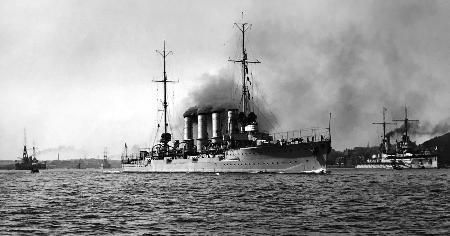
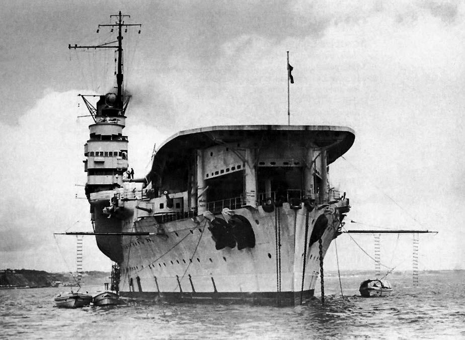
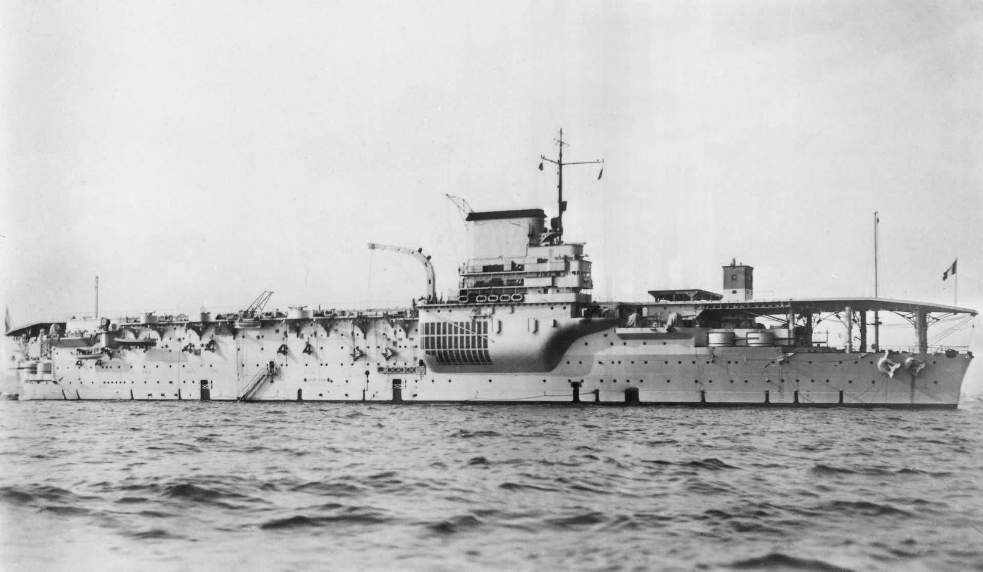
HMS Eagle in 1935. Her conversion from a battleship hullmakesher the closestin conception of the British carriers to Béarn. However, a number ofdifferentchoiceswere made asthe design developed. The bow was faired into the forward end of the flight deck, and the two liftswere widely separated and located at either end ofthe hangar.
The forward liftwas cruciform, enabling aircraft to be struckdown with wingsdeployed immediately on landing. This proved to be a far superior arrangementto thatadopted bythe French.
(CourtesyofDavid Hobbs)
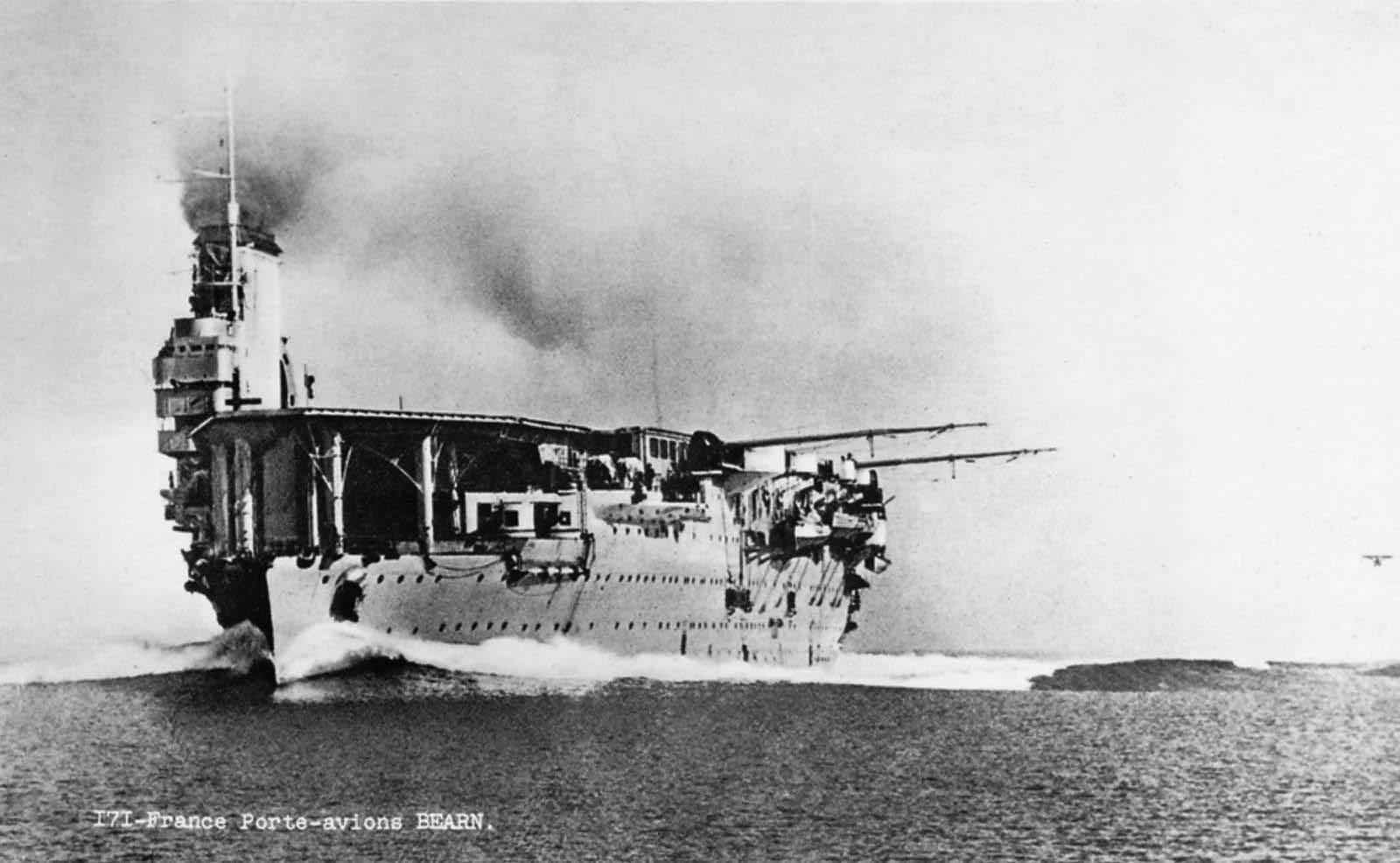
developments. In early 1920 a French commission visited Britain and was given a tour of the first ‘through-deck’ carrier conversion, HMS Argus,to observe aircraft handling and flying operations. According to David Hobbs,1 drawings of Eagle’saviation and island arrangements were also made available. Out of this visit came a proposal for the conversion of one of the incomplete battleships of the Normandie class, and this was duly incorporated in a new building programme designated Project 171. Staff requirements included:
– the embarkation of the maximum number of wheeled aircraft, and the ability to operate seaplanes in harbour –a continuous wooden flight deck at least 150m long, with the maximum possible width and no obstructions –a hangar connected to the flight deck by two lifts, of which the larger should be 20m by 12m –an access bay 20m wide for seaplanes at the after end of the hangar
– speed and endurance comparable to the battleships of the Bretagne class (ie 21 knots, 6000nm at 10 knots) – light vertical armour plating and protection against mines and torpedoes.
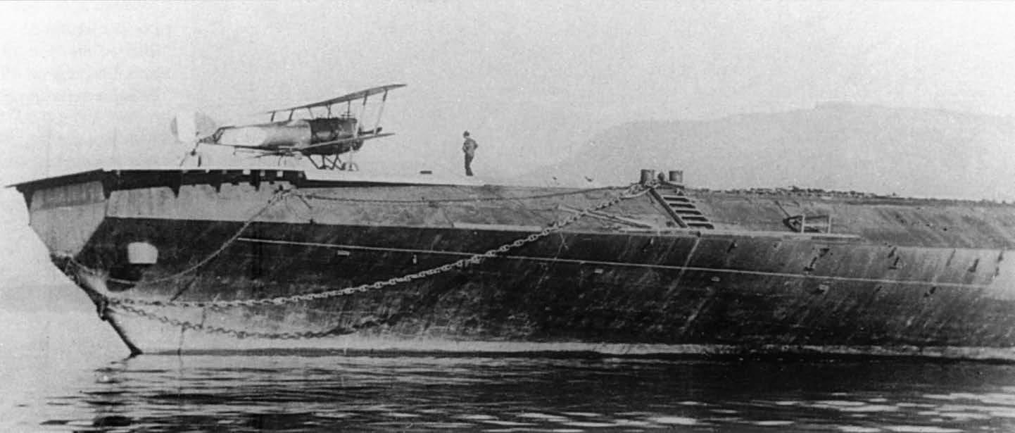
The hull of Béarn, which had been launched without ceremony to clear the slipway on 15 April 1920 and was complete up to the lower armoured deck, was selected for trials. Initial modifications involved a wooden platform 43m by 9m with an access ramp constructed directly on top of the lower armoured deck. The improvised arrester system used for the trials was based on transverse cables raised on circular pieces of cork and weighted with bags of sand. Successful take-offs and landings at Toulon during late October 1920 led to initial studies by the STCN for a full conversion. However, there was still some hesitation about whether it would be better to complete the ship as a battleship or a carrier, and no final decision was made.
The Washington Conference then intervened. Following its conclusion the Marine Nationale decided to proceed with the proposed conversion of Béarn, and this decision was formalised in the 1922 Naval Programme. Béarn was selected rather than one of her sisters because she was the least complete; she would therefore be easier
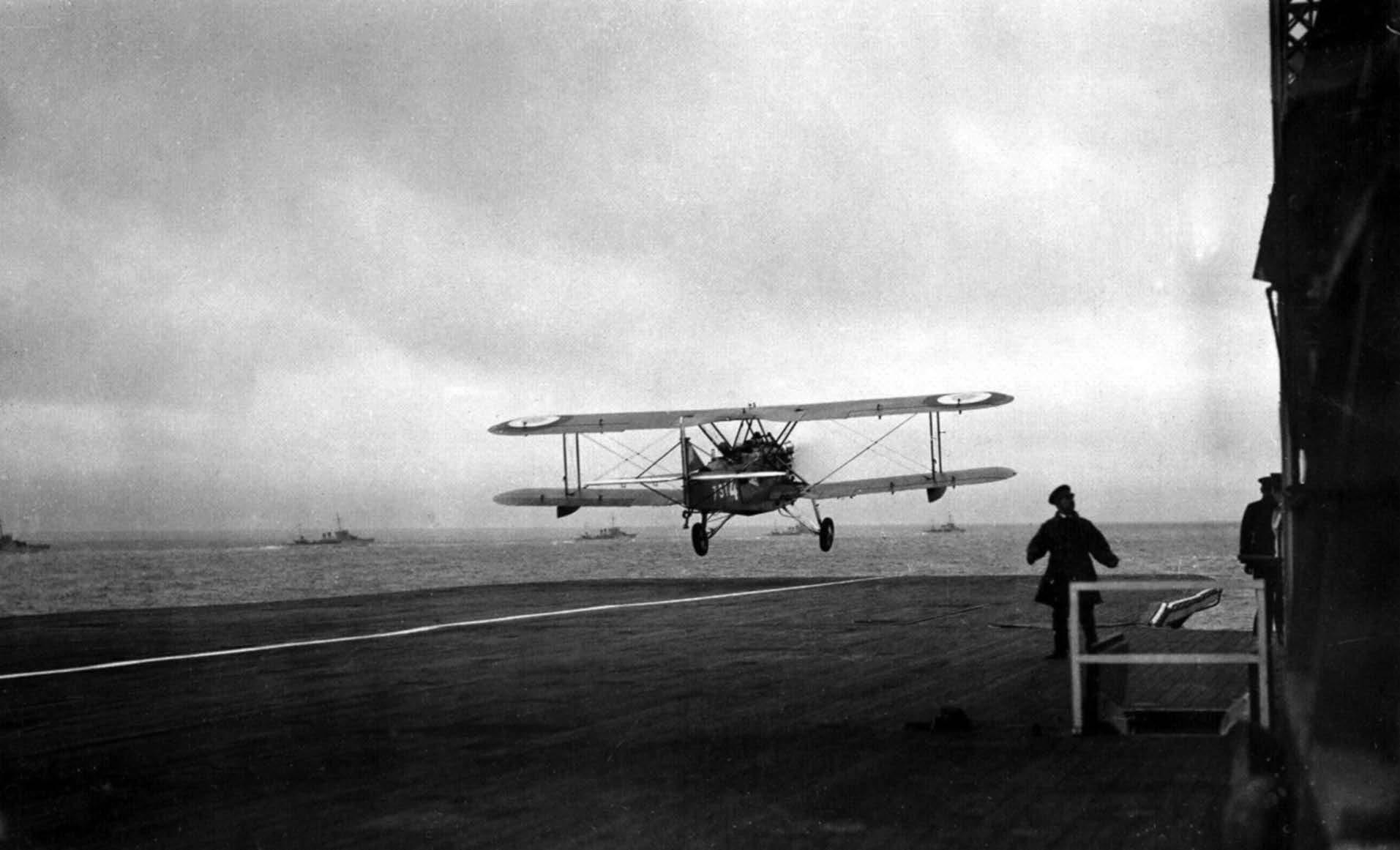
The initialtake-offsand landingsusing the temporary wooden flightdeckwere made byLVPaulTeste in a two-seat Sopwith 11⁄2 strutter in October 1920. During the 1921 trials, the Sopwithswere replaced by the two-seatHanriotHD.3. The aircraftin the photo isbeing prepared for take-off. In order to give the aircraftthe correct attitude the rear ofthe fuselage hasbeen raised on a trestle. (Private collection)
to modify without having to dismantle much of the existing steelwork, while at the same time having access to the machinery and other components already delivered for the other ships. Detailed plans were drawn up –although they would subsequently be subject to numerous modifications – and the contract for completion by the builder, F C Méditerranée at their La Seyne shipyard, was signed on 4 August 1923. The anticipated cost was 66.33 million French francs, of which 190,000FF were for the demolition of existing structures (452 tonnes).
A TacticalFramework
The influence of Britain’s Royal Navy, rightly regarded as being at the forefront of naval aviation, went far beyond the technical and the operational. The Royal Navy of 1918 saw the aircraft carrier as key to providing scouting for the battle fleet in three dimensions, so reconnaissance aircraft were initially to be the key component of the air group. The air space over the battle fleet would also need to be denied to the enemy, hence the need for fighters. These ideas would subsequently be developed: it became clear that aircraft would be equally useful for spotting for the big guns, given ever-increasing ranges of engagement, for torpedo attack, which had the potential to slow an enemy fleet attempting to escape, and for antisubmarine patrol.
The air group initially envisaged for Béarn was to comprise two squadrons each of twelve reconnaissance aircraft plus a single squadron of eight fighters, for a total of 32 aircraft. The second reconnaissance squadron would subsequently be replaced by a squadron of torpedo attack aircraft. This conformed with RN theory and practice.
Royal Navy thinking around 1920 favoured two different types of aircraft carrier: one designed to operate in company with the battle fleet, with an air group comprising fighters, spotters and torpedo attack aircraft, the other intended to operate with the strategic scouting forces in the van, the air group being biased towards fighters and reconnaissance aircraft. Both types would need a small speed margin over the ships they would accompany, so the slower carriers (initially Argus and
Eagle) would operate with the battle fleet, while the converted light battlecruisers, which were capable of top speeds in excess of 30 knots, would operate with the battlecruisers and light cruisers in the van.
The French had no battlecruisers, and the armoured cruisers that had survived the war were little faster than the 20/21-knot dreadnoughts, hence the staff requirement for speed and endurance comparable to the battleships of the Bretagne class. It would, in any case, have proved difficult to increase the top speed of Béarn beyond that of the original Normandie design given that a proportion of the hull volume occupied by machinery in the original plans would have to be reallocated to provide air ordnance magazines, aircraft spares and aviation fuel under armour. Nevertheless, the lack of any speed margin over the battleships showed a lack of appreciation of the need for an aircraft carrier to manoeuvre independently in order to launch and land aircraft into the wind.
Machineryand Lower Hull
When Béarn was launched in 1920 she was complete only to the lower armoured deck. Neither the armour belt nor the propulsion machinery was in place.
As designed the first four ships of the Normandie class were to have a composite propulsion plant, with turbines (for high speed) on the inner shafts and reciprocating engines (for cruising/endurance) on the wing shafts. Béarn, on the other hand, would have had turbines
throughout, to make it easier for her to operate in company with the three ships of the Bretagne class.
Steam for the reciprocating engines and the turbines was to be supplied either by 21 Guyot–du Temple–Normand boilers, or 28 Belleville boilers, both models being rated at 20kg/cm2; the Belleville boiler was of the traditional large watertube type, while the Guyot–du Temple–Normand boiler was a small-tube model derived from the boilers fitted in contemporary destroyers. The boilers were disposed either as seven rows of three or seven rows of four in three boiler rooms. Both types burned coal, for which there was extensive bunkerage outboard of the boiler rooms (see Machinery plan)
The reversion to a composite propulsion plant in the Normandie class was the result of experience with direct drive turbines in the battleships of the Danton class. When the latter ships entered service in 1911 it quickly became apparent that coal consumption at moderate speeds was extraordinarily heavy. Since ships spent most of their active service lives steaming at cruise speed, even in time of war, this was a major concern. There was a cost in endurance, a financial cost, and a heavy price to pay for the crews: coaling was a tedious, dirty and backbreaking task which with high fuel consumption had to be performed with even greater frequency. It was anticipated that the reciprocating engines on the outer shafts would provide a range of 3,375nm at 16 knots and 6,500–6,600nm at 12 knots (almost twice the radius of the Bretagne class).
For Béarn as a carrier it was decided to adopt the
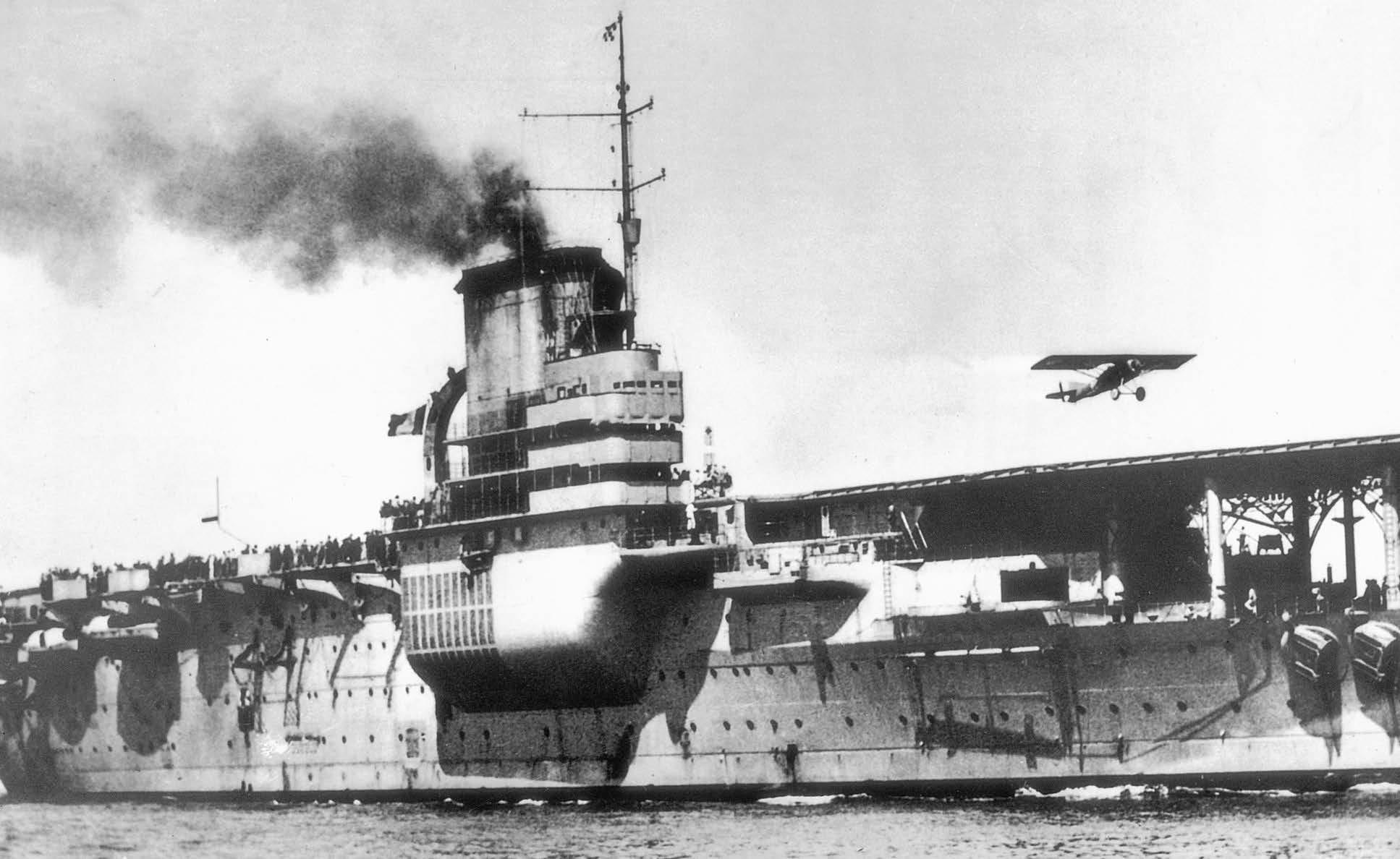
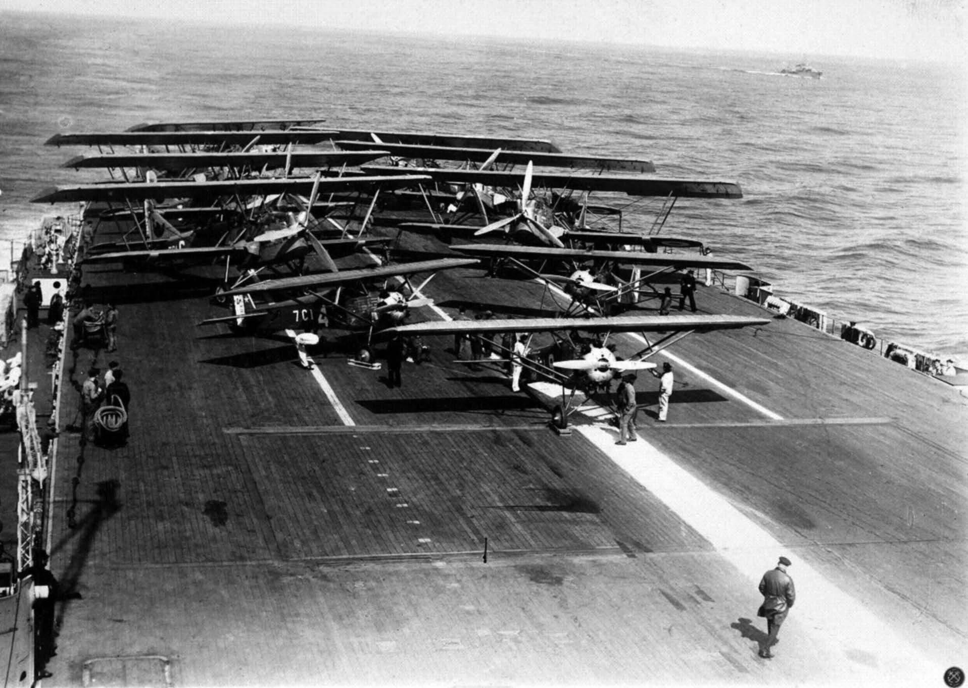
A Gourdou-Leseurre GL.22 single-seattrainer takesofffrom Béarn during landing trialsApril–June 1927. Note thatthe forward 155mm casemate guns have notyetbeen embarked. (Privatecollection, courtesyofPhilippe Caresse)
composite plant planned for her sisters, and to utilise the reciprocating engines and turbines intended for the first ship of the class, Normandie. Each of the VTE engines in the wing compartments, built by A C Loire at their SaintDenis factory, had four cylinders (HP, IP and two LP), and drove a four-bladed propeller with a diameter of 5.2 metres; shaft revolutions were 115rpm. Quite apart from their greater efficiency at low and moderate speeds, the reciprocating engines had the advantage of being able to be reversed to drive the ship when going astern.
The turbines in the inner compartment comprised a single HP turbine (to starboard) feeding into a single LP turbine (to port), both of the Parsons type and likewise built by A C Loire. The turbines were ahead-only, and the adoption of a composite power plant meant that there was no need for separate cruise turbines. The propellers driven by the turbines on the inner shafts were of highresistance bronze; they had three blades and a diameter of 3.44m; shaft revolutions at full speed were 280rpm. The twin balanced rudders were directly abaft the centre shafts; each had a surface area of 20.7m2.
The main condenser for the turbines was located in the centre engine room just forward of (and above) the LP turbine. The condenser rooms for the reciprocating engines were directly abaft the outer engine rooms, and
BuildingData
Builder: F CMéditerranée, La Seyne
Laid down: 5 January1914
Launched: 15 April 1920
Manned for trials: 1 September 1926
Commissioned: 5 December 1927
Entered service: 1May1928
were separated by feed water tanks disposed along the ship’s axis.
By the time the reconstruction of Béarn had been authorised, oil firing had been adopted for all new construction. Oil not only had a higher calorific value than coal, but it could be pumped on board and around the ship, thereby easing the task of the stokers and enabling their numbers to be reduced. It was decided to replace the original boilers with a new type of Normand small water-tube oil-fired boiler Only twelve were needed to supply the necessary steam for the 40,000CV propulsion machinery, and these were accommodated in the forward pair of boiler rooms and disposed in four rows of three (see plans). The fuel oil was stowed not in the original coal bunkers outboard of the boiler rooms,
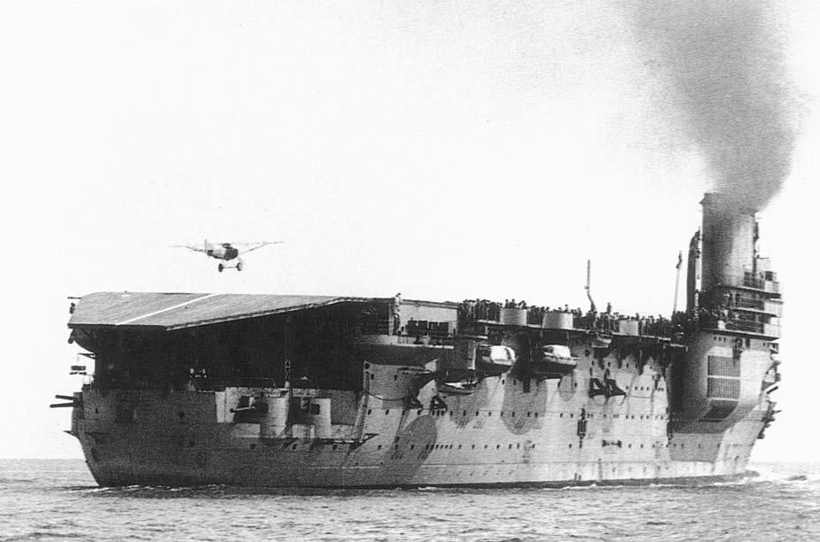
Béarn conducting landing trialswith a Gourdou-Leseurre GL.22 trainer April–June 1927. The after section ofthe flightdeckwas sloped down at10 degreeswhen the ship wasfirstcompleted. (Private collection)
2x37mm AAguns
2x155mm LAguns
2x155mm LAguns 1x75mm HAgun 1x75mm HAgun 2x75mm HAguns 2x75mm HAguns
Note: Adaptedfromplansdated LaSeyne24December1928.
2x37mm AAguns
Thedr aw ingr epr e sents Béar n as sheap pearedin1930,b y whichtimethefor w ar dsectionof theflight dec kha dbeenangleddo wn w ardt o4.5degr ee s andtheangl eoftheaf t ersection ha dbeenreduc edtomat c h. Thewhiteline sp aral l el t othecentr e-line,m ark ingthelandin g ar e a,w ou l dbeext endedo v erthecentrelif t during1931,andin September1932theaf t er mastw ou l dberemo v edandr ep l acedb y aerial s pr ea der s attheaf t erendof thef u nnel .
©JohnJordan2018
HangarDeck
Characteristics(1928)
Displacement: 25,335 tonnesnormal
Dimensions:
Length175.00m pp; 182.50m oa
Beam27.17m wl
Draught8.86m aft
Aviation:
Flightdeck180m x27m
Heightabove waterline 15.65m
Hangar124m x19.5m x6.5/5m
Lifts(LxW)F(fwd): 8m x12m
R (ctr): 10m x15m
T (aft): 15m x15m
Air group9 fighters
9 recce bombers
9 torpedo attack
Machinery:
Boilers12 Normand smallwater-tube, 20kg/cm2
Enginesfour-shaft mixed propulsion: two 4-cylinder VTEengineson wing shafts Parsons HP and LP turbineson centre shafts
Propellers5.20m diameter on wing shafts
3.44m diameter on centre shafts
Horsepower40,000CV
Speed 21.5 knots
Oilfuel2,100 tonnes
Endurance 6,500nm at10 knots
Generatorsfour turbo-generatorseach 400kW
Armament:
LA guns8 x155mm/50 Mle 1922 in casemates
HA guns6 x75mm/50 Mle 1924 in single mountings
LightAA8 x37mm/50 Mle 1925 in single mountings
12 x8mm HotchkissMG Mle 1914
Torpedo tubes4 a/w tubesfor 550mm torpedoes
8 torpedoesMle 1923D
Protection:
Main belt83mm
Decks24mm PBS+ 28/70mm PBI
Casemates50mm
Boats: 1 x10-metre steam pinnace
1 x13-metre motor boat
1 x11-metre motor boat
1 x9-metre motor boat
1 x13-metre pulling pinnace
1 x11-metre pulling pinnace
2 x9-metre pulling cutters
2 x8.5-metre whalers
2 x5-metre dinghies
but in two groups of tanks fore and aft of the two remaining boiler rooms, the coal bunkers being retained for protection (see below). The forward group of tanks occupied the spaces formerly allocated to the forward torpedo flat and the magazines, shell rooms and handing room for the forward quadruple 34cm gun turret; the after grouping replaced the midship 14cm magazine and part of the original after boiler room.
Once the arrangement of the main propulsion machinery had been fixed it was possible to decide how to reallocate the remaining volume in the lower hull. In general terms this involved the suppression of the magazines, shell rooms and handing rooms for the three 34cm quadruple mountings, together with the magazines and handing rooms for the secondary 14cm battery. The original third boiler room was combined with the ammunition stowage and handling spaces beneath the midship turret to create a capacious aviation store that included a magazine for the largest 410kg bombs, and there were further magazines for aircraft ordnance in place of the 34cm magazine and shell room aft. The magazines for the revised armament (see below) were located at the fore and after extremities of the 2nd and 3rd platform decks.
Electrical power for the ship was supplied by steampowered turbo-dynamos each with an output of 400kW feeding a 230V circuit. The four units installed in Béarn were those built for her uncompleted sister Flandre. In the original plans they were to have been mounted in wing compartments outboard of the midship 34cm turret; however, in Béarn they occupied two compartments offset to port and to starboard abaft and forward of the engine rooms respectively, within the protective ‘box’. They would be supplemented by two 150W diesel generators higher up in the ship, located on either side of the main deck, for use when the carrier was alongside.
Protection AgainstEnemyVessels
Main guns
It was recognised that independent manoeuvre could potentially expose an aircraft carrier to the enemy’s
Complement:
Asprivate ship 45 officers, 830 men (includesair group)
advanced scouting forces. The British Argus was an experimental mercantile conversion, and was fitted with neither low-angle guns nor protection. However, the carriers Hermes and Eagle featured not only a battery of low-angle guns comparable to that of a contemporary light cruiser, together with a massive control top to direct low-angle fire, but side and deck armour for the hull capable of withstanding cruiser shell. As originally designed, both ships were to have mounted nine 6in (152mm) guns;2 Hermes was given a 3in (76mm) belt and a 1in (25mm) deck, Eagle a 4.5in (114mm) belt and a 1.5in (38mm) deck.
Béarn was completed with eight 155mm guns in casemates, mounted in pairs at the four corners of the ship. The forward two pairs had a command of 10.06 metres, the after guns 6.84 metres. The end guns were capable of end-on fire and had arcs of 120 degrees; the inner guns could fire within 15 degrees of the ship’s axis and had slightly reduced arcs of 110 degrees (see drawing).
The 155mm Mle 1920 was a 50-calibre weapon developed for the French Navy’s light cruisers of the DuguayTrouin class, the first major new ships to be authorised after the Great War. It fired a an SAP shell weighing 56.5kg with a muzzle velocity of 850m/s using a 19.81kg propellant charge of BM11 in two bags. The projectile, which had a bursting charge of 2.9kg of mélinite (picric acid), had a ballistic cap (for increased range) and two driving bands.
In Béarn each of the guns was mounted within a cylindrical shield with 50mm on the sides3 and a 24mm roof. The mountings allowed a maximum elevation of +40 degrees, giving a theoretical range of 25,000 metres, and the guns could be depressed to -3 degrees. There were separate hoists for projectiles and propellant charges for each pair of guns. These were from Béarn’s uncompleted sister Flandre and were capable of supplying twelve complete rounds per minute; the projectiles were lifted in cases of three, the half-charges in cases of six. There were chutes behind the guns that could hold 18 ready-use projectiles; the corresponding propellant charges were stowed vertically in racks against the rear wall of each casemate. The standard ammunition provision for the LA
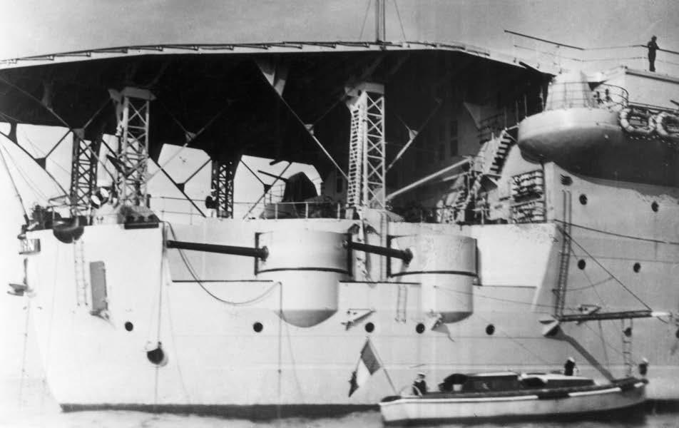
An unusualbow view of Béarn, with the forward 155mm casemate gunsprominent. The aerialspreaderson the after end of the funnelindicate thatthe photo wasprobablytaken in 1933–34. (DR)
guns was 2,000 shells, including 500 tracer for night fire, and 4,200 half-charges, equivalent to 250 combat rounds per gun.
Mounting the 155mm guns in paired casemates at the four corners of the ship meant that they were fore and aft of the hangar, which could therefore occupy the full width of the hull. This meant that hangar volume was significantly greater than in Hermes and Eagle, which had their LA guns mounted in open shields on either side. However, it also precluded the operation of seaplanes from the quarterdeck, as initially envisaged, because of the location and height of command of the after casemate guns.
Torpedoes
The original plans featured no fewer than twelve abovewater tubes for the new 550mm Mle 1923D torpedo, as in the contemporary light cruisers of the Duguay-Trouin class. However, the number of torpedo tubes was progressively reduced from twelve to six and finally, following an amendment to the contract dated 12 August 1925, to four. The tubes, which were on the main deck with a command of 3.8 metres, ran on semi-circular tracks that permitted an angle of train of 30 degrees either side of the beam. When not in use they could be retracted within the hull. Eight torpedoes – two per tube – were stowed, complete with warheads, on racks close to the tubes fixed to the side bulkheads of the aircraft assembly and repair area beneath the hangar (see below).
Fire control
Range data for both the main guns and the torpedoes were supplied by four 3-metre coincidence rangefinders mounted on sponsons to port and starboard of the flight deck amidships and aft. The rangefinder arms were given a 0.5-metre clearance above the flight deck to ensure allround coverage, except where they were masked by the island. The Postes Centraux, divided into a lower steering position on the centre-line and a transmitting station to port, were located at the forward end of the
Close-up ofthe after 155mm casemate gunsto starboard. The cylindricalshieldswere protected by50mm plating. (Musée de la Marine, courtesyofJean Moulin)
Protection Scheme
Normandie Class
Béarn as Aircraft Carrier
Note: Allmeasurements are in millimetres.
2nd platform deck. As originally conceived they were considered too small and cramped, and were extended while the ship was fitting out by adjusting the position of the bulkheads separating them from the forward 155mm magazines. The ship was completed with two Mle 1923B mechanical computers to handle two separate targets, both housed within the fire control position. However, some of the fire control equipment was delivered late and fitted only after completion.
Protection
The Normandie class as designed had the classic protection system associated with the distinguished naval architect Emile Bertin: a high, deep belt, with upper and lower armoured decks and a closely-divided cellular layer between. The main belt, which was of face-hardened steel, would have had a maximum thickness of 300mm, reducing at the ends and tapering below the waterline, and was secured by armour bolts to a teak backing. The upper armoured deck (PBS) comprised two layers of 13mm steel plating, and the lower armoured deck (PBI) two layers of 14mm steel, with reinforcing plates of special steel 42mm thick on the slopes for a total thickness of 70mm. The cellular layer comprised an outer cofferdam subdivided into watertight cells each a single frame in length, with coal bunkers inboard to provide additional protection against shells that succeeded in penetrating the belt or the upper armoured deck. The system was designed to prevent large-calibre shell (305mm/12in and above) from reaching the ship’s vitals.
There would also have been an upper belt of 160mm extending for most of the length of the hull to protect the 14cm casemate battery (see Protection plan). Such a system was not only unnecessary in a ship designed to resist cruiser and destroyer shell, but it was heavy, accounting for some 30% of displacement, and face-hardened armour was costly. When Béarn was taken in hand for conversion, the hull was complete only up to the lower armoured deck. This was retained in its original form, but the thickness of the plates that made up the main deck was reduced from 13mm to 12mm, for a total thickness of 24mm. The main armoured belt was replaced by plates of armour-quality (‘special’) steel with a uniform thickness of 83mm, secured directly to the hull plating as in contemporary cruisers. It comprised three strakes, not two, and extended from the main deck (PBS) to 3.12 metres beneath the waterline. Not only were the original coal bunkers retained, but they were extended aft so as to provide protection not only for the boiler rooms but for the engine rooms (see GA plans). They were packed with coal that remained in place and was not consumed. As in the original Normandie design, there was an inner torpedo bulkhead of 20mm nickel steel (two layers each 10mm thick) lined on the outside by flexible corrugated plating of 10mm mild steel that was designed to act as a spring when exposed to a pressure wave. At its widest point this underwater protection system had a depth of 4.3 metres. However, it was feared that this would not be sufficient to protect against the increasingly large warheads of modern torpedoes, and
©John Jordan 2018
British-style bulges would later be proposed (see below).
The total weight of protection, including the coal, was 5,000 tonnes, which was an impressive figure for an aircraft carrier – the corresponding figure for the battleships of the Bretagne class was 7,070 tonnes, although this did not include the 2,000 tonnes of coal in the side bunkers, which would have been burned in the boilers.
Aviation
Having made a detailed study of British carrier developments during the visit of mid-1920, the French opted for a large two-tier hangar topped by a broad flight deck served by three aircraft lifts, with a narrow island to starboard incorporating a large single funnel. The weight of
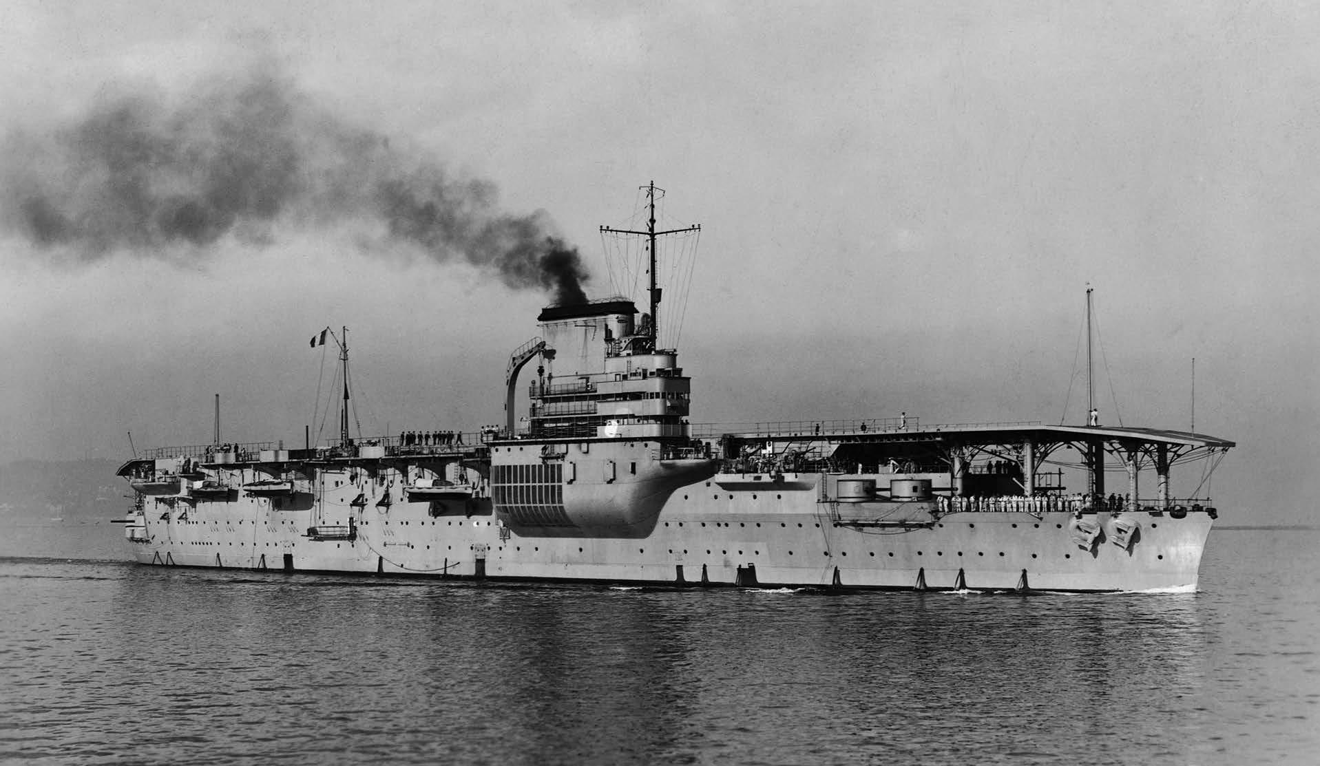
Béarn steaming at high speed during her trialsin late 1927. The hinged W/T maststo port are in the lowered position; the masts were suppressed in 1928 and replaced bya fixed mastto starboard, abaft the island. (DR)
the island had to be compensated by solid ballast comprising 872 tonnes of cemented pig iron in the double bottom to port; this had the additional effect of lowering the centre of gravity and improving stability.
Due to concerns regarding the conning of the ship from the low bridge at the forward end of the island, particularly at night, the design incorporated a retractable charthouse at the forward end of the flight deck, as in the British carriers Argus and Furious. This could be raised to a height of 5.4 metres above the deck using electric motors – a procedure that took two minutes. There was a Poste de navigation on the upper level with a hinged magnetic compass set into the roof, and a sea cabin for the commanding officer directly below; the third level housed the calculating position for the HA guns, the
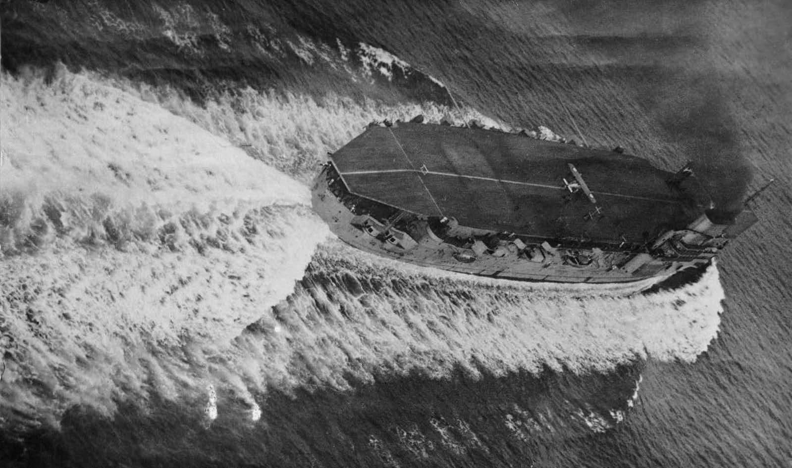
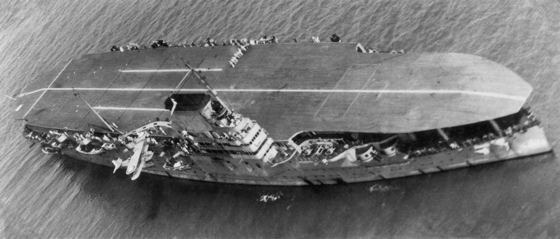
An overhead of view of Béarn on her power trials, steaming at19.7 knots. (DR)
fourth the lift machinery. Only the upper two levels were ever above deck, and when the lift was in the lowered position there were views forward and to the sides beneath the flight deck. As flying operations at night were not envisaged, there were also retractable masts carrying the main navigation lights on (or close to) the centre-line fore and aft.
The concept of an island was the subject of intense debate in all the major navies during this period. The aviation community generally preferred a clear deck free of any obstruction that might limit wingspan, or fixed structures that might create air turbulence. However, this then posed the problem of how to dispose of the large volume of hot funnel gases generated when the ship was steaming at high speed. It also precluded locating the command spaces necessary for conning the ship and supervising flight operations above the flight deck, hence the adoption of a retractable charthouse in the British Argus and Furious, both of which had flush decks. As early as October 1918 a narrow island superstructure of wood and canvas had been built at Rosyth and installed to starboard on Argus Trials showed that the island structure produced little turbulence in itself, and that its presence actually helped pilots to orientate themselves when coming in to land. It was subsequently removed from Argus in order to maximise the width of the flight deck, but the decision was taken to complete Hermes and Eagle with islands to starboard, and plans of the latter shipwere made available to the French commission in early 1920. In appearance the island adopted for Béarn bore a marked visual resemblance to the wood-and-
canvas model fitted experimentally in Argus, with a single large narrow funnel.
The adoption of an island structure did not erase concerns about the potential turbulence over the flight deck caused by the hot funnel gases, and for Béarn the French devised a novel solution. A large streamlined housing (generally referred to in the French Navy as the cul de lampe or ‘lamp base’) was constructed beneath the funnel on the starboard side with rows of large, rectangular air intakes that were connected by ducting to the boiler uptakes. The hot combustion gases were mixed with cold air from outside the ship, thereby reducing the temperature of the gases that emanated from the funnel,4 and were drawn down onto the after part of the flight deck. This seems to have been reasonably effective, as a second bank of intakes was fitted when the ship was reboilered in 1934–35 (see below).
Flightdeck
The flight deck was approximately 15.5 metres above the waterline at normal load and was supported on the walls of the hangar amidships and by pillars above the open forecastle and quarterdeck, which were used primarily for line handling and refuelling. It comprised two layers of 12mm steel plating with overlapping plates, topped by wooden planking of African teak (Iroko) with a thickness that varied between 50mm and 70mm. The flight deck was 180 metres long and had a maximum width of 27 metres. The forward section was horizontal when the ship was first completed in 1927, and the after section was angled down at 10 degrees. Following early manoeu-
A fine studyof Béarn in 1930–31. The flightdeckisnow sloped 4.5 degreesfore and aft. The ‘lamp base’ beneath the funnel, with its rows of rectangular air intakes, isparticularlyprominent. (Privatecollection)
vres in which it became clear that it was difficult for the carrier to maintain her station with the fleet when she had to turn into the wind to land aircraft (see below), in December 1928 the forward end of the flight deck was angled down at 4.5 degrees to permit landings over the bow, and in a short refit at the end of the following year the after end of the flight deck was raised to a similar angle. Aircraft used only the horizontal central section of the flight deck for take-off and landing, so the two breaks in the deck were clearly marked by broad transverse white lines. Galleries ran on either side of the flight deck; they were 1.5 metres wide, increasing to 2 metres where the machine guns were located, and punctuated by broader sponsons for the HA guns and rangefinders.
The flight deck and hangar were served by no fewer than three aircraft lifts, each of which was sized for a specific type of aircraft. This was a significant departure from contemporary British practice, which was characterised by a large ‘T’-shaped or cruciform lift at the forward end of the hangar able to strike down the largest aircraft with wings deployed, and a narrower lift with a rectangular (or cruciform) configuration aft that could raise aircraft from the hangar ready to be spotted for take-off, possibly with wings folded. Operational doctrine in both navies was to strike down an aircraft directly on landing before the next aircraft landed on, a process that generally took five or six minutes, as the landing interval was dictated by the speed of operation of the lifts; neither navy operated a deck park. For similar reasons the maximum strike that could be spotted for
take-off, leaving sufficient length of deck available, was six aircraft, and the Royal Navy ‘flight’ – the standard unit of organisation – was sized accordingly. French naval air squadrons were generally embarked as two or three sections each of three aircraft, so take-off and landing operations were generally by two sections.
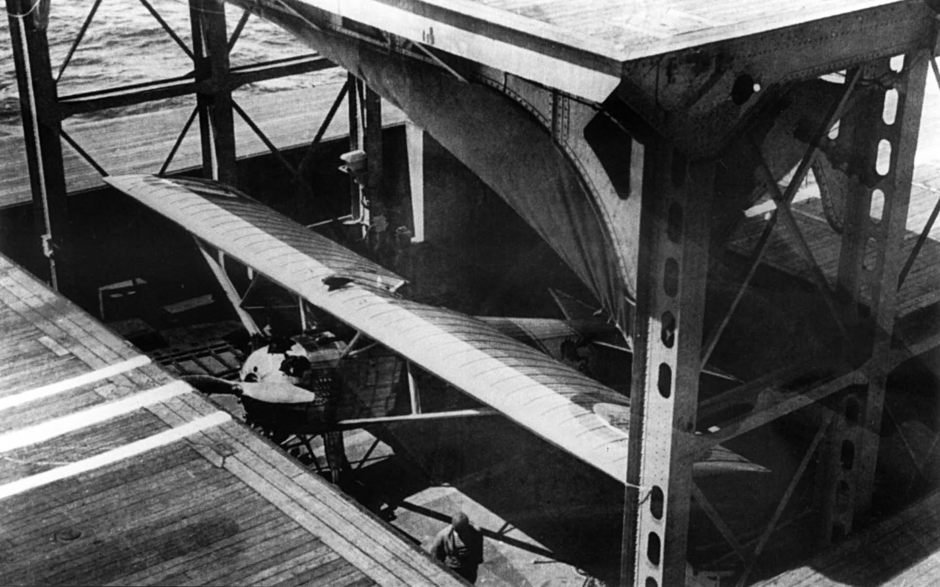
The forward lift on Béarn, which was 8 metres long and 12 metres wide, was sized for fighters, and had a 2-tonne capacity; on the 1928 plans of the ship it is labelled ‘Ascenseur des A.C.’ (A.C. = avions chasseurs). Unusually, it was a two-tier lift with the platforms separated by the height of the hangar. In the lowered position the lower platform was at the level of the hangar deck and the upper platform at the level of the flight deck. When the lift was raised to bring up aircraft from the hangar the upper platform was 7.5 metres above the flight deck.5 A 1931 proposal to extend this lift on its after side by adding a rectangular section 1.5 metres long and 5 metres wide was not proceeded with.
The centre lift was 10 metres long and 15 metres wide, and could therefore accommodate the largest scout bombers of the day (A.R. = avions de reconnaissance) with wings deployed. It was complemented by an even larger after lift 15 metres square for torpedo bombers (A.T. = avions torpilleurs); both these lifts had a capacity of 5 tonnes. Because these two lifts occupied the centre of the flight deck and wererelatively slow in operation –three minutes per complete cycle for the centre lift, a full five minutes for the after lift – the open lift shafts were closed by heavy clamshell doors when the lift was at
Béarn in 1932–34, following the removalofthe W/T mastabaftthe island, replaced byaerialspreaderssecured to the after end ofthe funnel. The retractable charthouse isin the raised position, and the two-tier aircraftliftimmediatelyabaftitispartiallyraised. (Musée de la Marine, courtesyofJean Moulin)
hangar deck level to enable flying operations to continue. Despite the technical ingenuity of this solution, it was costly in terms of topweight and the power required to operate the doors, which required their own electric motors. It was also more vulnerable to breakdown and action damage – although three lifts did offer greater redundancy than two.
All three aircraft lifts and the retractable charthouse were operated by electric motors; large counterweights running in vertical shafts on either side of each lift meant that the power needed to raise the lift was reduced to a minimum. The lifts were designed to operate with a permanent list of 10 degrees, and with a 10-second roll of five degrees. The after lift and the charthouse were specified for six manoeuvres per hour indefinitely, the other two lifts for seventeen consecutive manoeuvres with a 24-hour break, or fourteen consecutive manoeuvres followed by six per hour
Originally there was to have been a palisade similar to those fitted in the early British carriers to prevent the light wood-and-canvas aircraft of the day from being blown over the side on landing. However, this was suppressed by a directive dated 22 April 1925. Instead the French experimented with increasingly sophisticated arrester systems, which by the early 1930s were fully developed.
The first experiments were with five transverse cables strung across the flight deck at intervals of approxi-
mately 16 metres, the first of which was 31 metres forward of the ‘round-down’ across the after lift. The cables were raised 10cm above the deck by circular pieces of cork and weighted down by multiple bags of sand. These were replaced during the first refit of 1928–29 by prototype arrester systems developed by Schneider and Saint-Chamond. The Fieux system manufactured by Schneider worked by friction using restraining drums; the competing Saint-Chamond system used hydraulics. Three cables (two Schneider-Fieux aft, one Saint-Chamond forward) were sited between the after two main aircraft lifts, again at 16-metre intervals (see Profile & Plan). At the same time white stripes were painted 6.5m on either side of the centre-line between the two lifts to mark out the area in which the arrester wires were located; they were later extended forward over the centre lift. The Schneider-Fieux system proved superior, and in a refit late 1932 the Saint-Chamond arrester cable was replaced by a third Schneider model. The pilots who proposed that the forward end of the flight deck be inclined downward also wanted three additional arrester wires between the forward and centre lifts be installed at frames 90, 105 and 120 to permit landings over the bow; however, this measure was not implemented, probably on grounds of cost.6
The landing procedure initially adopted was one pioneered by the distinguished French naval aviator Paul Teste. This involved a horizontal approach between
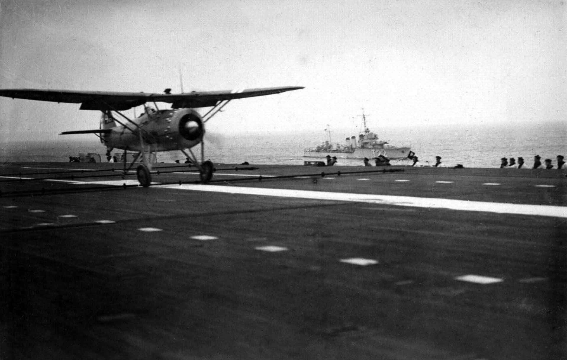
A high-wing monoplane fighter ofthe Dewoitine D.373/376 seriesisaboutto catch one ofthe Schneider-Fieuxarrester wires. The tactical number ‘T22’ painted on the hullofthe destroyer on plane guard dutytellsusthatthe photo wastaken in mid-1939 and that the ship is Frondeur. (Privatecollection)
50cm and one metre above the flight deck. The pilot used a pylon-mounted sighting arm plus the horizon – or sighting arms fore and aft in conditions of poor visibility – to line up his approach. This required considerable skill and nerve on the part of pilot, particularly when the aircraft passed directly through turbulence abaft the flight deck. A later landing procedure developed by JeanJulien-Pierre Lartigue, formerly a naval pilot and captain of Béarn from 1934, involved an angle of descent of 5–6 degrees, even 10–15 degrees. A single sight comprising a red and white hoop 75cm in diameter, mounted atop a manually-operated hinged mast on the centre-line, had to be aligned with a white rectangle 6m by 2m painted on the flight deck 50 metres farther forward, where the wheels were due to touch down. The angle of approach
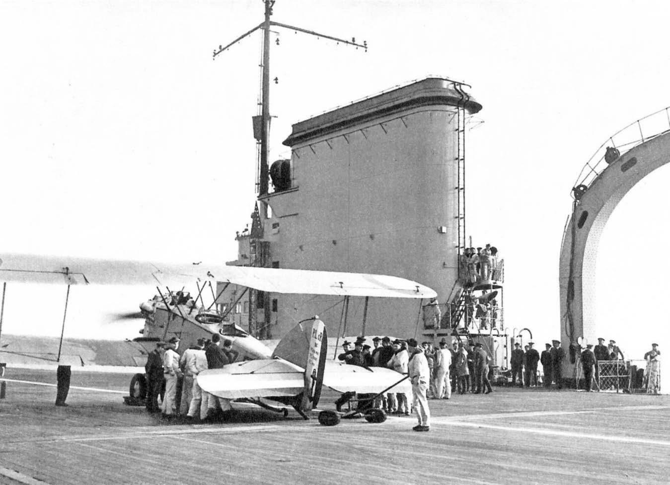
A Levasseur PL.4 reconnaissance aircrafton the flightdeckof Béarn during the late 1920s. The large 12-tonne crane, which was capable oflifting seaplaneson board, can be seen on the right ofthe picture. (DR)
ensured that the pilot came in above the turbulence and could better assess the pitching of the flight deck. The new procedure, adopted from 1935, reduced landing intervals from six minutes to two/three minutes, although the slow speed of operation of the lifts meant that there was little overall benefit.
Finally, abaft the island, was a large goose-neck crane. Its 12-tonne capacity enabled it to be used not only for embarking and disembarking aircraft when Béarn was alongside or from lighters when moored in an anchorage, but to lower and raise seaplanes used for long-range reconnaissance when the ship was in harbour During the early part of her career, Béarn generally operated two CAMS 37A seaplanes in addition to her complement of wheeled aircraft.
An aerialview of Béarn probablydating from 1930–31, prior to the removalofthe W/T mastabaftthe island. A Levasseur PL.4 reconnaissance aircraftissuspended from the crane. (Musée de laMarine, courtesyofJean Moulin)
Hangar
Although the French opted for a two-tier hangar on the B ritish model, as in the contemporary F urious , Courageous and Glorious, only the upper hangar, originally referred to as the entrepont aviation, was employed for operational aircraft. The lower hangar was divided
Centre Lift
From Fwd
Note: Adapted from plans dated La Seyne 24 December 1928.
The officialplansconfirm that, contraryto whathasbeen generallystated in secondarysources, the three aircraftlifts served onlythe upper hangar. When depicted atthislevelthe lift platform islabelled ‘plateforme de l’ascenseurau pointbas’ (platform in itslowestposition). Also, the run ofcable for the counterweightis7.52 metres, the distance between the hangar deckand the flightdeck. The ‘feet’ atthe cornersofthe lift, and the raised hatched for the embarkation ofaviation stores, would in anycase have prevented the liftfrom being lowered to the main deck.
into two spaces: a repair and assembly workshop aft, and a space for the stowage and assembly of reserve aircraft forward.
The upper hangar extended from frame 16 to frame 140, with the smaller lift for fighters at its forward end. It was divided into two for the purpose of aircraft stowage, and into four for damage control. The forward section, from F90 (centre lift) to F132, had a gallery deck above to accommodate the air crews. Hangar height was thereby reduced to 5 metres, which meant that it could accommodate fighters and reconnaissance aircraft only; usable length was approximately 42 metres. The after section, from F16 to F80 (centre lift) had 6.5 metres clearance and could therefore accommodate the larger torpedo bombers. Taking into account the after lift, this gave a usable length of 49 metres. The upper hangar had a nominal width of 19.5 metres, but this was reduced to 15 metres – the same width as the centre and after lifts –once the funnel trunking and ventilation, the winches for boat handling and the ready-use racks for air ordnance were taken into account (see Hangar Deck plan).
There were three asbestos fire curtains: one just forward of the after lift, one just abaft the centre lift, and one between the forward and centre lifts. These divided the hangar into four roughly equal sections and (in theory) prevented fire spreading through the hangar.
Aircraft of the day were generally armed and fuelled on the hangar deck, then raised to the flight deck for takeoff. There was substantial ready-use stowage for air ordnance to the sides of the upper hangar, between the two after lifts (which handled the reconnaissance and the torpedo attack aircraft) and to starboard of the after lift. There were racks for six large 410kg bombs, six 226kg and six 152kg medium bombs, and six 76kg light bombs to port and to starboard, and for ten 400mm torpedoes to starboard of the lift.
The upper hangar was served by three parallel overhead rails in the form of an I-beam 152mm high and 127mm wide, secured to the underside of the flight deck or the gallery deck; these could accommodate cranes or block and tackle used to move aircraft parts (or even whole aircraft) within the hangar. The rails were broken at the lift shafts and/or the fire curtains. The outer pair of rails was extended aft above the quarterdeck to enable aero engines to be transferred from the hangar to one or other of the test beds above the open stern. The test bed to starboard was for in-line or ‘V’-form water-cooled engines; the one to port was for radial air-cooled engines.
The lower hangar was shorter and had compartments to the sides, some of which were employed for accommodation. It extended from Frame 32 to Frame 140, and like the upper hangar had a usable width of approximately 15 metres. The aviation workshop occupied the after end; the remainder of the hangar was an assembly and stowage area for spare aircraft. The hangar was again divided into four by asbestos fire curtains, the location of which mirrored arrangements in the upper hangar. There were large rectangular hatches on the centre-line at the base of each of the three lift shafts for
©John Jordan 2018
the embarkation of aviation stores and ordnance, and smaller hatches for the embarkation of lube oil and aviation fuel offset to port and to starboard, directly above their respective stowage compartments (see below).
Like the upper hangar, the lower hangar was equipped with three parallel overhead rails, secured to the underside of the deckhead. Despite claims in French (and English-language) secondarysources that the three aircraft lifts served both hangars, the plans of Béarn show clearly thatthis was not the case, and that in the lowered position the lifts were at the level of the (upper) hangar deck. A close study of the plans reveals that each of the lifts was fitted with a centre-line rail on its underside that lined up with the axial rails above each of the hangar decks. If an aircraft needed to be transferred between the assembly and repair areas in the lower hangar and the upper hangar, it was suspended from the underside of the lift and raised or lowered accordingly, then moved to the desired location using the overhead rails. This would have been an extremely laborious operation, and makes it clear why the French regarded the upper hangar as the only one capable of actively supporting air operations.
Avgasand oilstowage
Aviation fuel, lubrication oil and petrol for the ship’s boats was stored in individual tanks on the 1st platform deck. There were three groups of avgas and petrol tanks: the first two were located in the forward part of the ship
and offset to port; the third was close to the stern, directly above the steering gear compartment (see GA plans). Total capacity for the air group was 100,000 litres.7 These tanks of volatile fuel were all within the armoured citadel, being protected above by the 24mm plating of the main deck, and to the sides by the 83mm belt of nickel steel. Each of the three groups was surrounded by a protective box filled with inert nitrogen gas.
On the same deck level there were multiple tanks holding 15,000 litres of engine oil for the aero engines (aft of amidships, to starboard) and 39,000 litres for the diesel generators (amidships, on either side of the hatch for aviation stores).
The bomb magazines were amidships and aft and were grouped with the aviation store compartments for ease of access. The bomb magazine amidships could accommodate sixty of the large 410kg bombs, while the after magazine complex had stowage for 68 226kg bombs, 132 152kg bombs and 100 76kg bombs (see Machinery plan). The total weight of air ordnance specified was 62 tonnes.
Air Group
A considerable amount of planning and preparation went into the formation of Béarn’s first air group under Paul Teste and his successors. Each of the three squadrons was to have a nominal strength of twelve aircraft organised as four 3-plane sections. In 1928 Béarn generally deployed with six operational aircraft from each of the three
A Wibault74 of7C1 squadron isbroughtup to the flightdeckbythe forward aircraftliftin 1933. The forward liftwasunusualin having two platforms, and when raised protruded above the flightdeck. (Private collection)
Béarn Air Group
FighterSquadron
Dewoitine D1
–High-wing monoplane; metallicconstruction; 40 ordered for Navy.
–7.5m Lx11.5m Wx2.75m H; 820/1250kg (empty/loaded).
–In service 1925–32.
Wibault74
–High-wing monoplane; metallicconstruction; navalised version ofAir Force W.72; 24 ordered for Navy.
–7.6m Lx10.95m Wx2.96m H; 1060/1550kg (empty/loaded).
–Prototype 1929; in service 1932–38.
Dewoitine 373/376
–High-wing monoplane; metallicconstruction; navalised version ofAir Force D.371; 20 ordered for Navy.
–7.44m Lx11.22m Wx3.42m H; 1295/1860kg (empty/loaded).
–Prototype 1936; in service from 1938; D.376 folding-wing version.
Recce Squadron
Levasseur PL.4
–Single-engine 3-seatbiplane with folding wings; seaplanetype hullwith floatson wings; recce, observation, bombing; four hard pointsfor bombs; 34 ordered for Navy.
–9.67m Lx14.60m Wx3.85m H; 1690/2640kg (empty/loaded)
–In service 1927–30.
Levasseur PL.10
–Configuration and missionsasPL.4 above; 18 ordered for Navy.
–9.75m Lx14.20m Wx3.75m H; 1815/2880kg (empty/loaded).
squadrons; in 1933 this figure was increased to nine, for a total air group of 27.
By the time Béarn entered service in May 1928 the fighter squadron was designated 7C1 (C = chasseur). The first aircraft to serve with the squadron was the Dewoitine D1, a small high-wing monoplane of metallic construction with a wingspan of 11.5 metres and a height of 2.75 metres. The D1 proved to be robust; it was superseded in 1932 by the Wibault 74, which had a similar size and configuration and was well-liked by the pilots who flew it. The Wibault 74 was to have been replaced by the Dewoitine 373: a prototype was trialled in 1936, but a series of accidents resulted in the aircraft being returned to the factory for rebuilding, and it did not enter service until 1938. A folding-wing variant, the 376, was then introduced and replaced the 373 in first-line service; a second fighter squadron was formed with the older model shortly before the Second World War – the squadrons were now designated AC1 and AC2 respectively.
The reconnaissance squadron embarked in May 1928 was 7S2 (S = surveillance). It was formed initially with the Levasseur PL.4, a single-engine, 3-seat biplane with folding wings and a boat-shaped hull. The PL.4 had a wingspan of 14.6 metres, a height of 3.9 metres and a maximum weight of 2,640kg, and was fitted with four
–In service end 1931–33.
Levasseur PL.101
–Modified PL10; 30 ordered for Navy.
–CharacteristicsasPL.10, butslightlyheavier.
–In service 1933–39.
Loire-Nieuport401
–FirstFrench dive-bomber; single-engine gull-wing monoplane; single 225kg bomb; 7 prototypes, then 20 production ordered for Navy.
–9.75m Lx14m Wx3.5m H; 2135/2820kg (empty/loaded).
–In service from Oct1939.
Bombing Squadron
Levasseur PL.7
–Firstaircraftdesigned to launch torpedoes; single-engine 3-seatsesquiplane with boat-shaped fuselage and folding wings; Mle 26DA 400mm torpedo (670kg) or variable bombload using four hard points; 15 pre-series, 30 production modelsordered for Navy.
–11.68m Lx16.50m Wx4.86m H; 2800/3950kg (empty/loaded).
– In service 1930 butreturned to factoryfollowing accidents 1931; then served until1939.
Vought156F
–Exportversion ofSB2U Vindicator; single-engine 2-seat monoplane dive-bomber with variable-pitch propeller & folding wings; three bomb attachmentpoints(one beneath fuselage, one beneath each wing); 40 ordered for Navy; 50 more ordered May1940.
–10.33m Lx12.80m Wx4.32m H; 2138/3300kg (empty/loaded).
–In service from September 1939.
bomb-racks. It was superseded in 1931 by the Levasseur PL.10, which was similar in size, then by the PL.101, a modified PL.10 that served until 1939, when it was due to be replaced by the Loire-Nieuport 401, a singleengine gull-wing dive-bomber that could carry a single 226kg bomb. The latter, however, proved to be underpowered and was never deployed operationally on Béarn. The reconnaissance squadron was rechristened AB2 (B = bombardier) in 1938
The attack squadron was initially designated 7B1, and was initially formed with the same PL.4 aircraft that served with the reconnaissance squadron. In 1930 the PL.4 was replaced by the Levasseur PL.7, a large singleengine 3-seat biplane which was the first French aircraft capable of launching a torpedo. It had a wingspan of 16.5 metres (the upper wing had twice the surface area of the lower), a height of 4.86m, and an all-up weight of 3,950kg. The PL.7 could carry either a Mle 26DA 400mm torpedo weighing 670kg, or a variable bombload using the four hard points beneath the wings. A serious accident in 1931 that involved the aircraft breaking up in mid-air resulted in the PL.7s being returned to the factory for modification. The aircraft then served until 1939, when it was to have been replaced by the Vought 156F, an export version of the US
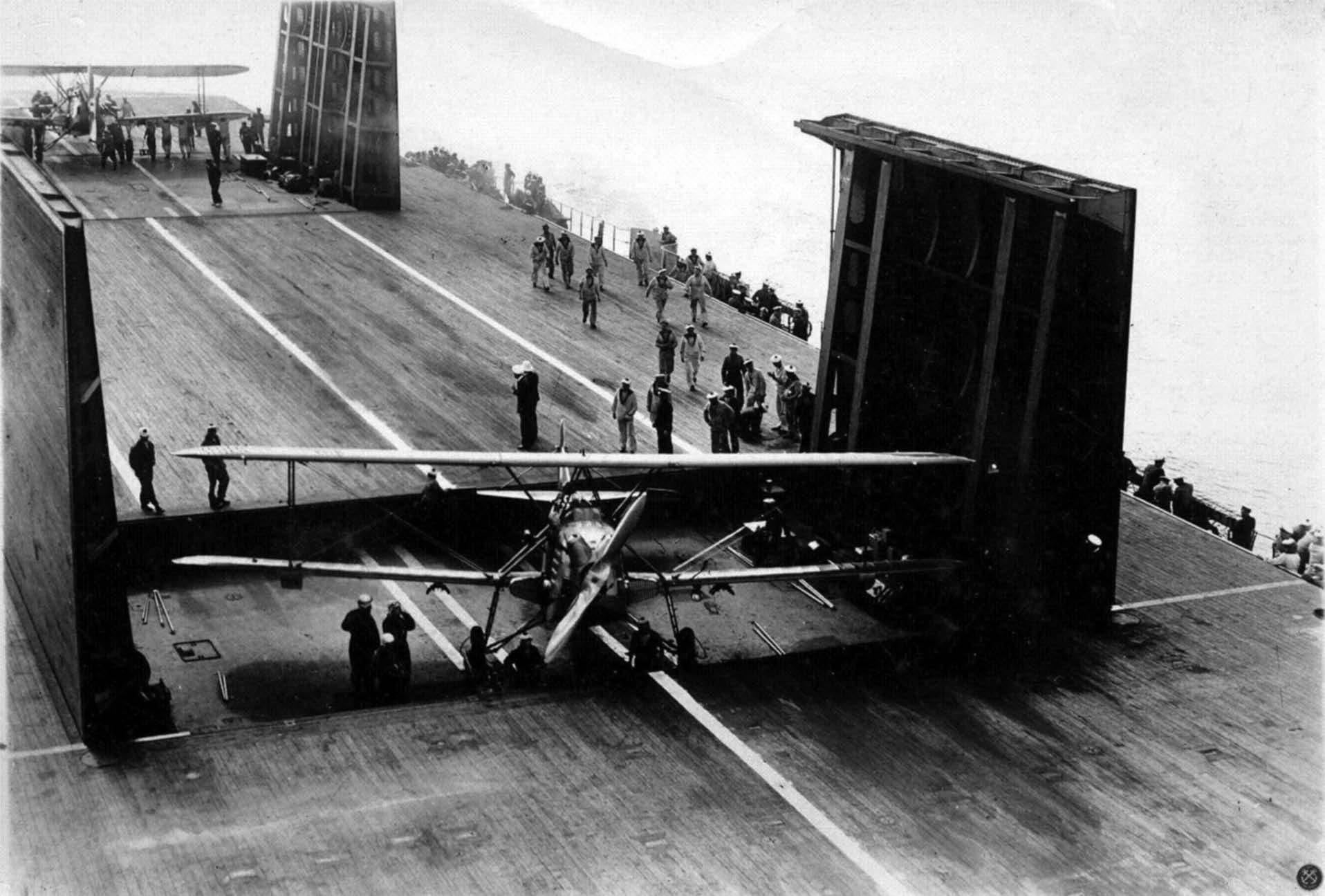
TwoLevasseur PL.101 reconnaissance aircraftof7S1 squadron are broughtup to the flightdeckduring the late 1930susing the centre and after lifts. Note the heavyclamshelldoorswhich ensured the flightdeckremained in operation when the liftswere lowered to hangar level. (Privatecollection, courtesy ofPhilippe Caresse)
Navy’s SB2U Vindicator. The first of these were delivered in August 1939 and entered service the following month, but again the aircraft was never operational with Béarn. The attack squadron was rechristened AB1 in 1938.
Key data for the all the aircraft described above can be found in the accompanying table.
Anti-aircraftGuns
The anti-aircraft armament of Béarn was broadly comparable to that fitted in the contemporary ‘treaty’ cruisers of the Duquesne class.
There were four 75mm/50 Mle 1924 guns on sponsons port and starboard at the forward end of the flight deck, and two further mountings aft. They fired a 5.93kg HE time-fused shell designated OEA Mle 1925 or starshell Mle 1923. Provision was 450 fixed rounds per gun, and close to each mounting there was ready-use stowage for 36 rounds in cases of three. Shields were fitted during the 1934–35 reconstruction (see below). Fire control was provided by two of the new HA directors, each of which was fitted with a 3-metre stereo rangefinder from OPL: one in the gallery to port and a second atop the forward end of the island. Due to delays in development and manufacture these were not in place until 1929. They were modified during the 1934–35 reconstruction, when
the port-side director was relocated to starboard, beneath the crane.
The light AA initially comprised eight of the new semiautomatic 37mm/50 Mle 1925 guns and twelve 8mm Hotchkiss Mle 1914 machine guns. The 37mm guns, which were in pairs fore and aft, used the same ammunition hoists as the 75mm HA guns. The forward magazine held 352 cases, each containing six fixed rounds, and the after magazine 147, for a total provision of 3.000 rounds (375rpg). There was stowage for 90 ready-use rounds close to each of the mountings.
The 8mm Hotchkiss MG, mounted as four sections of three in the gallery amidships to port and to starboard, proved to be ineffectual against modern aircraft; during the reconstruction of 1934–35 they would be replaced by the new Hotchkiss 13.2mm Mle 1929 gun (see below).
Reconstruction 1934–35
As soon as Béarn entered service with the fleet, it became apparent that her comparatively low speed would be an issue. During initial manoeuvres with the battle fleet on 20 July 1928, she altered course to head into the wind while conducting landing operations. After landing two aircraft it took her one and a quarter hours to resume her station steaming at 16 knots, even though the battleships
A view ofthe flightdeckin 1937, with aircraftbeing ranged for take off. The three aircraftnearestthe camera are Wibault74 fightersof 7C1 squadron; behind them are ranged the sixLevasseur PL.7 torpedo bombersof7B1. Atthe after end ofthe flightdeckisa PL.101 reconnaissance biplane – probablythe one assigned to the air group commander. (Privatecollection)
were cruising at only 12 knots. This led to the request from the pilots for the modifications to enable them to land over the bow outlined above.
In January 1931, less than three years after her entry into service, the ship was immobilised due to jamming of the clamshell doors of the centre lift and the poor state of her boilers, and in October the STCN was instructed to undertake a study for a major reconstruction to include:
–replacement of the boilers –modifications to the forward lift –replacement of the 75mm guns by the new 100mm CA being fitted in the aviation transport Commandant Teste.
Further studies were requested to determine the feasibility and cost of:
–replacement of the original propulsion machinery by geared turbines –the fitting of anti-torpedo bulges –enhanced protection of the decks to protect the ship against the increasing threat from land-based bombers.
Estimates were for immobilisation between twelve
months and three/four years, depending on the extent of the works; the cost would be between 33 million and 125 million francs (possibly rising to 200m FF). It was estimated that geared turbines would supply 60,000CV – an increase of 50 per cent – for a top speed of 23.4 knots. However, if bulges were fitted maximum speed would be reduced by more than one knot (22.3 knots). 8 Displacement would rise by about 500 tonnes.
The project was abandoned in part due to the age of the hull – 20 years from laying down by January 1934. Maximum speed would still have been only 22–23 knots – the new fast battleship Dunkerque had a designed speed of 29 knots – and it would not be possible to upgrade protection against aerial bombing. In the event the Minister approved only a limited reconstruction costing 25 million francs, of which 17m FF was for reboilering. This took place at La Seyne and Toulon between Febr uary 1934 and November 1935 and included the following work:
– replacement of the original boilers by six of the new standard Navy-type du Temple small-tube boilers (three per boiler room) –a second bank of vents in the cul de lampe that increased air volume by 50%
–removal of the retractable charthouse and the 550mm torpedo tubes –replacement of the 8mm machine guns by six twin 13.2mm Hotchkiss Mle 1929 AA, mounted to port and to starboard on either side of the after aircraft lift – modifications to the HA directors, and new-model rangefinders for the main and the light AA guns in the gallery to port and to starboard.
During her post-refit trials, on 26 Aug 1935 Béarn attained an average speed of 20.8 knots on the course off the Hyères islands (east of Toulon) – 20.38 knots in the face of a strong Mistral, 21.25 knots in the opposite direction– with five boilers lit.
Following her reconstruction she was redeployed to Brest, arriving in early October 1936. Too slow to operate with the modern cruisers based at Toulon, she was to provide aerial reconnaissance for the elderly battleships of the 2nd Battle Division (Bretagne class). However, when the latter returned to the Mediterranean in the spring of 1939 Béarn remained at Brest. Following the outbreak of war her air group was disembarked, and she was subsequently relegated to the training role, conducting landing qualification trials off the south of France with the latest Vought 156F dive-bomber due to enter service with the Navy. During May and June 1940 she was employed to transport gold to the USA and to bring back the aircraft purchased with it. When the Armistice was concluded on 25 June she was immobilised at Fort-de-France in the French Antilles.
Sources:
Moulin, Jean, Morareau, Lucien & Picard, Claude, Le Béarn et le Commandant Teste, Marines édition (Bourg-en-Bresse, 1997).
Official plans dated La Seyne 24 December 1928, held by the Centre d’Archives de l’Armement, Châtellerault.
Endnotes:
1 British Aircraft Carriers, Seaforth Publishing (Barnsley 2013), 66.
2 The 6in guns for Hermes were subsequently replaced by 5.5in (140mm) guns from the discarded cruiser Birkenhead, and the three quarterdeck mountings were suppressed to enable the ship to operate seaplanes.
3 The figure of 70mm given by Campbell in Naval Weapons of World War Two probably includes a double layer of 10mm steel to which the special steel plating would have been secured.
4 Similar measures were adopted by some navies during the late 20th century to prevent SSMs with infra-red guidance from locking on to the hot funnel gases.
5 The after lift in the IJN carriers Akagi and Kaga was similar.
6 Forward arresting gear was fitted in all US carriers during the 1930s.
7 By way of comparison, the French carrier Clemenceau, completed in 1961, could stow 1.6 million litres of aviation fuel.
8 The bulges would have had a depth of 2.70 metres on either side of the lower hull. They would have increased beam to 32.4 metres – the maximum that could be accommodated in the available dry docks.
ALevasseur PL.101 takesoffduring the late 1930s; the PL.101 could be distinguished from the PL.10 bythe absence ofan axletree as partofthe undercarriage. Béarn isbeing escorted bydestroyersofthe Bourrasque and L’Adroit classes. (Private collection)