Introduc�on to Show Networking
JOHN HUNTINGTON
ZIRCON DESIGNS PRESS
Copyright © 2020 by John Huntington, All Rights Reserved
No part of this book may be reprinted or reproduced or utilized in any form or by any electronic, mechanical, or other means, now known or hereafter invented, including photocopying and recording, or in any information storage or retrieval system, without permission in writing from the publisher.
Although every precaution has been taken to verify the accuracy of the information contained herein, the author and publisher assume no responsibility for any errors or omissions No liability is assumed for damages that may result from the use of information contained within.
Trademark notice: Product or corporate names may be trademarks or registered trademarks, and are used only for identi�cation and explanation without intent to infringe.
Zircon Designs Press Brooklyn, NY, USA www.zircondesigns.com
Print ISBN-13: 978-1-7357638-0-4
EBook ISBN-13: 978-1-7357638-1-1
LCCN: 2020918289
BISAC: Performing Arts / �eater / Stagecraft
Version 1 0, October 5, 2020
PREFACE
What’s Included and Not Included? xiv
For Whom Is �is Book
Written? xv
How Should �is Book Be Used? xv
Conventions xvi
Disclaimers xvi
�anks to My Production Team xvi
Website and Lecture Videos xvi
CHAPTER 1
INTRODUCTION
What Is a Network? 1
How are Networks Used on Shows? 1
Lighting Networks 1
Sound Networks 3
Video Networks 3
Scenery Networks 4
Networks for Pyro, Costumes, Props, Show Control, You Name It! 5
Network Types 5
Local Area Network (LAN) 6
Wide Area Network (WAN) 6
Internet 6
Networking Concepts 6
Bit Rate/Bandwidth 6
Determinism 7
Data Encoding 7
Error Detection 8
Packets and Frames 8
Packet Forwarding 8
Networking Using Electricity 10
TIA Category Cables 10
Shielded or Unshielded Cables 11
Solid or Stranded Conductors 11
RJ45 (8P8C) Connectors 11
TIA-568 Cabling Standard 12
Networking Using Light 14
Fiber Types 14
Connectors 15
Networking Using Radio 15
Layering 15
Open Systems Interconnect (OSI) Model 17
Here’s Everything You Need To Know About Show Networking! 19
CHAPTER 2
ETHERNET
Logical Link Control (LLC) 22
Media Access Control (MAC) 22
CSMA/CD 22
MAC Address 22
Frame Check Sequence 23
Physical Layer (PHY) 23
Ethernet Implementations 24
100Mbit/s 24
1 Gbit/s 24
2.5 and 5 Gbit/s 24
10 Gbit/s 24
Higher Rates 24
Ethernet Hardware 25
Network Interface Controller 25
Hubs 26
Switches 27
Routers 28
Media Converters and Bridges 29
Power over Ethernet (PoE) 29
IEEE 802.11 “Wi-Fi” 30
Basic Structure 31
Service Set IDenti�er 31
Security Issues 31
Should You Use Wi-Fi On Your Show? 32
Why Ethernet is Good for Our Industry 33
CHAPTER 3
NETWORK OPERATIONS
Transmission Control Protocol (TCP) 36
User Datagram Protocol (UDP) 36
Internet Protocol (IP) 36
Address Classes 37
Broadcast Address 38
Loopback/Localhost IP Address 38
Private IP Addresses 38
Setting IP Addresses 39
Dynamic Host Con�guration Protocol (DHCP) 39
Link-Local Addresses 40
Static/Fixed IP Addresses 41
Useful Commands Working with IP Addresses 41
Subnets 43
A Simpli�ed Subnet Mask Approach 44
Example Network with One Subnet 45
Example Network with Two Subnets 47
Address Resolution Protocol (ARP) 50
ARP Command 52
Ports 52
IPv6 53
A New Address Format and Shorthand 54
Pre�x/Subnet 55
�ree Types of Transmission 55
Global Unicast 55
Multicast 56
Anycast 56
IPv6 Network Systems 56
IPv6 in Show Networking? 56
Why IP Networking is Good For Our Industry 57
CHAPTER 4
MORE NETWORK OPERATIONS
Visualizing Tra�c Flow 59
Resolving Layer 2 and 3 Addresses 62
Broadcast Domain 63
Learning MAC Addresses 63
Network Topology Issues 64
Broadcast Storms 65
Managing Loops 67
Virtual LANs (VLAN) 67
Routing 72
Other Network System Protocols 75
Internet Group Management Protocol (IGMP) 75
Domain Name System (DNS) 75
Network Address Translation (NAT) 75
Virtual Private Network (VPN) 76
Quality of Service (QoS) 76
Link Layer Discovery Protocol (LLDP) 76
Show Networking Best Practices 77
A Mature Solution 80
CHAPTER 5
EXAMPLE
NETWORKS
Network Design/Implementation Process 83
1: Analyze Network Needs 84
2: Design Address/Subnet Scheme 84
3: Determine Network Topology 84
4: Document the Network 84
5: Build, Label, and Verify the Network 85
6: Implement Security 85
7: Maximize Operational Reliability 86
Example Lighting Network 86
Example Sound Network 89
Example Video Network 93
Example Scenery Control Network 97
Example Managed Show Control Network 99
Explaining �e Network 107
CONCLUSION
Contact Info and Blog 113
APPENDIX: NUMBERING SYSTEMS
Base 10 (Decimal) Notation 115
Base 2 (Binary) Notation 116
Base 16 (Hexadecimal) Notation 117
Number Context 119
Converting Number Bases 119
Sample Numbers in Di�erent Formats 122
INDEX
Index 125
TABLE OF CONTENTS
PREFACE
�is book re�ects the impact of a dramatic, decades-long evolution in entertainment control technology1 , which started in the mid 1980s as digital control protocols replaced older analog approaches. �ings developed rapidly from there, with networks �rst appearing in show systems in the mid 1990s. With the explosion of a�ordable computing and networking
power, by the 2010s, mature networks were �lling show-critical roles on all kinds of productions, and the �eld morphed from a bunch of individual, point-to-point connection methods to a variety of protocols and digital media data transported over a ubiquitous digital highway system: Ethernet. �is technological maturation led me to write the book you are reading, which traces its roots back to 1994, when the �rst edition of my Control Systems for Live Entertainment was published. �at book (and its successors) covers the broad world of entertainment control (individual control systems as found in lighting, sound, video, machinery, pyro, lasers, etc.) and also show control (connecting two or more entertainment control systems together). I followed the market evolution over two more editions of that book over a couple decades, and then, re�ecting the rise of the network, I reorganized the entire book for the self-published 2012 edition and changed the title to Show Networks and Control Systems. Five years later, I issued a second edition, and actually cut material out of the book because networks had become so dominant.
By design, and re�ecting the realities of the market today, Introduction to Show Networking is smaller and less comprehensive than its predecessor. It is not meant to replace the larger book, but as networks have matured and been made easier to use by the brilliant engineers working for our manufacturers, many show technicians today will spend their career working on a mature hardware platform, and will be operating primarily at a higher virtual level. And at this level, they don’t need to understand the low-level details that were so important in comprehending 1980s vintage control approaches. If you set things up right, use good-quality gear, and follow some basic best practices, Ethernet just works. And since it’s everywhere on shows, I hope this book will help technicians understand the basics of how it works; with the information here as a starting point, there are myriad resources available for the more advanced information, tailored to each usage.
WHAT’S INCLUDED AND NOT INCLUDED?
As the title Introduction to Show Networking suggests, this book is an introduction to the networks found on live shows: concerts, theatre productions, corporate and special events, cruise ship revues, wrestling
shows, houses of worship, museum presentations, fountain spectaculars, etc. —any kind of show presented live for an audience. While we borrow and share technology with other forms of entertainment such as movies and television, those forms are not speci�cally included here. However, the basics of Ethernet are the same whether used in a concert or on a �lm set, so while the applications may be di�erent, the core technologies covered here are the same. In addition, beyond a few examples, I don’t focus a lot on speci�c usage by any particular show department, and this, too, is by design: a network is a network, and an IP address is an IP address, whether that IP address is used to transport streaming audio/video, lighting control data or pyro �ring information.
�is book focuses on understanding the basic technologies that allow data to be transported across a show network. By design, some complex operational protocols are introduced here but not explained fully, because while it’s important for show techs to understand what some complex protocol o�ers us, and how to use it, they don’t really need to know the gory details in order to use it e�ectively. However, if (like me) you �nd the lowlevel details intriguing out of curiosity (if not need), to try and get a lowlevel understanding of something like gigabit Ethernet or a modern network-based control or distribution protocol, you may need to develop some pretty advanced programming and engineering chops. I had a reasonably low-level understanding of the early versions of Ethernet, but even after learning about and teaching this stu� for more than 20 years now, I really have no low-level understanding about the electrical workings of gigabit Ethernet transmission. And that’s because I don’t really need to spend time learning that low-level, head-splitting detail in order to make a working, reliable system (my main interest).
And while I will mention the Internet here, and productions may (carefully) connect to it for either interactivity or maintenance, the complex operations of the larger Internet or corporate networks are also outside our scope here, and are well documented elsewhere (that said, I do have some thoughts about how to manage those connections—see “Show Networking Best Practices” on page 77). I don’t speci�cally cover Internet streaming here, but again, the principles and best networking practices used on live shows can apply. I also don’t discuss any speci�c gear or show software in this book;
one reason for that is that the gear changes constantly, and in addition the speci�c ways that some networking features are implemented vary a lot by manufacturer. Finally, this book also does not include details on the control protocols that form so much of the basis of many entertainment control systems and much of the larger Show Networks and Control Systems book. �at information remains available there and on many other sources, including my blog at www.controlgeek.net.
FOR WHOM IS THIS BOOK WRITTEN?
While not every entertainment technician needs to be a networking expert, I do believe that everyone working in entertainment technology should have at least a basic understanding of these critical technologies, since they are found on all kinds of shows in any department that uses technology. �at said, this is a topic best approached by those who already have some experience in lighting, sound, video, scenery control, etc; it’s easier to muddle through some of the arcane details here if you already are passionate about an area of our �eld. In addition, since I’m assuming most readers (like me) love building stu� more than they enjoy dealing with abstract information, I use a bottom-up approach, talking about cabling and the like before getting to the abstract layering concepts that traditionally are used to introduce networking technologies.
HOW SHOULD THIS BOOK BE USED?
I have attempted here to present the information in a form readable straight through by motivated, independent readers, while also making the structure modular enough to be useful for working professionals and educators (I teach classes based on the book myself).
To keep the applicability of the information here as broad as possible, if you see a computer represented in a diagram, imagine that could be anything on a show network: lighting console, network-enabled speaker, video server, pyro controller, etc.
You can do a lot in networking without understanding binary, but things like IP addresses are a lot easier to understand if you have a foundation in number bases. Since readers may or may not bring that knowledge, I’ve included an introduction in the “Appendix: Numbering Systems” on page
CONVENTIONS
�ere are a number of cross references in this book. In print, they should refer to a page number; in electronic form they should take you to the related part of the book. However, I’ve only included forward cross references here when speaking about something we haven’t covered yet. To look backward, there is a detailed Table of Contents and an Index.
If a term is bolded, then it is a “key” term; I generally mark the �rst major usage of the term in the book.
Text in a box like this is an aside, historical or other informa�on that is related to the topic in ques�on but not part of the main �ow.
DISCLAIMERS
And now for the “It’s not my fault!” disclaimers: While I’ve made every e�ort to ensure that the information in this book is accurate, DO NOT implement anything in any product or system based solely on the information in this book. �e goal here is understanding; if you want to go to the next level implementation—you need to obtain information from the appropriate standards or other organizations. Additionally, while networks can be used to control dangerous stu�, safety is the responsibility of system designers and operators.
THANKS TO MY PRODUCTION TEAM
Literally hundreds of people helped me with this book and its predecessors over the years. But I want to extend a special thanks to Aaron Bollinger for creating all the excellent illustrations in the book; Shelbye Reese, who designed the fantastic layout and the cover, and Michael Lawrence for copy editing.
WEBSITE AND LECTURE VIDEOS
Errata for this book, my blog, and much more is available on my website: http://www.controlgeek.net. In addition, the site features lecture
videos for chapters in the book:
I developed a timeline wrote an article about this evolution for Lighting and Sound America that is available on my website, www.controlgeek.net.
Chapter 1
WHAT IS A NETWORK?
INTRODUCTION
A network is two or more devices using a common physical infrastructure to allow each connected computer to communicate with all the others. Any device connected by the network is called a node; if the node has data to communicate, it may be referred to as a host. Ethernet, the most widelyused network standard, o�ers incredible �exibility and power at a low cost, and—built correctly—Ethernet networks are robust, reliable and perform many mission-critical functions on our shows.
Networks are found on shows of all sizes, primarily serving two roles. First, networks transport control data to operate show equipment (lights, sound playback systems, video servers, automated scenery controllers, rigging controllers, pyro and special e�ect devices, etc.); this is a critical function they have been serving since the 1990s. Additionally, once network capacity increased, networks became widely used to transport, or “stream1” , digital audio and video media. �e real power of Ethernet is that—built correctly —the same network could work well in either role, carrying just about any kind of digital data for a show.
HOW ARE NETWORKS USED ON SHOWS?
Before moving on to details, let’s take a look at how networks are used in various ways on shows, and introduce—at a high level—some realistic show networks, which we will revisit in detail at the end of the book. At this point, since we haven’t covered any of the fundamentals, don’t worry about how these systems work; instead focus on how they are structured and being used.
Ligh�ng Networks
Lighting systems are all about control, and, traditionally, connections have been implemented with 1980s vintage point-to-point serial lighting control
approaches like DMX512-A (Digital MultipleX) and RDM (Remote Device Management). As networking became cheaper and more powerful, network-based approaches to carrying lighting data such as Art-Net™, Streaming ACN (sACN, Architecture for Control Networks) and RDMnet became available2 . Lighting networks can directly connect to controlled devices such as moving lights, dimmers, LED �xtures, and even fog machines and media servers. Or, the network might act as a backbone, transporting control data out to a “gateway”, which converts it to older serial protocols like DMX512-A for direct, non-networked connections.
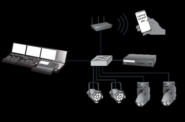
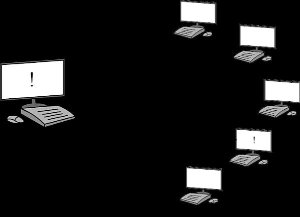
Example Ligh�ng Network
�is example lighting network for a simple system installed in a small venue is a mixture of both approaches, connecting a control console with several lights and a wireless remote phone app, and also transporting data to a gateway for traditional DMX control:
Sound Networks
As sound systems moved from analog to digital in the late 1990s, digital audio started to be transported over standard networking equipment, and this led to the eventual development of proprietary media networking approaches like Audinate’s Dante®, or open approaches like AES-67 and the multi-named AVB (Audio Video Bridging) / TSN (Time-Sensitive Networking) / “Milan®”. In addition, networks are used to transport a number of proprietary audio control systems implemented by manufacturers, as well as open control standards like OSC (Open Sound
Control), MIDI (Musical Instrument Digital Interface) and AES-70 (Open Control Architecture).
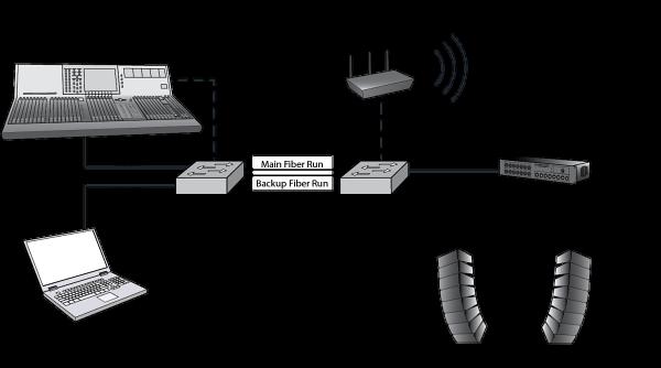
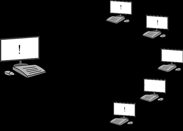
Example Sound Network
In this example sound network for a one-o� show, we share some networking hardware to transport two separate networks; one carries remote control data for the console; the other transports digital audio:
Video Networks
As computing power increased in the late 1990s, networks started being used widely as the control and distribution backbones of many video systems. And then in the 2010s, as a�ordable networks became capable of carrying and routing high-resolution digital video signals, open standards like SDVoE (Software De�ned Video over Ethernet) and SMPTE 2110 were developed.
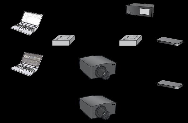
Example Video Network
�is example video system for a permanent show in a museum is actually made up of two physically-separated networks: one for control and one for distribution of the high resolution video signals; some devices connect to both networks via separate physical connections.
Scenery Networks
In scenic automation and rigging systems, networking started being used in the late 1990s to transmit control data between various controllers, input/output (IO) systems, and controlled devices; much of this is done via proprietary approaches from a single manufacturer, and this closed approach is often used to implement safety-rated connections. In addition, for simpler applications, protocols adapted from the days of serial, point-topoint connections like ModBusTCP are used. And as networks became ubiquitous, approaches to share positional data safely between systems, such as RTTrPM (Real-Time Tracking Protocol - Motion), became available.
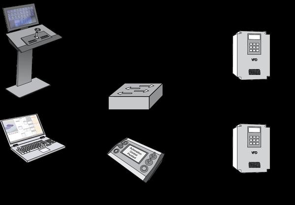
Example Scenery Network
Scenic automation systems typically draw on the world of industrial controls, which, like the entertainment industry, builds on top of Ethernet as a backbone. �is simple scenic automation system connects a controller, a remote pendant, a computer for display and editing of cues, and two drive units:
Networks for Pyro, Costumes, Props, Show Control, You Name It!
Networking presents such a powerful and a�ordable infrastructure that it is the obvious choice to carry just about any kind of digital data. You will �nd it in one form or another behind all kinds of systems throughout live shows. In addition, networks are ideal for show control applications, which connect together two or more entertainment control systems (lighting, sound, video, etc.), allowing the connected systems to synchronize or interact3 .
Keep these systems and applications in mind as we work through all the underlying details of networks; we will revisit, expand on and explain each of these example networks outlined above in the �nal chapter of this book (see the example systems on page 83).
NETWORK TYPES
We can break down networks into two basic types: Local Area Network (LAN) and Wide Area Network (WAN).
Local Area Network (LAN)
A Local Area Network (LAN) covers a “small area, ” ranging from two devices up to a single building or a small group of buildings, and is typically owned and maintained by one organization. Most show networks are LANs.
Wide Area Network (WAN)
A Wide Area Network (WAN) covers long distances, a wide area, or a
broad geographic area. Of course, the best known usage of a WAN is to connect to the Internet. WANs typically use a “ common carrier” such as a phone company for some or all of their connections and, therefore, are rarely entirely owned and operated by a single organization. WANs are a separate area of specialty, mostly outside of the scope of this book, and are rarely used for live entertainment applications except in the largest applications (e.g., a theme park).
Internet
�e Internet is basically a network of networks. To the user, the Internet appears to be one giant network; but, in fact, the user ’ s network, through their Internet service provider (ISP), is simply connected to many other private and public networks. �e Internet Protocol (IP, page 36) is the basis of this system.
NETWORKING CONCEPTS
Before moving on to some practical concepts, let’s go through some abstract, but important networking concepts.
Bit Rate/Bandwidth
A digital data link carries a binary4 stream of 1s and 0s. �e rate of transmission is known as the bit rate, which is measured in bits per second (bit/s, or BPS). Bit rate measurements use the International System of Units (SI) pre�xes, so it’s very common to see something like Mbit/s, a megabit (1 million) per second, or Gbit/s, a gigabit (1 billion) per second. Whatever the transmission medium, there is always some limit as to how much data a single communications connection can handle; this capacity is known as the channel’s bandwidth. A “high bandwidth” connection can carry more than a “low bandwidth” link.
Determinism
All networks have some transmission latency (delay), and in the wider Information Technology (IT) industry, if a web page is a bit slower to load today than it was yesterday it’s an inconvenience. But in our industry, a delayed light cue could expose the workings of a magic trick, and ill-timed, stutter-y audio or video could ruin a live concert. So, the timely delivery of data as a critical need is one of the things that sets our industry apart from the larger business networking world, and it drives the way we design and
con�gure our networks. Data communications systems that can deliver data in a predictable amount of time are said to be deterministic. Actually guaranteeing a delivery time can involve complex systems; in many cases, “good enough” delivery time is more than adequate for the task, especially when we are sending relatively small amounts of data over systems with a very large available bandwidth.
Data Encoding
To allow systems to communicate over a network, we must �rst agree on the way that machines model and represent the physical world, and make sure that all devices communicating with one another use an agreed-upon approach. For speci�c kinds of data like audio samples, “Light Cue 13 Go,” or “platform move at 66% speed,” there are speci�c standards5 . However, deserving a mention here are three interrelated, open data character encoding standards prevalent in the world of networking: the American Standard Code for Information Interchange (ASCII), Unicode, and the Universal Character Set’s (UCS) widely used UTF-8 variant.
ASCII (pronounced ASS-kee) was standardized in the early 1960s, and is basically a grown-up version of a communication game you may have played as a child: substituting numbers for letters of the alphabet in order to send coded messages. For example, to send the text “Ethernet” in ASCII, the following decimal and hex6 numbers would be used:
ASCII was, and UTF-8 is now, one of the most widely-used standards in computing and networking, and many other standards reference or use them. UTF-8 and Unicode are backwards compatible, and in basic control systems we ’ re likely to be using pretty simple characters, so most people call just this standard “ASCII”7 .
Error Detec�on
No communications link is perfect; there is always some possibility of an
error occurring in the transmission—whether caused by noisy lighting dimmers or a loose connector. Error detection schemes add some data to the information traveling over the link, and o�er the receiver a mechanism to determine if the data was corrupted during transmission (or storage). �e Cyclic Redundancy Check (CRC) approach, which is included in Ethernet, is an extremely e�ective error-detection method, with accuracy approaching 100% in many implementations. Basically, with the CRC approach, the data to be checked is treated as a block of bits, which is divided using a specially designed polynomial. �e result of the division is transmitted along with the data for veri�cation by the receiver. If the receiver detects some corruption, it can request for the data to be resent, or discard it.
PACKETS AND FRAMES
In “old school” analog or point-to-point digital connections, a continuous, physical data communications pathway exists between two (or a few) communicating devices, which simply sends voltages representing information back and forth. Networks, on the other hand, share a common physical infrastructure to create virtual connections, so the data tra�c must be managed, or packaged, in some way. �e most typical approach is to break the data up into packets or frames with each unit containing a small chunk of the larger data stream. (Whether a data unit is called a packet or a frame depends basically on what layer it occupies; more on that shortly on page 15). �e packetized nature of networks adds another level of complexity, since it’s possible for packets to arrive at the receiving node delayed, out of order, or corrupted. Higher-level protocols are required to handle these issues, but the bene�ts of �exibility and sophisticated crosssystem interoperability far outweigh the drawbacks.
Packet Forwarding
Packets on a network can be delivered in di�erent ways, depending on the application, and the network components can make a decision on a packetby-packet basis whether to forward (or not) a packet to a particular interface. �e three basic delivery types we will cover are unicast, multicast, and broadcast. �e di�erent approaches can each have a place in a network, depending on what is needed, and networks can operate in di�erent modes
at di�erent times, broadcasting data at some times, multicasting at others, and then unicasting as well.
Unicast
Unicast delivery simply means that packets from one sender are forwarded through a network to a single destination.
Mul�cast
When data is forwarded from one transmitter to two or more receivers simultaneously, this is called multicasting. Multicast communications on a network maximize e�ciency by allowing the sender to send a particular packet of data only once, even though the data is delivered to multiple receivers.
Broadcast
Broadcast delivery is where data is sent to every single connected device (or network segment, see “Broadcast Domain” on page 63). �is approach is very simple and e�ective. On the other hand, broadcasting is ine�cient, since every packet uses network bandwidth and receivers that don’t need the data still have to deal with it.
NETWORKING USING ELECTRICITY
�e most common physical networking method is the transmission of electricity over wires, with the state of the circuit’s electrical signal representing (and communicating) the 1’s and 0’s that make up the digital data. �is approach is cheap, reliable, well understood, and easy to install and troubleshoot.
TIA Category Cables
Networks transmit at high transmission rates, and the construction and installation of the cable is a critical part of the networking system. Cables for networking are grouped into “categories” generally standardized by the Telecommunications Industry Association (TIA).
Category 5e
Category 5e or “Cat 5e” cable8 is widely used. While the “ e ” in Cat 5e cable indicates some enhancements over the older and now obsolete Category 5 cables, the cables are sometimes just referred to as “Cat 5”. First standardized in 2001, Cat 5e allows 100 meter runs of Ethernet speeds up to 1 Gbit/s (with some higher rate, special uses possible). With 1 Gbit/s capacity, Cat 5e o�ers enough bandwidth for all but the most demanding show networking applications. And while typical Cat 5e cable is very di�cult to coil for show purposes, show-oriented cable versions are available.
Category 6
Category 6 is backwards compatible with Cat 5/5e, and designed to handle 1 Gbit/s and shorter runs of 10 Gbit/s.
Category 6A
Category 6A is backwards compatible with Cat 6, and features more stringent cable construction requirements, can run 10 Gbit/s Ethernet at 100m distances.
Category 7/8/etc.
Cable construction is an ever-escalating race, and with Cat 7 and above, it’s getting so application speci�c that you are not likely to encounter it on most show networking applications. If you ’ re needing these levels of bandwidth, you should contact the manufacturer of the gear you are connecting and see what they recommend. But also keep in mind that some of these super high bandwidth connection methods may be overkill and can create additional complexity if you ’ re not in need of the features. Cat 5e is just �ne for many types of networking.
Shielded or Unshielded Cables
Twisted pair cable,9 made of pairs of two wires twisted tightly together, works especially well with the kind of di�erential, balanced transmission used for noise rejection in high-speed digital transmission. �is type of twisted pair cable, without a shield, is called Unshielded, Twisted Pair (UTP). UTP is cheap, e�ective, and easy to install, and is used in many networks.Adding a shield to the cable—such as metal foil or a braid of tiny conductors—can o�er additional resistance to electrical noise, and also reduce the amount of noise emitted from the cable. �is type of cable is known as Shielded, Twisted Pair (STP).
Solid or Stranded Conductors
Networking cable is available with either solid or stranded conductors. Solid conductors are easier to terminate in jacks and generally lose less signal; of course they also make cables nearly impossible to coil (and repeated �exing of solid conductors can cause them to break). For these reasons, solid cables are generally used for permanent installation, while stranded cables are used for temporary patch and connection cables.
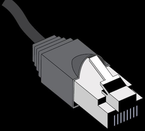
RJ45 (8P8C) Connectors
Networks mostly use the connector shown, which is an 8P8C (eight positions, eight conductors), but is more widely (although technically incorrectly) referred to as an RJ45, available both in plug and jack form. RJ stands for “registered jack,” and the RJ series connector, which was developed by the telecommunications industry, speci�es both the connector and the wiring con�guration. �e 45 variation was originally designed as an 8-position connector carrying (in some applications) only a single pair of
wires, but it looks very similar to the 8P8C connector speci�ed for Ethernet. �e actual telecom RJ45 connectors and con�guration are now obsolete, but the 8P8Cs are almost universally referred to as RJ45s. Because of this, I will refer to these connectors as RJ45 (8P8C) throughout this book.
�e RJ45 (8P8C) has eight pins and can connect four pairs of wire. RJ45 (8P8C) connectors are made of easily-shattered plastic, and are not well suited to the backstage environment. However, they are extremely inexpensive and can be easily installed in a few seconds with “crimping” tools. Some available varieties of these connectors have small ramps on either side of the release tab, protecting them when a cable is pulled through a tangle. In addition, the industrialized Ethercon® connector from Neutrik and other similar connectors are available for our heavy-duty applications.
TIA-568 Cabling Standard
�e TIA-568 standard speci�es a “structured” layout of network wiring for a building. �e standard is very complex, but basically it takes a typical multistory o�ce building and breaks its cable infrastructure into “vertical” and “horizontal” runs. Vertical cables are high-bandwidth “backbones,” which connect through network distribution systems to a �oor’s individual “horizontal” lines (limited to runs totaling 100 meters or less). �e horizontal cables are sometimes run through air-handling plenums, so a type of cable for this application is often called “plenum” cable. �e vertical cables may run through cable risers in buildings, and because they run vertically, “riser” cables must have a high �re resistance rating. Installing a permanent network-based cable system is not something that a casual user should attempt without some research and experience; and of course there are capable contractors who also have the test equipment needed to certify the installation. Further details of the 568 standard are outside the scope of
this book, but there is one important aspect you may encounter: the pin designations in the standard.
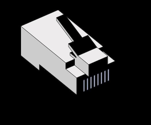
T568A and T568B for RJ45 (8P8C) Connectors
�e wire pair and color code pinout on RJ45 (8P8C) connectors is perhaps the best-known aspect of the 568 cabling standard, and also is perhaps the most confusing. �e 568 standard designated two pin outs for RJ45 (8P8C) connectors: one called T568A, and the other called T568B. On the RJ45 (8P8C) plug, the pins lay out as shown in the graphic.
Cat 5e cable is the most widely used cable with this sort of connector, and has four tightly twisted pairs of wires. To accommodate fast network speeds, the physical con�guration of the wire pairs is critical, and this explains the seemingly strange pinout speci�ed in T568A and B.
�e �rst pair of wires is in the center of this family of connectors (to give some backwards compatibility to pair 1 on RJ11 and similar connections). �e second pair splits across the �rst, and then both wires of pairs 3 and 4 are adjacent and out toward the edges of the connector (they could not continue the splitting scheme further due to crosstalk and other issues). �e only real di�erence between the T568A and T568B schemes is that two pairs are swapped; so, if you are wiring a facility, it really doesn’t matter (functionally) whether you use A or B, as long as you use the same standard on both ends of every cable. �e vast majority of entertainment applications use the T568B pin out:
4 Ring Brown solid
Here is the standard for the less common “A” pin out:
green stripe
orange stripe
Ring Brown solid
NETWORKING USING LIGHT
Instead of sending electrons over wire to send data, it is possible to turn on and o� a light source to represent the data bits being transmitted.
Fiber Types
While it’s possible to send data using light through the air, it is typically more useful in show networking applications to send light through a glass or plastic optical �ber. Light travels down a length of this �ber-optic cable by bouncing back and forth o� the boundary edge between the center glass or plastic and the air, or between the center and a jacket known as the cladding, or bu�er.
Fiber comes in two types: multi-mode and single-mode. Multi-mode allows multiple “modes,” or pathways, for the light to bounce. Single-mode allows fewer possible pathways for the light beam, which leads to fewer bounces, which in turn leads to less loss. �ese characteristics allow extremely high bandwidth, but single-mode �ber is more di�cult to terminate, needs more accurate end alignment, and is therefore more expensive to use.
Because �ber carries only light, �ber-optic data links are completely immune to electrical interference. Potential bandwidth in �ber is extremely high, but this high bandwidth and noise immunity comes at a price: Compared to wire, �ber-optic cable is more expensive and more di�cult to terminate. So, while �ber has become more common in our industry, it’s still usually installed only when high bandwidth, very long cable runs, or extreme noise immunity is required.
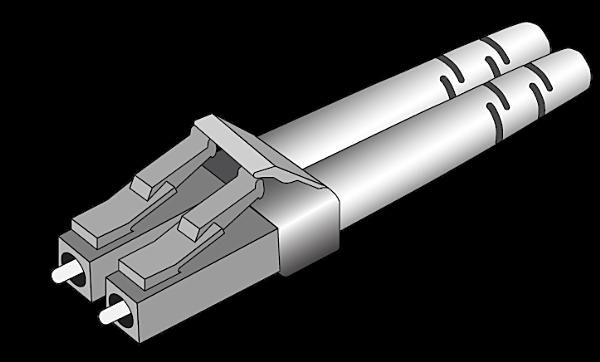
Connectors
A variety of �ber connectors exist; in the 2020s, the most common �ber connector in our industry has been the LC type. LC-Duplex is a pair of LC connectors.
Small Form-Factor Pluggable (SFP) Interfaces
Fiber is often used to connect networking equipment together, and �exible
Small Form-factor Pluggable (SFP) interfaces allow either copper or �ber connections directly to equipment. For some high bandwidth applications, SFP and higher rate SFP+ connections can also be used directly.
NETWORKING USING RADIO
�e third way to transmit data is to use radio signals to encode the 1’s and 0’s of the data. �e most common radio data transmission we are likely to encounter is IEEE 802.11 “Wi-Fi,” which is covered on page 30. Also, there are some commercial approaches to transmitting DMX over a spread spectrum signal (see “Wireless DMX Transmission,” on page 239).
However, because of the potential for radio interference and many failure modes, RF links are rarely as robust as wire or �ber-optic links, so I still advise using copper or �ber if at all possible and radio of any variety only when there is no other practical option.
LAYERING
Let’s bring this all together by taking a step back, and look at the process of network communication through a wider lens. Many older standards commonly used in the entertainment industry specify the details of everything needed to establish communications: the physical connections (voltages, connectors, interfaces, etc.), data transmission details, and the commands (“Go”) or data format. Control and distribution standards developed in the era of the network, however, generally only specify the higher-level details, and leave details of transmission to independent, underlying technologies.
Key to this approach is a concept called “layering.” In a layered communications system, the communication tasks are broken down into component parts. Let’s imagine a network modeled using a simple, hypothetical three-layer system, with the layers called “Application,” “Transport,” and “Physical.”
�e Application layer contains the system processes that interface with the user or control or media system; Transport ensures that the messages get from one place to another, while keeping them intact and in order; and Physical speci�es the interface type, the type of connectors, bit rate and other similar details. With this layered control approach, the data passed to other layers is typically encapsulated into another protocol, with additional
information added as a “ wrapper ” , including things like protocol type, source and destination addresses, etc.
�e tasks of each layer are compartmentalized and independent, since each layer only needs to know how to talk with the layer above it and the layer below. For example, the Application layer really doesn’t care about the details of how its messages get from one machine to another; it simply has to receive its data from the user and then present it to the Transport layer (and vice-versa, of course). �e transport layer doesn’t know anything about the actual connectors, and it doesn’t make any di�erence if the signal is traveling over a wired or wireless link or a �ber-optic cable. It simply needs to know how to talk to the Physical layer, which takes care of all those details. In addition, this layered approach gives us modularity; if we want to change one layer we can leave the rest intact. And protocols and approaches developed using this scheme allow us to easily build on other, widely used, standardized building blocks, saving us time and simplifying the entire process.
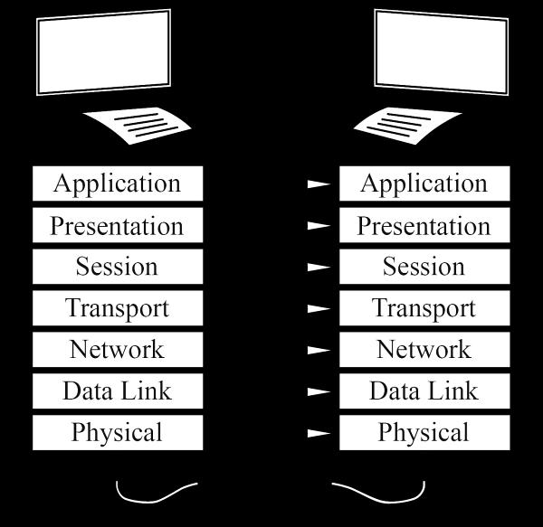
Open Systems Interconnect (OSI) Model
With the basic concept of layering introduced, let’s look in more detail at the most widely used approach, the Open Systems Interconnection (OSI) model. �e OSI model consists of seven discrete layers, each performing one part of the communications and networking task, building on the services o�ered by the next lowest layer. �e approach is complex and represents an idealized model; some network systems combine or leave out layers altogether and do not strictly follow the model. However, OSI is a helpful tool for understanding the functions of networks, and you may hear its terminology used in descriptions of network hardware and design, so a brief description is included here.
�rough OSI, a layer in one device can e�ectively communicate with its counterpart layer in another device on the network, even though the only actual physical connection between the two devices is the physical layer. .
OSI is incredibly powerful but can also be confusing—it is often di�cult to discern separate functions for some of the layers, especially the ones near the middle. Fortunately, as end users, we are generally able to leave this task to our equipment manufacturers and protocol designers, but it is important to understand the concepts, so a brief introduction to each of the OSI layers is o�ered here.10
7 Applica�on
�e application layer, the “highest” layer in OSI, is where the meaning of data resides, and this layer presents resources for applications programs run by users. A web browser, for example, can be thought of as occupying this layer.
6—Presenta�on
�e presentation layer is responsible for presenting the raw data to the application layer; �le and data transformation and translation are the responsibility of this layer, allowing di�erent applications to access the same network. Encryption, for example, could be placed in this layer of the model.
5—Session
�e session layer is responsible for managing and synchronizing the overall network conversation, or “session.” Some of the more advanced protocols in