Visit to download the full and correct content document: https://ebookmass.com/product/energy-and-motorization-in-the-automotive-and-aeron autics-industries-francois-malburet/
More products digital (pdf, epub, mobi) instant download maybe you interests ...
Cuckoo in the Nest Fran Hill
https://ebookmass.com/product/cuckoo-in-the-nest-fran-hill/
Nanotechnology in the Automotive Industry Ghulam Yasin
https://ebookmass.com/product/nanotechnology-in-the-automotiveindustry-ghulam-yasin/
Innovation in the Cultural and Creative Industries Pellegrin-Boucher
https://ebookmass.com/product/innovation-in-the-cultural-andcreative-industries-pellegrin-boucher/
Green Energy to Sustainability: Strategies for Global Industries Hideaki Yukawa
https://ebookmass.com/product/green-energy-to-sustainabilitystrategies-for-global-industries-hideaki-yukawa/
Biobased products and industries Galankis
https://ebookmass.com/product/biobased-products-and-industriesgalankis/
Waste Management in the Chemical and Petroleum Industries 2nd Edition Alireza Bahadori
https://ebookmass.com/product/waste-management-in-the-chemicaland-petroleum-industries-2nd-edition-alireza-bahadori/
Applications in Energy Finance: The Energy Sector, Economic Activity, Financial Markets and the Environment Christos Floros
https://ebookmass.com/product/applications-in-energy-finance-theenergy-sector-economic-activity-financial-markets-and-theenvironment-christos-floros/
Entrepreneurship in the Creative Industries. How Innovative Agents, Skills and Networks Interact Phillip Mcintyre
https://ebookmass.com/product/entrepreneurship-in-the-creativeindustries-how-innovative-agents-skills-and-networks-interactphillip-mcintyre/
Governing for Health: Advancing Health and Equity through Policy and Advocacy Fran Baum
https://ebookmass.com/product/governing-for-health-advancinghealth-and-equity-through-policy-and-advocacy-fran-baum/
Energy and Motorization in the Automotive and Aeronautics Industries
Energy and Motorization in the Automotive and Aeronautics Industries
Tomasz Krysinski
François Malburet
First published 2020 in Great Britain and the United States by ISTE Ltd and John Wiley & Sons, Inc.
Apart from any fair dealing for the purposes of research or private study, or criticism or review, as permitted under the Copyright, Designs and Patents Act 1988, this publication may only be reproduced, stored or transmitted, in any form or by any means, with the prior permission in writing of the publishers, or in the case of reprographic reproduction in accordance with the terms and licenses issued by the CLA. Enquiries concerning reproduction outside these terms should be sent to the publishers at the undermentioned address:
ISTE Ltd
John Wiley & Sons, Inc.
27-37 St George’s Road 111 River Street London SW19 4EU Hoboken, NJ 07030 UK USA
www.iste.co.uk
www.wiley.com
© ISTE Ltd 2020
The rights of Tomasz Krysinski and François Malburet to be identified as the authors of this work have been asserted by them in accordance with the Copyright, Designs and Patents Act 1988.
Library of Congress Control Number: 2020935303
British Library Cataloguing-in-Publication Data
A CIP record for this book is available from the British Library
ISBN 978-1-78630-572-5
1.1.3.
1.2.
1.2.1.
1.2.2.
2.2.1.
2.2.2.
2.3.
2.3.1.
2.3.2.
2.3.3.
2.3.4.
2.4. Internal combustion engine pistons
2.4.1. Theoretical thermodynamic cycles
2.4.2. Real cycles ..................................
2.5. Conclusion ....................................
Chapter
3. Power Transmission Elements
3.1. Transmission system for rotating wings ...................
3.1.1. Conventional helicopters
3.1.2. The case of multi-rotor structures
3.2. Transmission system for aircraft
3.2.1. Propeller aircraft cases
3.2.2. Turbojet aircraft ...............................
3.3. Transmission system for the automotive industry
3.3.1. Gasoline or diesel internal combustion engines
3.3.2. The case of electric motors ........................
3.4. Conclusion ....................................
Chapter
4. Energy Storage .............................
4.1. Classification of energy sources
4.1.1. Primary energy sources
4.1.2. Energy carrier concept
4.1.3. Use of different energy sources in automotive and aeronautical transport .............................
4.2. Energy storage for transport ..........................
4.2.1. Different forms of energy storage ....................
4.2.2. Different energy storage technologies ..................
4.3. Forms of hydrogen storage ...........................
4.3.1. Storage in gaseous form ..........................
4.3.2. Storage in liquid form ...........................
4.3.3. Storage in solid form ............................
4.3.4. Comparison of diesel fuel tanks and automotive batteries
4.4. Conclusion ....................................
Chapter 5. Hybridization ..............................
5.1. Hybridization of electric motors: range extender ..............
5.1.1. Application examples for the automotive industry .......... 222
5.1.2. Application examples for aeronautics .................. 229
5.2. Hybridization of combustion engines: improving energy efficiency .. 232
5.2.1. Interest in parallel hybridization .....................
5.2.2. Classification of electrical hybridization: the case of the automobile ..................................
5.2.3. Implementation of hybridization in the case of the automobile ... 255
5.3. Conclusion .................................... 263
........................................
Foreword
The future of the planet cannot leave anyone feeling indifferent. Environmental problems and more particularly those related to global warming concern us all and require general mobilization. Industries must be particularly active in reducing their greenhouse gas emissions and finding innovative solutions that will enable sustainable, environmentally friendly growth.
The automotive and aeronautics industries have become fully aware of these challenges. Modern vehicles have already made a lot of progress in reducing fuel consumption. The new CAFE (Corporate Average Fuel Efficiency) regulation sets extremely ambitious emission reduction targets for car manufacturers, combined with possible financial sanctions. For aviation, States have made commitments to the ICAO (International Civil Aviation Organization) to stabilize emissions from the sector from 2020 onwards and to even go beyond within the framework of the Paris Agreement, with the objective of reducing CO2 emissions by half by 2050.
Manufacturers today view these topics as an exceptional opportunity to offer innovative technologies, both in terms of vehicle structure and propulsion systems. All potential new energy sources are being explored: biofuels or synthetic fuels, electric or hybrid engines, hydrogen engines, etc.
At least three major challenges must be met in this research for both the automotive and aeronautics worlds: optimizing propulsion efficiency – including engine technology and thrust or traction generation – weight reduction and reduction of forward resistance, both in terms of aerodynamic drag and ground friction.
Throughout the 20th Century, both the automotive and aeronautics industries inspired each other in terms of components and materials as well as means of production. The same type of internal combustion engine, with pistons, has been
x Energy and Motorization in the Automotive and Aeronautics Industries
used in particular in automotive and aeronautical applications for certain small aircraft. Autopilot was first introduced in the aeronautics field and its gradual integration into modern cars with new autonomous driving functions can now be observed. Another example of a similarity between the two industries is the increasing use of composite materials.
This book provides a detailed comparison of energy challenges, with a particular focus on the issue of energy storage – whether it is electric energy or hydrogen –which is one of the main issues for both industries to date.
It shows the major challenge of achieving zero emission cars, helicopters and aircraft. It also allows us to hope that these extremely innovative industries will master the necessary technologies and mutually enrich each other with the experiences and progress made by each other to achieve this goal, thus awakening the minds of the pioneers who have always been able to meet the challenges facing them and enabling these two modes of transport – both of which are definitely part of our modern lives – to build a future for themselves, for future generations, while respecting the planet and its environment.
Guillaume FAURY CEO of Airbus
Preface
“Never believe in any theory until it’s confirmed by experimentation in various conditions and scales.”
Prof. Alexander A. Nikolsky, Department of Aeronautical Engineering, Princeton University
The transport sector represents a significant part of the world’s energy consumption. The technologies used have an impact on the depletion of nonrenewable resources and on the environment, whether it is the air quality (CO2, fine particles, NOx, etc.) or noise pollution.
Beyond organizational and behavioral solutions, the improvement of existing technologies or the development of new technologies is a major challenge for the coming years. After decades of almost exclusive use of fossil energy, the need for energy transition has been recognized. Several solutions, not necessarily new ones, are being developed or considered for the automotive and aeronautics industries: this is the case for electric or hydrogen solutions. It appears that no single solution is likely to offer sufficient potential in the short or medium term to address both the problem of energy transition and sustainable development as well as the issue of mobility, a major challenge for the development of tomorrow’s society (social, economic). It must be considered that each solution will have to be used in the coming decades in a complementary way.
In the above context and on the basis of their professional experience and culture, the authors decided to write this book on energy and the engine power of transport systems in the automotive and aeronautics sector by linking science and technology in an industrial context.
Energy and Motorization in the Automotive and Aeronautics Industries
This book is intended for students of engineering schools, students in mechanical faculties, young engineers involved in companies in the automotive or aeronautics sector and people wishing to have a more global vision on the subject.
A large number of books have been written on the field of energy, each in its own specific field. Similarly, there is a number of structures dedicated to the automotive and aeronautics industries. The authors wanted to write a book that would put the automotive and aeronautics industries into perspective, the needs of which are sometimes similar and sometimes opposite, and whose technical solutions may be similar, even common or, on the contrary, very different. The objective was to present the entire propulsion chain from the product’s energy requirement to energy storage by integrating the engine(s) and power transmission elements.
This book was written with the aim of transmitting a technical culture and know-how in order to support future generations in the development of future solutions. It is the result of a long collaboration between industry and university.
Introduction. This introductory chapter first describes a historical overview of the main technological leaps in the energy field that have made it possible to develop the automobile, the aircraft and the helicopter in recent decades. This overview makes it possible to suggest that – in the coming years – similar transformations such as electrification or the development of urban mobility will represent new challenges facing manufacturers in the aeronautics or automotive sectors. A second part, through a functional approach, introduces Breguet-Leduc’s formulation which at first glance links the characteristics of the structure (aerodynamics and mass) and propulsion energy (electric or fossil fuel) to the distance that can be travelled by the product (a plane, a helicopter or, by extension, a car). This Introduction provides an initial reflection on the product’s structure in terms of its energy consumption as well as on the productivity of the product according to its use.
Chapter 1: Motorization and Reflection on Ideal Engines. This chapter summarizes the methods for obtaining the order of magnitude of the engine power associated with the product and its mission. The first part presents Froude’s theory, necessary for sizing useful hover power of rotary wings, and then justifies the development of useful forward power in flight. The second part details the case of the aircraft by distinguishing the power required for take-off and then for forward flight. The third part introduces the case of the car. This chapter defines an ideal type of engine to meet each product’s power requirements.
Chapter 2: Engine Technologies. As a logical follow-up to the previous chapter, this chapter aims to describe different engine technologies used in aeronautics or automotive applications. The first part describes the operating
Preface xiii
principle of gas turbines and their application to turbo propellers or turboshaft engines that equip aircraft or helicopters. In this context, their thermodynamic cycles and the expression of their yields in relation to the constructive elements are presented. Then, possible improvements of these engines are described by means of exchangers to recover exhaust gases or by an electric hybridization of a turboshaft engine. The second part is devoted to electric motors. After describing different technologies used, several examples of use on cars, aircraft or rotary wing aircraft are proposed. The third part concerns piston internal combustion engines. The thermodynamic cycles of these different types of engines (diesel or gasoline) are presented, as well as a comparison of the performance of these technologies and an introduction to the different technical means of possible improvement.
Chapter 3: Power Transmission Elements. This chapter justifies the need to introduce a fixed or variable reduction in the ratio between the engine and the propulsion element (rotor, propeller or wheels). The first part deals with the case of conventional helicopters and then examines other cases such as multi-rotor systems. The second part presents the case of propeller and then turbojet aircraft. The third part introduces the case of the automobile. For internal combustion engines, gearbox technologies and their staging rules are described. The case of electric energy cars is also discussed.
Chapter 4: Storage. This chapter describes energy storage technologies for transport systems linked to the automotive and aeronautics industries. The first part presents different energy sources available and introduces the notion of an energy carrier. In the second part, the forms of storage used or that are potentially usable on cars, aircraft and helicopters are described. Electrochemical storage (battery), supercapacitors, storage in the form of liquid or gaseous hydrogen, storage in the form of compressed gas, inertial mechanical storage and energy storage in thermal form are thus detailed.
Chapter 5: Hybridization. The purpose of this chapter is to present hybridization and different existing formulas. The first part deals with the use of hybridization to increase the autonomy of the initial propulsion energy (Range Extender). Examples associated with automobile and/or aeronautics are proposed. The second part deals with hybridization of internal combustion engines for the automotive and aeronautical industries. Several specific cases such as parallel or mixed hybridization are developed and given as examples. The chapter concludes with a reflection on hybridization structures.
xiv Energy and Motorization in the Automotive and Aeronautics Industries
Acknowledgements
The authors would like to thank:
– Airbus Helicopters for allowing us to use the knowledge, experience and know-how developed by its employees for the purpose of this book;
– the Airbus Helicopters innovation department team, which provided effective support for some of the carried-out studies;
– the management of the École nationale supérieure des arts et métiers and its development subsidiary AMVALOR, for their collaboration;
– the teachers and students of the École nationale des arts et métiers d’Aix-enProvence who were able to participate in some of these studies;
– Pierre Rougier, flight engineer of the Eurocopter Tiger helicopter, Christian Mercier, chief chain engineer of the Airbus Helicopters hybrid propulsion system, Jan Krysinski, university professor at the Lodz University of Technology, and Philippe Malburet, secondary mathematics teacher, for their careful proofreading and relevant advice in writing this book.
Tomasz KRYSINSKI
François MALBURET
April 2020
Introduction Energy Issues Linked to Transportation Powertrains
The main role of aircraft or land vehicles is transporting a payload (passengers or freight) over a certain distance. This role can be identified according to different mission types: commercial passenger or freight transport missions, military missions with a very specific spectrum or more general use that includes all work activities such as surveillance or rescue as well as individual use for work, leisure or sport.
The choice of the propulsion system’s energy – in terms of being thermal, electric or hybrid – and the calculation of the range or autonomy according to the system’s characteristics (mass, aerodynamic quality, type of power transmission, etc.) are important analyses when comparing modes of transport. Their different adaptations (cars, helicopters, aircraft or compound helicopters) are also important. To do this, it is important to take into account the following aspects:
– The environmental impact of different modes of transport. For aviation, States are committed to the International Civil Aviation Organization (ICAO). The ICAO’s objective is to stabilize emissions from the sector beginning in 2020 and to even go beyond this in the context of the Paris Agreement, by halving CO2 emissions by 2050. In terms of the automobile, the requirements of the Corporate Average Fuel Economy (CAFE) regulations, Euro 6c, or Euro 7, are very strict and can go as far as financial penalties for manufacturers. The new CAFE standard for 2017 to 2025 predicts a reduction in fuel consumption of 5% per year until 2025. These regulations encourage manufacturers to look for new technologies, especially linked to the powertrain electrification.
– Transport safety and security: development policy must lead to a permanent reduction in accident rates and integrate cybersecurity.
xvi Energy and Motorization in the Automotive and Aeronautics Industries
– The market and competitiveness: the proposed solutions must be accessible to a large number of customers.
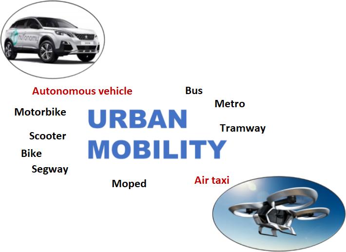
– By 2030, the development of megacities (e.g. London) and congestion in large cities leading to mega-regions (e.g. Johannesburg and Pretoria) or mega-corridors (e.g. Hong Kong or Shenzhen-Guangzhou) will require sustainable mobility strategies to be implemented. The development of new means of transport such as autonomous vehicles or flying taxis based on electrical energy is one of the envisioned solutions (Figure I.1).
Figure I.1. Means of transport within the urban mobility framework (source: Airbus, PSA). For a color version of this figure, see www.iste.co.uk/krysinski/automotive.zip
I.1. History of energies in automotive and aeronautical transport
The availability of energy and the technological maturity of storage systems and engines are the key points that make one technology take precedence over another. Throughout history, different phases have been observed where certain technologies were required and then disappeared in favor of other solutions.
I.1.1. Steam engine
The invention of the steam engine, particularly James Watt’s invention in 1769, led to the development of large ships and railways, such as George Stephenson’s Locomotion in 1825. In terms of use, water vapor required heavy equipment and
Introduction xvii
often numerous personnel. In fact, for aeronautical or automobile transport, these elements were an obstacle for this type of development, even if Cugnot’s fardier (steam dray) (1781) can be considered as the stepping stone to the automobile.
I.1.2. Trial and error
The technologies of electric and internal combustion engines were developed almost alongside each other. Among the different historical dates, we highlight the following for internal combustion engines:
– the first single-cylinder combustion engine designed by Eugenio Barsanti and Felice Matteucci in 1856;
– the two-stroke combustion engine built by Étienne Lenoir in 1859;
– the four-stroke combustion engine invented by Beau de Rochas in 1862, then developed by Nikolaus Otto in 1867 and perfected by Gottlieb Daimler and Wilhelm Maybach in 1887;
– the diesel engine in 1893.
The electric motor – the first developments of which can be traced back to 1881 – was first used in terms of transport for the electric tramway and then for use on an airship in 1884.
The deployment of the gasoline distribution network made a significant contribution to the development of the combustion-powered automobile [LOU 01]. Initially, it was small businesses that were very highly established in society, such as grocery stores and pharmacies, that sold the first quantities of gasoline for cars. Gasoline was initially packaged in 2-, 5- or 10-liter cans, then soon after wooden crates containing ten 5-liter cans were gradually placed at store fronts for public consumption. The American manufacturer Bowser developed the first pumps imported into Europe, which appeared in 1900, mainly among industrial owners of large car fleets.
The First World War marked the massive use of internal combustion engine means of transport, such as trucks, cars, aircraft and field artillery by tractors.
On the commercial side, France welcomed the first gas stations in the early 1920s, marking the beginning of automobile democracy. L’Économique, representing Standard Oil (an American oil refining and distribution company founded by John D. Rockefeller and his associates in 1870), was one of the first to create “service stations”. In 1928, there were between 40,000 and 50,000 fuel sale points, a ratio of one outlet for every 20 cars.
xviii Energy and Motorization in the Automotive and Aeronautics Industries
The 1930s saw the arrival of the first premium fuels. With the help of marketing, “super” fuel became more and more widespread, and by 1934, a third of stations sold it.
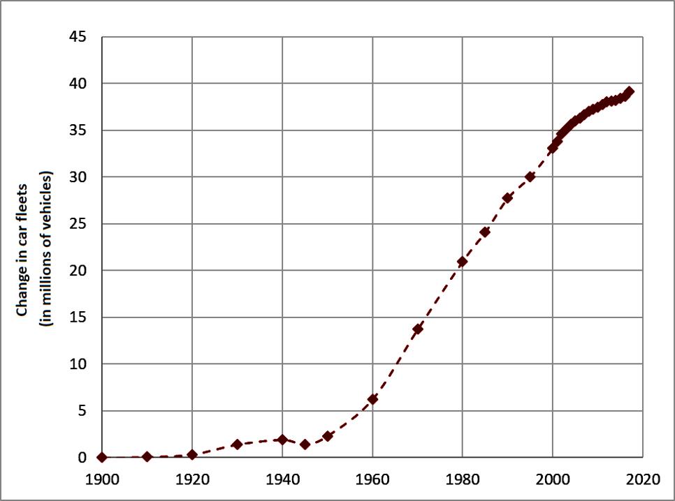
Evidently (Figure I.2), the Second World War impeded the development of vehicles for private individuals since it was not until 1953 that the same number of vehicles returned to pre-war levels. From that date, the number only increased until 2017. From 1953 to the mid-1970s, this was mainly due to household equipment, followed by the rise in households with multiple cars, associated with urban sprawl, the increase in women’s labor rates and the increase in home-to-work travel distances.
Figure I.2. Change in car fleets from 1900 to 2020 (source: Comité des constructeurs français d'automobiles)
This change in the number of cars contributed to the development of the road network. This was achieved thanks to the development of local roads (municipal roads) following the urbanization of society, and infrastructure for rapid longdistance transport. France had 963 km of highways in 1968 and 7,000 km by January 1, 1991; this network continued to grow between 1994 and 2014: 2.5% per year between 1994 and 2004 for conceded motorways, then 1% per year since 2006.
Introduction xix
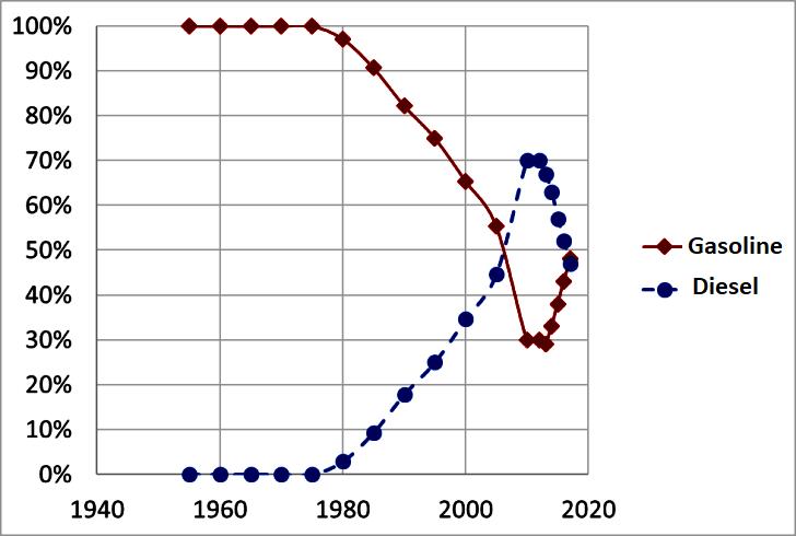
Since the 1960s, the number of private vehicles has increased sharply, and the distribution of diesel and gasoline energy has changed (Figure I.3), particularly in response to the policies and incentives offered by government institutions.
Figure I.3. Evolution of the gasoline and diesel automobile fleet in France (source: Comité des constructeurs français de l'automobile). For a color version of this figure, see www.iste.co.uk/krysinski/automotive.zip
Despite the implementation of a policy encouraging the use of electricity, among other alternative solutions, the market share of these new technologies remained marginal compared to fossil fuels until 2018.
Table I.1. Development of hybridization and electric propulsion in vehicle fleets according to type of energy
In France, the fuel distribution network was estimated at 11,000 stations in 2016, including 6,000 situated along traditional road networks and 5,000 in supermarkets and hypermarkets.
Energy and Motorization in the Automotive and Aeronautics Industries
By comparison – and according to the same logic – the development of electric vehicles requires a major adaptation of the energy distribution system to become a viable alternative to piston-powered vehicles. It will be necessary to introduce a sufficient number of charging sites for individuals (in gas stations, mall car parks and other public spaces) and transport fleets (services, post offices, taxis, business parks, eco-neighborhoods, shared vehicle fleets) with their own charging sites to enable rapid charging. According to the Association pour le développement de la mobilité électrique (AVERE), at the end of 2017 France had 125,000 charging points, 51% were situated on company land, 36% in private individuals’ garages or in collective housing, and 13% were accessible to the public, i.e. nearly 20,000 points spread across the country; the AVERE considers that the number of stations accessible to the public will rise to 100,000 by 2025.
The idea of using the electrical network for vehicle charging, taking into account the growing number of vehicles, the significant recharge time and periods of high vehicle fleet charging demand, leads to a redefinition of the overall strategy for electricity production. Furthermore, it leads, above all, to clever management of vehicle charging over a 24-hour period.
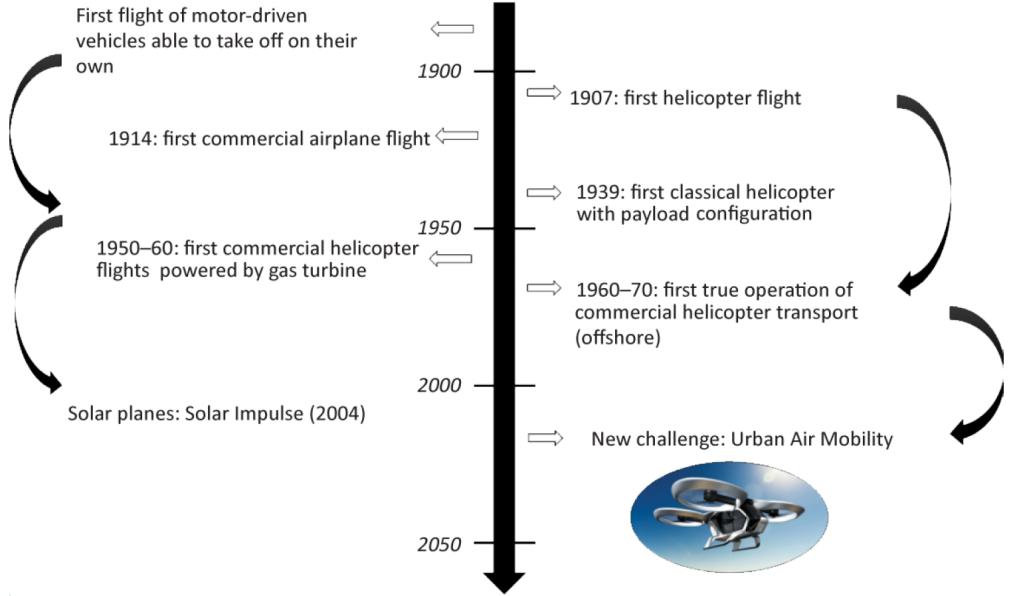
I.1.3. Aeronautics – aircraft
As far as the aeronautics sector is concerned, several key points demonstrate the historical development of techniques and propulsion systems in particular. After a period of trial and error for aerostation and gliding flight, the concept of “heavier than air” led to the first flights of motor vehicles able to take off on their own. First steam engines (Félix and Louis du Temple – 1877), then quickly followed by piston combustion engines [CHA 06].
The First World War marked the launch of the first mass production of aircraft. The inter-war period marked the launch of commercial air transport and, first and foremost, mail transport. This made it possible to develop aircraft and propulsion systems.
This period marked the first aeronautical revolution: on January 1, 1914, for the first time in the history of aviation, a passenger paid for a ticket on the first ever airline. The St. Petersburg-Tampa Airboat Line connected Tampa to St. Petersburg, Florida in 23 minutes. The price of the ticket was $400, the equivalent in 2017 would have been $9,000. This significant cost of the ticket did not prevent the airline from welcoming customers because the amount of time saved by the flight was considerable.
The Second World War was the height of aircraft using a piston engine and a propeller as a means of propulsion. Military aircraft were used intensively in
Introduction xxi
different forms and for different missions: transport aircraft, bombers, reconnaissance aircraft, fighter aircraft, training aircraft, seaplanes, etc. Each of these missions led to different engine power requirements and therefore to improved performance of these technologies.
At the end of the Second World War, the jet engine arrived on the scene. This was the beginning of commercial air transport for regular “all-weather” flights; capable of flying in all weather conditions and achieving the practice of blind flight. It was the era of the jet and then supersonic flight. The first four-engine airliners appeared; the first supersonic civil flight was launched in 1976 (Concorde). Air transport became accessible to all. A century after the beginning of aviation, airlines now transport more than 3 billion passengers per year. In 2017, every minute 52 civilian flights took off from airports around the world
The world's aircraft fleet is expected to double by 2036. From a commercial point of view, since the late 1990s, the market has been dominated by Boeing and Airbus, which are competing in the field of civil aircraft and increasingly in the field of defense. The European manufacturer Airbus estimates that 35,000 new aircraft will have to be produced by then. Boeing is even more optimistic and estimates that 41,000 new aircraft will be needed within 20 years.
We can imagine that the second revolution in aeronautics will be achieved by seeking alternative solutions to the use of kerosene. Pollution and air traffic congestion remain the major concern. ADEME estimates that for a 500 km journey, aircraft can emit up to 241 kg of CO2 per passenger while a car emits about 170 kg of CO2 over the same distance. As there are many more cars than planes, road traffic is by far the most polluting source. In Europe, road traffic is responsible for 72% of greenhouse gas emissions compared to 12.3% for aviation. Despite the upcoming explosion in traffic and aircraft numbers, the air transport industry is nevertheless committed to halving its emissions by 2050 for clean and sustainable aviation. The International Air Transport Association (IATA) intends to stabilize CO2 emissions from the sector by 2020, then reduce them by 50% by 2050 compared to 2005. To achieve this, all solutions must be considered, whether in terms of air traffic management and aircraft performance with more fuel-efficient engines and lighter equipment, not to mention the substitution of all or at least some of the kerosene by a less polluting fuel (biofuel) or energy (electricity).
Since the first oil shocks in 1974, various projects to develop electric motors have been carried out for small aircraft. These include the Solar One project in 1979, the development of HALE-type drones in the 1990s, the Solar Impulse project in 2009 and the Airbus Group E-Fan project, a small two-seater equipped with an electric motor combined with lithium-ion-polymer batteries that made its first flight in 2014. For large aircraft, everything will depend on technological progress in
xxii Energy and Motorization in the Automotive and Aeronautics Industries
storage facilities, electrochemical or hydrogen, whose performance must increase significantly, particularly in terms of the amount of energy stored per kilogram, and on the development of new aircraft architectures to reduce energy requirements during the usage phase.
I.1.4. Helicopters
The first engine to equip a rotary wing was a steam engine that enabled flight at about 10 meters for about 30 seconds, invented in 1877 by Enrico Forlanini. Ten years later, Frenchman Gustave Trouvé launched a model equipped with an electric motor, connected from the ground by thin copper wires for power supply. In 1905, Maurice Léger built an aircraft with coaxial rotors equipped with a 6 hp engine, and brothers Henri and Armand Dufaux successfully achieved vertical take-off powered by an internal combustion engine [BOM 06, BOU 91].
The first “helicopter” flight is often considered to be that achieved by Louis Charles Breguet in August 1907. The vertical take-off aircraft could be converted to achieve horizontal flight using two rotating propellers (gyroplane) and thanks to being equipped with a piston engine [CHA 06]. Collective memory sometimes attributes the first free flight to Paul Cornu in November 1907. The helicopter was equipped with a 24 hp (18 kW) Antoinette piston engine that drove two twin-bladed rotors. The momentum was achieved by means of large belts. The conventional helicopter as it is designed today is unanimously attributed to the Ukrainian-born American engineer Igor Sikorski. His first flight on September 14, 1939, on the Vought-Sikorsky 300 (VS-300), was achieved via a cable end. A 75 hp motor (56 kW) was used to drive the single three-bladed main rotor. In this configuration, a secondary rotor called an “anti-torque” was placed vertically at the end of the tail to compensate for the horizontal rotor’s reaction torque.
Helicopters were first equipped with internal combustion engines with cylinders positioned in a star-shaped or an in-line position, as in aircraft or in automobiles. The Alouette II built by Sud-Aviation was the first production aircraft, from 1955, to be powered by a gas turbine. The first commercial helicopter flight is considered to have been made in June 1949 when the United States Civil Aviation Administration first authorized a helicopter to conduct commercial operations. The first rotations connected partner airports such as Newark International Airport in New Jersey and Long Island International Airport in New York, or San Francisco International Airport and Oakland International Airport. In 1953, New York Airways became the first scheduled helicopter carrier to operate in the United States.
The 2010s saw the emergence of new projects aimed at reducing some of the limits of the classic conventional helicopter formula. The ambition was to increase
the velocity and range of rotating wings while maintaining hover capabilities. The success of the Airbus helicopters X3 prototype in 2010 validated the concept of combining a main rotor with two propellers and two side wings. The RACER (Rapid and Cost-Effective Rotor Craft) project, which is the next step, plans to achieve more than 400 km/h in cruise flight while ensuring a compromise between respect for the environment through low noise emissions and lower fuel consumption, and mission performance. An alternative proposal is presented by Agusta’s tilt rotor formula. The aircraft is made up of tilting rotors allowing the combination of vertical take-off and landing phases (the rotors having a vertical axis to ensure lift), and the forward flight phase (the rotors having a horizontal axis to ensure traction and lift being then provided by the wings). The velocity reached in cruise flight is significantly higher than that achieved in a conventional helicopter. For tilt wings formulas such as the Hiller X-18 (1959) or the Canadair CL-84 (1965), it is the entire wing that tilts with the rotors. They have a similar purpose to the previous formulas, but have not undergone any major developments, as this formula is less effective in hover flight.
In 2012, Pascal Chrétien and Solution F developed the first helicopter in the world to have an electric propulsion. A first hover flight without ground effect with an autonomy of 10 minutes was carried out using a prototype. Another electric helicopter project in the United States was able to fly in September 2016 with a Robinson R44 whose Lycoming Engines IO-540 internal combustion engine was replaced by two electric motors. The prototype was able to fly for 15 minutes with a velocity level of 80 kts. In October 2016, a third prototype of a single-seat electric helicopter with a payload of 115 kg, the Volta, built by a Toulouse-based SME, was able to make its first flights in France. At the same time, Volocopter produced several electric-powered prototypes. The VC2 has 18 propellers with a direct propeller drive motor suspended around an aluminum chassis with a central seat and batteries. The development of electric propulsion leads to the creation of hybrid series solutions (to improve range) combining piston or turbine thermal engines in series with electric propulsion. This type of system aims to increase aircraft autonomy to values that current battery technologies do not allow us to achieve, while having the qualities of electric propulsion (acoustic or consumption) in certain flight phases. Aurora’s XV-24 project is composed of 24 fans driven by electric motors, powered by three generators driven by two Rolls-Royce turboshaft engines. The E-Fan X project by Airbus and Siemens takes this idea up with an aircraft by combining a Rolls-Royce turboshaft engine, a generator and electric motors that drive the propellers.
In conclusion, we can observe that the history of aeronautics is marked by technological leaps that have enabled the product to evolve over relatively long cycles. In the coming years, just as we have seen major transformations in the field of telecommunications and information technology, we can envision similar
xxiv Energy and Motorization in the Automotive and Aeronautics Industries
transformations in the field of transport. In the near future, urban mobility will be defined by a wide range of transport modes, including autonomous air taxis (urban air mobility), which are the new challenges facing aviation manufacturers.
I.2. Functional considerations
The question arises as to how to link the distance covered or to be covered with the characteristics of a propulsion system and the qualities of the aircraft, such as its aerodynamic qualities, its own mass and the useful load to be transported.
The proposed approach enables a first approximation of the range that can be covered according to these parameters. It is based on several concepts defined in the following sections.
I.2.1. L/D ratio
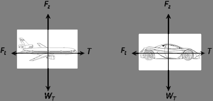
Whatever the transport system, the system’s mechanical balance can be studied by applying the fundamental principle of dynamics. The first approximation is the configuration of a straight horizontal trajectory at constant velocity, level flight for an aircraft, on a slope-free road for a vehicle.
Figure I.4. Evolution of aeronautics
Introduction xxv
The system being studied undergoes: forward resistance actions, weight, traction action related to the powertrain and lift action for an aircraft (aircraft or helicopter), or road reaction for a vehicle (Figure I.5). Initially, all these actions are assumed to apply to the structure’s center of gravity.
The inertia effects are zero at constant velocity. The system’s equilibrium equations are obtained by projecting the fundamental principle of dynamics (FPD) onto the horizontal and vertical axes.
The equations are then:
0= 0= ′ ù = = = [I.1] with:
– Fz: the lift force or vertical component of the ground reaction;
– Ft: the effort of resistance or drag;
– WT: the system’s total weight (M system mass);
– T: the tractive effort induced by powertrain.
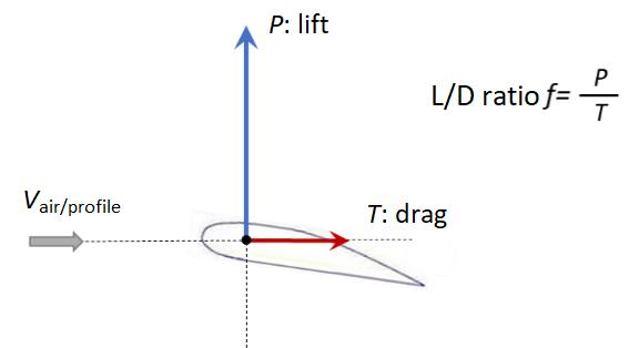
It is common to introduce the L/D ratio f, the aerodynamic characteristic and the dimensionless structural quality of the structure [FIL 12]. For a profile, this translates the ratio between the lift P and the forward resistance force (drag T) (Figure I.6). This concept can be applied to the aircraft model, that is:
[I.2] hence
Figure I.5. Simplified model of mechanical actions on an aircraft or a car
xxvi Energy and Motorization in the Automotive and Aeronautics Industries
Figure I.6. Definition of the aerodynamic L/D ratio of a profile. For a color version of this figure, see www.iste.co.uk/krysinski/automotive.zip
The dimensionless parameter P1 is introduced to reflect the drag ratio relative to the lift, which can also be seen using the FPD as the ratio of resistance actions Ft to weight WT:
= [I.3]
By analogy, the same can be done for a land transport vehicle such as a car. The resistance is then the combination of the aerodynamic drag effects Fra on the vehicle and the rolling resistance actions Frr:
+ = = [I.4]
with:
– Frr: the rolling resistance;
– Fra: the aerodynamic resistance forces on the vehicle;
– Fz: the vertical component of ground reaction forces.
By analogy with aircraft, we obtain:
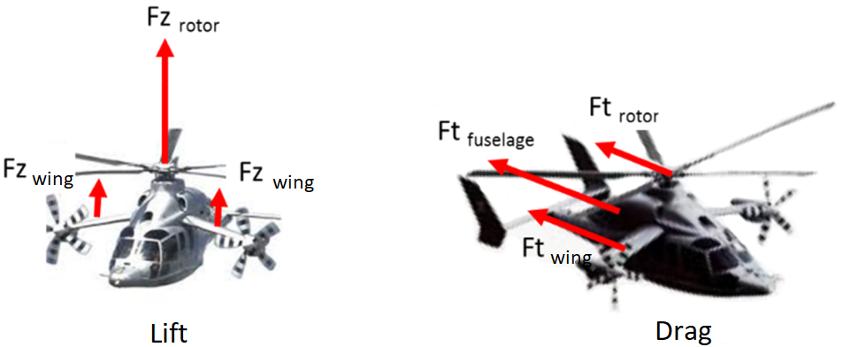
In the case of systems with several lift and drag sources, such as for a combined formula (Figure I.7), it is possible to define by analogy:
Figure I.7. Actions involving a compound helicopter formula (source: Airbus). For a color version of this figure, see www.iste.co.uk/krysinski/automotive.zip
Under these conditions, it is possible to define:
Parameter P1 is obtained by adding up each component’s aerodynamic drag contribution: the fuselage, wing or rotor. We show that the inverse of the overall L/D ratio is the sum of each component’s L/D ratio in the first approximation.
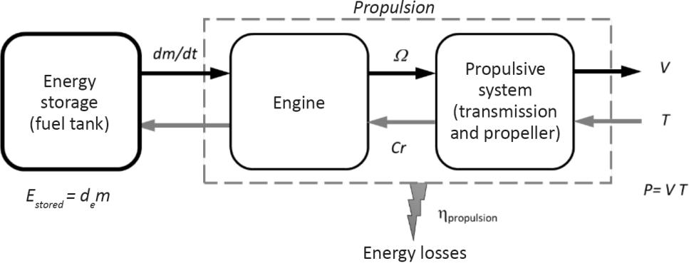
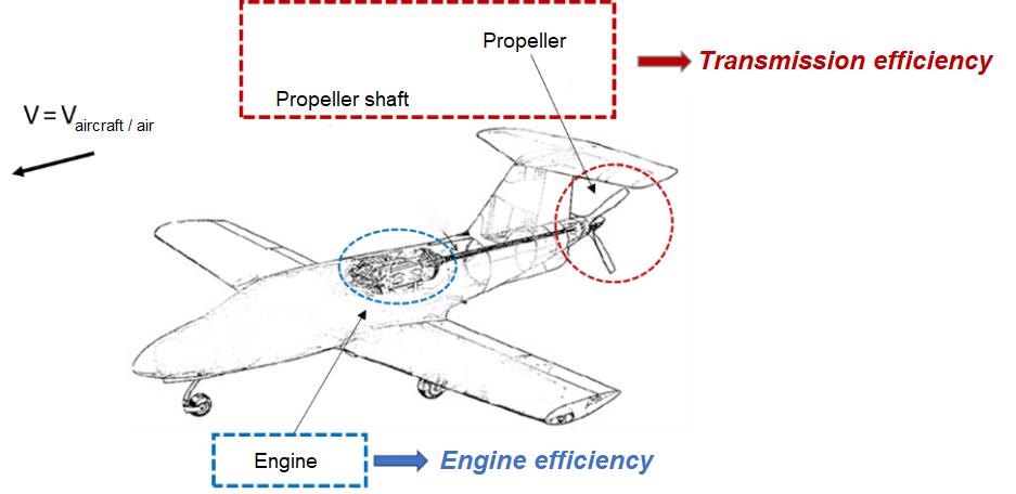
I.2.2. Efficiency and energy losses from the engine to the propulsion system
For all the systems proposed, a propulsion efficiency corresponding to the power ratio supplied by the power system, including the power chain, to the power from the storage system can be defined (Figure I.8) [LEP 91]. This propulsive efficiency includes engine efficiency and propulsive system efficiency.
Figure I.8. Energy consideration and propulsive efficiency
xxviii Energy and Motorization in the Automotive and Aeronautics Industries
By definition, the power supplied by the tank to the engine is given by:
with:
– de: the energy density [J/kg];
– : the mass flow rate [kg/s].
For the field of transport that is associated with energy storage due to the autonomy required, the energy density refers either to the mass energy density [J/kg] or to the volume energy density [J/L]. The higher the energy density, the more energy can be stored or transported for a given volume or mass.
This allows us to define another dimensionless quantity, corresponding to the propulsive efficiency associated with the efficiency of the engine and propulsion system including the power transmission and the system generating the traction (propeller or rotor) (Figure I.9). Let:
Figure I.9. Energy loss and propulsive efficiency. For a color version of this figure, see www.iste.co.uk/krysinski/automotive.zip
This results in:
Introduction xxix
This relationship makes it possible to evaluate the mass flow required to create the tractive effort for a given distance to be covered. It is not generally exploited in this form.
I.2.3. Concept of specific consumption: specific case of the aircraft
Rather than directly assessing fuel flow, the concept of specific fuel consumption, known as SFC, is generally used to specify the mass of fuel required to provide power or thrust in a given time. Depending on the case, it is usually expressed in g/(kW h) or g/(kN s).
The SFC depends on the engine design. Differences in specific fuel consumption between engines using the same technology tend to be quite small. It allows the efficiency of different engines to be compared.
We can thus define: = or = [I.11] or by combining [I.10] and [I.11]:
[I.12]
At constant forward velocity V, the specific consumption is proportional to the velocity and is inversely proportional to the efficiency of the energy chain and the energy density of the fuel.
I.2.4. Breguet-Leduc’s formulation of the range to be covered
The idea is to propose a sizing formula that leads to the analysis of an aircraft’s range according to the system parameters [BOI 98].
A distinction is made between cases where fuel consumption results in a significant reduction in the system’s mass – such as diesel, gasoline or kerosene – and cases where there is no change in mass, such as electric power units associated with batteries.
xxx Energy and Motorization in the Automotive and Aeronautics Industries
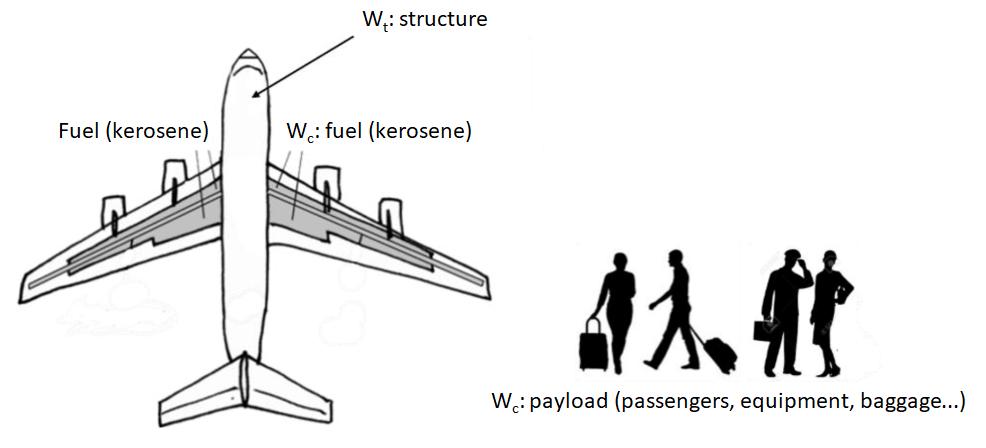
I.2.4.1. System including variable mass energy storage: gasoline, diesel or kerosene
The total WT system weight is broken down into payload, fuel and structure: = payload + fuel + structure [I.13] with:
– Wpayload: the payload’s weight;
– Wfuel: the weight of the fuel to ensure the mission;
– Wstructure: the structure’s weight.
The change in weight is then due to the change in fuel weight during the flight or journey. This is negative. That is, gravity being constant:
= = 0 [I.14]
Taking into account the relationship expressing the conservation of power and introducing the L/D ratio f, we obtain:
= = [I.15]
Figure I.10. Definition and distribution of masses on an aircraft structure
At constant velocity, we obtain by integration:
The final mass at the end of the mission is defined as the structure mass plus the payload, the initial mass being the final mass plus the fuel mass.
By introducing the structure mass Mstructure, the useful mass Mpayload and the fuel mass Mfuel, we obtain the following Breguet-Leduc formula:
By introducing the SFC (see definition [I.12]), the following wording can also be used, which then introduces the velocity reduced to the specific consumption in the formulation:
= 1+
This formulation can also be written using dimensionless coefficients Pi. We note:
In general terms, we could retain that the range, reduced to the energy density of the fuel and gravity, is such that: distance = 1+ [I.21]
with dimensionless parameters:
– P1: coefficient of resistance to forward flight based on weight or lift (similar to the opposite of L/D ratio f);
– P2: engine power and propulsion system efficiency;
xxxii Energy and Motorization in the Automotive and Aeronautics Industries
– P3: ratio of fuel mass to system mass at the end of the mission (structure mass + payload).
The expression of the distance according to these dimensionless parameters shows that it is inversely proportional to the relative effect of the driving resistance brought back to the lift, proportional to the system’s efficiency and above all as a function of the ratio of fuel mass to dry mass (at the end of the mission) through the function ln.
I.2.4.2. A system including constant mass energy storage: batteries
For electric motors, the energy is stored in batteries. Their mass is independent of the charge rate. There is therefore no mass variation during the flight or journey time. The power supplied by the engine is related to the power used to create the tractive effort to obtain a cruising velocity V by:
by introducing the definition of velocity:
By integration, assuming that the velocity is constant, we obtain the range:
By introducing the definition of stored energy, the expression of distance takes the following form:
We note: = [I.26]
By analogy with what has been done in the case of variable fuel mass, we obtain by introducing the dimensionless coefficients: