Computer Modeling in the Aerospace Industry
Edited by Iftikhar B. Abbasov
This edition first published 2020 by John Wiley & Sons, Inc., 111 River Street, Hoboken, NJ 07030, USA and Scrivener Publishing LLC, 100 Cummings Center, Suite 541J, Beverly, MA 01915, USA © 2020 Scrivener Publishing LLC
For more information about Scrivener publications please visit www.scrivenerpublishing.com.
All rights reserved. No part of this publication may be reproduced, stored in a retrieval system, or transmitted, in any form or by any means, electronic, mechanical, photocopying, recording, or otherwise, except as permitted by law. Advice on how to obtain permission to reuse material from this title is available at http://www.wiley.com/go/permissions.
Wiley Global Headquarters
111 River Street, Hoboken, NJ 07030, USA
For details of our global editorial offices, customer services, and more information about Wiley products visit us at www.wiley.com.
Limit of Liability/Disclaimer of Warranty
While the publisher and authors have used their best efforts in preparing this work, they make no representations or warranties with respect to the accuracy or completeness of the contents of this work and specifically disclaim all warranties, including without limitation any implied warranties of merchantability or fitness for a particular purpose. No warranty may be created or extended by sales representatives, written sales materials, or promotional statements for this work. The fact that an organization, website, or product is referred to in this work as a citation and/or potential source of further information does not mean that the publisher and authors endorse the information or services the organization, website, or product may provide or recommendations it may make. This work is sold with the understanding that the publisher is not engaged in rendering professional services. The advice and strategies contained herein may not be suitable for your situation. You should consult with a specialist where appropriate. Neither the publisher nor authors shall be liable for any loss of profit or any other commercial damages, including but not limited to special, incidental, consequential, or other damages. Further, readers should be aware that websites listed in this work may have changed or disappeared between when this work was written and when it is read.
Library of Congress Cataloging-in-Publication Data
ISBN 978-1-119-66131-3
Cover image: Chromakinetic | Dreamstime.com
Cover design by Kris Hackerott
Set in size of 11pt and Minion Pro by Manila Typesetting Company, Makati, Philippines
Dedicated to the 70-year anniversary of the Department of Engineering Graphics and Computer Design
2.3.4
2.4
2.4.4
2.4.5
2.5 Conceptual
2.6
2.7
2.6.1
2.6.2
2.8
2.7.1
2.7.2
2.7.3
2.7.4
2.7.5
2.7.6
2.7.7
2.7.9
2.8.1
2.8.2
2.9
2.9.1
2.9.3
2.9.4
2.9.5
2.9.6
S. Durov 3.1
3.3 Peculiarities of Control of the Vertical Takeoff and Landing Aircraft in the Transitional and Hovering Mode
3.4 Problems of Stability and Controllability of Hydro Convertiplane with Tandem-Mounted Rotors in Rotary Annular Channels
3.5 Cryogenic Turboelectric Aircrafts are a Good Solution for Short-Range and Takeoff Hybrid Airline Complexes
5
Sergey A. Sinutin, Alexander A. Gorbunov, and Yekaterina B. Gorbunova
5.1
5.3
5.4
5.5
5.6
5.7
5.8
5.9
5.10
5.11
5.12
5.13
5.14
5.15
6.2.4
6.3 Purposes and Objectives of the Extravehicular Activity of the RTS Cosmonaut Operator on the ISS in Open Space, Technology of Computer Simulation in the Virtual Reality Environment
6.3.1 Extravehicular Activity of the RTS Cosmonaut Operator 229
6.3.2 Technologies of Methodical and Hardware-Software Implementation of a Cosmonaut-Operator’s
6.3.3 Dynamic Virtual Model of the Manipulator
6.3.4 Software Technologies for the Formation of Dynamic Models of the Editor-Modeler
6.4 Experimental Studies of the Functional Completeness of TMS Graphics and Software
6.4.1 Information and Functional Power of the TMS Visualizer
6.4.2 An Example of a Simulator of a Typical Flight Mission at Solar Battery Installation
6.4.3 The Technology of Testing Emergency Situations
6.4.4
Abstract
This book is devoted to unique developments in the field of computer modeling of aerospace engineering. The book describes the original conceptual models of amphibious aircraft, ground-effect vehicles, hydrofoil vessels, from the idea to the full implementation. The developed models are presented with the design of passenger compartments and are actually ready for implementation in the aircraft industry. The originality of the concepts bases on biological prototypes, they are ergonomic, multifunctional and beautiful. The aerodynamic layout of prospective convertible land and ship-based aircrafts of vertical and short takeoff-landing is presented. The development of the original model of the unmanned aerial vehicle embodied in the material is described; the results of full-scale experiments are presented. The technology of modeling aerospace simulators based on the virtual reality environment with technical vision devices is considered.
The book is intended for researchers and developers in the area of aerospace industry, for aircraft designers and engineering students.
Preface
In today’s world it is difficult to imagine a person’s life without business trips or travelling. Aircraft are often used for this purpose, which is not a surprise. The beauty of the surrounding dark blue sky and the clouds floating below can hardly leave anyone indifferent at an altitude of ten thousand kilometers. Outside the window, the weather is not very changeable, while there may be a thunderstorm, rain or snow on the ground. Aviation attracts not only with high speed and speed of flights, it is used in many areas of daily life. Due to the high maneuverability, versatility, it can be used for civilian, military purposes, for rescue operations, and in extinguishing forest fires. It is for these purposes that amphibious aircraft are the most effective; they are also indispensable for search and rescue operations at sea. In many coastal countries, coastal hydroaviation is very important; in island countries it is simply irreplaceable. Therefore, the design of hydroaviation and amphibious aircraft remain relevant.
The first Chapter of this book is devoted to the use of computer modeling in aircraft construction. The process of designing a conceptually new aircraft “Chiroptera” based on bionic forms is described. Also the conceptual design of the new “Lotos” car is considered. When creating the concept of the car body design, bionic shape of lotus petals was used. For clarity, the scenes of toned three-dimensional models of simulated objects are rendered.
The second Chapter presents a three-dimensional modeling of existing amphibious aircraft Be-200, Be-103, as well as “Lapwing” concept, “Water Strider” ground-effect vehicle, and “Afalina” hydrofoil vessel. The process of designing passenger cabins of aircraft is described. The second Chapter also considers computer simulation of “Sesarma” autonomous mobile robotic system. The renderer is selected and the light sources are installed and the final scenes of realistic rendering are shown.
The third Chapter discusses the various types of aerodynamic layouts and possible applications of modern and advanced convertible land and ship-based aircrafts of vertical and shortened takeoff and landing.
The concepts and requirements for convertible high-speed aircrafts with cryogenic, hybrid diesel-electric and turboprop power units are presented.
The fourth Chapter presents a conceptual model of a multifunctional amphibious aircraft. Brief technical characteristics, visual range and historical aspects of the aircraft creation are presented. The prototype of the amphibious aircraft concept was “Consolidated PBY-5A Catalina”, a modification of the amphibious aircraft of the fifties. In addition to the use for travel and outdoor activities, this aircraft can be used in many other utilitarian purposes.
The fifth Chapter discusses the features of the formation of a mathematical model of an unmanned aerial vehicle with an elliptical wing. In order to create a mathematical model of object control, a number of full-scale models of the unmanned vehicle were created. The results of flight tests of large-scale models of the device are given, characteristic features of management are outlined.
The sixth Chapter discusses the technology of planning and implementation of geometric support of simulator-modeling computer systems that operate on the basis of virtual reality. The basic elements of rational discretization of complex technical objects described by curves and surfaces are given. The software architecture of the simulator-modeling complex with channels of rendering of the virtual environment and technical vision is described.
Prof. Iftikhar B. Abbasov Editor
Computer Simulation in Aircraft
Iftikhar B. Abbasov
Southern Federal University, Engineering Technological Academy, Department of Engineering Graphics and Computer Design, Taganrog, Russia
Abstract
The first chapter is devoted to the use of computer simulation in aircraft construction. The process of designing a conceptually new aircraft based on bionic forms is described. Presents search visual and graphical solutions of the developed model. Three-dimensional modeling of the structural parts of the aircraft was carried out according to draft designs. To simulate three-dimensional surfaces, the Koons method is used. The issues of solid-state modeling of a space rocket using the lofting method and the Be-200 amphibious aircraft were also considered. Also considered is the conceptual design of the new car. When creating the concept of a car body design, a bionic shape of lotus petals is used. Prototypes of car body contours are designed as draft designs. For three-dimensional modeling of structural parts of the car, polygonal extrusion method was applied. A three-dimensional computer model of the developed car concept is presented. For clarity, scenes are presented rendering of shaded three-dimensional models of simulated objects.
Keywords: Conceptual model, flight of bats, three-dimensional modelling, aircraft, car, bionics
1.1 Simulation of Aircraft
To simulate a certain aircraft [1, 34], the graphic system of three-dimensional modeling Mechanical Desktop is used. In this system, it is possible to carry out modeling of both technical objects and elements of the interior or landscape. To create three-dimensional models, the following commands are
Email: iftikhar_abbasov@mail.ru
Iftikhar B. Abbasov (ed.) Computer Modeling in the Aerospace Industry, (1–22) © 2020 Scrivener Publishing LLC
used: _extrude_ (extrusion), _revolve_ (rotation), _sweep_ (bending) and _loft_ (lofting). The simplest and most obvious of the 3D commands is the _extrude_ command. To create a three-dimensional body, a profile sketch is extruded along the third axis for a distance equal to a given body thickness. The profile can be extruded in any direction or in two directions at once (the so-called extrusion from the middle plane). The transformation of the sketch into a three-dimensional model is carried out after some restrictions are imposed on it. The process of imposing restrictions includes creating a profile or imposing dimensional restrictions.
Creating a model consists of several stages:
- at the first stage, we determine the sequence of creation of structural parts and the corresponding methods for this;
- at the second stage we carry out the general assembly and completion of the device as a whole;
- at the third stage, to create a realistic model, we perform toning and final rendering of the model of the aircraft.
At the first stage, we will create an aircraft wing in the form of an oblique wedge surface. To do this, we draw profiles of the wing on the working planes, and the creation of the wing itself is carried out by the loft method (the method of supporting sections). In the three-dimensional mechanical modeling system Mechanical Desktop, the loft method is implemented using the _loft_ command. First we create two working planes and build wing profiles on them, then we translate each figure into a profile, that is, we impose restrictions. After selecting the _loft_ command, we indicate the wing profiles in succession to the request. We create the second wing using the mirror reflection of the built wing and place them along the future fuselage.
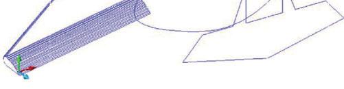
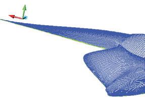
At the second stage, to create the fuselage, we again select the same method of support sections. In this case, the support sections can play the role of guide frames. The result of the construction of the fuselage support sections (four) with wings is presented in the form of a frame model in Fig. 1.1.
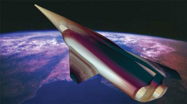
Using the _loft_ command, we build the fuselage surface, and to create a jet engine nozzle, we use the _extrude_ command using the subtraction method. Then, to create realistic scenes of a three-dimensional model, we assign textures and light sources. Next we select the background for the scene as a photograph of the Earth from orbit. The rendering scene is shown in Fig. 1.2. It should be noted that this scene can be modeled in other three-dimensional systems; however, this graphic system allows you to make the design documentation of the object.
1.2 Simulation of Rocket
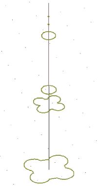
Let’s create a solid model of a rocket using the lofting method [35, 36] in the AutoCAD graphic system. To use the loft method, you must create the initial path of the loft and the cross-section in the form of flat figures. In the top view, with the help of two-dimensional primitives, it is necessary to construct rocket cross-sectional figures; in the front view, the axis of the rocket height is constructed. Further, the cross-section figures will be mixed to the necessary heights, as in Fig. 1.3.
Fig. 1.1 The three-dimensional wireframe model aircraft.
Fig. 1.2 Scene of rendering of the aircraft from the Earth’s orbit.
1.3 Plane figures for lofting.
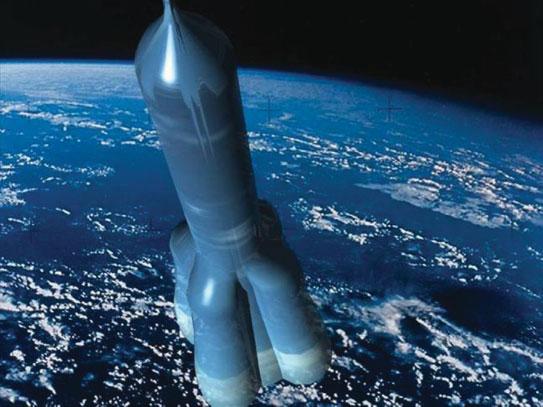
In the three-dimensional view, using the Solid\Loft command, the section shapes in height are alternately selected, and the appropriate antialiasing mode is selected from the Loft Setting dialog box. Fig. 1.4 shows the rendering of a shaded model of a rocket created by the loft method against the background of the Earth.
1.4 Rendering of a shaded solid model of a rocket.
Fig.
Fig.
1.3 Modeling of Streamlined Surfaces
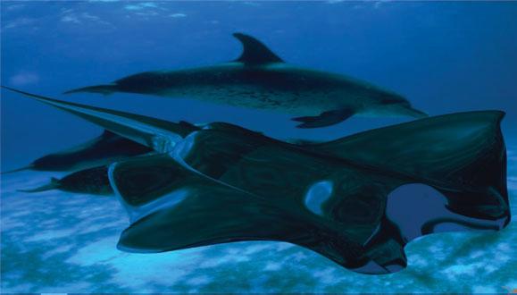
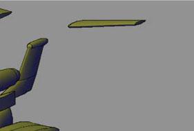
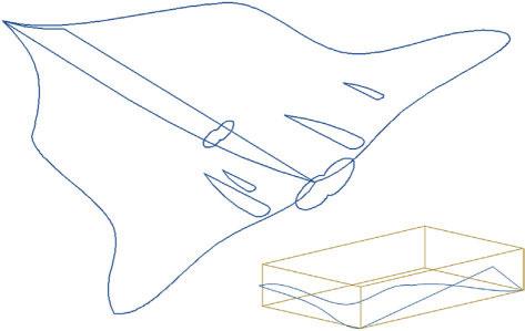
With the help of the graphic system Mechanical Desktop, you can model objects with streamlined surfaces. As such objects, their natural counterparts are most often used, and in our case a streamlined underwater object in the form of a stingray (the so-called “black devil”) will be modeled [37].
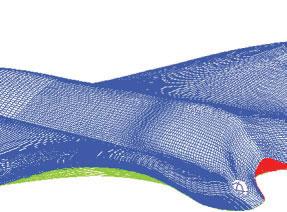
To simulate the surface of the “black devil”, the method of creating surfaces with several generators was used (Fig. 1.5). In the three-dimensional system of Mechanical Desktop with the help of the _edgesurf_ command, you can build unusual surfaces defined by four generating objects. Segments, arcs, splines, and polylines can act as generators. By the command _edgesurf_ a polygonal network is created – the surface of Coons, i.e., surface defined by four faces.
The image of the stingray in the form of a flat spline was inscribed in the dimensional rectangle. Then a dimensional prism was created on the basis of a rectangle; the prism in turn was divided into smaller prisms. In accordance with the image of the stingray, three-dimensional splines were inscribed into these prisms. The body of the slope was divided into several sections, and the wings were mainly built on the whole three-dimensional splines. As a result, a complete object was created by connecting different fragments.
Further, material was assigned to create realistic scenes of a threedimensional model, and light sources were adjusted. Blue chrome was chosen as the basis for the material of the surface of the stingray. Taking into account the specific environmental conditions, the main color, shadows, color of reflection, smoothness of the surface, transparency were corrected. For the reflected color and for the unevenness of the surface, an additional text. map from a separate image was used. After assigning the material, the background was selected as a photograph of an underwater landscape. The rendering scene is shown in Fig. 1.6.
Fig. 1.5 Three-dimensional wireframe model of “Black Devil”.
Fig. 1.6 Rendering of scene with the “Black Devil”.
1.4 Simulation of the Be-200 Amphibious Aircraft
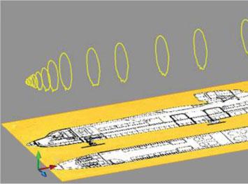
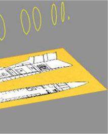
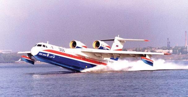
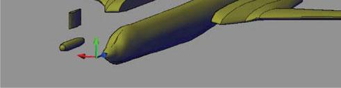
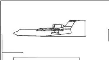
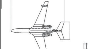
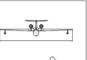
The issues of three-dimensional modeling of the Be-200 amphibious aircraft [2], developed by the Beriev Taganrog Aviation Scientific-Technical Complex are considered. AutoCAD graphical system is used for simulation. The three-dimensional model of an amphibian can be created using solid modeling. This will require some source material in the form of dimensional drawings (Fig. 1.7) and photos of the object being modeled (Fig. 1.8).
To model the aircraft, we divide it into its component parts: fuselage (boat), wing, tail, engines, stabilizers. When modeling, the loft method is
Fig. 1.7 Flat boat shapes based on drawings.
Fig. 1.8 Takeoff of the amphibious aircraft Be-200 from the water.
mainly used. For technological reasons, this is the most suitable method used in both aircraft manufacturing and shipbuilding. Fuselage frames are used as flat sections; the accuracy of the model will depend on their number.
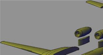
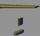
Flat sections can be built on the basis of the spline, and it is necessary to distribute them along the length of the boat. The wing and the tail section are constructed in a similar way. Engines and stabilizers are created by rotating out of a polyline. Fig. 1.9 shows the result of modeling the structural parts of an amphibian based on the original flat forms.
Fig. 1.10 presents a theoretical drawing of an amphibian aircraft, which was automatically built on the basis of the parametric model created. For
Fig. 1.9 Structural parts of an amphibious aircraft.
the development of this design document the graphic system Mechanical Desktop (Autodesk Inventor) was used, which is a three-dimensional add-on of the AutoCAD system.
Fig. 1.11 shows a solid model of an amphibian in the Realistic display mode. Fig. 1.12 presents the rendering of the scene of the amphibian.
Fig. 1.10 Theoretical drawing based on parametrical model.
Fig. 1.11 Solid shaded amphibian model.
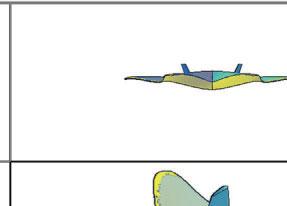
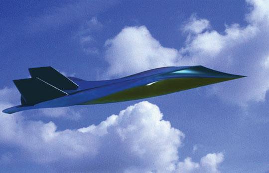
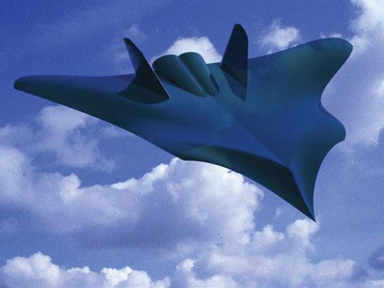
1.5 Conceptual Model of Aircraft “Chiroptera”
Day by day, the necessity of visual demonstration of industrial products under development in different spheres of human activity has been increasing. It is justified from an economic point of view. State-of-the-art technologies of computer modeling and designing enable us to achieve results which engineers could not even dream of a couple of decades ago [3].
Issues of aircraft state-of-the-art technologies of computer modeling and design application are actual. Let’s consider some of the modern literature references in this sphere. The article [4] describes specific features of modern software tools implementation for design objectives. New software possibilities of aircraft structure development are described.
The article [5] is concerned with aircraft conceptual design where birds wing aerodynamic properties are taken into account. In papers [6, 7] the design of economical-to-operate passenger aircraft issues are considered.
The article [8] is concerned with conceptual design of passenger tailless airplane. Different aerodynamic configurations are presented and analyzed. In the paper [9] the conceptual design properties of new generation supersonic aircraft with original arrangement of landing gears and fuel tank are given.
This paper is concerned with 3D computer modeling of new aircraft concept. For aircraft modeling the Koons surfaces method (or Edge Mesh) is used. This method enables the creation of curvilinear streamlined surfaces based on four closed arbitrary 3D splines. Based on analysis of air
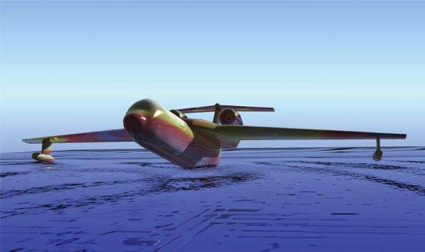
Fig. 1.12 Rendering of a scene from an amphibian aircraft.
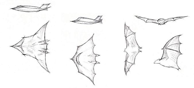
environment natural forms renfering imagery, the aerodynamic characteristics of the only flying mammals – chiroptera seemed to be attractive. Skin stretched between their fingers looks like Koons surfaces built per Edge Mesh.
Wing-handed animals (Chiroptera) – from Greek language χείρ – cheir (hand), πτερόν – pteron (wing) [10]. Chiroptera is the only placental mammal able for active flight. They are divided into two suborders: fruit bats and bats. They are widely spread geographically (except tundra and polar regions). Their main way of travel is a flapping flight. It enables them to use biological resources inaccessible for other mammals. In general, chiroptera feed on insects, small vertebrata, fish and fruits as well. They are active in evening shades and nights; in daylight time they hide in different shelters. That’s why in many cultures chiroptera, especially bats, have a bad reputation and are associated with evil magic and witchcraft.
Speed of their flight depends on wing shape [11]. Relatively high speeds are typical for lunkers who have long arrow-headed wings. Flapping flight for chiropteras is typical but some representatives use hovering and gliding flight. In flight at high speeds the birds can change their wings’ length and square and chiropteras can’t bend wing without all membrane releasing. However, in contrast to birds they can freely change wing profile outline. In the history of world aviation the first attempts to create aircraft were connected with imitation of bird flight. The first time aircraft with a wing like bats was created was by French engineer Clément Ader (1841–1925) [12]. His aerostatic machine was a tailless monoplane without vertical fin. Fuselage and wing frames were manufactured of bamboo silk-fabric covered. The aircraft was equipped with two pusher propellers with four blades, each of which was fitted with a steam engine. He called his aircraft “Eole” in honor of the ancient Greek Olympian Eolus (Fig. 1.13). In October 1890, Ader tried to fly on Eole, which took off and flew about 50 m.
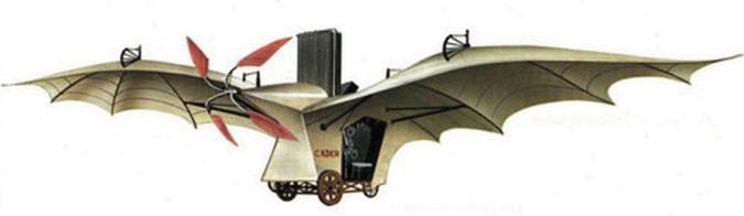
Fig. 1.13 Aircraft K. Adère “Eole” [10].
However, because of the absence of lateral controls he failed to perform a full flight. But it was the first self-moving flight in history, carried out 13 years’ prior to the Wright brothers’ flight.
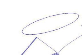
Aircraft conceptual development starts from the creative search stage: choice of style, composite approach, sketch creation, future model draw [13, 14]. In Fig. 1.14 the sketches of natural bionic forms and variants of creative search are shown. High-speed aircraft is assumed to be modeled and therefore as a final variant the construction with extended arrowheaded wing was chosen (Fig. 1.15, left side).
Further, the chosen sketch is modified based on aerodynamic operating characteristics and ergonomic requirements. After that the stage of 3D modeling based on detailed design takes place. In this work, graphic
Fig. 1.14 Variant of creative search.
Fig. 1.15 Original plane forms of aircraft surface.
modeling system AutoCAD will be used. Nowadays there are a fair number of 3D modeling graphic systems and CAD system. Graphic system AutoCAD enables not only the creation of correct drawings, it can also carry out 3D surface, solid modeling and create realistic rendering. It should be noted that the author has considered the issues of amphibian aircraft 3D computer modeling in his papers [15, 38]. In the paper [38] the issues of amphibian aircraft conceptual design based on bionic forms were described.
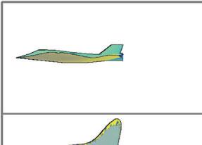
To apply Koons method it is necessary to build overall 3D box [16]. 3D box is constructed by means of rectangle extrusion to some height. On each side edge of 3D box the curvelinear spline per closed loop is constructed (Fig. 1.15, right side, below). With the help of command Edge Mesh the constructed splines are pointed step by step, resulting in a smoothed curved surface.
While creating aircraft it is necessary to analyze the commands of surface modeling available as well as possibilities to design components of the object under modeling. We decompose aircraft (based on airframe axis): airframe upper and lower surface, vertical fin surface and engine surface. For better aerodynamic properties the aircraft airframe should be streamlined and for its creation the method of Edge Mesh will be used. Tail unit and engine nozzles can be created with command Ruled Mesh.
With the help of 3D box, the half of streamlined body along its axis is created. To create a triangle outline of the body upper part it is necessary to shift one of the closed spline peaks inside 3D box. Using Mirror tool, the wing splines mirrored copies are constructed. Original flatness for tail unit and nozzle is constructed in the form of polylines and a spline. The result of preparatory work to create aircraft surface in the form of flat splines and polylines is shown in Fig. 1.15.
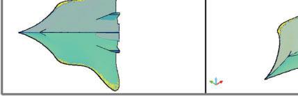
Prior to performing 3D modeling let’s consider design features of the aircraft model under development. Aircraft aerodynamic configuration pertains to “flying wing” type (without fuselage). As for arrangement, it is a monoplane; wing geometry in plan view is a variety of delta wing “ogival” type [17, 18]. Nowadays monoplane configuration with different wing arrangement is usually used. Delta wing is used mostly for supersonic aircraft. In comparison with straight wings they have a drag at cruise mode and are able to use wing inner volumes more effectively. Aircraft has no horizontal tail (tailless); vertical tail is a twin-finned one. Power plant consists of two turbojet engines located in vertical stabilizer section of the body. Landing gear configuration is supposed to be tricycle nose wheel landing gear.
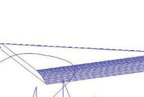
In order to create aircraft 3D surface, the body’s left and right parts are generated step by step with the help of Edge Mesh command. With the help of command Ruled Mesh the tail part and engines nozzles are created. The result of generation in three orthogonal and isometric projections is presented in Fig. 1.16. If necessary the body’s original plane figures can be corrected for aircraft aerodynamic characteristics.
Further, in order to create accurate rendering scene it is necessary to assign the materials and determine lighting. The work with materials consists of two stages: adding (creating) new materials to drawing and material binding to scene objects. Creation of appropriate materials is an important part of shading process because the final result considerably depends on this. The material, in its turn, interrelates with lighting; object color affects specular reflection. In AutoCAD graphic system there is a big choice of materials; they can be edited or new ones created [16].
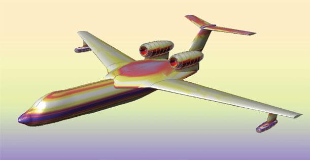
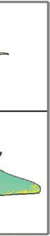
Notwithstanding that 3D models are more accurate than 2D ones they don’t look natural; they lack real colors, shadows, lighting. Shading enables us to generate an accurate image of a 3D scene based on different optical effects. In Fig. 1.17 rendering scenes of aircraft “Chiroptera,” shaded surfaces during cruising flight and target run are shown (Fig. 1.18). Design documentation can be also created in graphic system AutoCAD based on 3D model developed.
In conclusion it can be noted that in this paper the issues of new aircraft 3D modeling concept from creative sketches to accurate rendering were considered.
Fig. 1.16 3D surface model of aircraft in projections.
Fig. 1.17 Rendering of “Chiroptera” aircraft conceptual model (cruising model).
Fig. 1.18 Rendering of “Chiroptera” aircraft conceptual model (target run).
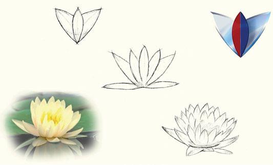
1.6 Conceptual Design of “Lotos” Motorcar
Today there are a lot of automotive giants in the world that produce new ranges of transportation with new technologies and possibilities each year. The companies embody the best solutions proposed by the designers. Design is the very beginning in the modern automotive industry. Each
part of the car – from symbol to steering wheel – is carefully designed in the creative hands of the designers. It is body concept that gives birth to internal characteristics of the vehicle. The vehicle’s outlook defines its “character”.
Among the existing works on conceptual design we would like to note the articles [19, 20]. These works examine the importance of the sketching stage in the process of conceptual design of vehicles. Article [21] is dedicated to motorcar conceptual design; the stages of sketching, threedimensional computer-aided modeling and final rendering of the scene are provided. The issues of initial stage of conceptual designing are described in detail in the book [22]. Provided there is the methodological basis of idea generation stage and determination of initial requirements for future structure.
This work is dedicated to three-dimensional computer-aided modeling of new vehicle concept. It should be noted that the issues of computer-aided modeling of airborne transportation means were reviewed by the authors in the works [15, 23]. The work [23] proposes conceptual visual-graphical solutions of new aircraft on the basis of bionic forms analysis.
The process of conceptual designing and modeling of transportation means takes several stages. At the first stage the sketch is created and a future model general view is drawn: composition solution; proportion of component parts relative to each other; main stylistic solutions. The concept of future prototype is chosen on the basis of analysis of natural forms visualization.
The concept of developed model design was determined by the lotus flower. Lotus (lat. nelumbo) refers to the kind of dicotyledonous plants, the only representative of the Nelumbonaceae family [24, 25]. Considering that the car design was inspired by this nice flower, the vehicle’s outlook reveals the bionic form of lotus petals. In the culture of many ancient civilizations lotus signified immortality and the Divine, regeneration and the Sun, exhaustless energy and spiritual power.
When we talk about the automotive industry, people have different associations; for some people cars are quick, for other people they are compact, and for yet others they are spacious. But the first and basic thing is the company and its mark that is directly associated with the car. If we think about such trademarks as Lamborghini and Ferrari, we imagine their symbols at once in the form of a bull for the first and a horse for the second, and both animals are depicted in rather dynamic aspects. The success of many companies depends much upon the good quality design that predetermines the success due to recognition. Fig. 1.19 provides the
Fig. 1.19 Creative quest.
sketches of initial bionic forms and variants of creative quest of graphical symbol.
Many modern car makers have series with special characteristics. We are interested in series of fast high-performance cars that are powerful and graceful, such as: Maserati Quattroporte, Audi A7, BMW 5-series, Jaguar XF, Lexus LS [26]. These very models are close to “Lotos” model by ideology.
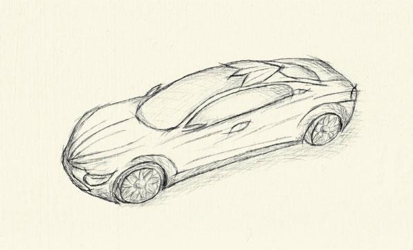
At the next stage the model is drawn with reference to man’s biometric parameters considering the requirements of ergonomics. Fig. 1.20 shows
Fig. 1.20 Final variant of vehicle sketsh.