
Instrumentation, 3 Volume Set Raghbir Singh Khandpur
Visit to download the full and correct content document: https://ebookmass.com/product/compendium-of-biomedical-instrumentation-3-volume -set-raghbir-singh-khandpur/

More products digital (pdf, epub, mobi) instant download maybe you interests ...

Ryan’s Retina: 3 Volume Set 6th Edition
https://ebookmass.com/product/ryans-retina-3-volume-set-6thedition/

Encyclopedia of Materials: Technical Ceramics and Glasses, 3-Volume Set Michael Pomeroy
https://ebookmass.com/product/encyclopedia-of-materialstechnical-ceramics-and-glasses-3-volume-set-michael-pomeroy/

Ryan’s Retina E Book: 3 Volume Set 6th Edition, (Ebook PDF)
https://ebookmass.com/product/ryans-retina-e-book-3-volumeset-6th-edition-ebook-pdf/

Encyclopedia of Biomedical Engineering (vol. 1-3) Min Wang
https://ebookmass.com/product/encyclopedia-of-biomedicalengineering-vol-1-3-min-wang/

Encyclopedia
of Mycology, Two Volume Set Óscar Zaragoza
https://ebookmass.com/product/encyclopedia-of-mycology-twovolume-set-oscar-zaragoza/

X-Ray Fluorescence in Biological Sciences: Principles, Instrumentation, and Applications Vivek K. Singh
https://ebookmass.com/product/x-ray-fluorescence-in-biologicalsciences-principles-instrumentation-and-applications-vivek-ksingh/

Men of the Misfit Inn: Volume 1 (Books 1-3): A Small Town Romance Boxed Set Kait Nolan
https://ebookmass.com/product/men-of-the-misfit-innvolume-1-books-1-3-a-small-town-romance-boxed-set-kait-nolan/

The Handbook of Applied Communication Research, 2 Volume Set O'Hair
https://ebookmass.com/product/the-handbook-of-appliedcommunication-research-2-volume-set-ohair/

Boys of Bridgewater Box Set (Books 1-3) Bella Michaels
https://ebookmass.com/product/boys-of-bridgewater-box-setbooks-1-3-bella-michaels/
Compendium of Biomedical Instrumentation
Compendium of Biomedical Instrumentation
Volume 1
Raghbir Singh Khandpur
Former Head, Medical Instruments Division
CSIR‐Central Scientific Instruments Organization Chandigarh, India
Founder Director, Centre for Electronics Design and Technology (Now Centre for Development of Advanced Computing) Mohali, India
Former Director General, Centre for Electronics Design and Technology of India Ministry of Electronics & Information Technology Govt. of India, New Delhi, India
Compendium of Biomedical Instrumentation
Volume 2
Raghbir Singh Khandpur
Former Head, Medical Instruments Division
CSIR‐Central Scientific Instruments Organization Chandigarh, India
Founder Director, Centre for Electronics Design and Technology (Now Centre for Development of Advanced Computing) Mohali, India
Former Director General, Centre for Electronics Design and Technology of India Ministry of Electronics & Information Technology Govt. of India, New Delhi, India
Compendium of Biomedical Instrumentation
Volume 3
Raghbir Singh Khandpur
Former Head, Medical Instruments Division
CSIR‐Central Scientific Instruments Organization Chandigarh, India
Founder Director, Centre for Electronics Design and Technology (Now Centre for Development of Advanced Computing) Mohali, India
Former Director General, Centre for Electronics Design and Technology of India Ministry of Electronics & Information Technology Govt. of India, New Delhi, India
This edition first published 2020 © 2020 John Wiley & Sons Ltd
All rights reserved. No part of this publication may be reproduced, stored in a retrieval system, or transmitted, in any form or by any means, electronic, mechanical, photocopying, recording or otherwise, except as permitted by law. Advice on how to obtain permission to reuse material from this title is available at http://www.wiley.com/go/permissions.
The right of Raghbir Singh Khandpur to be identified as the author of this work has been asserted in accordance with law.
Registered Offices
John Wiley & Sons, Inc., 111 River Street, Hoboken, NJ 07030, USA
John Wiley & Sons Ltd, The Atrium, Southern Gate, Chichester, West Sussex, PO19 8SQ, UK
Editorial Office
The Atrium, Southern Gate, Chichester, West Sussex, PO19 8SQ, UK
For details of our global editorial offices, customer services, and more information about Wiley products visit us at www.wiley.com.
Wiley also publishes its books in a variety of electronic formats and by print‐on‐demand. Some content that appears in standard print versions of this book may not be available in other formats.
Limit of Liability/Disclaimer of Warranty
In view of ongoing research, equipment modifications, changes in governmental regulations, and the constant flow of information relating to the use of experimental reagents, equipment, and devices, the reader is urged to review and evaluate the information provided in the package insert or instructions for each chemical, piece of equipment, reagent, or device for, among other things, any changes in the instructions or indication of usage and for added warnings and precautions. While the publisher and authors have used their best efforts in preparing this work, they make no representations or warranties with respect to the accuracy or completeness of the contents of this work and specifically disclaim all warranties; including without limitation any implied warranties of merchantability or fitness for a particular purpose. No warranty may be created or extended by sales representatives, written sales materials or promotional statements for this work. The fact that an organization, website, or product is referred to in this work as a citation and/or potential source of further information does not mean that the publisher and authors endorse the information or services the organization, website, or product may provide or recommendations it may make. This work is sold with the understanding that the publisher is not engaged in rendering professional services. The advice and strategies contained herein may not be suitable for your situation. You should consult with a specialist where appropriate. Further, readers should be aware that websites listed in this work may have changed or disappeared between when this work was written and when it is read. Neither the publisher nor authors shall be liable for any loss of profit or any other commercial damages, including but not limited to special, incidental, consequential, or other damages.
Library of Congress Cataloging‐in‐Publication Data Applied for
HB ISBN: 9781119288121
Cover Design: Wiley
Cover Image: © Martin Barraud/Getty Images
Set in 10/12pt WarnockPro by SPi Global, Chennai, India
Printed and bound by CPI Group (UK) Ltd, Croydon, CR0 4YY
237
238
239
244
246
247
248
249
Preface
Biomedical instruments and devices today occupy an important place in the delivery of healthcare at all levels of medical facilities from primary healthcare to tertiary‐level facilities. The range of these instruments and devices is spectacular and variety baffling. It is difficult to imagine a medical speciality where some kind of instruments are not required and used. They are employed for clinical diagnosis through measurement of physical parameters, laboratory analytical techniques, and various imaging modalities. On the other hand, therapeutic devices have altered the way the diseases are treated. Advanced research in the unknown realms of functioning of various physiological phenomena of living beings is becoming possible with MEMS and computer‐based instruments. The availability of a bewildering array of such instrumental techniques in clinical practice and a large variety of commercially available equipment have presented a great challenge before all those who are responsible for managing these technologies by way of their usage, operation, and maintenance and those engaged in advancing measurement techniques through research and development. The book is designed mainly for the active workers involved in hands‐on functions rather than peers in their respective fields.
The publication is a compilation of 400 instruments and devices arranged alphabetically. Effort has been made to cover almost the entire range of important and most popular instruments used for diagnosis, imaging, analysis, and therapy. Each instrument description covers four aspects: (i) purpose of the instrument, (ii) principle of operation covering physics, engineering and electronics, and data processing, (iii) brief specifications, and (iv) major applications. No attempt has been made to include historical developments of a particular instrument or device, as most state‐of‐the‐art instruments have been given a place in the publication. However, some instruments based on older‐generation technologies have been included for legacy purposes as they are still in use in some medical facilities. It has also been tried to include generic specifications as much as possible.
The motivation of the work arose from interactions with various biomedical instrumentation engineers particularly those who join in healthcare facilities after receiving their undergraduate degrees and get involved in managing medical technology, including rendering of advice on procurement of new instruments and gadgets. It falls on them to first understand the working principle of the instrument proposed to be procured and also to have an appreciation of the salient specifications. The service engineers are expected to broadly know as to what the instrument contains inside and the clinical engineer can help the clinician to adopt better measurement techniques.
I would like to acknowledge with thanks the contribution of various persons and agencies who have helped me to complete the work. First of all , I wish to thank McGraw‐Hill Education (India) Private Limited, New Delhi, for their permission to use a few lines here and there from my two books published earlier by them, namely, Handbook of Biomedical Instrumentation and Handbook of Analytical Instruments. I have tried to include commercial instruments from almost all important players in the field. All of them have shown tremendous cooperation in supplying high resolution images of their instruments along with associated information. Most of them have authenticated the accuracy of the text material and made useful suggestions for the improvement of the text. While it is not possible to individually name and acknowledge their contribution here, the assistance of each one of them has been acknowledged along with the respective instrument image under different chapters.
I am thankful to my wife Ramesh Khandpur who has always been a source of encouragement and strength in supporting my writing endeavours. I am sure my children Vimal, Gurdial, and Popila and grandchildren Ravleen, Harsheen, Manmeet, Ashna, and Gurtej will feel elated when they see this publication. Thanks are due to Gurdial and Sumit Khandpur for their timely help in preparing the response to the initial copyediting work. The interest shown by Balwinder and Jaswinder in the project is gratefully acknowledged.
I would also like to place on record my deep appreciation of M/s John Wiley & Sons, UK, particularly Mr Steven Fassioms, Mr Hari Sridharan, Ms Hannah Lee, and Ms Anita Yadav of the Delhi office for their constant support during the preparation and production of this book.
Dr R S Khandpur
Accelerometer
Purpose
Accelerometers are widely used as sensors for wearable medical devices to measure and assess physical activity (PA) in clinical/laboratory settings or free‐living environments. They are, however, mostly employed for ambulatory monitoring for continuously measuring long‐term activities of subjects in a free‐living environment. From the recorded activity data, it is possible to identify daily movements that are associated with an individual’s functional status and also to detect adverse activity, such as falls, through signal analysis and appropriate algorithm. In addition, energy expenditure is the most commonly found application of the accelerometers.
Principle
Any bodily movement produced by skeletal muscles that results in an energy expenditure can be regarded as PA. Various techniques and devices have been used to measure physical activities that employ wearable or body‐fixed motion sensors. These include gadgets ranging from simple switches, pedometers, goniometers, actometers, accelerometers, and gyroscopes. The measurement of physical activity employing accelerometers is the most preferred technique because the acceleration is proportional to external force and, as a consequence, can reflect intensity and frequency of human movement. Also, it is easy to obtain velocity and displacement information by integrating accelerometer data with respect to time. The accelerometers are also designed to respond to gravity, thereby providing tilt sensing with respect to reference planes when accelerometers rotate with objects on which they are mounted. The resulting inclination data from accelerometers help to classify body postures or orientations, thus providing sufficient information for measuring physical activity and a range of human routine activities.
Accelerometers are sensors that are designed to measure the acceleration of an object in motion along reference axes. These sensors are basically force sensors that sense linear acceleration along one or several directions, or angular motion about one or several axes. The former is called an accelerometer, while the latter is referred to as gyroscope. The principle on which an accelerometer operates is based on a mechanical sensing element that consists of a proof mass or seismic mass attached to a mechanical
suspension system with respect to a reference frame. Inertial force due to acceleration or gravity causes deflection of the proof mass according to Newton’s second law. The acceleration is measured electrically based on the physical changes in displacement of the proof mass with respect to the reference frame. The most common type of sensors used to measure acceleration are based on the principle of piezoresistivity, piezoelectricity, or differential capacitive measurement.
Piezoresistive Accelerometers
Piezoresistive accelerometers, also termed as strain gauge accelerometers, operate by measuring the change in electrical resistance of a piezoresistive element when mechanical stress is applied to it. Figure 1.1 shows the principle of piezoresistive accelerometer. The sensing element consists of a cantilever beam and its proof mass is determined by bulk micromachining. The acceleration causes the motion of the proof mass that can be detected by piezoresistors in the cantilever beam and proof mass. The piezoresistors are placed as two arms of a Wheatstone bridge that produces a voltage proportional to the applied acceleration.
In practice, a piezoresistive accelerometer is structurally quite stable. This is because it is composed of a silicon chip formed by the semiconductor production technology. An electrical bridge is formed by piezoresistors representing a mass and a beam which are fabricated on a silicon chip. The electrical bridge so formed by such piezoresistive resistors generates electrical signals that are proportional to the applied acceleration. The piezoresistive accelerometers can measure constant acceleration with respect to gravity as they are responsive to DC voltage. The piezoresistive accelerometers are simple and low cost but have lower level of the output signals and suffer from the temperature‐sensitive drift. Though they have a limited high frequency response, they are preferred in high shock applications.
Piezoelectric Accelerometers
This type of sensor is based on the piezoelectric effect. When certain types of crystals are compressed by application of some force, charges of opposite polarity accumulate on opposite sides of the crystal. Figure 1.2 shows a simplified schematic of a piezoelectric accelerometer. The accelerometer uses an internal piezoelectric element that is coupled with a proof mass to form an accelerometer system. Here, the sensing element
Piezoresistor
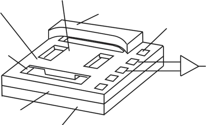
Figure 1.1 Principle of piezoresistive accelerometer.
Figure 1.2 Cross section of a piezoelectric accelerometer.
Seismic mass
Piezoelectric material
Solid base

Preload bolt
Acceleration
Output
Ampli er : need current excitation
bends due to applied acceleration, which causes a displacement of the proof mass, that results in an output voltage proportional to the applied acceleration. The accelerometer is a charge‐sensitive device in which an instantaneous change in stress on the piezoelectric element produces a voltage at the accelerometer’s output terminals that is proportional to the applied acceleration. Piezoelectric or charge mode accelerometers require an external amplifier or built‐in charge converter to amplify the generated charge, lower the output impedance for compatibility with measurement devices, and minimize susceptibility to external noise sources and crosstalk. These devices are usually integrated circuit piezoelectric (ICP) sensors.
A piezoelectric accelerometer’s sensitivity is specified in picocoulombs per gram (pC/g). Typical sensitivities are in the range of 0.5–1000 pC/g. Piezoelectric accelerometers only respond to AC phenomenon such as vibration or shock, rather than DC phenomenon such as the acceleration of gravity. The accelerometers can be applied to measure acceleration levels ranging from 4 g to greater than 100 g. The useful measurement range of a given system is often limited by its signal conditioning and measurement system.
Differential Capacitive Accelerometers
The displacement of the proof mass due to acceleration can also be identified by measuring changes in capacitance. Capacitive sensing accelerometers produce a voltage dependent on the distance between two planar surfaces or plates. One or both of these ‘plates’ are charged with an electrical current. When there is a change in the gap between the plates due to application of force, it changes the capacitance of the system, which can be easily measured in terms of voltage. There are several advantages of using capacitive accelerometers which include larger bandwidth, low power dissipation, faster response to motion, high accuracy and stability in operation. They are also less prone to noise and variation with temperature. Differential capacitive accelerometers are also responsive to static forces.
Figure 1.3 illustrates the working of the differential capacitive accelerometers. The sensing element of the accelerometer consists of two fixed plates attached to the substrate and a suspended plate. When the unit moves in the direction as shown in the diagram, the displacement of the suspended plate with respect to the two fixed plates changes, resulting in a change in capacitance of C1 and C2. An increase in C1 will result
Motion
Fixed plate 1
Fixed plate 2 C1 C2
Capacitance to voltage converter
Capacitance to voltage converter
Differential ampli er
Suspended plate
Figure 1.3 Principle of differential capacitance‐based accelerometer.
Gain/offset/ lter stage
0.5–4.5 V Output signal
Figure 1.4 Circuit diagram for signal conditioning of differential capacitance‐based accelerometer.
in a decrease in C2 and vice versa which can be sensed as a voltage signal. A simplified circuit diagram of the signal conditioner of the differential capacitance circuit is shown in Figure 1.4. The signal from the sensor is processed to obtain a filtered and amplified linear output. Due to the small capacitances involved and in order to reduce noise and thermal drift and increase the resolution, a differential capacitance system is employed.
Microelectromechanical Sensors (MEMS)-based Accelerometers
Most of the modern accelerometers are based on microelectromechanical sensors (MEMS). All the above‐mentioned technologies for converting acceleration to an electrical signal, namely, piezoelectric, piezoresistive, and capacitive change, can be used in the construction of MEMS‐based sensors. However, the preferred technology is capacitive sensing MEMS as it offers long‐term stability with high sensitivity. For this reason, capacitance‐based MEMS are used in some of the most demanding applications. These sensors are available in one‐, two‐, or three‐axis versions. Multiple axis measurements can also be grouped into a single monitor, allowing capturing of movement in multiple planes. Figure 1.5 shows the functions of an MEMS inertial sensors to detect and measure tilt, shock, rotation, vibration, or any other types of motion.
MEMS are silicon‐based micromachined sensors, which have on‐chip integration for measurements such as acceleration and vibration. The chip includes the sensor and the signal conditioning circuitry and consequently require only a few external components. Some chips also have built‐in analog‐to‐digital converter to convert the analog output of the signal conditioner to a digital format facilitating direct display on an LCD. They include adequate memory to record physical activity over 21‐day periods.

The MEMS chip comprises springs, masses, and motion‐sensing components. These sensors are fabricated using the standard IC processing technology commonly employed in wafer fabrication facilities. The sensor with a 3D structure, which allows free movement in all directions, is designed by using layers of oxide and polysilicon, IC photolithography, and selective etching techniques. The sensor is of differential capacitor type in which the plates on the wafer can be driven 180° out of phase. Any movement of the mass on application of force unbalances the capacitor and results in a square wave output whose amplitude is proportional to the acceleration.
Figure 1.6 shows the layout of various components of MEMS capacitance change‐based accelerometer on the chip. The digital accelerometers give output in the form of a variable frequency square wave, the method being known as pulse‐width modulation (PWM). A pulse width‐modulated accelerometer takes readings at a fixed rate, typically, say, at 1000 Hz. The value of the acceleration is proportional to the pulse width or duty cycle of the PWM signal. A demodulator in each axis rectifies the signal and determines the direction of acceleration. This output is given to a modulator that filters the analog signal and converts it to a duty cycle output. A microcontroller can be used to measure acceleration by timing both the duty cycle and the period of each axis. The duty cycle output would be 50% at a 0 g acceleration. A typical commercial MEMS‐based accelerometer chip is available from M/s Safron Collibrys, Switzerland, which is shown in Figure 1.7.
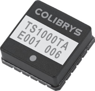
Figure 1.7 Typical MEMS‐based accelerometer chip. Acceleration
Figure 1.5 Various functions of an MEMS‐based sensor.
Torsion bar
Moving capacitor plate
Fixed capacitor plate
Suppor t
Substrate
Figure 1.6 Layout of various components on an MEMS capacitance change‐based accelerometer.
Ampli e r Analog-t o-digital con ve rt er
Displa y X -axis transducer Y -axis transducer Z -axis transducer
Curr ent-t ov oltage con ve rt er
Multiple xe r
C ontr ol logic
Figure 1.8 Block diagram of a three‐axis accelerometer circuit including in‐built A/D converter of MMA7660FC integrated chip from M/s Freescale.
Three‐axis accelerometers can detect motion in three different directions. A three‐axis accelerometer MMA7660FC as an integrated chip is available from M/s Freescale. The circuit diagram is shown in Figure 1.8. Although it basically targets handset applications, it can also be used in biomedical applications. It incorporates a range of user‐p3‐axis accelerometer programmable interrupts and sample rates. The chip is packaged in a small footprint (3 mm × 3 mm × 0.9 mm) DFN package. It communicates 6‐bit X‐, Y‐, and Z‐axis information with the processor, eliminating the need for an external A/D converter. The device draws only as little as 47 μA in active mode and 2 μA in standby mode.
The accelerometers have been found to be useful for measuring activities such as walking and running, but they do not accurately estimate others such as stationary biking and elliptical trainer. Accelerometers also have limitations in capturing upper extremity movement of the body and related activities. Many accelerometers can separate human movement from movement outside of the human range such as mechanical vibration, which may result from riding in a car, and similar sources of movement.
Accelerometers or devices based on them can be easily attached to a belt, which can be worn around the waist of the user. Some are also suitable to be wrapped around the wrists, thigh, or ankles. Ankle‐worn accelerometers can significantly reflect gait‐related features during locomotion or walking. In addition, steps, travel distance, velocity, and energy expenditure information can be measured using an ankle‐worn accelerometer.
Important Features of Accelerometers
A typical accelerometer is characterized by several features that include bandwidth, number of axes, and output range.
Bandwidth: The bandwidth of an accelerometer is usually expressed in hertz. The human body can create motion only up to the range of 10–12 Hz. For this reason, a bandwidth of 40–60 Hz is considered adequate for sensing tilt or human motion in an accelerometer.
Number of axes: Accelerometers can measure in one, two, or three dimensions. Although the most familiar type of accelerometers measure across two axes, the three‐axis accelerometers are also becoming increasingly common. Output range: To measure the acceleration of gravity for use as a tilt sensor, an output range of ±1.5 g is sufficient. For use as an impact sensor, which is one of the most common applications, ±5 g or more is desirable.
Specifications
Sensor type: MEMS
Range: ±8 g or ±16 g
Resolution: 12 bit (3.9 mg resolution)
Logging frequencies: 10–100 Hz
Memory: 0.5 Gb nonvolatile
Period of recording: 12 hours
Accelerometers are finding increasing application mostly related to fitness and sports activities. Besides the usual applications involving walking and running, accelerometer‐based step counters are promoted to encourage people to walk a few thousand steps each day. Accordingly, renowned shoe manufacturing companies are manufacturing and marketing sports watches for runners that include footpods, containing accelerometers to help determine the speed and distance for the runner wearing the unit. Accelerometers have also been employed to calculate gait parameters, such as stance and swing phase.
2
Air Bubble Detector
Purpose
Air bubble detectors, also called as bubble sensors or air‐in‐line sensors, are used with patient‐connected medical devices to monitor presence of air bubbles in dialysis machines, infusion pumps, transfusion lines, and blood processing systems and thus play a critical safety role in such devices.
Principle
Bubble detection is critical to maintain the steady fluid flowing circuit and prevent complications from air embolism. Air bubbles usually originate within the extracorporeal tubing and are carried with the solution flowing into the bloodstream. Such a situation may be present in haemodialysis while priming and preparing the lines for use. Air bubbles may also be formed as a result of turbulent flow of the fluids in the tubing and the vascular access. There is a likelihood of pulmonary microembolization taking place due to these air bubbles during haemodialysis. Thus, while dealing with medical fluid delivery services, it is important to ensure safety of the patient by accurately and reliably detecting small air bubbles flowing through fluid‐carrying tubing to prevent air embolism in arteries and veins during medical procedures. Otherwise, treatments requiring fluid delivery can put the patient at risk. Air bubble detectors are usually supplied as original equipment manufacturer (OEM) items so that they may be incorporated in the main equipment such as dialysis machine by their manufacturers. One such sensor is shown in Figure 2.1. The sensors/detectors are usually attached at the designated point of detection to the rigid or flexible plastic tubing of varying diameters. Various techniques that are used to detect air bubbles in flowing fluids are as follows:
Photoelectric method: Different physical principles are employed in air bubbles detection. The simplest method of air bubble detection involves use of a light source and a photodetector mounted opposite to each other across a tube carrying the fluid or blood. The presence of air bubble triggers a signal due to interruption of light if an air bubble is present in the fluid line. These devices were found to be insensitive to fibrin deposits on the inner wall of the bubble trap obstructing the light path. Also, the