[FREE PDF sample] Electrocardiography in ischemic heart disease clinical and imaging correlations an
Electrocardiography in ischemic heart disease clinical and imaging correlations and prognostic implications Second Edition Bayés De Luna
Visit to download the full and correct content document: https://ebookmass.com/product/electrocardiography-in-ischemic-heart-disease-clinica l-and-imaging-correlations-and-prognostic-implications-second-edition-bayes-de-luna/
More products digital (pdf, epub, mobi) instant download maybe you interests ...
Clinical and Imaging Correlations and Prognostic Implications
Second Edition
Miguel Fiol‐Sala, MD, PhD
Scientific Director of the Balearic Islands Institute of Health Research at the Hospital Son Espases, Palma, Balearic Islands, Spain
Yochai Birnbaum, MD, FACC, FAHA
Professor of Medicine-Cardiology and John S. Dunn Chair in Cardiology Research and Education at the Baylor College of Medicine Houston, TX, USA
Kjell Nikus, MD, PhD
Professor of Cardiology Faculty of Medicine and Health Technology Tampere University and Head of Department Heart Center, Tampere University Hospital Tampere, Finland
Antoni Bayés de Luna, MD, FESC, FACC
Director of Cardiology at Hospital Quirón and Emeritus Professor of Cardiology at Universitat Autònoma de Barcelona Barcelona, Spain
All rights reserved. No part of this publication may be reproduced, stored in a retrieval system, or transmitted, in any form or by any means, electronic, mechanical, photocopying, recording or otherwise, except as permitted by law. Advice on how to obtain permission to reuse material from this title is available at http://www.wiley.com/go/permissions.
The rights of Miguel Fiol‐Sala, Yochai Birnbaum, Kjell Nikus, and Antoni Bayés de Luna to be identified as the authors of the Editorial material in this work has been asserted in accordance with law.
Registered Office(s)
John Wiley & Sons, Inc., 111 River Street, Hoboken, NJ 07030, USA
John Wiley & Sons Ltd, The Atrium, Southern Gate, Chichester, West Sussex, PO19 8SQ, UK
Editorial Office
9600 Garsington Road, Oxford, OX4 2DQ, UK
For details of our global editorial offices, customer services, and more information about Wiley products visit us at www.wiley.com.
Wiley also publishes its books in a variety of electronic formats and by print‐on‐demand. Some content that appears in standard print versions of this book may not be available in other formats.
Limit of Liability/Disclaimer of Warranty
The contents of this work are intended to further general scientific research, understanding, and discussion only and are not intended and should not be relied upon as recommending or promoting scientific method, diagnosis, or treatment by physicians for any particular patient. In view of ongoing research, equipment modifications, changes in governmental regulations, and the constant flow of information relating to the use of medicines, equipment, and devices, the reader is urged to review and evaluate the information provided in the package insert or instructions for each medicine, equipment, or device for, among other things, any changes in the instructions or indication of usage and for added warnings and precautions. While the publisher and authors have used their best efforts in preparing this work, they make no representations or warranties with respect to the accuracy or completeness of the contents of this work and specifically disclaim all warranties, including without limitation any implied warranties of merchantability or fitness for a particular purpose. No warranty may be created or extended by sales representatives, written sales materials or promotional statements for this work. The fact that an organization, website, or product is referred to in this work as a citation and/or potential source of further information does not mean that the publisher and authors endorse the information or services the organization, website, or product may provide or recommendations it may make. This work is sold with the understanding that the publisher is not engaged in rendering professional services. The advice and strategies contained herein may not be suitable for your situation. You should consult with a specialist where appropriate. Further, readers should be aware that websites listed in this work may have changed or disappeared between when this work was written and when it is read. Neither the publisher nor authors shall be liable for any loss of profit or any other commercial damages, including but not limited to special, incidental, consequential, or other damages.
Library of Congress Cataloging‐in‐Publication Data
Title: Electrocardiography in ischemic heart disease : clinical and imaging correlations and prognostic implications / Miguel Fiol-Sala, Yochai Birnbaum, Kjell Nikus, Antoni Bayés de Luna.
Description: Second edition. | Hoboken, NJ : John Wiley & Sons, 2020. | Antoni Bayés de Luna’s name appears first in the previous edition. | Includes bibliographical references and index.
Identifiers: LCCN 2019024502 | ISBN 9781119422662 (cloth) | ISBN 9781119422297 (adobe pdf) | ISBN 9781119422280 (epub)
Set in 10/12pt Warnock by SPi Global, Pondicherry, India
Telemedicine in the Diagnosis of Ischemic Heart Disease Through the Surface Elec trocardiogram 355
References 369
Index 401 Color plate section can be found facing page 180
Foreword to the Second Edition
Interpretation of the ECG is an art which wrongly has received less attention in recent graduate and postgraduate teaching, whereas high-tech imaging techniques and specific biomarkers are increasingly popular. As highlighted by the authors in their introduction, the ability of the ECG to provide information on the function and the structure of the heart, as well as on the localization of processes, makes it a stillinvaluable tool. The ECG can also provide repeated and even continuous information about the course of a specific cardiac condition. In addition, it does not interfere with or alter the substrate that it assesses. In these ways, it represents an ideal method, especially when used to monitor the evolving process of acute or subacute ischemia. In certain instances, like those in which a coronary angiogram does not clearly indicate the culprit lesion, the ECG can be the most valuable and readily available tool for decision-making.
This compendium was first published in 2008 by Antoni Bayés de Luna and Miquel Fiol‐Sala. These two prominent and internationally renowned electrocardiography experts were determined to demonstrate the ECG’s significant role in diagnosing, monitoring, and managing the various manifestations of ischemic heart disease. Both are now complemented by another two internationally renowned scientists and clinicians: Yochai Birnbaum and Kjell Nikus. Together, these four authors have written the 15 chapters that comprise this book, while also
acknowledging the valued support of an array of experts and peers.
The unique character of this book is exemplified by the numerous correlations of the ECG to cardiac anatomy and function, based on a spectrum of cardiac imaging modalities like coronary angiography, echocardiography, radioisotope imaging, magnetic resonance imaging, and computer tomography. As in the first edition, the ECG changes in ischemia and their electrophysiologic basis have been systematically assessed and then specified in different clinical settings of ischemic heart disease, including their prognostic implications. All chapters have been updated and adapted to reflect the present nomenclature. Also, more recent, emerging topics, like the role of telemedicine in the diagnosis of ischemic heart disease, are dealt with.
In the foreword to the first edition, I wrote that this book has the potential to become the “bible” in its field. Indeed, the second edition will continue to serve as a valuable teaching source and as a standard reference tool.
This book can be highly recommended to all cardiologists and internists who care for the large number of patients with manifestations of ischemic heart disease.
May 2019
Günter Breithardt, EFESC, FACC, FEHRS Professor Emeritus of Medicine (Cardiology) Previous Head of the Department of Cardiology and Angiology, University Hospital of Münster, Münster, Germany
Foreword to the First Edition
The readily available and inexpensive nature of the electrocardiogram (ECG) makes it a particularly attractive diagnostic tool. One of the most important applications of the ECG is in the evaluation of patients with ischemic heart disease. This second edition of an elegant textbook offers a refreshing, modernistic look at the surface electrocardiogram by experts in the field. In a single volume, the reader finds a richly illustrated resource that integrates clinical findings, coronary angiography, contemporary imaging modalities, echocardiography (computed tomography, SPECT perfusion studies, cardiac magnetic resonance studies), and cutting-edge biomarker findings with a 100-year old diagnostic test – the 12-lead surface ECG. The book is again divided into two parts. First, electrocardiographic patterns of ischemia, injury, and infarction are discussed. Polar maps, vectorial illustrations, and simple diagrams illustrating the relationship between myocyte action potentials and the surface electrocardiogram are appealing for both the novice and experienced reader. The second part of the book explores the use of the surface electrocardiogram in a variety of clinical settings of ischemic heart disease, touching on the correlations with coronary anatomy and the prognostic implications that can be gleaned from the ECG.
The authors of the first edition, Drs. Bayés de Luna and Fiol-Sala added two internationally recognized experts, Drs. Birnbaum and Nikus, in the present edition. This collective group of innovative authors have kept pace
with the contemporary nomenclature in the acute coronary syndrome spectrum, evolving universal definitions of myocardial infarction and the alterations that occur when a patient transitions from the acute to the chronic phase of ischemic heart disease. A particularly attractive feature of this second edition is the incorporation of case studies − not only a useful resource for the individual practitioner, but an invaluable pedagogical resource as well.
This textbook is a marvelous example of what can be accomplished when clinicians who are comfortable at the patient’s bedside also have the visionary insight to incorporate new knowledge from contemporary cardiac imaging procedures into a fresh view of an older, but still extremely useful, diagnostic test. As with the classical 12-lead electrocardiogram itself, readers of this textbook will find themselves returning to it over and over again because of the depth and breadth of its clinical usefulness.
April 2019 Boston, USA
Elliott
M. Antman
Senior Investigator, TIMI Study Group Professor of Medicine, Harvard Medical School
Cardiovascular Division Brigham and Women’s Hospital Boston, MA USA
Introduction
The electrocardiogram (ECG), which was discovered more than 100 years ago, appears to be more alive than ever. The ECG is an important tool for identifying different ECG morphological abnormalities, including arrhythmias, conduction blocks at all levels, pre‐excitation, and acute and chronic changes of ischemia and infarction for which ECG has been the “gold‐standard” diagnostic technique. In addition, the ECG assists in detecting morphologic changes related to remodeling and hypertrophy.
The ECG undergoes continuous re‐evaluation in scientific publications, and it has proved its value as an important clinical tool in the diagnosis and risk stratification of various cardiac diseases. Every year there is more and more evidence to demonstrate that the ECG provides important clinical information, and its applications are growing and will be expanded in the future.
Although the usefulness of the surface ECG is important in all types of heart disease, it stands out particularly in the case of ischemic heart disease (IHD), for various reasons. The ECG is the key diagnostic tool both in the acute phase of IHD (acute coronary syndromes, ACS) and in the chronic one (Q‐wave infarction). Furthermore, it is crucial for risk stratification in patients with acute ischemic pain. Based on the ECG findings, critical therapeutic decisions are made about reperfusion therapy in ST‐elevation ACS (STE‐ACS). In the case of an ACS, especially in STE‐ACS, careful evaluation of ST‐segment deviations in different leads allows
us to predict not only the occluded artery but also the level of occlusion. Therefore, the ECG helps to stratify risk and, consequently, to take the most appropriate therapeutic decisions.
In the chronic phase of Q‐wave infarction, the ECG is also very useful, since the identification of different ECG patterns gives a reliable approximation of the infarcted area.
Lastly, the ECG is of great importance, as the number of patients with IHD is very large, and therefore the repercussion of proper decisions made based on the ECG changes in combination with the clinical situation may have an extraordinary social and economic impact.
In spite of all the above‐mentioned arguments, there are only a few books that have dealt in depth with the value of ECG in IHD. Over 40 years ago, Schamroth and Goldberger wrote two important works, dedicated more to the chronic phase of IHD, but the information provided therein has inevitably become outdated in many aspects. Years later, works done by two groups of investigators, those of Wellens and Sclarovsky, published pioneering studies on the importance of the ECG in the acute phase of IHD. We nevertheless considered that, in the overall context of the ECG´s importance in IHD, there remained a space to fill in the field. That is what we intend to do with this publication.
One of the most important and new aspects of the book is the great number of correlations, not only with coronary angiography, but also with echocardiography,
nuclear studies, and new imaging techniques, especially cardiovascular magnetic resonance (CMR) imaging and coronary multidetector computer tomography (CMDCT). All these correlations have given us a huge amount of important new information.
In the book, we also explain the ECG patterns of chronic Q‐wave myocardial infarction (MI) based on the correlation with the vectorcardiographic loops, although the use of this technique is time‐consuming and has not become popular in clinical practice.
When necessary, we also comment on the role of other non‐invasive electrocardiographic techniques, especially exercise ECG, Holter monitoring, and tele‐ECG. Invasive electrophysiological techniques do not have a central role in IHD, although they are necessary in some aspects of arrhythmic sequalae such as ablation procedures in ventricular arrhythmias.
This book consists of two parts. In the first one, following comments on the most important aspects of the anatomy of the heart related to IHD and based on coronary angiography and imaging correlations, we discuss ECG concepts and patterns of subendocardial and transmural ischemia and necrosis. We eliminated the term injury as we consider this term pathophysiologically irrelevant when dealing with the ECG in IHD. We discuss electrophysiological mechanisms behind the ECG presentations in different types of myocardial ischemia and describe the correlations between the ECG patterns in different leads and the myocardial area involved. Correlations between ECG curves and vectocardiographic loops constitute a key to understanding the ECG morphologies.
In the second part of the book, the ECG patterns are dealt with in different settings of IHD, including prognostic implications. The new chapters added compared with the first edition are: Differentiating ST‐elevation Myocardial Infarction from Non‐Ischemic ST elevation; common mistakes in the diagnosis of Acute Coronary syndromes; Telemedicine
in the diagnosis of Ischemic Heart Disease through the surface electrocardiogram.
This second edition of the book has incorporated the contributions of two established experts in the ECG of IHD: Yochai Birnbaum and Kjell Nikus. With their extensive experience, they have extended the clinical and practical levels of ECG information’s utilization in IHD patient treatment. This is important, because all information is presented in a homogeneous manner, without the contradictory opinions that often appear in “edited” books. The text has been excessively updated and 183 new bibliographical references have been added.
An important novelty of this second edition is the incorporation of four case reports for self‐assessment after each chapter, described in a practical sense. It is our wish that the case reports will be of help to the reader when facing ECG tracings of patients with a suspected IHD.
We want to express our gratitude to Elliott Antman, pioneer in many aspects of IHD, who again has written a generous foreword to this second edition of the book. Also, our thanks to Günter Breithardt, an expert and pioneer in electrocardiology, who also has written an outstanding foreword emphasizing the electrocardiographic aspects of the book. We also very much appreciate the advice and friendship of Hein J.J. Wellens, Wojciech Zareba, and Samuel Sclarovsky, with whom we have shared many aspects of the new ideas expressed in this book.
Finally, we would like to express our gratitude to Andres Carrillo, Alberto Rodriguez, and Maria Riera from the Intensive and Coronary Care Unit of Hospital Son Espases, Miquel B. Fiol, Jr. for his help in improving the quality of some figures, Ramón Rotger from the Radiology Department of Clinica Rotger, and Vicente Peral, Jaume Maristany, Mar Alameda, Marcos Pascual, and Alfredo Gómez from the Cath Lab of Hospital Son Espases.
Part I
The ECG Changes Secondary to Ischemic Heart Disease
Electrophysiologic Bases
1 Anatomy of the Heart
The Importance of Imaging Techniques Correlations
The surface electrocardiogram (ECG) in both the acute and chronic phase of ischemic heart disease (IHD) may give crucial information about the coronary artery involved and the area‐at‐risk for myocardial injury. Knowing the anatomy of the heart, especially the ventricular walls and coronary tree, helps to understand the various ECG patterns present in IHD. However, the electric activity of the heart is influenced by numerous cardiac and non‐cardiac factors. Structural (chamber size, hypertrophy, presence of diffuse fibrosis, or localized scar, presence of pericardial effusion, etc.), functional and metabolic (ischemia, post‐ischemic stage, inflammation) aspects and diseases of the conduction system (CS) can all modify the ECG. Non‐cardiac factors include the position of the heart in the chest (horizontal position in obese patients, vertical in patients with emphysema, altered anatomy after pulmonary surgery, atelectasis, or pneumothorax), the distance of the electrodes from the heart and the width of the chest wall (effusion, adipose tissue, radical mastectomy, etc.), electrolyte imbalance and drug effects. This information together with the ECG‐clinical correlation is very important for diagnosis and risk stratification, as will be demonstrated in this book.
For centuries, since the pioneering works of Vesalio, Leonardo da Vinci, Lower, and Bourgery‐Jacob, pathology has been a unique method to study the anatomy of the heart. Since the end of the nineteenth century, the visualization of the heart in vivo has been
possible by X‐ray examination. The last 40–50 years started the era of invasive imaging techniques with cardiac catheterization, including coronary angiography, and non‐invasive imaging techniques, first with echocardiography and later with radionuclide studies, computed tomography (CT) and cardiovascular magnetic resonance (CMR) imaging. These techniques have opened up new horizons to study, not only the anatomy of the heart, coronary arteries and great vessels, but also myocardial function, metabolism and perfusion, and the characterization of the valves, pericardium, etc.
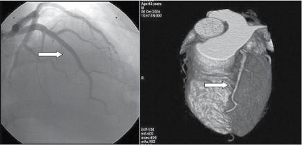
From an ECG standpoint, coronary angiography (Figure 1.1) is especially important in the acute phase for diagnosing the disease and correlating the site of occlusion with the ST‐segment deviations. It is also useful in the chronic phase of the disease. However, in the chronic phase of Q‐wave myocardial infarction (MI) the ECG does not usually predict the state of the coronary tree, because revascularization has often modified the characteristics of the occlusion responsible for the MI (Basso and Thiene 2006). Moreover, coronary angiography is insensitive for detecting minor collaterals that could attenuate ischemia. Coronary angiography does not give information about the myocardium and, thus, cannot directly assess the extent and severity of ischemia, especially in the acute phase of acute coronary syndromes (ACSs).
In patients with non‐ ST‐elevation ACS, the culprit lesion is not always identifiable
by angiography, especially in patients without active ischemia during the time of angiography or with multi‐vessel disease. Cine angiography of the left ventricle (LV) may give information for identifying hypokinetic or akinetic areas, but in practice, echocardiography is the preferred technique for this purpose. After the acute phase of myocardial ischemia, hypo‐/akinetic myocardial
segments usually corelate with the extent of tissue injury (Shen, Tribouilloy, and Lesbre 1991a,b; Takatsu et al. 1988; Takatsu, Osugui, and Nagaya 1986; Warner et al. 1986).
Computed coronary tomography angiography (CTA) is an alternative to invasive angiography to explore the coronary artery anatomy, especially in situations with low likelihood of need for percutaneous coronary
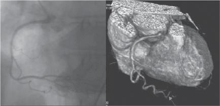
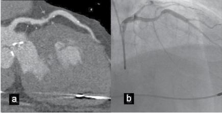
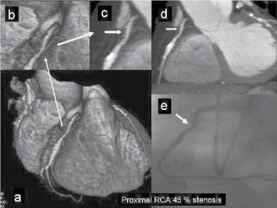
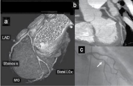
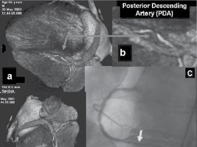
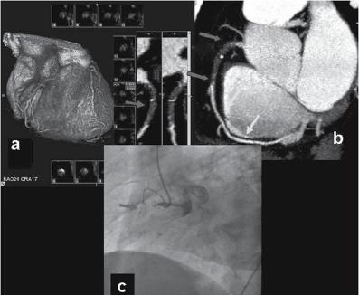
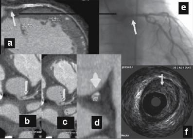
Figure 1.1 (A) Normal case: coronary angiography (left) and three‐dimensional CTA (right) showing normal left anterior descending (LAD, arrow) and left circumflex (LCX) coronary arteries. The latter is partially covered by the left appendix in CTA. (B) Normal case: coronary angiography (left) and CTA (right) showing a normal dominant right coronary artery (RCA). (C) An 85‐year‐old man with atypical chest pain: (a) Maximal intensity projection (MIP) of CTA with tight mid‐LAD stenosis that correlates perfectly with coronary angiography (b). (D) Similar case as (C) but with the stenosis in the proximal RCA. (a–d) CTA and (e) coronary angiography. (E) A patient with tight stenosis in the LCX before a bifurcation. (a) and (b) CTA and (c) coronary angiography. (F) These images show that CTA may also demonstrate the presence of stenosis in distal vessel branches, in this case in the posterior descending branch of the RCA. (a–b) CTA and (c) coronary angiography. (G) These images show that CTA (a, b) may delineate the length of a total occlusion and visualize the distal branches (see arrows in (b)). Collateral flow from the LAD to the RCA may be better visualized with CTA than with conventional coronary angiography (c: here only the RCA is shown). (H) A 42‐year‐old patient with a stent implanted in the LAD six months before. The patient complained of atypical chest pain and underwent CTA. The MIP images of CTA (a–c) show no significant restenosis, but some plaque formation in the left main trunk (d, circle) that was not well seen in coronary angiography (e). The degree of luminal obstruction by the plaque can be exactly measured by intravascular ultrasound (IVUS) (f). The ECG showed mildly inverted T waves in V1–V3 during follow‐up (see Plate 1 in color plates).
(a)
(b)
Figure 1.1 (Continued)
(d)
(e)
(f)
1.1 (Continued)
(h)
Figure
intervention (PCI) (Figure 1.1). CTA may provide additional diagnostic information for clinical decision‐making in contemporary stable chest pain patients with intermediate pre‐test probability for IHD (Hoffmann et al. 2017). In additional to narrowing, CTA can provide information on coronary distribution, including abnormalities in the origin and course of the arteries, and presence of coronary aneurysms. However, the accuracy of assessing the severity of coronary stenosis in highly calcified lesions and within stents is reduced.
The era of modern non‐invasive cardiac imaging started with echocardiography, which is very convenient for out‐patient and bedside evaluation. Echocardiography plays an important role, especially in the acute phase, for evaluation of LV function and mechanical complications of acute MI (Figures 1.2, 11.2, and 11.3). The method is also of clear value in chronic IHD patients for the study of LV function; both global and regional wall motion abnormalities can easily be detected (Bogaty et al. 2002; Matetzky et al. 1999; Mitamura et al. 1981). Both the non‐ST‐elevation acute coronary syndrome (NSTE‐ACS) and ST‐elevation MI (STE‐ACS) guidelines highlight the importance of transthoracic echocardiography in the diagnosis, differential diagnosis and risk stratification in ACS patients (Roffi et al. 2016; Steg et al. 2012). Visualization of a regional decrease in systolic movement of the inner layers of the LV and a decrease in myocardial thickening are the main criteria for the diagnosis of myocardial ischemia (Figure 1.2) (Leischik et al. 2016). Yet, echocardiography cannot always differentiate between an old infarction and acute ischemia. Echocardiography may aid in decision‐making in the emergency room when the ECG findings are inconclusive, since regional wall‐motion abnormalities occur within minutes following coronary occlusion, well before necrosis. However, lack of regional wall motion abnormalities cannot rule out acute ischemia, especially in patients with left ventricular hypertrophy (Neuman et al. 2004). Growing evidence of the use of tissue Doppler and strain imaging in acute myocardial ischemia is
emerging, but the methods are not yet ready for large‐scale routine use in the diagnostic workup of patients with suspicion of ACS (Smiseth et al. 2016). However, echocardiography tends to overestimate the area‐at‐risk, and thus its reliability is good but not excellent. Stress echocardiography and especially nuclear imaging (single‐photon emission computed tomography, SPECT) have been extensively used for the detection of perfusion abnormalities during a stress test. Also, nuclear imaging at rest has been used for detecting perfusion defects in patients presenting with ACS, especially for the estimation of the ischemic area‐at‐risk in patients with STE‐ACS (Leischik et al. 2016; Gallik et al. 1995; Huey et al. 1988; Zafrir et al. 2004) (Figure 1.3). These methods are useful in cases with dubious precordial pain with a positive exercise test without symptoms. However, in some cases (non‐transmural infarction) the extension of the infarction may be underestimated while in patients with left bundle branch block (LBBB), there may be false‐positive results. The most recent imaging techniques are CMR imaging (Figure 1.4) and the already mentioned CTA (Figure 1.1). CMR, which may also be used for perfusion and function studies of the myocardium, gives the best “in vivo” anatomic information about the heart. Thus, this technique, especially with gadolinium injection – contrast‐enhanced CMR (CE‐CMR) – is very useful for identifying and locating MIs, as well as for determining transmurality comparable to pathological studies (Bayés de Luna et al. 2006a; Cino et al. 2006; Moon et al. 2004; Salvanayegam et al. 2004; Wu et al. 2001). This is the reason that CE‐CMR has become the gold standard technique for studying correlations between ECG findings and infarcted myocardial areas in the chronic phase of coronary artery disease (CAD) (Bayés de Luna et al. 2006a; Cino et al. 2006; Engblom et al. 2002, 2003). Also according to the location of hyperenhancement areas in CE‐CMR, the technique can distinguish between ischemic and non‐ischemic etiologies (Figure 1.5). The sequence of evolving transmural MI can be studied (Mahrholdt et al. 2005a,b). In addition, CMR can reveal
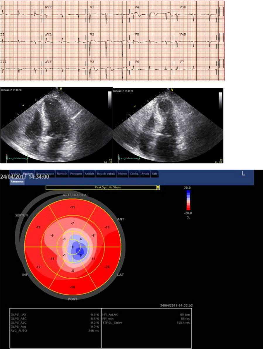
Figure 1.2 ECG‐echocardiography correlation. Post‐reperfusion ECG of an 82‐year‐old patient with LAD occlusion. The ECG shows anteroapical STE‐ACS. There is ST‐segment elevation in I and aVL: although the occlusion was in the mid‐LAD, there was one or more diagonal branches distal to the occlusion (Eskola et al. 2007) End‐diastolic (left) and end‐systolic (right) apical long‐axis views show hypokinesia of the apex and compensatory hyperkinesia of the basal septum and lateral wall. Strain rate imaging (bull’s eye) clearly delineates the region with apical dyskinesia (see Plate 2 in color plates).
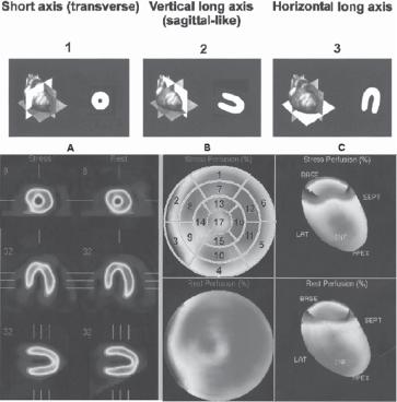
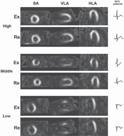
Figure 1.3 Examples of exercise test – nuclear imaging (SPECT) correlation. (a) Above: Observe the three heart planes with their transections (see Figure 1.4b) used by nuclear medicine experts (and other imaging techniques) to transect the heart: (1) short‐axis (transverse) view (SA), (2) vertical long‐axis view (VLA) (oblique sagittal‐like), and (3) horizontal long‐axis (HLA) view. The short‐axis transections are at the mid‐apical level (see Figure 1.8). The segmentation of the heart used in this book is shown (Cerqueira, Weissman, and Disizian 2002). In the middle is also a bull’s eye image presented. This patient has normal left ventricular perfusion. (B) Above: In the three planes (SA, VLA, and HLA): (A) normal uptake at rest (Re) and during exercise (Ex) can be observed. Middle: Abnormal uptake only during exercise of segments 7, 13, and 17 (see Figure 1.8) in a patient with ischemia produced by distal involvement of a non‐wrapping LAD. The basal part of the anterior wall of the LV is not involved. Below: abnormal uptake during rest and exercise in a patient in the chronic post‐MI phase caused by distal occlusion of very long LAD that wraps the apex involving part of the inferior wall (segments 7, 13, and 17 and also 15) (see Figure 1.8). In this case abnormal uptake is also evident in the rest image (see plate 3 in color plates).
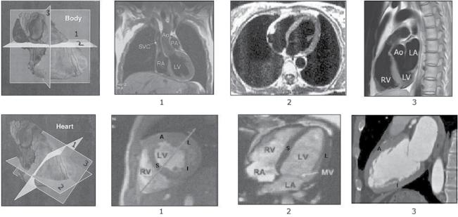
Figure 1.4 CMR imaging. (a) Transections of the heart following the classical human body planes: (1) frontal plane, (2) horizontal plane, and (3) sagittal plane. (b) Transections of the heart following the heart planes that cut the body obliquely. These are the planes used by the cardiac imaging experts: (1) short‐axis (transverse) view, in this case at mid‐level (see b (1)); (2) horizontal long‐axis view; (3) vertical long‐axis view (oblique sagittal‐like). Check the great difference between the sagittal plane according to human body planes (a (3)) and the heart planes (b (3)). (b) shows the four walls of the heart with the classical names: septal (S), anterior (A), lateral (L) and inferoposterior. Currently, the inferoposterior wall is for consistency named inferior (I) (see Figure 1.8).
inflammatory processes (Saeed et al. 2017). Apart from being the most accurate modality for the assessment of old infarct scars, cardiac CMR has a central role in the setting of STE‐ACS. T2‐weighted imaging can depict zones with edema 2–7 days after reperfusion. Edema is considered as the equivalent of the ischemic area‐at‐risk in acute total coronary occlusion. Thus, CMR is the first imaging technique to show the ischemic area‐at‐risk even after reperfusion has occurred (Mangion 2016). Thus, for the first time we can correlate ECG changes during the acute phase of STE‐ACS with the extent and location, and maybe even the severity, of myocardial ischemia. Nevertheless, there is no published data to correlate ECG and CMR findings from the acute phase of STE‐ACS in large patient populations and with different locations of culprit lesions. When assessing CMR findings in CAD, one has to take into consideration the variability in coronary artery anatomy (Rinta‐Kiikka et al. 2014). CMR can demonstrate post‐reperfusion microvascular
obstruction (no‐reflow) and myocardial hemorrhage and using late gadolinium sequences for assessing the extent of infarction and the edema score for the size of the area at risk, salvage index can be reliably assessed (Mangion et al. 2016). The reproducibility of CE‐CMR with time, especially after the acute phase, is very good. It also has the advantage of not producing radiation. The current limitation of CMR, which will probably be solved in the next few years, is the detailed study of the coronary tree. Currently, this may be performed non‐invasively by CTA (see above Figure 1.1).
1.1 The walls of the Heart and their Segmentation as Assessed by CMR (Figures 1.4–1.13)
In the past, different imaging modalities used different terms to describe the various segments of the LV (see Figures 1.4–1.13).
Figure 1.5 CMR hyperenhancement patterns found in clinical practice. If hyperenhancement is present, the subendocardium should be involved in patients with ischemic disease. Isolated mid‐wall or subepicardial hyperenhancement strongly suggests a “non‐ischemic” etiology. Source: From Marhrholdt 2005a.
It led to confusion when the different modalities were compared. The heart is located in the central‐left part of the thorax (lying on the diaphragm) and is oriented anteriorly, with the apex directed forwards (Figure 1.4).
The LV is cone shaped. Although its borders are imprecise, classically (Myers et al.
A. Subendocardial infarct
B. Transmular infarct
A. Mid-wall HE
B. Epicardial HE
1948a,b; Myers, Howard, and Stofer 1948c), it has been divided, except in its most inferior part of the apex, into four walls, till very recently named septal, anterior, lateral, and inferoposterior. In the 1940s–1950s the inferoposterior wall was named just posterior (by Goldberger) (Figure 1.6a), probably because it was considered opposed to the anterior wall. Later on (Perloff 1964), only the basal part of this wall, which was thought to bend upwards, was considered to be the posterior wall (Figure 1.6b). Therefore, it was named “true posterior” and the rest of the wall as “inferior” (Figure 1.6). According to that, for more than 40 years the terms “true” or “strict posterior infarction,” “‐injury” and “‐ischemia” have been applied, when it was considered that the basal part of the inferoposterior wall was affected. The committee of the experts of the International Society of Computerized ECG (Macfarlane and Veitch Lawrie 1989), in accordance with the publications of Selvester and Wagner, named these walls anterosuperior, anterolateral, posterolateral, and inferior, respectively. However, this nomenclature has
not been popularized, and the classical names (Figure 1.7a) are still mostly used in the majority of papers (Roberts and Gardin 1978), ECG books (Figure 1.7b–d), task forces (Surawicz et al. 1978) and statements (Hazinsky, Cummis, and Field 2000).
Later on, in the era of imaging techniques, the heart was transected into different planes (Figure 1.7) and different names were given to the walls of the heart by echocardiographers and experts in nuclear medicine. However, the consensus of the North American Societies for Imaging (Cerqueira, Weissman, and Disizian 2002) divided the LV into 17 segments and 4 walls: septal, anterior, lateral, and inferior (Figures 1.8 and 1.9). Therefore, the word “posterior” has to be omitted. Figures 1.8 and 1.9 show the 17 segments into which the four LV walls are divided (6 basal, 6 medial, 4 inferior, and the apex), and the right side of Figure 1.9 shows the walls of the heart with their corresponding segments on a polar “bull’s eye” map, as used by specialists in nuclear medicine. In the rest of the book we will use this current terminology.
Figure 1.6 Above: The concept of anterior and posterior infarction according to Goldberger. Below: The concept of anterior and true or strict posterior infarction according to Perloff (1964). The other part of the wall that lies on the diaphragm was later named inferior.
Perfoll, 1964
Figure 1.7 (a) The left ventricle may be divided into four walls that till very recently were usually named anterior (a), inferoposterior (IP) or diaphragmatic, septal (S) and lateral (L). However, according to the arguments given in this book, we consider that the “inferoposterior” wall has to be named just “inferior.” (b–d) Different drawings of the inferoposterior wall (inferior + posterior walls) according to different ECG textbooks (see inside the figure). In all of them the posterior wall corresponds to the basal part of the wall lying on the diaphragm that was thought to bend upwards. It was considered that the heart was located strictly in an anteroposterior position in the thorax (Figures 1.11a). CMR gives us the information that the inferoposterior wall lies flat, even in its basal part, in around two‐third of cases (Figure 1.12), which means that the heart is always located in an oblique position (Figure 1.11b,c).
Source: Kennedy R.J. Varrialle P, Alferito JC. Textbook of vectocardiography. Harper and Row. N.J. 1970
Figure 1.8 (a) Segments into which the heart is divided, according to the transverse (short‐axis view) transections performed at the basal, mid, and apical levels. The basal and medial transections delineate six segments each, while the apical transection shows four segments. Together with the apex, they constitute the 17 segments in which the heart can be divided according to the classification performed by the American imaging societies (Cerqueira, Weissman, and Disizian 2002). (b) View of the 17 segments with the heart open in a horizontal long‐axis view, and (c) vertical long‐axis (sagittal‐like) view seen from the right side. Figure 1.13 shows the perfusion of these segments by the corresponding coronary arteries.
(A)
Inferior (I)
Inferior wall
Figure 1.9 Images of the segments into which the left ventricle is divided according to the transverse transections (short‐axis view) performed at the basal, mid, and apical levels, considering that the heart is located in the thorax in a posteroanterior and right‐to‐left position. Segment 4, inferobasal, was classically named posterior wall. The basal and medial transections delineate six segments each, while the apical transection shows four segments. Together with the apex, the left ventricle can be divided into 17 segments. Note, in the mid‐transection, the location of the papillary muscles is shown. To the right, all 17 segments in the form of a polar map (bull’s eye), just as it is represented in nuclear medicine reports.
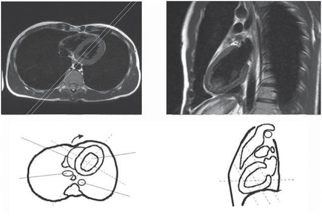
Thanks to CMR correlations (Figure 1.10), there is evidence that the sagittal view of the heart is, in respect to the thorax, located with an oblique right‐to‐left inclination rather than in a strictly anteroposterior position. This helps us to understand how the RS (R) or predominant ST‐segment depression patterns in V1 is the consequence of infarction of the lateral, not the inferobasal, segment (classical posterior wall) (Figure 1.11). However, it must be kept in mind that in the majority of individuals, except for the very lean ones (see Figure 1.12c), the part of the basal inferior wall, that can be really posterior, depolarizes late and therefore, cannot generate Q waves when infarcted (segment 4, or inferobasal).
The usefulness of invasive and non‐invasive imaging techniques and their correlations with ECG in IHD:
● Non‐invasive imaging techniques, especially SPECT, are very useful in detecting perfusion defects during the exercise test.
● In this book, we will point out the importance of ECG‐coronary angiography correlations to identify the coronary artery occlusion site and the myocardial area‐at‐risk.
● The role of coronary angiography, and especially in chronic IHD of CTA, will be discussed.
● In chronic MI we will emphasize the importance of the ECG‐CMR correlations to identify and locate the area of infarction.
● ECG is very useful in the coronary care unit (CCU) and is also used routinely in the chronic phase.
● X‐ray examination still plays a role, especially in the acute phase (cardiac enlargement and pulmonary edema), and in the detection of aneurysms and calcifications, visualization of pacemaker leads, etc.
In order to clarify the terminology of the walls of the heart, a committee appointed by ISHNE (the International Society for Holter and Non‐invasive Electrocardiography) made the following recommendations (Bayés de Luna 2006c):
1) Historically, the terms “true” or “strictly posterior” MI have been applied when the basal part of the LV wall that lies on the diaphragm was involved. In echocardiography the term “posterior” was replaced by “inferolateral”, some noninvasive imaging reports still use the term “posterior” or “posterolateral”. It is the consensus of this report to abandon the term “posterior” and to recommend that the term “inferior” be applied to the entire LV wall that lies on the diaphragm.
Figure 1.10 CMR imaging. (a) Thoracic horizontal axial plane at the level of the “xy” line of the drawing on the right side of the figure. The four walls can be adequately observed: anterior (A), septal (S), lateral (L), and inferior (I), represented by the inferobasal portion of the wall (segment 4 of the Cerqueira et al. statement) that bends upwards in this case (b). The infarction vector generated principally in segments 4 (basal inferior) and 10 (mid inferior); in the case of very lean individuals (Figure 1.12C) this region faces lead V3 and not V1 (line CD). On the contrary, the vector of infarction that arises from the lateral wall, from segments 5 (basal inferolateral) and 11 (mid inferolateral) faces V1 and therefore explains an RS morphology in this lead (line BA). (b) According to the transection, following the vertical longitudinal axis of the heart (line CD in (a)), we obtain a sagittal oblique view of the heart from the left side. These four walls, anterior, inferior (inferobasal), septal, and lateral, are clearly seen in the horizontal axial plane (a), and two walls, anterior and inferior including the inferobasal segment, in a sagittal‐like plane (b).
Infarction vector
Figure 1.11 (a) The posterior (inferobasal) wall as it was wrongly considered to be placed. With this location an infarction vector of inferior infarction (segments 4 [basal inferior] and 10 [mid inferior] in case of very lean individuals) faces V1–V2 and explains the RS pattern in these leads. (b, c) The real anatomic position of inferior (inferobasal) and lateral wall infarctions. The mean QRS vector in infarctions of the inferobasal and mid‐segment in lean individuals faces V3–V4 and not V1, and this may contribute to the RS pattern seen in these leads. On the contrary, the vector of infarction of the lateral wall faces V1 and may explain an RS pattern in this lead.
Figure 1.12 Sagittal‐oblique view in an individual with normal body build (a) (G shape), with horizontal heart (b) (C shape) and in a very lean individual (c) (U shape). We have found that the inferior wall does not bend upward in C shape (two‐third of the cases), and only in very lean individuals with U shape, the largest part of the wall is posterior (5% of the cases) (c).
2) Therefore, the four walls of the heart are named anterior, septal, inferior, and lateral. The basal and mid segments are further divided into six (anteroseptal, anterior, anterolateral, inferolateral, inferior and inferoseptal). This decision regarding the change in terminology achieves agreement with the consensus of experts in cardiac imaging appointed by American Heart Association (AHA) (Cerqueira, Weissman, and Disizian 2002) and thereby provides great advantages for clinical practice.
1.2 The Perfusion
of the Walls of the Hear t and the Conduction System
The myocardium and conduction system (CS) are perfused by the right coronary artery (RCA), the left anterior descending coronary artery (LAD) and the left circumflex coronary artery (LCX). Figure 1.1 shows the typical correlation of coronary angiography and CTA in the normal coronary tree and in some anatomic variants.
Figures 1.13b–d shows the perfusion that the different walls with their corresponding segments receive from the three coronary arteries. The areas with common perfusion
are colored in gray in Figure 1.13a. Figure 1.13e shows the correlation of ECG leads with the bull’s eye image (Bayés, Fiol, and Antman 2008).
1.3 The Myocardial Areas
Perfused by three Coronary Arteries these areas were Described by Candell‐Riera et al. (2005) and Gallik et al. (1995)
1.3.1 LAD (Figure 1.13b)
It perfuses the anterior wall, especially via the diagonal branches (segments 1 [basal anterior], 7 [mid anterior], and 13 [apical anterior]), the anteroseptum, a portion of inferoseptum (mainly the basal segments), via the septal branches (segments 2 [basal anteroseptal], 8 [mid anteroseptal], and part of 14 [apical septal], 3 [basal inferoseptal], and 9 [mid inferoseptal]). Segment 14 is perfused by the LAD, sometimes shared with the RCA, and also parts of segments 3 and 9 are shared with the RCA. Segments 12 (mid anterolateral) and 16 (apical lateral) are sometimes perfused by the second and third diagonals and sometimes by the second obtuse marginal branch of the LCX. Frequently, the LAD perfuses the apex and part of the inferior wall,
(a)
(b) (c)
Anterosept
Figure 1.13 According to the anatomical variants of coronary circulation, there are areas of shared variable perfusion (a). The perfusion of these segments by the corresponding coronary arteries (b–d) can be seen in the “bull’s eye” images. For example, the apex (segment 17) is usually perfused by the LAD but sometimes by the RCA or even the LCX. Segments 3 (basal inferoseptal) and 9 (mid inferoseptal) are shared by the LAD and RCA, and also a small part of the mid‐low lateral wall is shared by LAD and LCX. Segments 4 (basal inferior), 10 (mid inferior), and 15 (apical inferior) receive their blood supply from the RCA or the LCX, depending on which of them is dominant (the RCA in >70–80% of individuals). Segment 15 often receives blood from the LAD. (e) Correspondence of ECG leads with the bull’s‐eye image. Abbreviations: LAD, left anterior descending coronary artery; S1, first septal branch; D1, first diagonal branch; RCA, right coronary artery; PD, posterior descending branch; PL, posterolateral branch; LCX, left circumflex coronary artery; OM, obtuse marginal branch; PB, posterobasal branch (usually named posterolateral).
as the LAD wraps around the apex in over 80% of cases (segment 17 [apex] and part of segment 15 [apical inferior]).
1.3.2 RCA (Figure 1.13c)
This artery perfuses, in addition to the right ventricle (RV), the inferior portion of the septum (part of segments 3 [basal inferoseptal] and 9 [mid inferoseptal]). Usually, the more basal part of the septum receives double perfusion (LAD + RC A conal branch). Segment 14 (apical septal) corresponds more to the LAD, but it is sometimes shared by both arteries (see before). The RCA perfuses a large part of the inferior wall (segment 10 [mid inferior] and parts of 4 [basal inferior] and 15 [apical inferior]). Segments 4 (basal
inferior) and 10 (mid inferior) can be perfused by the LCX if this artery is dominant (in ~10–15% of all cases), and at least part of segment 15 (apical inferior) is perfused by the LAD if this artery is long. Parts of the lateral wall (segments 5 [basal inferolateral], 11 [mid inferolateral] and 16 [apical lateral]) may, on certain occasions, pertain to RCA perfusion if it is very dominant. Sometimes segment 4 (basal inferior) receives double perfusion (RCA + LCX). Lastly, the RCA perfuses segment 17 (apex) if the LAD is very short.
1.3.3 LCX (Figure 1.13d)
The LCX perfuses most of the lateral wall – the anterior basal part (segment 6 [basal anterolateral]) and the mid and distal parts of the
lateral wall shared with the LAD (segments 12 [mid anterolateral] and 16 [apical lateral]) and the inferior part of the lateral wall (segments 5 [basal inferolateral] and 11 [mid inferolateral]) sometimes shared with RCA. It also perfuses, especially if it is the dominant artery, a large part of the inferior wall, especially segment 4 (basal inferior), on rare occasions segment 10 (mid inferior), and part of segment 15 (apical inferior) and the apex (segment 17).
The double perfusion of some parts of the heart explains that these areas may be at least partially preserved in case of occlusion of one artery, and that in case of necrosis, the involvement is not transmural.
If one coronary artery is acutely occluded, one of the main zones of the heart will be involved in acute ischemia or MI (Figure 1.13a): (i) the inferolateral zone, which encompasses all the inferior wall, a portion of the inferior part of the septum and most of the lateral wall (occlusion of the RCA or the LCX); or (ii) the anteroseptal zone, which comprises the anterior wall, the anterior part of the septum and often a great part of inferior septum and part of the mid‐low anterior portion of the lateral wall (occlusion of the LAD). However, according to recent findings by Allencherril et al. (2018), there is a need for a change of concepts of this terminology. Their observations from ECG‐CE‐CMR correlation in STEMI patients do not support the existence of isolated basal anteroseptal or septal infarction. Therefore, anteroapical infarction is a more appropriate term than anteroseptal infarction.
In general, the LAD, if it is large, as is seen in over 80% of cases, tends to perfuse not only the apex, but also part of the inferior wall (Figures 1.1 and 1.13).
The occlusion of a coronary artery may affect only one wall (anterior, septal, lateral, or inferior) or, more often, more than one wall. ACSs and infarcts in their chronic phase, which affect only one wall, are uncommon. Even an occlusion of the distal part of a coronary artery usually involves at least two walls. For example, the distal LAD affects the apical part of the anterior
wall but also the apical part, even though small, of the septal, lateral, and inferior wall (Bogaty et al. 2002), and the distal LCX generally affects part of the inferior and lateral walls. In addition, an occlusion of the diagonal branch, although fundamentally affecting the anterior wall, often also involves the mid anterior part of the lateral wall, and even occlusion of the first septal branch, or a subocclusion of the LAD encompassing the septal branches, involves part of the septum and often a small part of the anterior wall. Probably, occlusion of the oblique marginal (OM) branch (part of the lateral wall) or distal branches of a non‐dominant RCA or LCX (part of the inferior wall) involves only one single wall.
In fact, whether ACSs or established infarctions involve one or more walls has relative importance. What is most important is their extension, related mainly to the site of the occlusion and to the characteristics of the coronary artery (dominance, etc.). Naturally, on the basis of all that was previously discussed, large infarcts involve a myocardial mass that usually corresponds to several walls, but the involvement of several walls is not always equivalent to a large infarct. For instance, the apex, although part of various walls, is equivalent to only a few segments. Therefore knowing what segments are affected allows us to better approximate the true extension of the ventricular involvement (Cerqueira, Weissman, and Disizian 2002). Lastly, although in many cases multivessel coronary disease exists, this does not signify that a patient has suffered more than one infarct. Consequently, in order to better assess the prognosis and the extent of ACSs, and infarcts in the chronic phase, it is very important in the acute phase to establish the correlation between the ST‐segment deviations/T‐wave changes and the site of occlusion and the area‐at‐risk, and in the chronic phase between leads with Q waves and the number and location of the LV segments infarcted (Figures 1.8 and 1.9).
The perfusion of the conduction system structures is as follows:
a) The sinus node and the sinoatrial zone by the RCA or the LCX (approximately 50% each)
b) The atrio‐ventricular (AV) node by the RCA in 90% of cases and by the LCX in 10% of cases
c) The right bundle branch and the anterior subdivision of the left bundle branch by the LAD
d) The inferoposterior division of the left bundle branch by septal branches from the LAD and the RCA, or sometimes the LCX
Case 1
A 70‐year old woman with a 2‐day history of malaise, weakness, nausea, and vomiting. She reported crushing chest pain with dyspnea on effort, which subsided with rest, for several weeks. The ECG in the emergency department showed anterior ST elevation with right bundle branch block and left anterior fascicular block. Coronary angiography showed a subtotal occlusion of the proximal LAD with TIMI
e) The left bundle branch trunk receiving double perfusion (RCA + L AD)
This information is useful in understanding when and why bradyarrhythmias and/or intraventricular conduction abnormalities may occur during an evolving ACS (see “Arrhythmias and intraventricular conduction blocks” in ACS).
1.4 Self‐Assessment. Case Repor ts. Chapter 1
1 flow. Primary PCI was performed with implantation of a drug‐eluting stent. The post‐reperfusion ECG (Figure) shows persistence of the ST elevations and conduction disorders. Despite reperfusion therapy, there was hemodynamic instability and metabolic acidosis with need for vasoactive support with noradrenaline. Echocardiography showed septal hypokinesis.
Question/statements
1) Should the patient have a new intervention because of treatment failure?
2) Persistent ST elevations are caused by norepinephrine.
3) The persistence of ST elevation indicates a (missed) mechanical complication of the infarction.
4) The ECG shows inappropriate sinus tachycardia.
Correct answer: 3
The persistence of ST elevations and hemodynamic instability should raise the suspicion of a post‐infarction mechanical complication. The echocardiogram should be repeated in several projections. Next figure shows a rupture of the interventricular septum (arrow) that had gone unnoticed. In this case the ECG pattern was an important key to raise the suspicion of an important complication of the disease.
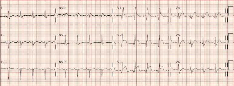
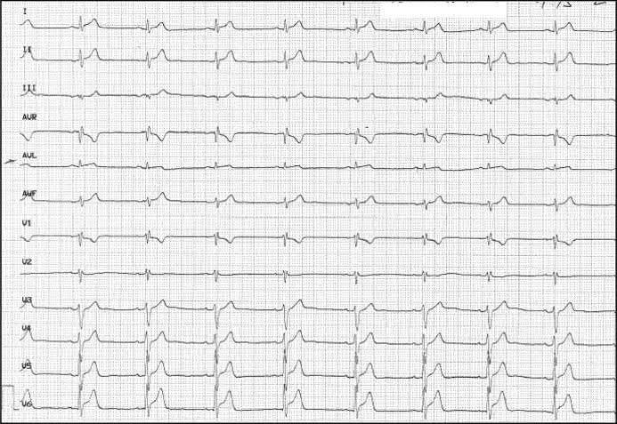
A 60‐year old woman with epigastric discomfort. Her medical history included a treadmill exercise test several years earlier because of negative T waves in V2 to V4 found on a routine
ECG (Figure). The ECG findings were considered a normal variant in a woman and the treadmill test was negative. The ECG shows sinus rhythm with mild biphasic T waves in V2 to V4.
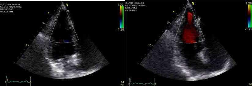
Case 2
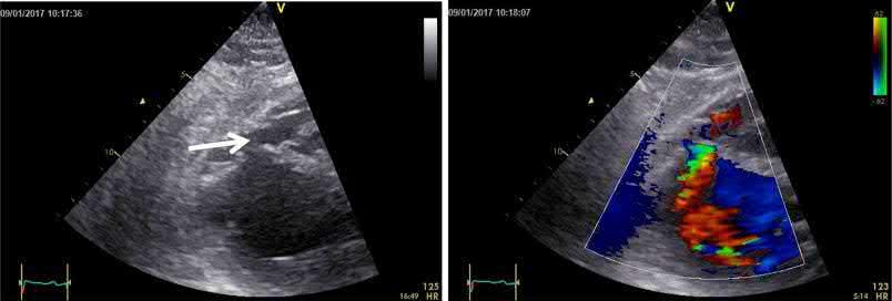
An echocardiogram was performed (left diastole, right systole)
Suggestions for diagnosis:
1) Congenital apical aneur ysm
2) Apical aneur ysm secondary to undiagnosed silent infarction
3) Apical congenital diverticulum
4) Apical hypertrophic cardiomyopathy
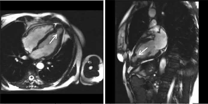
Correct answer: 1
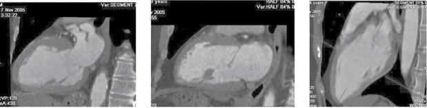
The echocardiogram (of intermediate quality) detected an apical aneurysm. The ventricular aneurysm with a paradoxical expansion during systole and end‐systolic flow pattern from the ventricle to the aneurysm was better demonstrated with CMR (next figure, arrows) (Fiol M, et al. Int J Cardiovasc Imaging. 2015;31: 1261–1262). A “normal variant” is uncommon, but still possible, at the age of 60.
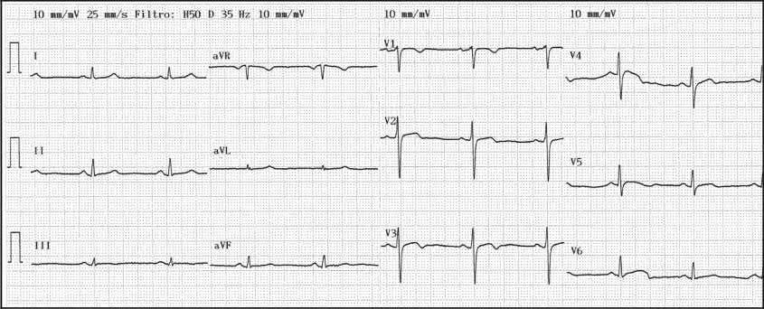
A 68‐year‐old diabetic patient presented with precordial pain radiating to the back. The ECG (Figure) was interpreted as non‐diagnostic.
An aortic CT was performed to rule out aortic dissection.