
Visit to download the full and correct content document: https://ebookmass.com/product/high-voltage-direct-current-transmission-converters-s ystems-and-dc-grids-second-edition-dragan-jovcic/
More products digital (pdf, epub, mobi) instant download maybe you interests ...
Voltage Stability in Electrical Power Systems 1st Edition Farid Karbalaei
https://ebookmass.com/product/voltage-stability-in-electricalpower-systems-1st-edition-farid-karbalaei/

America: The Essential Learning Edition (Second High School Edition) Second High School Edition – Ebook PDF Version
https://ebookmass.com/product/america-the-essential-learningedition-second-high-school-edition-second-high-school-editionebook-pdf-version/

High-Entropy Alloys(Second Edition) B.S. Murty
https://ebookmass.com/product/high-entropy-alloyssecond-editionb-s-murty/

High Performance Computing: Modern Systems and Practices Thomas Sterling
https://ebookmass.com/product/high-performance-computing-modernsystems-and-practices-thomas-sterling/

Deterministic and Stochastic Modeling in Computational Electromagnetics Dragan Poljak
https://ebookmass.com/product/deterministic-and-stochasticmodeling-in-computational-electromagnetics-dragan-poljak/


Must Know High School Chemistry, Second Edition
John T. Moore
https://ebookmass.com/product/must-know-high-school-chemistrysecond-edition-john-t-moore/
Electric Motor Control Sang-Hoon Kim
https://ebookmass.com/product/electric-motor-control-sang-hoonkim/
Electric Motors and Control Systems, Second Edition Frank
D. Petruzella
https://ebookmass.com/product/electric-motors-and-controlsystems-second-edition-frank-d-petruzella/
Dynamics of Coupled Systems in High-Speed Railways: Theory and Practice Weihua Zhang
https://ebookmass.com/product/dynamics-of-coupled-systems-inhigh-speed-railways-theory-and-practice-weihua-zhang/

HighVoltageDirectCurrentTransmission
Converters,SystemsandDCGrids
DraganJovcic
UniversityofAberdeen
Aberdeen,UK
SecondEdition
Thiseditionfirstpublished2019
©2019JohnWiley&SonsLtd
EditionHistory
JohnWiley&Sons(1e,2015)
Allrightsreserved.Nopartofthispublicationmaybereproduced,storedinaretrievalsystem,or transmitted,inanyformorbyanymeans,electronic,mechanical,photocopying,recordingorotherwise, exceptaspermittedbylaw.Adviceonhowtoobtainpermissiontoreusematerialfromthistitleisavailable athttp://www.wiley.com/go/permissions.
TherightofDraganJovcictobeidentifiedastheauthorofthisworkhasbeenassertedinaccordance withlaw.
RegisteredOffices
JohnWiley&Sons,Inc.,111RiverStreet,Hoboken,NJ07030,USA
JohnWiley&SonsLtd,TheAtrium,SouthernGate,Chichester,WestSussex,PO198SQ,UK
EditorialOffice
TheAtrium,SouthernGate,Chichester,WestSussex,PO198SQ,UK
Fordetailsofourglobaleditorialoffices,customerservices,andmoreinformationaboutWileyproducts visitusatwww.wiley.com.
Wileyalsopublishesitsbooksinavarietyofelectronicformatsandbyprint-on-demand.Somecontentthat appearsinstandardprintversionsofthisbookmaynotbeavailableinotherformats.
LimitofLiability/DisclaimerofWarranty
Inviewofongoingresearch,equipmentmodifications,changesingovernmentalregulations,andthe constantflowofinformationrelatingtotheuseofexperimentalreagents,equipment,anddevices,thereader isurgedtoreviewandevaluatetheinformationprovidedinthepackageinsertorinstructionsforeach chemical,pieceofequipment,reagent,ordevicefor,amongotherthings,anychangesintheinstructionsor indicationofusageandforaddedwarningsandprecautions.Whilethepublisherandauthorshaveused theirbesteffortsinpreparingthiswork,theymakenorepresentationsorwarrantieswithrespecttothe accuracyorcompletenessofthecontentsofthisworkandspecificallydisclaimallwarranties,including withoutlimitationanyimpliedwarrantiesofmerchantabilityorfitnessforaparticularpurpose.Nowarranty maybecreatedorextendedbysalesrepresentatives,writtensalesmaterialsorpromotionalstatementsfor thiswork.Thefactthatanorganization,website,orproductisreferredtointhisworkasacitationand/or potentialsourceoffurtherinformationdoesnotmeanthatthepublisherandauthorsendorsethe informationorservicestheorganization,website,orproductmayprovideorrecommendationsitmaymake. Thisworkissoldwiththeunderstandingthatthepublisherisnotengagedinrenderingprofessionalservices. Theadviceandstrategiescontainedhereinmaynotbesuitableforyoursituation.Youshouldconsultwitha specialistwhereappropriate.Further,readersshouldbeawarethatwebsiteslistedinthisworkmayhave changedordisappearedbetweenwhenthisworkwaswrittenandwhenitisread.Neitherthepublishernor authorsshallbeliableforanylossofprofitoranyothercommercialdamages,includingbutnotlimitedto special,incidental,consequential,orotherdamages.
LibraryofCongressCataloging-in-PublicationDataAppliedfor
ISBN:9781119566540
CoverDesign:Wiley
CoverImage:CoverpagephotographreproducedwithpermissionofSIEMENS–HVDCProjectBrazil
Setin10/12ptWarnockProbySPiGlobal,Chennai,India 10987654321
Contents
Preface xvii
PartIHVDCwithCurrentSourceConverters 1
1IntroductiontoLineCommutatedHVDC 3
1.1HVDCApplications 3
1.2LineCommutatedHVDCComponents 4
1.3DCCablesandOverheadLines 7
1.3.1Introduction 7
1.3.2Mass-impregnatedCables 7
1.3.3Low-pressureOil-filledCables 7
1.3.4ExtrudedCross-linkedPolyethyleneCables 8
1.4LCCHVDCTopologies 8
1.5LossesinLCCHVDCSystems 10
1.6ConversionofACLinestoDC 10
1.7UltraHighVoltageHVDC 12
2Thyristors 13
2.1OperatingCharacteristics 13
2.2SwitchingCharacteristics 14
2.3LossesinHVDCThyristors 18
2.4ValveStructureandThyristorSnubbers 20
2.5ThyristorRatingSelectionandOverloadCapability 22
3Six-pulseDiodeandThyristorConverter 25
3.1Three-phaseUncontrolledBridge 25
3.2Three-phaseThyristorRectifier 27
3.3AnalysisofCommutationOverlapinaThyristorConverter 28
3.4ActiveandReactivePowerinaThree-phaseThyristorConverter 32
3.5InverterOperation 33
4HVDCRectifierStationModelling,ControlandSynchronisationwith ACSystem 37
4.1HVDCRectifierController 37
4.2Phase-lockedLoop 38
4.3Master-levelHVDCControl 40
5HVDCInverterStationModellingandControl 43
5.1InverterController 43
5.1.1ControlStructure 43
5.1.2ExtinctionAngleControl 43
5.1.3DCVoltageControl 44
5.1.4DCCurrentControlatInverter 45
5.2CommutationFailure 45
6HVDCSystem V–I DiagramsandOperatingModes 49
6.1HVDCEquivalentCircuit 49
6.2HVDC V –I OperatingDiagram 49
6.3HVDCPowerReversal 51
7HVDCAnalyticalModellingandStability 57
7.1IntroductiontoConverterandHVDCModelling 57
7.1.1DetailedSwitchingTransientsModelling 57
7.1.2ModellingwithSwitchings 57
7.1.3AnalyticalDynamicModellingofConverters 58
7.1.4PhasorModelling 58
7.2HVDCAnalyticalModel 58
7.3CIGREHVDCBenchmarkModel 60
7.4ConverterModelling,Linearisation,andGainScheduling 60
7.5ACSystemModellingforHVDCStabilityStudies 64
7.6LCCConverterTransformerModel 67
7.7DCSystemIncludingDCCable 68
7.7.1DCCable/LineModellingasaSingle �� Section 68
7.7.2ControllerModel 69
7.7.3CompleteDCSystemModel 69
7.8AccurateDCCableModelling 70
7.8.1WidebandCableModel 70
7.8.2CableHigher-orderAnalyticalModelinStateSpace 72
7.9HVDC–HVACSystemModel 76
7.10AnalyticalDynamicModelVerification 77
7.11BasicHVDCDynamicAnalysis 77
7.11.1EigenvalueAnalysis 77
7.11.2EigenvalueSensitivityStudy 77
7.11.3InfluenceofPLLGains 79
7.12HVDCSecondHarmonicInstability 80
7.13100HzOscillationsontheDCSide 82
8HVDCPhasorModellingandInteractionswithACSystem 83
8.1ConverterandDCSystemPhasorModel 83
8.2PhasorACSystemModelandInteractionwithDCSystem 84
8.3InverterACVoltageandPowerProfileasDCCurrentisIncreasing 86
8.4InfluenceofConverterExtinctionAngle 88
8.5InfluenceofShuntReactivePowerCompensation 88
8.6InfluenceofLoadattheConverterTerminals 88
8.7InfluenceofOperatingMode(DCVoltageControlMode) 88
8.8RectifierOperatingMode 90
9HVDCOperationwithWeakACSystems 95
9.1Introduction 95
9.2ShortCircuitRatioandEquivalentShortCircuitRatio 95
9.2.1DefinitionofSCRandESCR 95
9.2.2OperatingDifficultieswithLowSCRSystems 98
9.3BackgroundonPowerTransferBetweenTwoACSystems 99
9.4PhasorStudyofConverterInteractionswithWeakACSystems 101
9.5SystemDynamics(SmallSignalStability)withLowSCR 101
9.6ControlandMainCircuitSolutionsforWeakACGrids 102
9.7LCCHVDCwithSVC 103
9.8CapacitorCommutatedConvertersforHVDC 104
9.9ACSystemwithLowInertia 106
10FaultManagementandHVDCSystemProtection 111
10.1Introduction 111
10.2DCLineFaults 111
10.3ACSystemFaults 113
10.3.1RectifierACFaults 113
10.3.2InverterACFaults 114
10.4InternalFaults 115
10.5SystemReconfigurationforPermanentFaults 116
10.6OvervoltageProtection 119
11LCCHVDCSystemHarmonics 121
11.1HarmonicPerformanceCriteria 121
11.2HarmonicLimits 122
11.3ThyristorConverterHarmonics 123
11.4HarmonicFilters 124
11.4.1Introduction 124
11.4.2TunedFilters 126
11.4.3DampedFilters 128
11.5Non-characteristicHarmonicReductionUsingHVDCControls 132
BibliographyPartI:LineCommutatedConverterHVDC 133
PartIIHVDCwithVoltageSourceConverters 137
12VSCHVDCApplicationsandTopologies,PerformanceandCost ComparisonwithLCCHVDC 139
12.1ApplicationofVoltageSourceConvertersinHVDC 139
12.2ComparisonwithLCCHVDC 141
12.3HVDCTechnologyLandscape 142
12.4OverheadandSubsea/UndergroundVSCHVDCTransmission 143
12.5DCCableTypeswithVSCHVDC 147
12.6MonopolarandBipolarVSCHVDCSystems 147
12.7VSCHVDCConverterTopologies 148
12.7.1HVDCwithTwo-levelVoltageSourceConverter 148
12.7.2HVDCwithNeutralPointClampedConverter 150
12.7.3MMCVSCHVDCTransmissionSystems 151
12.7.4MMCHVDCBasedonFBTopology 153
12.8VSCHVDCStationComponents 155
12.8.1ACCB 155
12.8.2VSCConverterTransformer 155
12.8.3VSCConverterACHarmonicFilters 156
12.8.4DCCapacitors 156
12.8.5DCFilter 157
12.8.6Two-levelVSCHVDCValves 158
12.8.7MMCValvesandCells 159
12.9ACInductors 160
12.10DCInductors 161
13IGBTSwitchesandVSCConverterLosses 165
13.1IntroductiontoIGBTandIGCT 165
13.2GeneralVSCConverterSwitchRequirements 166
13.3IGBTTechnology 166
13.3.1IGBTOperatingCharacteristics 167
13.3.2FastRecoveryAnti-parallelDiode 171
13.4HighPowerIGBTDevices 171
13.5IEGTTechnology 172
13.6LossesCalculation 173
13.6.1ConductionLossModelling 173
13.6.2SwitchingLossModelling 174
13.7BalancingChallengesinTwo-levelIGBTValves 178
13.8SnubbersCircuits 179
14Single-phaseandThree-phaseTwo-levelVSCConverters 181
14.1Introduction 181
14.2Single-phaseVSC 181
14.3Three-phaseVSC 184
14.4Square-wave,Six-pulseOperation 185
14.4.1180∘ Conduction 185
14.4.2120∘ Conduction 188
15Two-levelPWMVSCConverters 193
15.1Introduction 193
15.2PWMModulation 193
15.2.1MultipulsewithConstantPulseWidth 193
15.2.2ModulatingSignal 194
15.3SinusoidalPulseWidthModulation 195
15.4ThirdHarmonicInjection 197
15.5SelectiveHarmonicEliminationModulation 198
15.6ConverterLossesforTwo-levelSPWMVSC 198
15.7HarmonicswithPWM 201
15.8ComparisonofPWMModulationTechniques 203
16MultilevelVSCConvertersinHVDCApplications 205
16.1Introduction 205
16.2ModulationTechniquesforMultilevelConverters 207
16.3NeutralPointClampedMultilevelConverter 208
16.4HalfBridgeMMC 210
16.4.1OperatingPrinciplesofHalf-bridgeMMC 210
16.4.2CapacitorVoltageBalancing 212
16.4.3MMCCellCapacitance 214
16.4.4MMCArmInductance 215
16.4.5MMCwithFundamentalFrequencyModulation 218
16.4.6MMCwithPWMModulation 218
16.5FullBridgeMMC 222
16.5.1OperatingPrinciples 222
16.6ComparisonofMultilevelTopologies 224
17Two-levelVSCHVDCModelling,Control,andDynamics 227
17.1PWMTwo-levelConverterAverageModel 227
17.1.1ConverterModelinanABCFrame 227
17.1.2ConverterModelintheABCFrameIncludingBlockedState 229
17.2Two-levelPWMConverterModelinDQFrame 230
17.3VSCConverterTransformerModel 231
17.4Two-levelVSCConverterandACGridModelintheABCFrame 231
17.5Two-levelVSCConverterandACGridModelinaDQRotatingCoordinate Frame 232
17.6VSCConverterControlPrinciples 233
17.7TheInnerCurrentControllerDesign 234
17.7.1ControlStrategy 234
17.7.2DecouplingControl 234
17.7.3CurrentFeedbackControl 235
17.7.4ControllerGains 236
17.8OuterControllerDesign 237
17.8.1ACVoltageControl 237
17.8.2PowerControl 238
17.8.3DCVoltageControl 239
17.8.4ACGridSupport 240
17.9CompleteTwo-levelVSCConverterController 240
17.10SmallSignalLinearisedVSCHVDCModel 242
17.11SmallSignalDynamicStudies 242
17.11.1DynamicsofWeakACSystems 242
17.11.2ImpactofPLLGainsonRobustness 244
18Two-levelVSCHVDCPhasor-domainInteractionwithACSystemsand PQOperatingDiagrams 247
18.1PowerExchangeBetweenTwoACVoltageSources 247
18.2ConverterPhasorModelandPowerExchangewithanACSystem 249
18.3PhasorStudyofVSCConverterInteractionwithACSystem 252
18.3.1TestSystem 252
18.3.2AssumptionsandConverterLimits 252
18.3.3Case1:ConverterVoltagesAreKnown 253
18.3.4Case2:ConverterCurrentsareKnown 254
18.3.5Case3:PCCVoltageisKnown 254
18.4OperatingLimits 254
18.5DesignPointSelection 255
18.6InfluenceofACSystemStrength 258
18.7InfluenceofACSystemImpedanceAngle(X s /Rs ) 258
18.8InfluenceofTransformerReactance 258
18.9InfluenceofConverterControlModes 262
18.10OperationwithVeryWeakACSystems 262
19HalfBridgeMMC:Dimensioning,Modelling,Control,andInteraction withACSystem 269
19.1BasicEquationsandSteady-stateControl 269
19.2Steady-stateDimensioning 272
19.3HalfBridgeMMCNon-linearAverageDynamicModel 275
19.4Non-linearAverageValueModelIncludingBlockedState 276
19.5HBMMCHVDCStart-upandChargingMMCCells 278
19.6HBMMCDynamicDQFrameModelandPhasorModel 279
19.6.1Assumptions 279
19.6.2ZeroSequenceModel 282
19.6.3FundamentalFrequencyModelinDQFrame 282
19.6.4SecondHarmonicModelinthe D2Q2 CoordinateFrame 284
19.7SecondHarmonicofDifferentialCurrent 286
19.8CompleteMMCConverterDQModelinMatrixForm 286
19.9Second-harmonicCirculatingCurrentSuppressionController 287
19.10SimplifiedDQFrameModelwithCirculatingCurrentController 290
19.11PhasorModelofMMCwithCirculatingCurrentSuppression Controller 295
19.12SimplifiedDynamicMMCModelUsingEquivalentSeriesCapacitor C MMC 296
19.13FullDynamicAnalyticalHBMMCModel 300
19.14HBMMCControllerandArmVoltageControl 301
19.15MMCTotalSeriesReactanceandComparisonwithTwo-levelVSC 304
19.16MMCInteractionwithACSystemandPQOperatingDiagrams 306
20FullBridgeMMCConverter:Dimensioning,Modelling,and Control 309
20.1FBMMCArmVoltageRange 309
20.2FullBridgeMMCConverterNon-linearAverageModel 309
20.3FBMMCNon-linearAverageModelIncludingBlockedState 310
20.4FullBridgeMMCCellCharging 312
20.5HybridMMCDesign 313
20.5.1OperationUnderLowDCVoltage 313
20.5.2OvermodulationRequirements 314
20.5.3CellVoltageBalancingUnderLowDCVoltage 315
20.5.4OptimalDesignofFullBridgeMMC 315
20.6FullBridgeMMCDCVoltageVariationUsingaDetailedModel 318
20.7FBMMCAnalyticalDynamic DQ Model 320
20.7.1ZeroSequenceModel 320
20.7.2FundamentalFrequencyModel 321
20.8SimplifiedFBMMCModel 321
20.9FBMMCConverterController 322
21MMCConverterUnderUnbalancedConditions 325
21.1Introduction 325
21.2MMCBalancingControllerStructure 326
21.3BalancingBetweenPhases(HorizontalBalancing) 326
21.4BalancingBetweenArms(VerticalBalancing) 328
21.5SimulationofBalancingControls 330
21.6OperationwithUnbalancedACGrid 332
21.6.1DetectingPositiveandNegativeSequenceComponents 332
21.6.2ControllingGridCurrentSequenceComponentswithMMC 336
22VSCHVDCUnderACandDCFaultConditions 339
22.1Introduction 339
22.2FaultsontheACSystem 339
22.3DCFaultswithTwo-levelVSC 340
22.4InfluenceofDCCapacitors 345
22.5VSCConverterModellingUnderDCFaultsandVSCDiodeBridge 345
22.5.1VSCDiodeBridgeAverageModel 345
22.5.2PhasorModelofVSCDiodeBridgeUnderDCFault 348
22.5.3SimpleExpressionforVSCDiodeBridgeSteady-stateFaultCurrent Magnitude 351
22.6VSCConverterModeTransitionsasDCVoltageReduces 352
22.7DCFaultswithHalfBridgeModularMultilevelConverter 354
22.8FullBridgeMMCUnderDCFaults 356
23VSCHVDCApplicationForACGridSupportandOperationwith PassiveACSystems 359
23.1VSCHVDCHighLevelControlsandACGridSupport 359
23.2HVDCEmbeddedInsideanACGrid 360
23.3HVDCConnectingTwoSeparateACGrids 361
23.4HVDCinParallelwithAC 361
23.5OperationwithaPassiveACSystemandBlackStartCapability 362
23.6VSCHVDCOperationwithOffshoreWindFarms 362
23.7VSCHVDCSupplyingPowerOffshoreandDrivingaMW-SizeVariable SpeedMotor 365
BibliographyPartII:VoltageSourceConverterHVDC 366
PartIIIDCTransmissionGrids 371
24IntroductiontoDCGrids 373
24.1DCversusACTransmission 373
24.2Terminology 374
24.3DCGridPlanning,Topology,andPowerTransferSecurity 375
24.4TechnicalChallenges 376
24.5DCGridBuildingbyMultipleManufacturers–Interoperability 376 24.6EconomicAspects 377
25DCGridsWithLineCommutatedConverters 379
25.1MultiterminalLCCHVDC 379
25.2Italy–Corsica–SardiniaMultiterminalHVDCLink 380
25.3ConnectingtheLCCConvertertoaDCGrid 381
25.3.1PowerReversal 381
25.3.2DCFaults 382
25.3.3ACFaults 383
25.4ControlofLCCConvertersinDCGrids 383
25.5ControlofLCCDCGridsThroughDCVoltageDroopFeedback 384
25.6ManagingLCCDCGridFaults 385
25.7ReactivePowerIssues 387
25.8EmployingLCCConverterStationsinEstablishedDCGrids 387
26DCGridswithVoltageSourceConvertersandPowerFlowModel 389
26.1ConnectingaVSCConvertertoaDCGrid 389
26.1.1PowerReversalandControl 389
26.1.2DCFaults 389
26.1.3ACFaults 389
26.2MultiterminalVSCHVDCOperatinginChina 390
26.3DCGridPowerFlowModel 390
26.4DCGridPowerFlowUnderDCFaults 395
27DCGridControl 399
27.1Introduction 399
27.2FastLocalVSCConverterControlinDCGrids 399
27.3DCGridDispatcherwithRemoteCommunication 401
27.4Primary,Secondary,andTertiaryDCGridControl 402
27.5DCVoltageDroopControlforVSCConvertersinDCGrids 403
27.6Three-levelControlforVSCConverterswithDispatcherDroop 405
27.6.1Three-levelControlforVSCConverters 405
27.6.2DispatcherController 406
27.7PowerFlowAlgorithmWhenDCPowersareRegulated 406
27.8PowerFlowandControlStudyofCIGREDCGridTestSystem 411
27.8.1CIGREDCGridTestSystem 411
27.8.2PowerFlowAfterOutageoftheLargestTerminal 413
28DCCircuitBreakers 417
28.1Introduction 417
28.2ChallengeswithDCCircuitOpening 417
28.2.1DCCurrentCommutation 417
28.2.2DCCurrentSuppressionandDissipationofEnergy 418
28.3DCCBOperatingPrinciplesandaSimpleModel 418
28.4DCCBPerformanceRequirements 420
28.4.1OpeningSpeed 420
28.4.2DCCBRatingsandSeriesInductors 420
28.4.3BidirectionalCurrentInterruption 421
28.4.4MultipleOpen/closeOperationsinaShortTime 421
28.4.5Losses,Size,andWeight 421
28.4.6Standardisation 421
28.5PracticalHVDCCBs 422
28.6MechanicalDCCB 422
28.6.1OperatingPrinciplesandConstruction 422
28.6.2MathematicalModelandDesignPrinciples 424
28.6.3TestCircuitforDCCBSimulation 426
28.6.4SimulationofDCFaultClearing 427
28.6.5NegativeFaultCurrentInterruption 427
28.6.6MultipleOpen/closeOperationsinaShortTime 428
28.6.7MechanicalDCCBforHighVoltages 429
28.7Semiconductor-basedDCCB 430
28.7.1TopologyandDesign 430
28.7.2Self-protectionofSemiconductorValves 432
28.7.3SimulationofFaultCurrentInterruption 432
28.8HybridDCCB 434
28.8.1TopologyandDesign 434
28.8.2HybridDCCBforHighVoltages 435
28.8.3SimulationofFaultCurrentInterruption 436
28.8.4BidirectionalOperation 437
28.8.5FaultCurrentLimiting 438
29DCGridFaultManagementandProtectionSystem 441
29.1Introduction 441
29.2FaultCurrentComponentsinDCGrids 442
29.3DCSystemProtectionCoordinationwithACSystemProtection 444
29.4DCGridProtectionSystemDevelopment 445
29.5DCGridProtectionSystemBasedonLocalMeasurements 446
29.5.1ProtectionBasedonDCCurrentandCurrentDifferential 446
29.5.2RateofChangeofVoltageProtection 447
29.6BlockingMMCConvertersUnderDCFaults 450
29.7DifferentialDCGridProtectionStrategy 452
29.8SelectiveProtectionforStar-topologyDCGrids 455
29.9DCGridswithDCFault-tolerantVSCConverters 456
29.9.1GridTopologyandStrategy 456
29.9.2VSCConverterwithIncreasedACCouplingReactors 457
29.9.3LCLVSCConverter 459
29.9.4VSCConverterwithFaultCurrentLimiter 461
29.10DCGridswithFullBridgeMMCConverters 461
30HighPowerDC/DCConvertersandDCPowerFlowControlling Devices 465
30.1Introduction 465
30.2PowerFlowControlUsingSeriesResistors 466
30.3Low-stepping-ratioDC/DCConverters(DCChoppers) 469
30.3.1ConverterTopology 469
30.3.2ConverterController 470
30.3.3DC/DCChopperAverageValueModel 471
30.3.4H-BridgeDC/DCChopper 473
30.4Non-isolatedMMC-basedDC/DCConverter(M2DC) 473
30.4.1Introduction 473
30.4.2ModellingandDesign 474
30.4.3DesignExampleandComparisonwithMMCAC/DC 477
30.4.4ControllerDesign 479
30.4.5SimulationResponses 480
30.5DC/DCConverterswithDCPolarityReversal 484
30.6High-stepping-ratioIsolatedDC/DCConverter(DualActiveBridge DC/DC) 484
30.6.1Introduction 484
30.6.2ModellingandControl 486
30.6.3SimulatedResponses 487
30.7High-stepping-ratioLCLDC/DCConverter 490
30.8BuildingDCGridswithDC/DCConverters 492
30.9DCHubs 495
30.10DevelopingDCGridsUsingDCHubs 496
30.11NorthSeaDCGridTopologies 496
BibliographyPartIII:DCTransmissionGrids 500
AppendixAVariableNotations 503
AppendixBAnalyticalBackgroundtoRotatingDQFrame 505
B.1TransformingACVariablestoaDQFrame 505
B.2DerivativeofanOscillatingSignalinaDQFrame 507
B.3TransforminganACSystemDynamicEquationtoaDQFrame 507
B.4Transformingan n-OrderStateSpaceACSystemModeltoaDQFrame 509
B.5Static(Steady-state)ModelinginaRotatingDQCoordinateFrame 510
B.6RepresentingtheProductofOscillatingSignalsinaDQFrame 511
B.7RepresentingPowerinDQFrame 512
AppendixCSystemModelingUsingComplexNumbersandPhasors 515
AppendixDSimulinkExamples 517
D.1Chapter3Examples 517
D.2Chapter5Examples 517
D.3Chapter6Examples 519
D.4Chapter8Examples 521
D.5Chapter14Examples 523
D.6Chapter16Examples 524
D.7Chapter17Examples 527
Index 535
Preface
Atthetimeofwritingthisbookthereareover200highvoltagedirectcurrent(HVDC) linksinstalledworldwide.Thelargestinstallationsoperateat ±800kVDCvoltagewhile thehighestDCcurrentratingsareover4500A.Althoughalternatingcurrentwasthe predominantmethodfortransmittingelectricalenergyduringthetwentiethcentury, HVDChasnowbeendemonstratedtobethebestsolutionformanyspecificapplication areasandthenumberofinstallationsperyearisconstantlyincreasingatthebeginningofthetwenty-firstcentury.Despitesignificantconverterstationcosts,HVDCis techno-economicallypreferredinmanygeneralapplications:
• long-distancelarge-scalepowertransfer;
• subseaandlong-distancecablepowertransmission;
• interconnectingasynchronousACsystems,orsystemswithdifferentfrequencies;
• controllablepowertransferbetweendifferentnodesinanelectricitymarketormarkets;
• ACgridstabilitysupport,ancillaryserviceprovision,andresiliencefromblackouts;
• connectingisolatedsystemslikeoffshorewindfarmsoroilplatforms.
DCtransmissiontechnologywasusedinmanyinstancesintheveryearlypower systems,butthemodernHVDCtransmissionbeganwiththe1954Sweden–Gotland installation.Thissystem,andalloftheotherHVDCscommissioneduntilthemid 1970s,wasbasedonmercuryarcvalves.Significanttechnicaladvancecamewith theintroductionofsolid-statevalves(thyristors)althoughtheyonlysupporttheline commutatedconverterconcept.Inthefirstdecadeofthetwenty-firstcenturythere hasbeenveryrapiddevelopmentoffundamentallynewtechnologiesandincreasing demandforHVDCtechnology.Theintroductionofvoltagesourceconverters(VSCs) requiresnewvalvesthatutiliseinsulatedgatebipolartransistorsandalsonewprotectionandcontrolapproaches.Themodularmultilevelconvertershaveeventually emergedasthemostcost-effectiveVSCconverterconceptwhichpracticallyeliminates filteringneedswithHVDCandremovesvoltagelimitswithVSCvalves.Modular multilevelconverterHVDCnowadayshaslowlosseswhicharecomparablewiththose ofthyristorHVDCandnewtechnologiesareemergingthatopenuppossibilitiesfor widerapplicationareas.
Intheseconddecadeofthetwenty-firstcentury,ithasbecomeapparentthatDC transmissiongridsarebothaviablesolutiontolarge-scaleenergychallengesandtechnicallyfeasible.Theprimaryapplicationdriversarecomingfromtheinitiativeslike theNorthSeaDCgrid,Medtech,Desertec,EuropeanOverlaySupergridandvarious
projectsinChina,wheretwomultiterminalVSCHVDCsystemsarealreadyoperating. ItisacceptedthattheDCtransmissiongridswillhavesimilarorbetterlevelsofreliability andtechnicalperformancetotheACtransmissionsystem.Thislevelofperformance, securityandreliabilityistechnicallyfeasible,althoughinmanyaspectsDCgridswill besubstantiallydifferentfromtraditionalACsystems.ThedevelopmentofDCgrids bringssignificanttechnicaladvancesinHVDCtechnologies,inparticularrelatedtoDC CB(circuitbreakers),DC/DCconvertersandDCprotectionsystems,andsubstantial furtherresearchanddevelopmentisanticipated.
NowadaysHVDCandDCgridsareassociatedwithgreenenergy,asfacilitatorsof large-scalerenewableenergyplants.Thishelpswiththepublicacceptanceandimage, andfacilitatesfurtherinvestmentsinlargepublicprojects.AlsoHVDCisperceived asatechnologythatavoidspylons,byusinglongundergroundcables,whichfurther strengthensargumentsforfuturefundingdecisions.
Thetimingofthisbookis,therefore,instepwithacceleratedinterestinHVDCand projectedsignificantincreaseandexpansioninapplications.Thebookisorganised intothreepartsinordertostudyallthreemajorHVDCconceptsandcurrentresearch developments:linecommutatedHVDC,VSCHVDCandDCgridsincludingcurrent researchdevelopments.Eachpartwillreviewtheoreticalconceptsfirstandanalyse aspectsoftechnology,interactionwithACgrids,modelling,control,faultsandprotectionwithparticularemphasisonpracticalimplementationaspectsandreported operationalissues.Thetechnologydescribedinthefirsttwopartsislargelybasedon theoperatingHVDCsystems,whilethetopicofDCgridsisgroundedinthesignificant volumeofresearchatmanyinstitutions.
ThetechnicalfieldofHVDCtransmissionandDCgridsstraddlesthreemajortraditionalelectricalengineeringdisciplines:
Powertransmissionengineering –theimpactofHVDCsystemsontheconnectingAC transmissionsystemsandthenationalgridsisofprimaryimportance.Theinfluence ofACsystemsonHVDCisalsoofsignificanceintermsoftechnicalperformance, stability,protectionandpowertransfersecurityingeneral.Theharmonicinteraction willbestudiedinsomedepth.
Powerelectronics –eachHVDClinkinvolvesatleasttwoAC/DCconverterswhileDC gridswillhavemanymoreincludingsemiconductorDCCBsandDC/DCconverters. Theseconvertershavesimilarfeaturestothetraditionallow-powerconvertersbut manyotheruniquerequirementsexisttodevelopvalvesandconverterassemblies capableofsustainingupto800kVandperhapsover4500A.Theprotectionofvalves andconvertersisveryimportantanddefiningpowerelectronicsfeatureinHVDC.
Controlengineering –modellingandsimulationofHVDCisessentialfordesign andoperationandseveraldifferentmodellingapproachesexistdependingonthe modelapplication.Inparticular,becauseofhighcostsofHVDCtestingandthe consequencesofanydesignissues,modelaccuracyandsimulationspeedplaya crucialroleinthesystemdesign.ThecontrolsystemsforHVDChaveevolvedinto verycomplextechnologieswhicharealwaysmultivariableandnon-linearwith multiplecontrollayers.
Theabovethreetechnicaldisciplineswillbeemployedinthisbookinordertoanalyse alloftheessentialtechnicalaspectsofHVDCandDCgrids,aimingtofacilitatelearning byresearchersandengineersinterestedinthisfield.
ThematerialinthisbookincludescontributionsfrommanyHVDCresearchersand engineers,anditisdevelopedfromresearchprojectsfundedbyseveralresearchcouncils andprivatefirms.Moreimportantly,thestudiesareinspiredandbuiltonpreviouswork bynumerousHVDCengineersandresearchers.
TheauthorwouldliketoexpressgratitudetoDrKhaledAhmedforsignificationcontributiontothefirsteditionofthismanuscript,whichhasservedasthebasisforthe secondedition.TheauthorisparticularlythankfultoALSTOMGrid,UK,formaking theircomprehensivereport‘HVDCConnectingtothefuture’availabletotheauthors, aswellastoSiemens,Germany,andABB,Sweden,fortheirHVDCphotographs.Iam alsoindebtedtoalloftheresearchersattheUniversityofAberdeenHVDCresearch centreandinparticulartoDr.WeixingLin,Dr.AliJamshidifar,Dr.MasoodHajian,Dr. HuibinZhang,Mr.StefanKovacevic,andDr.LuZhangfortheircontributions.
SpecialthanksarereservedforSSE,Scotland,and,inparticular,toAndrewRobertson, fortheirsupportoftheHVDCcourseattheUniversityofAberdeen,whichprovided substantialmaterialforthisbook.
Theauthorisfurthergratefultothefollowingorganisations,whichhavesupported relatedresearchstudiesattheUniversityofAberdeen:
• EPSRC(EngineeringandPhysicalSciencesResearchCouncil)UK;
• ERC(EuropeanResearchCouncil),FP7Ideasprogram;
• RTE(RéseaudeTransportd’Électricité),France;
• EUHorizon2020.
January2019
DraganJovcic
HVDCwithCurrentSourceConverters
1.1HVDCApplications
Thyristor-basedhighvoltagedirectcurrent(HVDC)transmissionhasfoundapplication inmorethan150point-to-pointworldwideinstallations,andineachcasehasprovento betechnologicallyand/oreconomicallysuperiortoalternatingcurrent(AC)transmission.TypicalHVDCapplicationscanbegroupedasfollows:
• Submarinepowertransmission.ACcableshavelargecapacitanceandforcablesover 40–70kmthereactivepowercirculationbecomesunacceptable.Thisdistancecanbe extendedsomewhatwithreactivepowercompensation.ForlargerdistancesHVDCis moreeconomical.Agoodexampleisthe580km,700MW, ±450kVNorNedHVDC betweenNorwayandTheNetherlands.
• Long-distanceoverheadlines.LongAClinesrequirevariablereactivepowercompensation.Typically600–800kmisbreakevendistance,andforlongerdistancesHVDC ismoreeconomical.Agoodexampleisthe1360km,3.1GW, ±500kVPacificDC intertiealongthewestcostoftheUSA.
• InterconnectingtwoACnetworksofdifferentfrequencies.Agoodexampleisthe 500MW, ±79kVback-to-backMeloHVDCbetweenUruguayandBrazil.The Uruguaysystemoperatesat50HzwhereastheBrazilnationalgridrunsat60Hz.
• InterconnectingtwounsynchronisedACgrids.IfthephasedifferencebetweentwoAC systemsislargetheycannotbedirectlyconnected.Atypicalexampleisthe150MW, ±42kVMcNeillback-to-backHVDClinkbetweenAlbertaandSaskatchewaninterconnectingasynchronouseasternandwesternAmericansystems.
• ControllablepowerexchangebetweentwoACnetworks(fortrading).TheACpower flowisdeterminedbythelineimpedances,andthereforetheACpowerflowcannot bedirectlycontrolledineachline.IncomplexACnetworksitiscommontoobserve looppowerfloworevenoverloadingorunder-utilisationofsomeAClines.Many HVDCsystemsparticipatedirectlyintradingpowerandonetypicalexampleisthe 200MW, ±57kVHighgateHVDCbetweenQuebecandVermont.
ThereareotherlesscommonapplicationsofLCC(linecommutatedconverter)HVDC technologyandthe300MWLevisDe-IcerHVDCprojectwillbementioned.Here,one standardHVDCconverterstation(converterfromStaticVarCompensator)isusedto provideveryhighDCofupto7920A(feedingessentiallyaDCshortcircuit)toenable heatingofremoteCanadianoverheadlinesinordertopreventicebuild-up.
HighVoltageDirectCurrentTransmission:Converters,SystemsandDCGrids, SecondEdition.DraganJovcic. ©2019JohnWiley&SonsLtd.Published2019byJohnWiley&SonsLtd.
HVDC station costs
HVAC station costs

Beakeven distance
For cables 40–70 km
For overhead lines 600–800 km
Figure1.1 HVDCandHVACtransmissioncostcomparison.
AnimportantargumentforselectingHVDCinsteadofACforanewtransmission lineisalsothecontributiontoshortcircuitlevel.HVDCisabletolimitthefaultcurrent andthereforewillnotrequireupgradeofsubstationequipment.
Figure1.1showsacomparisonofcostsforDCandACtransmissionlines.Inthecase ofHVDCtheinitialcapitalinvestmentismuchhigherbecauseoftheconvertercosts. Asthetransmissiondistanceincreases,thebenefitsofDCcompensateforthecapital investmentandatcertaindistancethetotalcostoftheHVDCsystemissameasthatof theACline.Thebreakevendistanceisintherangeof40–70kmforsubmarinecables andintherangeof600–800kmforoverheadlines.
Figure1.2showsanaerialviewofterminalstationofthe500MWMoyleHVDClink. ThisHVDCenablescontrollablebidirectionalpowerexchangebetweenScotlandand NorthernIreland.
1.2LineCommutatedHVDCComponents
Figure1.3showsatypicallinecommutatedconverterHVDCschematicinterconnectingACsystems1and2.ItconsistsoftwoterminalsandaDClinebetweenthem.Each terminal(converterstation)includesconverters,transformersfilters,reactivepower equipment,acontrolstationandarangeofothercomponents.TherearetwoDClines inthisfigurewhileonelineisatgroundpotential.
AsshowninFigure1.3,themajorcomponentsofanHVDCsysteminclude:
• Converters.Thesetypicallyincludeatleastonesix-pulsethyristor(Graetz)bridge. Eachbridgeconsistsofsixthyristorvalveswhichinturncontainhundredsof individualthyristors.Withlargesystems,bridgesareconnectedinseriesin12-or 24-pulseconfiguration.These12-pulseconverterscanbeconnectedintopolesor bipoles.
• Convertertransformers.Theseareofaspecialconvertertransformertypethatis somewhatmoreexpensivethantypicalACtransformersofthesamerating.The convertertransformersaredesignedtooperatewithhighharmoniccurrentsandto withstandACandDCvoltagestress.Inmostcasesconvertertransformerswillhave tapchangersthatenableoptimisationofHVDCoperation.

Figure1.2 TerminalstationofMoyleHVDCinterconnector(bipole2 × 250MW, ±250kV,with light-triggeredthyristors,commissionedin2001).Source:ReproducedwithpermissionofSiemens.
• SmoothingreactorsontheDCside.ThetypicalinductanceforlargeHVDCsystemsis 0.1–0.5H,whichisdeterminedconsideringDCfaultresponses,commutationfailure anddynamicstability.Thereactorsareofair-core,naturalair-coolingtypeandcosts aremodest.
• Reactivepowercompensation.Theconverterstypicallyrequirereactivepowerof around60%oftheconverterpowerrating.Alargeportionofthisreactivepoweris suppliedbyfilterbanksandtheremainingpartbycapacitorbanks.Sincereactive powerdemandvarieswithDCpowerlevel,thecapacitorsarearrangedinswitchable banks.
• Filters.Atypical12-pulsethyristorterminalwillrequire11th,13th,23rd,and25th filtersontheACside.Inaddition,ahigh-passfilterisfrequentlyincluded.Insome casesthirdharmonicfiltersarerequired.SomeHVDCsystemswithoverheadlines furtheremployDC-sidefilters.
• Electrodes.SomeoldHVDCsystemsnormallyoperatewithsea/groundreturnbut mostgridoperatorsnolongerallowpermanentgroundcurrentsforenvironmentalreasons.Electrodesdemandongoingmaintenancecosts.Manynewbipolar systemsareallowedtooperatewithgroundreturnathalfpowerforashorttime (10–20minutes)incaseoflossofanHVDCpole.Thisimpliesthatelectrodesare designedforfullcurrent,butcarrynocurrentinnormaloperation.
• Controlandcommunicationsystem.Eachterminalwillhaveacontrolsystemconsistingofseveralhierarchicallayers.Adedicatedcommunicationlinkbetweenterminals isneededbutspeedisnotcritical.AnHVDClinkcanoperateincaseofalossof communicationlink.
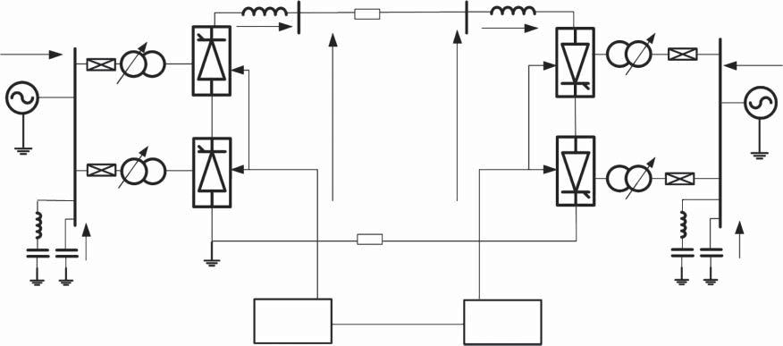
Figure1.3 TypicalHVDCschematic(12-pulsemonopolewithmetallicreturn).
1.3DCCablesandOverheadLines
1.3.1Introduction
LCCHVDChasbeenimplementedusingbothoverheadlinesandunderground/subsea DCcables.Overheadlinesarevulnerabletolightningstrikes,whichareessentiallyDC faults.NeverthelessDCfaultsonlycausetransientdisturbancesandtheyarereadily managedbyLCCHVDC.Contrarytovoltagesourceconverter(VSC)HVDC,aswillbe discussedlater,DCfaultscausemuchmoreseriousdisturbances.
Themostcommoncabletechnologiesthathavebeendevelopedsofarinclude:
• mass-impregnatedcables(MI);
• low-pressureoil-filledcables;and
• extrudedcross-linkedpolyethylene(XLPE)cables.
Theabovecabletypeshavesameconductorsandtheirconstructionissimilarbut theinsulationmaterialsaresubstantiallydifferent.Thecablevoltageratingdependson thecapabilityoftheinsulation(dielectric)material,andtherearetwomaintypesof dielectrics,namelylappedandextruded.
1.3.2Mass-impregnatedCables
Since1895,MIcableshavebeenusedinpowertransmission.InMIcables,thedielectricislappedpaperinsulation,whichisimpregnatedwithhigh-viscosityfluid.Forbulk powertransmission,MIcablesarestillthemostsuitablesolutionbecauseoftheircapacitytoworkupto500kVDC.AlsothesecablestoleratefastDCvoltagepolarityreversal, makingthemsuitableforLCCHVDC.TheMIcableshavealongrecordoffieldoperationatavoltageof500kVandtransmissioncapacityofover800MW(1.6kA)for monopoleHVDC,but600kVand1000MWratingshavebeenannounced.Therefore anHVDCinbipolarconnectionisabletotransmitupto2000MWwithMIcables. Thesecablescanbeinstalledatdepthsofupto1000mbelowsealevelandwithnearly unlimitedtransmissionlength.Thecapacityofthissystemislimitedbytheconductortemperature,whichcanreduceoverloadcapabilities.The580km-long,700MW, 450kVcablelinkbetweenNorwayandTheNetherlandsrepresentsthehighestpower andlongestlengthforthiscabletype.Atpresentmost(over90%)submarinecablesare oftheMItype.
1.3.3Low-pressureOil-filledCables
Low-pressureoil-filledcablesaresimilarinconstructiontoMIcablesbutareinsulated withpaperimpregnatedwithlow-viscosityoilunderanoverpressureoffewbars.The availabletechnologytodayensuresvoltagesupto500kVandpowersupto2800MW forundergroundinstallation.ItcanbeusedforbothACandDCtransmissionapplications.Sinceoilflowisrequiredalongthecable,thecablelengthislimitedtoaround 80km.Additionally,theriskofoilleakagemustbetakenintoaccountforenvironmental reasons.
Table1.1 DCcablestypesforundergroundandsubmarineapplications.
TypeMass-impregnatedOil-filledXLPE ConductorCu/AlCu/AlCu/Al InsulationPaperandmassPaperandfluidCross-linkedPE Voltage600kV500kV320kV(525kVisavailable) Capacitypercable1000MW2800MW1000MW ConvertertypeLCCorVSCLCCorVSCVSCorunidirectionalLCC DistanceUnlimitedLimitedbecauseofoilUnlimited
1.3.4ExtrudedCross-linkedPolyethyleneCables
Extrudedcross-linkedpolyethylenecablescannotwithstandrapidpolarityreversaland theyarenotnormallyusedwithLCCHVDC(unlessitisaunidirectionalsystem).They willbediscussedfurtherwithVSCHVDC.
Theabovethreetypesofcablesareusedforbothundergroundandsubmarine cablesandtheirbasicpropertiesareshowninTable1.1.Thedifferencebetweenthe undergroundandsubmarinecablesliesintheconductormaterialandthearmourlayer. Armourstrengtheningisusedinsubmarinecablestowithstandtheaxialmechanical tensionduringlayingandoperation.
Cableswithcopperconductorsareusedforsubmarineapplicationswhilealuminium conductorsaregenerallypreferredforunderground.Copperhashighelectricalconductivityandgoodmechanicalproperties.Also,itcanbeusedtoimplementstrongjoints. Howeveritisheavyandmoreexpensivethanaluminium,andforthesereasonsitisused whenitsmechanicalpropertiesaremandatory,suchasinsubmarinecables.Aluminium haslowconductivityandpoorermechanicalproperties.Splicingismoredifficult.Itis lighterandlessexpensivecomparedwithcopper.
1.4LCCHVDCTopologies
HVDCsystemsaredividedintotransmissionsystemsandback-to-backHVDC.HVDC transmissioncanbebipolarormonopolar.AmonopolarHVDCistypicallyusedfor smallersystemsandthetopologyisshowninFigure1.4.TypicallypositiveDCvoltage isadoptedbecauseitcarriesfewercoronaissues.Thereturncurrentcanrunthroughthe groundoradedicatedcablecanbeemployed.Ifareturncableisused(metallicreturn), itwillbeatgroundpotentialwithlowinsulationlevel(typicallyaround10kV)andcosts arethereforelowerthanforapositive-poleDCcable.A12-pulsetopologyisshownwith twosix-pulseconvertersinseries.
Figure1.5showsabipolarHVDC.BipolarHVDChastwoindependentpolesandit canoperateathalf-powerifoneDCcableorpoleisoutofservice.Normallythepolesare balancedandthereisnogroundcurrent,butgroundreturnisusedifonepoleisoutof service.Inmoderngridcodes,groundcurrentisnotallowedbecauseofenvironmental concerns.Insomenationalstandardsgroundcurrentsareallowedonlyforshortperiods
AC system 1
3 phase V1g, f1
Terminal 1Terminal 2
AC system 2 3 phase V2g, f2 P1g, Q1g P2g, Q2g Y

Figure1.4 Twelve-pulsemonopolarHVDCwithgroundreturn.
Terminal 1Terminal 2
Positive pole
AC system 1
3 phase V1g, f1

Positive pole
AC system 2 3 phase V2g, f2 P1g, Q1g P2g, Q2g
Figure1.5 BipolarHVDC(12-pulse)withgroundreturn.
oftimeinemergencysituations(e.g.secondaryreservestart-upfor10–20minutes). InsteadofgroundreturnathirdcableorDCcablefromthefaultedpolecanbeused occasionally.
Figure1.6showsaback-to-backHVDC,whichisfrequentlymonopolar.InthistopologybothconverterterminalsarelocatedinasinglestationandDCcablesarevery short.Themainpurposeofback-to-backHVDCistoprovidecontrollablepowertransferbetweentwoasynchronousACsystemsorACsystemswithdifferentfrequencies. SinceDCcablesareveryshortandthereforetransmissionlossesarelow,back-to-back HVDCisdesignedatlowvoltage(withashighacurrentaspossible)inordertoreduce costs(costsareproportionaltoinsulationlevel).Thesmoothingreactorsareverysmall ornotrequired,sincethereislowprobabilityofDClinefaults.Back-to-backHVDC allowsforoperationwithvariableDCvoltage,andthisfacilitatessomelimitedreactive powercontrolcapability.

Figure1.6 Back-to-backHVDCtopology.
Auxiliaries
Converter valves
AC harmonic filters
Valve cooling plant
DC smoothing reactors
HF filter
Converter transformer
Figure1.7 BreakdownoftypicalLCCHVDCstationlossesat1p.u.power.
1.5LossesinLCCHVDCSystems
ThelossesinHVDCsystemswillincludeconverterstationlossesandDCcablelosses. Figure1.7showsthemaincomponentsoftypicalHVDCstationlosses.ThetotalLCC HVDCstationlosseswilldependonthesizeoftheHVDCstation,thevoltageleveland theconfiguration,andtypicallymayamountto0.5–1%ofthepowertransfer.
Atpartialloadingthepercentagelosseswillgenerallyincrease.Figure1.8showsthe loaddependenceofmajorlosscomponents.Asanexample,magnetisingcurrentin convertertransformerswillbeconstantirrespectiveofloadingandat10%loadingthe transformerlossesare20%.
1.6ConversionofACLinestoDC
TherehavebeenmanystudiesworldwideonconvertingexistingAClinesintoDC, mainlyinitiatedbythedesiretoincreaseAClinecapacityortoremovestability
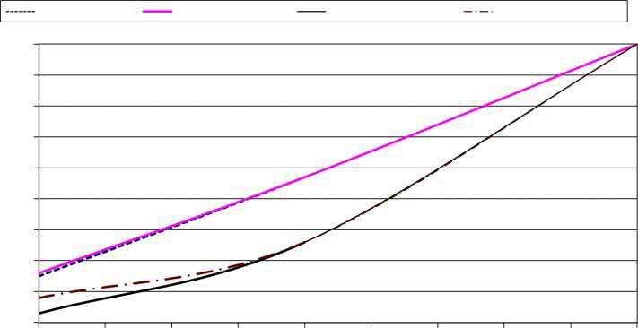
Figure1.8 VariationofHVDCstationlosseswithDCpower,shownrelativeto1p.u.losses.
constraints.Theseissuesusuallyrequirecostlylineupgrades/reconductoring,series compensationorinstallationofadevicefromtheFACTS(flexibleACtransmission systems)family.Insuchcase,conversiontoHVDCcanusuallyofferthebiggestcapacity increaseandarangeofotherbenefits.Typicallytowersandconductorswillnotbe changedbutinsulatorsmayneedtobeupgradedtooperatewithDClines.
ThemainadvantagesofconvertingexistingAClinetoHVDCare:
• anincreaseincapacity;
• fewercoronaissues,andgenerallyhigheroperatingvoltages;
• bettercontrolofactiveandreactivepower,andothersystem-levelbenefits;
• betterstabilitylimitsandactivestabilisationofthegrid;and
• lowertransmissionlosses.
SomeofthedisadvantagesofconversiontoHVDCinclude:
• morepollutionbeingattractedtoinsulatorsenergisedwithDC–insulatorupgrade isrecommended;and
• converterstationcosts.
Figure1.9showssomecommonoptionsforconvertingasingle-circuitthree-phase ACtransmissionintoDC:
1.ThefirstoptionemploysallthreeconductorsforasingleDCpolewhilegroundis usedforreturn.Thismethodwillsignificantlyincreasecurrentcarryingcapacitybut groundreturnwillnotbeallowedinmanymodernsystems.
2.ThesecondoptionsadoptsaDCbipolewithmetallicreturn.Theneutralconductor canbeusedformonopolaroperation.
3.Thethirdoptionisbasedonatri-poleHVDCconcept.Thismethodusesthethird conductoralternativelyasapositiveandnegativepole,whichexploitsthelongthermalconstantsofconductors.Acapacityincreaseofaround37%isachieved(over
Figure1.9 Optionsforconversionofthree-phase AClinesintoDC.
DC monopole with ground return
DC bipole with metalic return
DC tripole with metalic return
bipoleconfiguration)usinglinesandtheRMSvaluesofcurrentintheconductors (over10minutes)areequaltotheconductorrating.Anadditionalbidirectionalconverterisrequired.
1.7UltraHighVoltageHVDC
ThestandardDCvoltageforHVDCis500kVandtheItaipu3150MW, ±600kVHVDC hasusedthehighestDCvoltageforalongperiod.Howeverwithemergingrequirements forbulkpowertransmissionof5–10GWoverlongdistancesinAsia,AfricaandSouth Americainthelate1990sresultedintheprogressivedevelopmentofUHVDC(ultra highvoltageDC).
Xiangjiaba–Shanghai6400MW, ±800kVUHVDC,implementedin2010,wasthefirst commercialUHVDC,andfourother ±800kVsystemswereimplementedin2011–2013, whilestudiesareunderwayfor1100kVDCvoltages.TheprogresstowardsUHVDChas demandedmuchresearchanddevelopmenteffort,andthemainchallengesaresummarisedbelow:
• improvementsininsulation,inparticularinpollutedareas;
• transformerdevelopment,includingbushings;
• developmentofultrahighvoltage(UHV)testcentres.
Itisimportanttoappreciatethatalloftheequipment,includingauxiliariesthat connecttoDClines,mustbeupratedtoUHVvoltages.Inpracticethistranslatesto longerunits(bushings,arresters,voltagetransducers,currenttransducers,etc.)with moreseries-connectedbasicelements.Frequently,themainchallengebecomesthe mechanicalstrengthinthefaceofincreasedforcesfromseismicrequirements,wind andotherfactors.
Theuseofnewinsulatingmaterialsandcoronashieldsbecomesstandardtoincrease insulationlevels,althoughthedevelopmentofUHVinsulatorsandbushingsremains challenging.TheUHVvalvedesignisnotconsideredasignificantobstacle.
Thyristors
2.1OperatingCharacteristics
Thethyristorisanessentialcomponentinhighvoltagedirectcurrent(HVDC)valves anditisstilloneofthemostcommondevicesusedinpower-switchingapplicationsin allindustries.Thisisattributedtotheirhighpowerratingsandhighefficiency.Single deviceshaveupto8500V,4500Acapability,theyarebuiltonsinglewafersofupto 150mmdiameter,andhavebeeninexistenceforover60years.
Thethyristorisafour-layer,three-terminaldevice,asshowninFigure2.1.Thethree connectionsareA-anode,K-cathodeandG-gate.Whengatecurrentisapplied,thelayer betweenJ2andJ3becomesN(negative)andthethyristorbecomesaPNdevicesimilar toadiode,alsoshowninFigure2.1.Functionally,itissimilartoadiodebutthestartof conductioncanbedelayedusingthegatecircuit.
Athyristorcanbeconsideredasacontrollablediode,asshownintheoperatingcurves inFigure2.2.Withnogatecurrent, ig = 0,itbehaveslikeanopencircuit(OFFstate)in bothforwardandreversedirections.Aforwardvoltageacrossthedevice(Apositive w.r.t.K)resultsinjunctionsJ1andJ3beingforwardbiased,whereasJ2isreversebiased, andthereforeonlyasmallleakagecurrentflows.If V AK isincreasedtoacriticallimit, thedevicesuddenlyswitchestoaconductingstateastheresultofthebreakdownor breakoverofJ2.Ifagatecurrent ig isappliedthenthemagnitudeof V AK neededfor breakoverisdramaticallyreducedandthedevicebehaveslikeadiode.Thelevelof ig requiredissmallcomparedwiththemainpowercurrent.Thecurrent I l isthelatching current,whichistheanodecurrentrequiredtoensurethatthethyristorswitchesto theONstate.Onceanodecurrentreaches I l thegatecurrentcanberemoved.Thegate currentisthereforeashortpulseof10–50 μs.Theoretically,agatepulseisrequiredonce perhalf-cycle,butinpracticegatepulsesaresentmultipletimesperhalf-cycletoensure firingunderalloperatingconditions.
Oncethedeviceisconducting, ig canbereducedandthedeviceremainsintheON state.Whenthedeviceisinconduction,itsstateisdeterminedsolelybytheanode current.Iftheanodecurrent I A fallsbelowsomecriticalvalue,theholdingcurrent I h (typicallyfewamilliamps),thedeviceswitchesoff,revertingtotheblockingOFFstate. Ifareversevoltageisappliedacrossthedevice(negativeV AK ),J1andJ3become reversebiased,onlyJ2isforwardbiasedandthereforeonlyasmallleakagecurrentflows. Ifnegative V AK isincreasedsufficiently,theneventuallyavalanchebreakdownoccurs acrossJ1andJ3,resultingindamagetothedeviceunlessstepsaretakentolimitthe HighVoltageDirectCurrentTransmission:Converters,SystemsandDCGrids, SecondEdition.DraganJovcic. ©2019JohnWiley&SonsLtd.Published2019byJohnWiley&SonsLtd.