Networking Fundamentals
Crystal Panek
Copyright © 2020 by John Wiley & Sons, Inc.
Published by John Wiley & Sons, Inc.
111 River Street
Hoboken, NJ 07030 www.wiley.com
Published simultaneously in Canada
ISBN: 978-1-119-65074-4
ISBN: 978-1-119-65071-3 (ebk)
ISBN: 978-1-119-65069-0 (ebk)
Manufactured in the United States of America
No part of this publication may be reproduced, stored in a retrieval system or transmitted in any form or by any means, electronic, mechanical, photocopying, recording, scanning or otherwise, except as permitted under Sections 107 or 108 of the 1976 United States Copyright Act, without either the prior written permission of the Publisher, or authorization through payment of the appropriate per-copy fee to the Copyright Clearance Center, 222 Rosewood Drive, Danvers, MA 01923, (978) 750-8400, fax (978) 6468600. Requests to the Publisher for permission should be addressed to the Permissions Department, John Wiley & Sons, Inc., 111 River Street, Hoboken, NJ 07030, (201) 748-6011, fax (201) 748-6008, or online at http://www.wiley.com/go/permissions
Limit of Liability/Disclaimer of Warranty: The publisher and the author make no representations or warranties with respect to the accuracy or completeness of the contents of this work and specifically disclaim all warranties, including without limitation warranties of fitness for a particular purpose. No warranty may be created or extended by sales or promotional materials. The advice and strategies contained herein may not be suitable for every situation. This work is sold with the understanding that the publisher is not engaged in rendering legal, accounting, or other professional services. If professional assistance is required, the services of a competent professional person should be sought. Neither the publisher nor the author shall be liable for damages arising herefrom. The fact that an organization or Web site is referred to in this work as a citation and/or a potential source of further information does not mean that the author or the publisher endorses the information the organization or website may provide or recommendations it may make. Further, readers should be aware that Internet websites listed in this work may have changed or disappeared between when this work was written and when it is read.
For general information on our other products and services please contact our Customer Care Department within the United States at (877) 762-2974, outside the United States at (317) 572-3993 or fax (317) 5724002.
Wiley publishes in a variety of print and electronic formats and by print-on-demand. Some material included with standard print versions of this book may not be included in e-books or in print-on-demand. If this book refers to media such as a CD or DVD that is not included in the version you purchased, you may download this material at http://booksupport.wiley.com. For more information about Wiley products, visit www.wiley.com.
Library of Congress Control Number: 2019951905
Trademarks: Wiley and the Wiley logo are trademarks or registered trademarks of John Wiley & Sons, Inc. and/or its affiliates, in the United States and other countries, and may not be used without written permission. All other trademarks are the property of their respective owners. John Wiley & Sons, Inc. is not associated with any product or vendor mentioned in this book.
This book is dedicated to my loving husband, William Panek, and to my two wonderful daughters, Alexandria and Paige. Thank you all for your love and support. I love you all more than anything!
Acknowledgements
I would like to thank my husband and best friend, Will, because without him I would not be where I am today—Thank you! I would also like to express my love to my two daughters, Alexandria and Paige, who have always shown nothing but love and support. Thank you all!
I would like to thank everyone on the Sybex team, especially my Associate Acquisitions Editor, Devon Lewis, who helped make this the best book possible. I would like to thank Kathleen Wisor, who was the production editor.
Finally, I also want to thank everyone behind the scenes that helped make this book possible. Thank you all for your hard work and dedication.
About the Author
Crystal Panek holds the following certifications: MCP, MCP+I, MCSA, MCSA+ Security and Messaging, MCSE-NT (3.51 & 4.0), MCSE 2000, 2003, 2012/2012 R2, 2016, MCSE+ Security and Messaging, MCDBA, MCTS, MCITP.
For many years she trained as a contract instructor teaching at such places as MicroC, Stellacon Corporation and the University of New Hampshire. She then became the vice-president for a large IT training company and for 15 years she developed training materials and courseware to help 1000’s of students get through their certification exams. She currently works on a contract basis creating courseware for several large IT training facilities.
She currently resides in New Hampshire with her husband and two daughters. In her spare time, she likes to camp, hike, shoot trap and skeet, golf, bowl, and snowmobile.
What Does This Book Cover?
Chapter 1: Understanding Local Area Networking This chapter covers understanding local area networks (LANs), perimeter networks, addressing, reserved address ranges for local use (including local loopback IP), VLANs, wired LAN and wireless LAN. Discusses understanding network topologies and access methods. Discusses star, mesh, ring, bus, logical and physical topologies as well as a brief overview of using switches.
Chapter 2: Defining Networks with the OSI Model This chapter covers understanding the Open Systems Interconnection (OSI) model. Discusses the Transmission Control Protocol (TCP) model, examples of devices, protocols, applications, and which OSI/TCP layer they belong to. This chapter also discusses TCP and User Datagram Protocol (UDP), wellknown ports and their purposes, as well as discussing packets and frames. This chapter also discusses switches, transmission speed, number and type of ports, number of uplinks, speed of uplinks, managed or unmanaged switches, VLAN capabilities, Layer 2 and Layer 3 switches and security options, hardware redundancy, support, backplane speed, switching types and MAC table. As well as the capabilities of hubs versus switches and virtual switches.
Chapter 3: Understanding Wired and Wireless Networks This chapter covers understanding different media types, cable types and their characteristics, including media segment length and speed, fiber optic, twisted pair shielded or unshielded, catxx cabling, wireless, susceptibility to external interference (machinery and power cables), susceptibility to electricity (lightning), and susceptibility to interception. This chapter also provides a brief discussion on local area networks (LANs). VLANs, wired LAN and wireless LAN. This chapter discusses wireless networking including types of wireless networking standards and their characteristics, the 802.11a,b,g,n,ac including different GHz ranges, types of network security (WPA, WEP, 802.1X, and others), point-to-point (P2P) wireless, ad hoc networks, and wireless bridging.
Chapter 4: Understanding Internet Protocol This chapter covers understanding Local Area Networks (LANs), using reserved address ranges for local use (including the local loopback IP). This chapter discusses understanding IPv4 and IPv6, including subnetting, IPconfig, why use Internet Protocol version 4 (IPv4), why use Internet Protocol version 6 (IPv6) addressing, ipv4toipv6 tunneling protocols to ensure backward compatibility, dual IP stack, subnetmask, gateway, ports, and packets.
Chapter 5: Implementing TCP/IP in the Command Line This chapter covers understanding TCP/IP tools such as ping, tracert, pathping, Telnet, IPconfig, netstat, reserved address ranges for local use (including local loopback IP), protocols as well as discussing using a routers routing table memory.
Chapter 6: Working with Networking Services This chapter covers a brief discussion on understanding wireless networking, understanding names resolution, DNS, resource records, Windows Internet Name Service (WINS), the name resolution process, HOSTS file and the LMHOSTS file. This chapter also discusses understanding networking services including Dynamic Host Configuration Protocol (DHCP), Network Address Translation (NAT), firewalls, remote access and VPNs.
Chapter 7: Understanding Wide Area Networks This chapter covers understanding routers and directly connected routes, static routing, dynamic routing (routing protocols), RIP vs. OSPF, default routes; routing table and how it selects best route(s). Also covers installing and configuring routing and Quality of Service (QoS). This chapter also discusses understanding wide area networks (WANs), leased lines, dial-up, ISDN, VPN, T1, T3, E1, E3, DSL, cable modems and their characteristics (speed, availability).
Chapter 8: Defining Network Infrastructures and Network Security This chapter covers understanding the concepts of Internet, intranet, and extranet as well as Virtual Private Networks (VPNs), security zones and firewalls.
Local Area
Networks, Devices, and Data Transfer
Simply stated, a network is two or more computers that exchange data. A local area network (LAN) is a group of these computers that are confined to a small geographic area, usually one building. Setting up a LAN requires computers with network adapters, central connecting devices to connect those computers together, and a numbering scheme (such as IP addresses) to differentiate one computer from the next. It can also include servers, some type of protective device such as a firewall, and connections to perimeter networks that are adjacent to the LAN.
Defining the LAN
As mentioned, a LAN requires computers with network adapters, central connecting devices, and some type of medium to tie it altogether, be it cabled or wireless connections. These must be connected together in some way to facilitate the transfer of data. It is important to define how they are connected together, as well as how they actually transmit data.
Certification Ready
What is a local area network (LAN)? Objective 1.2
We mentioned that a network is used to exchange data. But what are the real reasons that an organization will desire (or need) a network? They can be organized into four categories:
Sharing The sharing of files, databases, and media
Communication The methods of communication, such as email, instant messaging, and faxing
Organization The ability to centralize data and make it more accessible and efficient
$$$ The ability for the network to provide cost savings and/or increase productivity
Some would place security in this list of categories, but, unfortunately, as you will find, many networks, devices, and operating systems are insecure when they are fresh out of the box. Just having a network doesn’t ensure security. In fact, many steps must be taken to implement a secure network.
To understand local area networks (LANs) better, it helps to write out the structure of the LAN—to document it. Network documentation is any information that helps describe, define, and otherwise explain how computers are connected in a physical and logical way. For example, the physical connection could be cables, and the logical connection could be the various IP addresses used by the devices on the network.
In the following exercises, you will:
Examine typical LAN network documentation.
View the type of network adapter in a computer, inspect the type of connection that the network adapter makes to the network, and view its Properties page.
Define how information is sent across the LAN.
Configure IP addresses on hosts.
The ability to document networks is an important skill for network administrators. The documentation phase occurs before networks are built and whenever changes or additions are made to the network. Microsoft Visio is a common tool used for network documentation; Figures 1.1 to 1.3 were developed using Visio.
Examine LAN Network Documentation
To examine LAN network documentation, perform the following steps.
Download
You can download a free trial of Visio from the Microsoft website. A link is provided on the companion website.
Certification Ready
What are the capabilities of hubs as compared to switches? Objective 2.1
1. Examine Figure 1.1, which shows a basic example of a LAN.
FigURe 1.1 Basic LAN documentation
Today, a hub is considered a legacy hardware device that is largely obsolete. Hubs have been replaced by network switches, which are discussed later in this section and can be found in very old installations or specialized applications.
You will notice that in the center of the diagram is a hub, also known as a multiport repeater. This is the most basic of central connecting devices (CCDs); it connects each of the computers, known as hosts, to each other by way of copper-based cables. When a host needs to send data, it fi rst sends that data to the hub, where it is amplified and broadcast to the rest of the network. Broadcasting means that the data is sent out to every host on the network. Of course, only the intended recipient keeps the data; the rest of the hosts discard it. Although this is a bit wasteful, it was the standard for a long time. Today, however, switching technology, which is more effi cient, is the standard. You’ll learn more about switching technology later in this lesson. In the figure, several hosts connect to the hub, including:
A server, used to centralize data and share it with (or serve it to) other computers on the network.
A PC (personal computer) usually acts as a client on the network, most likely getting its information from the server. The PC can also store information locally.
A Mac (Macintosh) computer, which is another type of client computer; once again, this computer can store information locally, or get it from the server.
A laptop, which could be a PC or a Mac, is meant for portability. However, it can also store and access data the same way the other computers do.
Laptop Mac
2. Examine your own network and record your results. Use Visio, if possible; otherwise, draw out your own network documentation on paper. Whether you are at home or at a school or business, chances are that you are connected to a LAN. Try to identify any hosts on the network (PCs, laptops, servers, etc.). Then, identify the central connecting device that ties everything together. This could be a basic hub, a switch, or a router or multifunction network device.
If you are using Microsoft Visio, utilize the Basic Network Diagram template. This can be accessed in the Network section when starting a new document.
3. Examine Figure 1.2 . This is an intermediate example of a LAN.
1.2 Intermediate LAN documentation
In Figure 1.2 , the hub is replaced with a basic four-port router; these are also referred to as SOHO (Small Offi ce/Home Offi ce) routers. The router acts as a central connecting device, connecting the hosts together, but also has a special communications link to the Internet, allowing the hosts to send and receive data to and from computers on the Internet. That communications link between the router and the Internet is where the LAN ends. So, the PC, laptop, server, and router are part of the LAN. Anything else beyond the router is considered to be outside of the LAN.
4. Examine your own LAN again. If possible, identify any routers and connections to the Internet (or other networks). Add these to your written, or Visio, documentation.
5. Examine Figure 1.3. This is a slightly more advanced example of a LAN.
FigURe
In Figure 1.3, more central connecting devices are added. Instead of connecting hundreds of devices to a single central connecting device, you can break up the network in a hierarchical fashion. For example, on the left side of the figure are two PCs and one server connected to a hub. Let’s say that these represent 24 computers, and that each other group of computers connected to a hub also represents 24 computers. Instead of connecting all the computers to a single, central connecting device, which might not be able to physically support all of the hosts, the groups of 24 hosts are connected to their own hub. Then, the hubs are all daisy-chained to a switch at the top of the figure. The switch will most likely be a powerful (and expensive) device, in order to support all of the computers that ultimately connect to it. You can regard the individual hubs as devices that allow connectivity for single departments in a company, or individual classrooms in a school. The master switch at the top of the hierarchical tree connects everything together; however, it also acts as a single point of failure, which is addressed in Lesson 2. As you can guess, this type of network architecture is the kind we will need to use to accomplish the goals laid out in the scenario at the beginning of this lesson.
The network adapter, also known as a network interface card (NIC), is the device that enables the sending and receiving of data to and from your computer. It might be integrated into the motherboard or it might act as a separate device that connects to a PCI slot, or perhaps connects to a PC Card slot or USB port. It connects to the network by way of cable (wired) or by air (wireless). It has its own basic CPU to process transmitted data and a ROM chip to store information about itself. Network adapters also have a software component known as a driver, defining how the card will interact with the operating system; this usually includes a Properties page that can be accessed in the operating system, enabling the user to configure the adapter as he sees fit.
View the Network Adapter
To view the network adapter, perform the following steps.
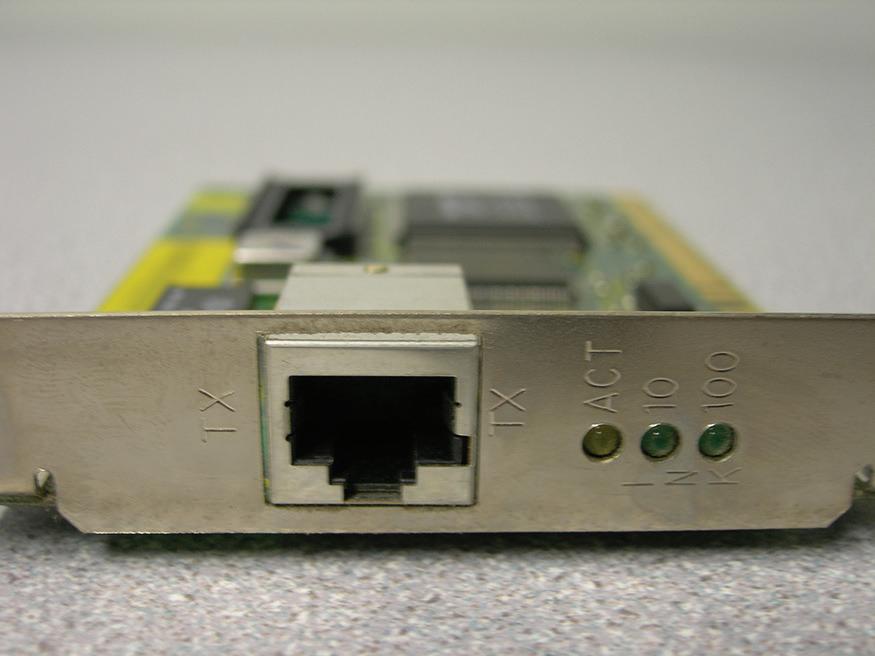
1. Examine Figure 1.4, which shows a typical network adapter.
This particular network adapter is a PCI card, but again, network adapters come in many different forms. However, notice the port on the card. This is known as an RJ-45 port, and is where the RJ-45 plug at the end of the network cable connects. This is the most common type of network adapter port, allowing the adapter to connect to most of today’s wired networks.
2. Look for the network adapter on your computer. If the computer only uses a wireless network adapter, look for an antenna on the card. Laptops have an internal antenna, but you can usually find out if you are connected wirelessly by looking at the wireless LED.
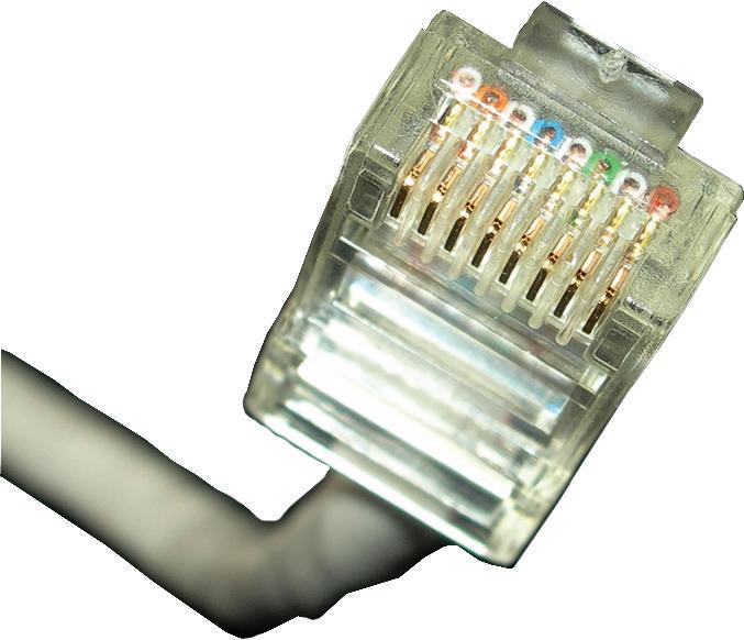
3. Examine Figure 1.5. This is a typical patch cable that connects to an RJ-45 port.
Fig UR e 1.4 Photo of a typical network adapter
Fig UR e 1.5 Photo of a typical patch cable
This type of cable is known as twisted pair. It has an RJ-45 plug on the end, which is molded so it can only connect one way to the RJ-45 port. It also has a tab that locks it in place. The RJ-45 plug is slightly larger than a telephone cable’s RJ-11 plug, but looks very similar. Another difference is that the phone plug usually has four wires, whereas the RJ-45 plug has eight.
4. Identify the cable that connects your computer to the network. Disconnect the cable (finish any downloads from the Internet if in progress first) and view the connector. If you are connected via a cable, attempt to identify what device is connected to the other end of the cable, such as a hub, switch, or router.
5. Now let’s access the operating system and look at the properties of a network adapter. For this example, we are using a Windows 10 client computer with a Realtek PCIe network adapter. However, older versions of Windows have almost identical window and dialog box names, and the navigation to those windows is similar as well.
a. Right-click Start and choose Computer Management. Alternatively for Windows 10, and for Windows Server 2016, click Start, type Computer Management , and then press Enter.
b. Click Device Manager.
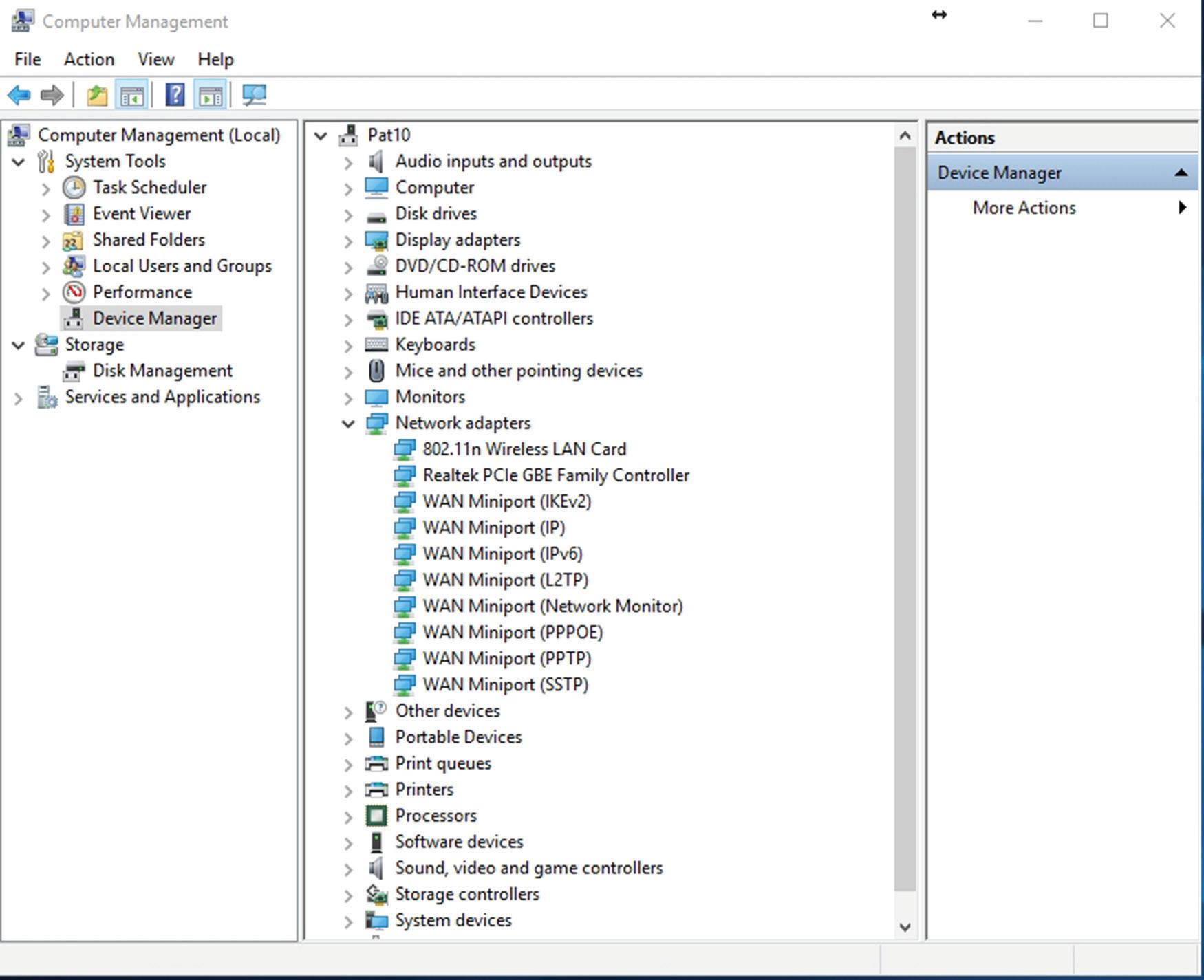
c. Click the > sign to expand the Network adapters category, as shown in Figure 1.6.
Fig UR e 1.6 Device Manager with the Network adapters category expanded
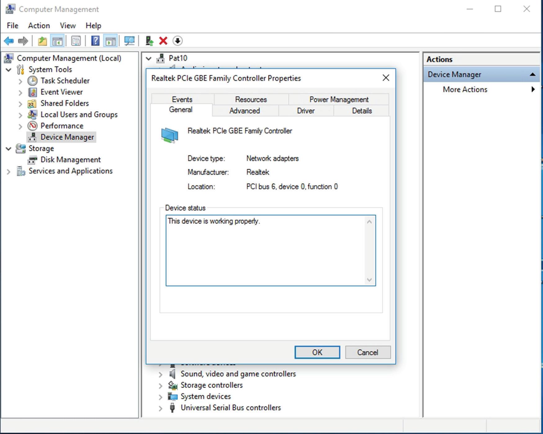
d. Right-click the network adapter and choose Properties. A dialog box similar to the one shown in Figure 1.7 opens.
FigURe 1.7 Properties dialog box of a Realtec network adapter
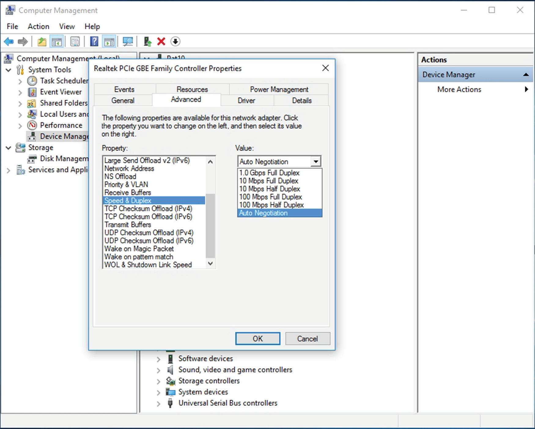
6. Click the Advanced tab. If you click the Speed & Duplex option, you can then change the value, as shown in Figure 1.8. A network adapter is only as fast as the network it connects to!
Full-duplex means that the network card can send and receive data simultaneously. In the Speed and Duplex drop-down menu, you can select various speeds , including 10 Mbps, 100 Mbps, and 1 Gbps. You can also select half-duplex, which means that the network adapter can send and receive data, but not at the same time. Full-duplex is the superior connection, as long as your central connecting device supports it. A fullduplex connection can transceive (transmit and receive) twice as much information per second compared with a half-duplex connection. So, to meet the requirements of the original scenario, you would probably want your client computers to connect at 1 Gbps as well as utilize full-duplex negotiations.
You can tell that a card is active because the Link Status field on the physical device shows a green light. You can also open the device Status window (Open Network and Sharing Center, and clink the adapter link) to see the current speed of the adapter such as 1 Gbps, its media state, how long it has been up and the current activity.
Fig UR e 1.8 Link speed of the network adapter
7. Finally, every network adapter will have a logical name. By default, the network adapter is known as Ethernet, although you can change the name if you so desire. Ethernet will have its own Properties page and a status page. Let’s view these now:
a. Right-click the Network icon on the far right of the taskbar and choose Open Network And Sharing Center. The Network And Sharing Center window opens.. An alternate way to access the Network and Sharing Center is to right-click Start and choose Control Panel. Then, navigate to Network And Internet ➢ Network And Sharing Center.
b. Click the Change Adapter Settings link. The Network Connections window opens. (Navigation to this window is slightly different in other versions of Windows.)
c. In this window, right-click the Ethernet icon and choose Properties. The Ethernet Properties dialog box opens, as shown in Figure 1.9.
Fig UR e 1.9 The Ethernet Properties dialog box
From here, you can configure Internet Protocol (IP), bind new protocols to the network adapter, and so on. You’ll access this dialog box frequently during the course of this book.
d. Click Cancel to close the dialog box. This should return you to the Network Connections window.
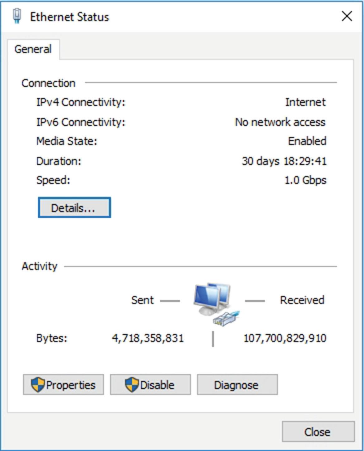
e. Now, double-click the Ethernet icon. The Ethernet Status dialog box opens, as shown in Figure 1.10. This dialog box displays the type of connectivity, speed, and how long the adapter has been connected; it also shows the total bytes sent and received. In addition, from this dialog box, you can access the Properties dialog box and diagnose the network adapter, if necessary.
Defining Data Transfer on the LAN
Generally, when data is transferred on the LAN, it is sent in a serial fashion over twisted-pair cabling. Serial data transfer means the transfer of one bit at a time—a single bit stream. This is usually the format in which information is sent from one network
Fig UR e 1.10 The Ethernet Status dialog box
adapter to another. Let’s discuss this in a little more depth. Suppose one user wants to send a small text file (100 bytes in size) to another user on the network. There are many ways to do this; one way is to map a network drive to the other user’s computer and simply copy and paste the text file to the other computer’s hard drive. When this is done, a few things happen:
1. First, the text file is packaged by the operating system into what is known as a packet. This packet is slightly larger than the original file. That packet is then sent to the network adapter.
2. Next, the network adapter takes that packet and places it inside of a frame, which is slightly larger than a packet. Usually, this is an Ethernet frame.
3. Now, the frame of information needs to be sent on to the physical media—the cabling. To do this, the network adapter breaks down the frame of information into a serial bit stream to be sent one bit at a time across the cables to the other computer.
4. The receiving computer takes the serial bit stream and re-creates the frame of data. After analyzing the frame and verifying that it is indeed the intended recipient, it strips the frame information so that only the packet remains.
5. The packet is sent to the operating system, and, ultimately, the text file shows up on the computer’s hard drive, available to the other user through Windows Explorer. This is a very basic example of data transfer, which is expanded on in Lesson 2.
Usually, local area networks utilize one of several Ethernet standards. Ethernet is a set of rules that govern the transmission of data between network adapters and various central connecting devices. All network adapters and central connecting devices must be compatible with Ethernet in order to communicate with each other. A very common type of Ethernet is known as 802.3u or Fast Ethernet that runs at 100 Mbps. Another common one is 802.3ab or Gigabit Ethernet.
In this type of network, when a computer wants to send data, that data is broadcast to every other host on the network by default. The problem with this is that usually there is only one recipient of the data. The rest of the computers simply drop the data packets. This, in turn, wastes network bandwidth. To alleviate this, about 15 years ago, Ethernet switching was developed, and it is used in most networks today. Switching has many advantages, one of which is that the switch only sends unicast traffic. Unicast is when information is sent to one host only. This reduces network traffic greatly, and helps with packet loss and duplicates.
We have mentioned network speed a few times already. A more accurate term is data transfer rate, otherwise known as bit rate. This is defined as the maximum bits per second (bps) that can be transmitted over the network. As mentioned, it is rated in bits and is signified with a lowercase b, for example, 10 Mbps. The lowercase b helps to differentiate from data that is stored on a hard drive, which uses an uppercase B that stands for bytes, for example 10 MB.
Of course, all this means nothing without an addressing system in place. The most common type of network address is the Internet Protocol address, or IP address.