ElectrocatalysisforMembraneFuelCells
Methods,Modeling,andApplications
EditedbyNicolasAlonso-VanteandVitoDiNoto
Editors
Prof.NicolasAlonso-Vante UniversityofPoitiers IC2MP-UMR-CNRS7285 4rueMichelBrunet F-86073PoitiersCedex9 France
Prof.VitoDiNoto UniversityofPadova DepartmentofIndustrialEngineering ViaMarzolo9 I-35131Padova Italy
CoverImage: CourtesyofVitoDiNoto, NicolasAlonsoVanteandKetiVezzù
Allbookspublishedby WILEY-VCH arecarefully produced.Nevertheless,authors,editors,and publisherdonotwarranttheinformation containedinthesebooks,includingthisbook, tobefreeoferrors.Readersareadvisedtokeep inmindthatstatements,data,illustrations, proceduraldetailsorotheritemsmay inadvertentlybeinaccurate.
LibraryofCongressCardNo.: appliedfor BritishLibraryCataloguing-in-PublicationData Acataloguerecordforthisbookisavailable fromtheBritishLibrary.
Bibliographicinformationpublishedby theDeutscheNationalbibliothek TheDeutscheNationalbibliotheklists thispublicationintheDeutsche Nationalbibliografie;detailedbibliographic dataareavailableontheInternetat <http://dnb.d-nb.de>
©2024WILEY-VCHGmbH,Boschstraße12, 69469Weinheim,Germany
Allrightsreserved(includingthoseof translationintootherlanguages).Nopartof thisbookmaybereproducedinanyform–by photoprinting,microfilm,oranyothermeans–nortransmittedortranslatedintoamachine languagewithoutwrittenpermissionfromthe publishers.Registerednames,trademarks,etc. usedinthisbook,evenwhennotspecifically markedassuch,arenottobeconsidered unprotectedbylaw.
PrintISBN: 978-3-527-34837-4
ePDFISBN: 978-3-527-83055-8
ePubISBN: 978-3-527-83056-5
oBookISBN: 978-3-527-83057-2
Typesetting: Straive,Chennai,India
Preface xv
PartIOverviewofSystems 1
1System-levelConstraintsonFuelCellMaterialsand Electrocatalysts 3
ElliotPadgettandDimitriosPapageorgopoulos
1.1OverviewofFuelCellApplicationsandSystemDesigns 3
1.1.1System-levelFuelCellMetrics 3
1.1.2FuelCellSubsystemsandBalanceofPlant(BOP)Components 5
1.1.3ComparisonofFuelCellSystemsforDifferentApplications 9
1.2Application-derivedRequirementsandConstraints 10
1.2.1FuelCellPerformanceandtheHeatRejectionConstraint 10
1.2.2Startup,Flexibility,andRobustness 13
1.2.3FuelCellDurability 14
1.2.4Cost 16
1.3MaterialPathwaystoImprovedFuelCells 18
1.4Note 19
Acronyms 20 Symbols 20 References 20
2PEMFuelCellDesignfromtheAtomtotheAutomobile 23
AndrewHaugandMichaelYandrasits
2.1Introduction 23
2.2ThePEMFCCatalyst 27
2.3TheElectrode 32
2.4Membrane 38
2.5TheGDL 42
2.6CCMandMEA 46
2.7FlowfieldandSingleFuelCell 50
2.8StackandSystem 55
Acronyms 57 References 58
PartIIBasics–Fundamentals 69
3ElectrochemicalFundamentals 71
VitoDiNoto,GioelePagot,KetiVezzù,EnricoNegro,andPaoloSgarbossa
3.1PrinciplesofElectrochemistry 71
3.2TheRoleoftheFirstFaradayLaw 71
3.3ElectricDoubleLayerandtheFormationofaPotentialDifferenceatthe Interface 73
3.4TheCell 74
3.5TheSpontaneousProcessesandtheNernstEquation 75
3.6RepresentationofanElectrochemicalCellandtheNernst Equation 77
3.7TheElectrochemicalSeries 79
3.8Dependenceofthe Ecell onTemperatureandPressure 82
3.9ThermodynamicEfficiencies 83
3.10CaseStudy–TheImpactofThermodynamicsontheCorrosionofLow-T FCElectrodes 85
3.11ReactionKineticsandFuelCells 88
3.11.1CorrelationBetweenCurrentandReactionKinetics 88
3.11.2TheConceptofExchangeCurrent 89
3.12ChargeTransferTheoryBasedonDistributionofEnergyStates 89
3.12.1TheButler–VolmerEquation 96
3.12.2TheTafelEquation 100
3.12.3InterplayBetweenExchangeCurrentandElectrocatalystActivity 101
3.13Conclusions 103
Acronyms 104 Symbols 104 References 107
4QuantifyingtheKineticParametersofFuelCell Reactions 111
ViktoriiaA.Saveleva,JuanHerranz,andThomasJ.Schmidt
4.1Introduction 111
4.2ElectrochemicalActiveSurfaceArea(ECSA)Determination 114
4.2.1ECSADeterminationUsingUnderpotentialDeposition 115
4.2.1.1HydrogenUnderpotentialDeposition(HUPD ) 116
4.2.1.2CopperUnderpotentialDeposition(CuUPD ) 117
4.2.2ECSAQuantificationBasedontheAdsorptionofProbeMolecules 118
4.2.2.1COStripping 118
4.2.2.2NO2 ∕NOSorption 119
4.2.3Double-layerCapacitanceMeasurementsandOtherMethods 120
4.2.4ECSAMeasurementsinaPEFC:WhichMethodtoChoose? 120
4.3H2 -OxidationandElectrochemicalSetupsfortheQuantificationof KineticParameters 121
4.3.1RotatingDiscElectrodes(RDEs) 122
4.3.2HydrogenPump(PEFC)Approach 124
4.3.3UltramicroelectrodeApproach 125
4.3.4ScanningElectrochemicalMicroscopy(SECM)Approach 125
4.3.5FloatingElectrodeMethod 127
4.3.6MethodsSummary 128
4.4ORRKinetics 129
4.4.1ORRMechanismStudieswithRRDESetups 129
4.4.2ORRPathwayonMe/N/CORRCatalysts 130
4.4.3ORRKinetics:Methods 132
4.4.3.1Pt-basedElectrodes 132
4.4.3.2Pt-freeCatalysts:RDEvs.PEFCKineticStudies 133
4.5ConcludingRemarks 133 Acronyms 134 Symbols 134 References 135
5AdverseandBeneficialFunctionsofSurfaceLayersFormed onFuelCellElectrocatalysts 149 ShimshonGottesfeld
5.1Introduction 149
5.2CatalystCappinginHeterogeneousCatalysisandin Electrocatalysis 151
5.3PassivationofPGM/TMandNon-PGMHORCatalystsandItsPossible Prevention 156
5.4LiteratureReportsonFuelCellCatalystProtectionbyCapping 161
5.4.1ProtectionofORRPtcatalystsAgainstAgglomerationbyanUltrathin OverlayerofMesoporousSiO2 orMe–SiO2 161
5.4.2ProtectionbyCarbonCapsAgainstCatalystDetachmentandCatalyst PassivationUnderAmbientConditions 162
5.5OtherMeansforImprovingthePerformanceStabilityofSupported Electrocatalysts 166
5.5.1ReplacementofCarbonSupportsbyCeramicSupports 166
5.5.2ProtectionofPtCatalystsbyEnclosureinMesopores 167
5.6Conclusions 170 Abbreviations 171 References 171
PartIIIStateoftheArt 175
6DesignofPGM-freeORRCatalysts:FromMoleculartothe StateoftheArt 177
NaomiLevyandLiorElbaz
6.1Introduction 177
6.2TheInfluenceofMolecularChangesWithintheComplex 179
6.2.1TheRoleoftheMetalCenter 179
6.2.2AdditionofSubstituentstoMCs 183
6.2.2.1Beta-substituents 184
6.2.3Meso-substituents 186
6.2.4AxialLigands 187
6.3CooperativeEffectsBetweenNeighboringMCs 190
6.3.1BimetallicCofacialComplexes–“Packman”Complexes 191
6.3.2MCPolymers 191
6.4ThePhysicaland/orChemicalInteractionsBetweentheCatalystandIts SupportMaterial 193
6.5EffectofPyrolysis 194
Acronyms 196 References 196
7RecentAdvancesinElectrocatalystsforHydrogenOxidation ReactioninAlkalineElectrolytes 205 IndraN.PulidindiandMeitalShviro
7.1Introduction 205
7.2MechanismoftheHORinAlkalineMedia 206
7.3ElectrocatalystsforAlkalineHOR 212
7.3.1PlatinumGroupMetalHORElectrocatalysts 212
7.3.2Non-platinumGroupMetal-basedHORElectrocatalysts 214
7.4Conclusions 220 Acronyms 221 References 221
8MembranesforFuelCells 227
PaoloSgarbossa,GiovanniCrivellaro,FrancescoLanero,GioelePagot, AfaafR.Alvi,EnricoNegro,KetiVezzù,andVitoDiNoto
8.1Introduction 227
8.2PropertiesofthePEseparators 228
8.2.1BenchmarkingofIEMs 229
8.2.2Ion-exchangeCapacity(IEC) 229
8.2.3WaterUptake(WU),SwellingRatio(SR),andWaterTransport 231
8.2.4IonicConductivity(�� ) 233
8.2.5GasPermeability 234
8.2.6ChemicalStability 235
8.2.7ThermalandMechanicalStability 237
8.2.8CostoftheIEMs 239
8.3ClassificationofIon-exchangeMembranes 240
8.3.1Cation-exchangeMembranes(CEMs) 240
8.3.1.1PerfluorinatedMembranes 240
8.3.1.2NonperfluorinatedMembranes 245
8.3.2Anion-exchangeMembranes(AEMs) 246
8.3.2.1FunctionalizedPolyketones 247
8.3.2.2Poly(VinylBenzylTrimethylAmmonium)(PVBTMA)Polymers 248
8.3.2.3Poly(sulfones)(PS) 249
8.3.3HybridIon-exchangeMembranes 249
8.3.3.1HybridMembraneswithSingleCeramicOxoclusters[P/(Mx Oy )n ] 250
8.3.3.2HybridMembranesComprisingSurface-functionalizedNanofillers 254
8.3.3.3HybridMembranesDopedwithhierarchical “Core–Shell” Nanofillers 254
8.3.4PorousMembranes 257
8.3.4.1PorousMembranesasHostMaterial 257
8.3.4.2PorousMembranesasSupportLayer 258
8.3.4.3PorousMembranesasUnconventionalSeparators 259
8.4MechanismofIonConduction 259
8.5SummaryandPerspectives 268
Acronyms 271 Symbols 272 References 272
9SupportsforOxygenReductionCatalysts:Understandingand ImprovingStructure,Stability,andActivity 287 IwonaA.Rutkowska,SylwiaZoladek,andPawelJ.Kulesza
9.1Introduction 287
9.2CarbonBlackSupports 288
9.3DecorationandModificationwithMetalOxideNanostructures 289
9.4CarbonNanotubeasCarriers 291
9.5Doping,Modification,andOtherCarbonSupports 293
9.6GrapheneasCatalyticComponent 293
9.7MetalOxide-containingORRCatalysts 296
9.8PhotodepositionofPtonVariousOxide–CarbonComposites 299
9.9OtherSupports 301
9.10AlkalineMedium 302
9.11TowardMoreComplexHybridSystems 303
9.12StabilizationApproaches 306
9.13ConclusionsandPerspectives 307
Acknowledgment 308
Acronyms 308 References 308
Contents
PartIVPhysical–ChemicalCharacterization 319
10UnderstandingtheElectrocatalyticReactionintheFuelCell byTrackingtheDynamicsoftheCatalystbyX-rayAbsorption Spectroscopy 321
DittyDixon,AiswaryaBhaskar,andAswathiThottungal
10.1Introduction 321
10.2AShortIntroductiontoXAS 323
10.3ApplicationofXASinElectrocatalysis 325
10.3.1 ExSitu CharacterizationofElectrocatalyst 325
10.3.2 Operando XASStudies 330
10.4 �� XANESAnalysistoTrackAdsorbate 334
10.5Time-resolved Operando XASMeasurementsinFuelCells 338
10.6Fourth-generationSynchrotronFacilitiesandAdvanced CharacterizationTechniques 340
10.6.1Total-reflectionFluorescenceX-rayAbsorptionSpectroscopy 341
10.6.2ResonantX-rayEmissionSpectroscopy(RXES) 341
10.6.3CombinedXRDandXAS 342
10.7Conclusions 342
Acronyms 343 References 344
PartVModeling 349
11UnravelingLocalElectrocatalyticConditionswithTheoryand Computation 351
JunHuang,MohammadJ.Eslamibidgoli,andMichaelH.Eikerling
11.1LocalReactionConditions:WhyBother? 351
11.2FromElectrochemicalCellstoInterfaces:BasicConcepts 352
11.3CharacteristicsofElectrocatalyticInterfaces 355
11.4MultifacetedEffectsofSurfaceChargingontheLocalReaction Conditions 356
11.5TheChallengesinModelingElectrifiedInterfacesusingFirst-principles Methods 358
11.5.1ComputationalHydrogenElectrode 359
11.5.2Unit-cellExtrapolation,ExplicitSolvatedProtons,andExcess Electrons 360
11.5.3CounterChargeandReferenceElectrode 361
11.5.4EffectiveScreeningMediumandmPBTheory 361
11.5.5Grand-canonicalDFT 362
11.6AConcertedTheoretical–ComputationalFramework 362
11.7CaseStudy:OxygenReductionatPt(111) 364
11.8Outlook 367 Acronyms 367 Symbols 368 References 368 PartVIProtocols 375
12QuantifyingtheActivityofElectrocatalysts 377 KarlaVega-GranadosandNicolasAlonso-Vante
12.1Introduction:TowardaSystematicProtocolforActivity Measurements 377
12.2MaterialsConsideration 378
12.2.1PGMGroup 378
12.2.2LowPGMandPGM-freeApproaches 379
12.2.3ImpactofSupportEffectsonCatalyticSites 381
12.3ElectrochemicalCellConsiderations 382
12.3.1CellConfigurationandMaterial 382
12.3.2Electrolyte 385
12.3.2.1Purity 385
12.3.2.2Protonsvs.HydroxideIons 386
12.3.2.3InfluenceofCounterions 388
12.3.3ElectrodePotentialMeasurements 388
12.3.4PreparationofElectrodes 391
12.3.5Well-definedandNanoparticulatedObjects 395
12.4ParametersDiagnosticofElectrochemicalPerformance 396
12.4.1SurfaceArea 396
12.4.2HydrogenUnderpotentialDepositionIntegration 397
12.4.2.1SurfaceOxideReduction 398
12.4.2.2COMonolayerOxidation(COStripping) 400
12.4.2.3UnderpotentialDepositionofMetals 401
12.4.2.4Double-layerCapacitance 402
12.4.3ElectrocatalystsSiteDensity 402
12.4.4DataEvaluation(Half-CellReactions) 404
12.4.5The E1/2 and E ( jPt (5%))Parameters 405
12.5StabilityTests 407
12.6DataEvaluation(AuxiliaryTechniques) 409
12.6.1SurfaceAtomsvs.Bulk 410
12.7Conclusions 411 Acknowledgments 412 Acronyms 412 Symbols 413 References 414
13DurabilityofFuelCellElectrocatalystsandMethodsfor PerformanceAssessment 429 BiancaM.CeballosandPiotrZelenay
13.1Introduction 429
13.2FuelCellPGM-freeElectrocatalystsforLow-temperature Applications 431
13.3PGM-freeElectrocatalystDegradationPathways 432
13.3.1Demetallation 432
13.3.2CarbonOxidation 436
13.3.3MicroporeFlooding 439
13.3.4NitrogenProtonationandAnionicAdsorption 439
13.4PGM-freeElectrocatalystDurabilityandMetrics 440
13.4.1PerformanceandDurabilityEvaluationinAir-suppliedFuelCell Cathode 440
13.4.2AssessmentofCarbonCorrosioninNitrogen-purgedCathode 443
13.4.3DeterminationofPerformanceLossuponCyclingCathodeCatalystin Nitrogen 443
13.4.4RecommendationsforORRElectrocatalystEvaluationinRRDEinO2 andinanInertGas 446
13.4.5ElectrocatalystCorrosion 447
13.5Low-PGMCatalystDegradation 447
13.5.1PtDissolution 449
13.5.2CarbonSupportCorrosion 452
13.5.3PtCatalystMEAActivityAssessmentandDurability 454
13.5.4PGMElectrocatalystMEAConditioninginH2 /Air 454
13.5.5AcceleratedStressTestofPGMElectrocatalystDurability 456
13.6Conclusion 457 Acronyms 459 References 460
PartVIISystems 471
14ModelingofPolymerElectrolyteMembraneFuelCells 473
AndreaBaricci,AndreaCasalegno,DarioMaggiolo,FedericoMoro, MatteoZago,andMassimoGuarnieri
14.1Introduction 473
14.2GeneralEquationsforPEMFCModels 474
14.2.1AnalyticalandNumericalModeling 474
14.2.2ReversibleElectromotiveForce 476
14.2.3FuelCellVoltage 477
14.2.4ActivationOverpotential 478
14.2.5OhmicOverpotential–PEMModel 479
14.2.6ConcentrationOverpotential 480
14.2.7ExamplesofFuelCellModeling 482
14.3MultiphaseWaterTransportModelforPEMFCs 483
14.4FluidMechanicsinPEMFCPorousMedia:From3DSimulationsto1D Models 488
14.4.1FromMicro-toMacroscopicModels 490
14.4.2PorousMediumAnisotropy 491
14.4.3Fluid–FluidViscousDrag 492
14.4.4SurfaceTensionandCapillaryPressure 492
14.5Physical-basedModelingforElectrochemicalImpedance Spectroscopy 496
14.5.1ExperimentalMeasurementandModelingApproaches 496
14.5.2Physical-basedModeling 497
14.5.2.1CurrentRelaxation 497
14.5.2.2LaplaceTransform 498
14.5.3TypicalImpedanceFeaturesofPEMFC 498
14.5.4ApplicationofEISModelingtoPEMFCDiagnostic 500
14.5.5Approximationsof1DApproach 501
14.6ConclusionsandPerspectives 502 Acronyms 503 Symbols 504 References 507
15Physics-basedModelingofPolymerElectrolyteMembrane FuelCells:FromCelltoAutomotiveSystems 511 AndreaBaricci,MatteoZago,SimoneBuso,MarcoSorrentino,and AndreaCasalegno
15.1PolymerFuelCellModelforStackSimulation 511
15.1.1GeneralCharacteristicsofaFuelCellSystemforAutomotive Applications 511
15.1.2AnalysisoftheChannelGeometryforStackPerformanceModeling 514
15.1.3AnalysisoftheAirandHydrogenUtilizationforStackPerformance Modeling 516
15.1.4IntroductiontoTransientStackModels 518
15.2AuxiliarySubsystemsModeling 519
15.2.1AirManagementSubsystem 519
15.2.2HydrogenManagementSubsystem 521
15.2.3ThermalManagementSubsystem 522
15.2.4PEMFCSystemSimulation 522
15.3ElectronicPowerConvertersforFuelCell-poweredVehicles 525
15.3.1PowerConverterArchitecture 527
15.3.2LoadAdaptability 527
15.3.3PowerElectronicSystemComponents 528
15.3.3.1PortInterfaceConverters 530
15.3.3.2ThePEMFCInterfaceConverter 530
15.3.3.3TheMotorInterfaceConverter 530
15.3.3.4TheEnergyStorageInterface 531
15.3.3.5SupervisoryControl 531
15.4FuelCellPowertrainsforMobilityUse 532
15.4.1TransportApplicationScenarios 532
15.4.2ToolsfortheCodesignofTransportFuelCellSystemsandEnergy ManagementStrategies 534
15.4.2.1AutomotiveCaseStudy:OptimalCodesignofanLDVFCHV Powertrain 535
Acronyms 540 Symbols 541 References 541
Index 545
Preface
Inelectrochemicalenergyconverterssuchaslow-temperaturemembranefuelcells, theslowkineticsofoxygenreduction(ORR)representsoneofthemainreasons forahighoverpotentialinafuelcell,e.g.polymerelectrolytemembrane(PEM) type.Despitethisinherentphenomenon,inthesesystems,fuelcellsconstitute(i) acornerstoneintheenergytechnologiesofthepresenttwenty-firstcenturyfor transportationandstationaryapplicationsand(ii)oneofthetwopillars,together withelectrolyzers,ofthefutureGreenHydrogenEconomyoftheworld.These scenariosarecomfortedbytherapidadvancesinthedevelopmentofmaterials basedonnobleandnon-nobleelectrocatalyticmaterialsthatencompassabunch ofapplicationsoperatinginawidepHrange(acidicandalkaline).Inthiscontext, inordertofindautility,totheknowledgeobtainedtodate,forcurrentand futureresearchersinthisfieldofactivity,therepositoryofsuchanavalancheof informationisthusacentralresourcetobetransmittedwithaglobalperspective. Itisforthisreasonthatthepresentbookaimstoconsolidateandtransmitthis knowledgewhileprovidingthenecessaryforumtocomplementwhatispublished dailyinspecializedjournals.Thus,thecontributionsofexpertsworkinginboth academicandindustrialresearchanddevelopmentwillserveasareferencesource forthefundamentalsandapplicationsoffuelcells,establishingthestate-of-the-art anddisseminatingresearchadvanceswithinascopecorrespondingtotextbooksfor undergraduateandgraduatestudents.
Thisbook,devotedtofuelcellelectrocatalysis,will,wehope,furtherthedevelopmentandapplicationofthisexcitingtechnologyontheroadtothesuccessful establishmentofacleanandsustainableenergyeconomyinthetwenty-first century.Forthereader’sconvenience,thisbook,withatotalof15chapters,is organizedinsevensections,namelyOverview,Fundamentals,StateoftheArt, Physical–ChemicalCharacterization,Modeling,Protocols,andSystems.
Thefirstchapterdiscusseshowapplicationrequirementsandsystem-levelconsiderationscreateconstraintsonfuelcellmaterialsandelectrocatalysts,withthe goalofinformingmorestrategicandimpactfulresearchanddevelopmentefforts.In thesecondchapter,thediscussioniscenteredonhowanatomicallydesignedcatalystsurfaceefficientlyproducesprotonsandelectronsfromhydrogenontheanode andwaterfromoxygen,protons,andelectronsonthecathode.Inthethirdchapter, insightsareprovidedonhowfundamentalelectrochemistrycanbeexploitedto guidefuelcellresearch,whereasthefourthchapterdisclosesthequantificationof thekineticdescriptorsthatdeterminetheactivityandstabilityoftheanodeand cathodeelectrocatalysts,providinganalyticalmethodsandelectrochemicalset-ups
assupports.Moreover,inChapter5,theauthordiscussessomemeansforprotecting catalyticsitesinordertomaintainhighperformanceinthelightofrecentdata fromtheliterature.Chapter6,furthermore,putsintorelevancethestate-of-the-art ofplatinumgroupmetal(PGM)-freeORRcatalysts.Herein,theauthorsprovide anoverviewofimportantparametersthatinfluencethecatalysisofORRwith well-definedORRcatalysts.InChapter7,recentdevelopmentinelectrocatalysts forthehydrogenoxidationreaction(HOR)isputonthefloor,emphasizingthe state-of-the-artPGM-andnon-PGM-basedelectrocatalystsfortheHORinalkaline conditions.Animportantingredientintheprotonexchangemembranefuelcell (PEMFC)systemisthepolymericelectrolyte.Inthiscontext,Chapter8describesthe featuresthatamembranemustexhibittobeimplementedinafuelcell.Thischapter endswithacomprehensiveoverviewofthemechanismsofionconductionproposed forfuelcellmembranes,followedbyabriefsummaryoutliningtheperspectives oftheresearchinthisfield.ThecharacteristicsofORRelectrocatalystsupport (carbon-basedandoxide-based)havebeenanalyzedinChapter9.Ofimportance,in allinterfaceresearch,isthe inoperando technique,and/orprobingunderrealfuel celloperatingconditionsisofferedinChapter10withtheuseofX-rayabsorption spectroscopy(XAS).Theoreticalmodelingandcomputationtounravelthelocal reactionenvironmentaregiveninChapter11.Thischapteraddressesthiscomplex issuebyintroducingsomebasicconceptsofelectrochemicalinterfaces,especially thesurfacechargingrelation.Theauthorshighlighttheelectrocatalyticinterfaces pertainingtotheroleofchemisorption-inducedsurfacedipolesthatcouldcause nonmonotonicityinthesurfacechargingbehavior.Theelectrocatalyticmaterials researchprotocolsforinvestigatingfuelcellreactionsaredeployedinChapters12 and13.Insum,thecorrectevaluationoffuelcellreactions,selectionofreference electrodes,durabilitytestsofPGM-freematerials,andfuelcelltestingprocedures areputforwardinthelightofthemostadvancedliteraturedataresearch.The lastsectionofthebookpresentsChapters14and15.Thesechaptersanalyzethe fundamentalsoffuelcellsimulationbymeansofamono-dimensionalanalytical modelconsideringmultiphasewatertransportaffectingtheelectricalconductivity propertiesofthecellmembrane,whereasChapter15analyzestheoptimizationof theoperativeconditionsandthepredictionofthesystemdurabilitythatbackthe designofthePEMFCstackandcomponentsofthebalanceoftheplant.
Theeditorsappreciatethecontributingauthorsofthisbook,whomaintainedhigh scientificstandards.
N.Alonso-VanteacknowledgesfinancialsupportfromtheEuropeanUnion (ERDF)and“RégionNouvelleAquitaine.”
V.DiNotothanksthefinancialsupportofEITRawMaterials,projectAlpe,and GrapheneFlagship,Core3,oftheEuropeanUnion.
NicolasAlonso-Vante UniversityofPoitiers,IC2MP-UMRCNRS7285 Poitiers,France
VitoDiNoto UniversityofPadova,DepartmentofIndustrialEngineering Padova,Italy
System-levelConstraintsonFuelCellMaterialsand Electrocatalysts
ElliotPadgettandDimitriosPapageorgopoulos
HydrogenandFuelCellTechnologiesOffice,OfficeofEnergyEfficiencyandRenewableEnergy,U.S. DepartmentofEnergy,1000IndependenceAve.,SW,Washington,D.C.,20585,USA
1.1OverviewofFuelCellApplicationsandSystem Designs
Fuelcellsareanticipatedtoplayanimportantroleinthefuturecleanenergy economyasversatileenergyconversiondevicesacrossmanyapplicationsand sectors.Fuelcellshaveimportantcurrentandpotentialapplicationsinthreebroad areas:(i)transportationpowertrains,invehiclessuchascars,buses,trucks,rail locomotives,ships,andaircraft;(ii)stationarypowersystems,suchasdistributed powergeneration,backuppower,andcombinedheatandpower(CHP)systems; and(iii)specialtyapplicationssuchasmaterialhandlingequipmentaswellas portablesystemsforauxiliarypowerordevicessuchaspersonalelectronicsor mobilecommunicationsequipment.Whilefuelcellsforthesediverseapplicationshavesomecommonfoundations,thesystemsforeachapplicationhave differentrequirementsandpriorities,whichcallfordifferentsystemdesignsand technologiestomeetthem.Thedevelopmentofadvanced,application-relevant materialsandelectrocatalystsisessentialtoovercomingthetechnicalchallenges thatremaintobringfuelcellsintowidespreadadoptionandrealizationoftheir potential.Thischapterdiscusseshowapplicationrequirementsandsystem-level considerationscreateconstraintsonfuelcellmaterialsandelectrocatalysts,withthe goalofinformingmorestrategicandimpactfulresearchanddevelopmentefforts. Theprimaryfocuswillbeontransportationapplicationsandpolymerelectrolyte membrane(PEM)fuelcells,butotherapplicationsandfuelcelltypeswillalsobe includedforcontextandcomparison.
1.1.1System-levelFuelCellMetrics
Itisusefultobeginbycoveringthetypicalhigh-levelmetricsforfuelcellsystems, whichprovideabasisforcomparingdifferentfuelcelltypes,applicationrequirements,andalternativetechnologiesaswellasforbenchmarkingtechnological ElectrocatalysisforMembraneFuelCells:Methods,Modeling,andApplications,FirstEdition. EditedbyNicolasAlonso-VanteandVitoDiNoto. ©2024WILEY-VCHGmbH.Published2024byWILEY-VCHGmbH.
1System-levelConstraintsonFuelCellMaterialsandElectrocatalysts
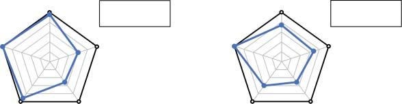
Figure1.1 Diagramssummarizingthecurrentstatusofautomotivefuelcellsystems (a)andstacks(b)relativetoDOEtargets.Source:ReproducedfromU.S.Departmentof energy[4]/https://www.hydrogen.energy.gov/pdfs/20005-automotive-fuel-cell-targetsstatus.pdf/Publicdomain.
progress.Thesemetricsarecommonlyusedasspecificationsforfuelcellproducts andtargetsforfuelcellresearch,development,anddemonstration(RD&D) programs[1–3].Forinstance,systemandstack-leveltargetsforautomotivefuel cellssetbytheU.S.DepartmentofEnergy(DOE),alongwithrespectivestatus estimates,areillustratedinFigure1.1[4].Themostusedmetriccategoriesinclude cost,durability,efficiency,systemsize,andflexibility.Eachofthese,aswellas specificmetrics,willbedescribedbelow.
Thereareseveraldifferentmetricsincommonusethatdescribethesizeoffuelcell systems,combiningthepoweroutputandphysicalmassorvolumeofthesystem. Poweroutputmaybegivenasgrosspower–thetotalelectricalpoweroutputofthe fuelcellstack–orasnetpower–thepoweroutputofthestackminusthepower consumptionofthesupportingbalanceofplant(BOP).Thisdistinctionmustbe specifiedtoavoidconfusionandmaybeincludedinthepowerunits(askWgross or kWnet ,forexample).Toaddressapplication-drivensystemsizeandweightrestrictions,thepoweroutputcanbegivenasanabsolutetotal,perunitweightofthe system(thisisknownasthespecificpower,withunitssuchaskWkg 1 ),orperunit volumeofthesystem(thisisknownasthepowerdensity,withunitssuchaskWl 1 ).
Theenergyconversionefficiencyofafuelcellsystemcanbespecifiedineither theelectricalpoweroutputperfuelinput(e.g.kWhkg 1 H2 )orasapercentageofthe fuel’slowerheatingvalue.Fuelcellsgenerallyaremoreefficientatlowpowerthan athighpower,andtheefficiencyiscloselytiedtothefuelcellperformance,as thesamemechanismsofvoltagelossdecreaseboth.Therearethereforedifferent definitionsforsystemefficiencyspecifiedatdifferentperformancelevels,most commonlyatthepeakefficiency(atlowpower),peakorratedpower,oranaverage efficiencyoveraparticulardutycycle.
Fuelcelldurabilityorlifetimeiscommonlyspecifiedasthenumberofhoursof operationbeforeacertainlevelofdegradationisreached.While,inpractice,the tolerablelevelofdegradationwillvarydependingontheuser’sneeds,itisalsouseful tousestandardizedendoflifedefinitionssuchas10%voltagedegradationatrated powerforbenchmarkingpurposes.Itisalsoimportanttorecognizethatdegradation
1.1OverviewofFuelCellApplicationsandSystemDesigns 5 ratesandlifetimesforfuelcellsystemswilldependonthedutycycleandstressors ofeachapplication.
Thecostofafuelcellsystemisanimportantmetricbutismorechallengingto determinethanothermetricsthatarerootedinthephysicalorengineeringparametersofthesystem.Theactualcostofdeployedfuelcellsystemsisofinterestinbusinesstransactionsandtoassesscurrentmarketcompetitiveness.Theprojectedcostof fuelcellsystemsusingearlierstage,lab-demonstratedtechnologies,andlargermanufacturingscalesisalsousefulfortrackingadvancesintechnologyandinforming researchanddevelopment(R&D)needs.Thecostoffuelcellsystemsiscommonly specifiedperpoweroutput(e.g.$kWnet 1 )althoughthismetricdependsonboththe systemsizeandthedefinitionofthesystemboundaries(fuelstorage,powerelectronics,andothercomponentsarecommonlyexcludedfromthefuelcellsystem, althoughsystemdefinitionsvary).
Flexibilityandrobustnessareumbrellaconceptsthatencompassmanydifferent potentialmetricsfortheabilityofthefuelcellsystemtoadjusttoprovidepowerasit isrequired.Theseincludethetimerequiredtostartthefuelcellsystem,itscapability tostartandsustainpowerundercoldorhotconditions,itsabilitytoquicklyadjust tovaryingpowerdemands,andthereliabilityofthesystem.
Itisimportanttorecognizethatthevariousaspectsoffuelcellsystemsthatare describedbythesemetricsareinterrelated.Forinstance,analterationtoafuelcell systemthatlowersitscostmayalsoimpactitspoweroutput,efficiency,anddurability.Compositemetricsthatconstrainrelatedmetricsinaparticularwaycanthereforealsobeuseful.Forexample,DOEhasintroduceda“durability-adjustedcost” metricforautomotivefuelcells,whichdescribesthecostofan80-kWnet fuelcell systemthatalsomeetstherequirementsfor8000houron-roaddurability[5].
1.1.2FuelCellSubsystemsandBalanceofPlant(BOP)Components
FuelcellsrequiresupportingBOPequipmenttoprovidehighperformanceanddurability,includingthesupplyofairandfuel,cooling,andsystemmonitoringandcontrol.Itisimportanttounderstandthecommonsubsystemsandcomponentsusedfor thesepurposes.State-of-the-artfuelcellsystemdesignsaregenerallyproprietary, butrepresentativemodelsystemshavebeendevelopedtoprovidepublicinformation.Forinstance,theDOEhasfundedthedevelopmentofamodelautomotive fuelcellsysteminacollaborationbetweenStrategicAnalysis,Inc.andArgonne NationalLaboratoryandwithfeedbackfromtheU.S.DRIVE(DrivingResearchand InnovationinVehicleefficiencyandEnergysustainability)Partnership[6,7].This modelsystemisausefulresourceforunderstandingthesubsystemsandcomponentsintransportationfuelcellsystems.Similarmodelsystemsarebeingdeveloped formedium-andheavy-dutyvehicles[8–10]andhavealsobeendevelopedforstationaryandotherfuelcelltypes[11–14].
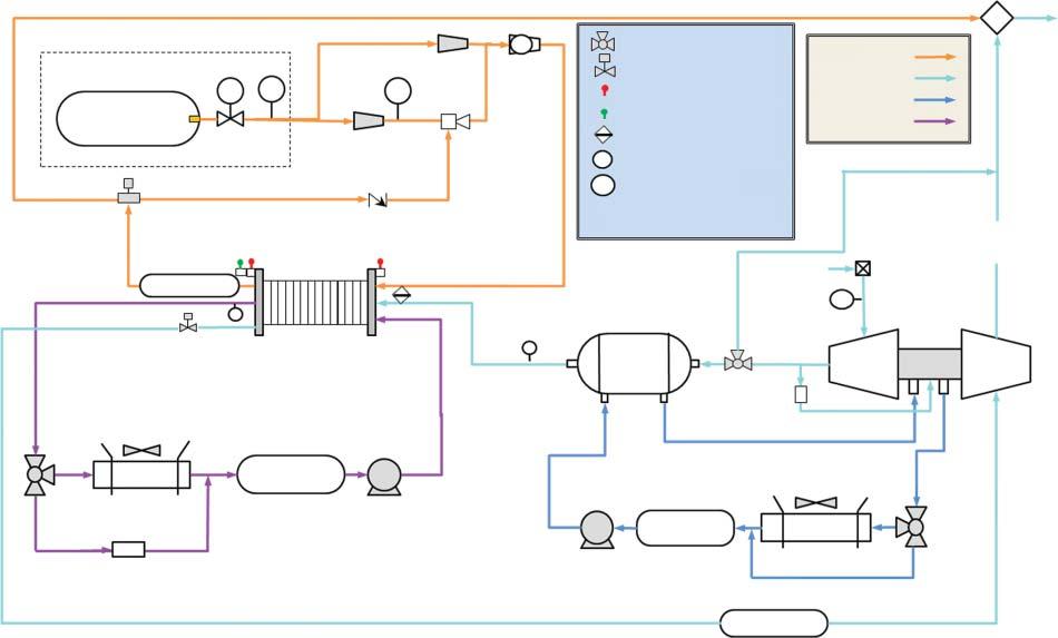
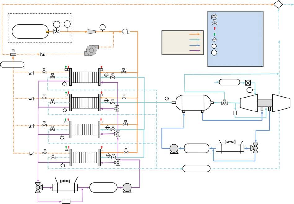
Examplediagramsoffuelcellsystemsforautomotiveandheavy-dutyvehicle applicationsareshowninFigure1.2.Thesediagramsprovidearepresentative illustrationoftypicalBOPcomponentsandsubsystemsintransportationfuelcell systems.
80-kW Automotive System
Differential
Anode
Figure1.2 Schematicsofrepresentativefuelcellsystemdesignsforautomotive(top)andheavy-dutyvehicle(HDV)applications(bottom)illustrating majorbalanceofplantcomponentsandsubsystems.Source:ReproducedfromRef.[6].
275-kW HDV System
Hydrogen from tanks
Compressed hydrogen tank
coolant loop
Differential
8 1System-levelConstraintsonFuelCellMaterialsandElectrocatalysts
Asthepower-producingcomponent,thestackistheheartofthefuelcellsystem. Thestackisacollectionofindividualgalvaniccells,eachofwhichprovides <1V whenoperating,connectedinseriestocreateapowerdevicethatprovidesahigher, moreusefulvoltage.Insomeapplications,multiplestacksmaybeusedtogetherfor modular,higherpowersystems.Eachcellcontainsamembraneelectrodeassembly (MEA),whichistheelectrochemicallyactivestackcomponent,withdiffusionmedia (gasdiffusionlayersandmicroporouslayers)oneachelectrodeencouraginguniform distributionofreactantsovertheMEAandremovalofwater.MEAsareconnected inthestackbyelectricallyconductivebipolarplatestocollecttheelectriccurrent produced,whichincludeflowchannelsfacingtheMEAstodeliverreactantstothe electrodes.Bipolarplateassembliesalsoincludecoolantchannelsrunningbetween (andseparatedfrom)theMEAstoremovewasteheatfromthestack.Gasmanifoldsdistributegasesbetweenthecellsinthestack,andgasketsareincludedtoseal gaswithinthedesiredelectrodes.Thestackalsoincludesstructuralcomponents, includingtierodsthatholdthecellstogetherandhousingthatenclosesthestack.
Fuelmustbesuppliedandpreparedforthefuelcellsystem,requiringdifferent BOPcomponentsdependingonthetypeoffuel.Ifhydrogenisthefuel,the preparationrequiredisminimal:thepressureandflowrateofhydrogentothe stackmustbecontrolled,andinsomecasesthehydrogenmaybehumidified. Unusedhydrogenmayalsoberecirculated.Morecomplexmolecules,suchas alcoholsorhydrocarbons,mayalsobeusedasfuelfordifferenttypesoffuelcell systems.High-temperaturefuelcells(e.g.solidoxide)canusecomplexfuelsdirectly, reformingtheminternallyinthestack.Low-temperaturefuelcellsmayincludean externalreformer,whichproduceshydrogenfromthefuelandmustalsoremove by-products,suchascarbonmonoxide,thatareharmfultothefuelcell.
Fuelcellsystemsalsorequireairtobesuppliedtothefuelcellstack.Toenable high-powerperformance,theairistypicallypressurizedbyacompressor,which maybeasimplecompressororacompressor-expandermodule,whichrecoups someenergyfromthepressurizedoutletstreamtoimproveoverallefficiency.Compressionheatstheairsupply,soprecoolingmaybenecessarybeforetheairenters thestack.Theairsupplymayalsobehumidifiedtoensureoptimalperformanceof membraneandelectrodes,andairmustbefilteredtoremovepotentiallyharmful contaminants.
Thethermalmanagementsubsystemremoveswasteheatfromthefuelcellsystem,usingcoolanttotransferheatfromthestack(andotherBOPcomponents, suchasthecompressor,asneeded)totheradiator.Thermalmanagementsubsystemstypicallyconsistofpumps,coolantlines,andradiators,althoughtheradiator issometimesconsideredtobeexternaltothefuelcellsystem.Multiplethermalmanagementsubsystemsmaybeused,suchasahigh-temperatureloopforthefuelcell stackandalow-temperatureloopfortheairprocessingsubsystem.
Thefuelcellsystemalsoincludescomponentsusedtomonitorandcontrolthe system.Numeroussensorsareusedinfuelcellsystems,includingstackvoltageand currentmonitors,pressureandtemperaturesensorsatdifferentpointsinthesystem,andhydrogensensorstodetectleaks.Thesesensorsprovideinformationto thesystemcontroller,whichdirectsthesystemtodeliverrequestedpower,while maintainingsafeoperationandavoidingconditionsthatmaydegradethefuelcell.
1.1OverviewofFuelCellApplicationsandSystemDesigns 9
Severalothersystemsandcomponentscommonlyaccompanythefuelcellsystem, butarenotconsideredapartofit,suchasthefuelstoragesystem,powerelectronics, andhybridbatteries.Theboundariesbetweenthefuelcellsystemandtheseother systemsnecessaryforapplicationsareoftennotdefinedconsistently.However,these externalsystemshaveminimalimpactonthechoiceoffuelcellmaterialsandsowill notbecoveredinthischapter.
1.1.3ComparisonofFuelCellSystemsforDifferentApplications
Thedesignoffuelcellsystemsandthetechnologiesusedvarysignificantlybetween differentapplications.Fortransportationfuelcellsystems,flexibilityandfaststartup arecritical,makingPEMfuelcellsthepreferredtechnology.Forautomotiveapplications,thefuelcellsystemistypicallysizedtoprovidearound100kWratedpower andisusuallyaccompaniedbyahybridenergystoragebatterytosupporttransient andpeakpowerdemands.Largerfuelcellsystems(hundredsofkWtoseveralMW) withmultiplestacksareusedforheavy-dutyvehicles,whilesmaller(uptotensof kW)butsimilarsystemsareusedformaterialhandlingvehiclessuchasforklifts. Transportationfuelcellsystemsaretypicallydirecthydrogenfueled,makingthefuel supplysubsystemrelativelysimple.Thecompressedairsupplyandheatrejectionare bothveryimportanttoenablehighpowerdensityandspecificpower.Alowcostis importantforthefuelcellsystemtocompetewithincumbentcombustionengine technologies.Durabilityisalsoakeyconcernfortransportationfuelcells,aspowertrainsarerequiredtoendurethousandsofhoursofoperationforautomobilesand tensofthousandsofhoursforheavy-dutyvehicles.Therelativeimportanceofdifferentsystemmetricsvariessignificantlybetweendifferenttransportationapplications aswell.Forexample,automotivefuelcelldevelopersprioritizeloweringcapitalcost andimprovinghigh-powerperformancetoenablesystemsizeandcostreductions. Incontrast,fulllifecyclecostsareimportantforcommercial,heavy-dutyvehicles, makingdurabilityandefficiencyimportantpriorities.Furthermore,forheavy-duty vehicleapplicationsthatcarryheavyloads,thefuelcellsystemneedstobedesigned todeliverhighpowerformoresustainedperiods,whichcancreatemoreharshconditionsforfuelcellmaterials.
Stationaryfuelcellsystemsvarywidelyinscalefrom <1kW“micro-CHP”residentialsystemstolargemultimegawattsystems.Forbackuppowersystems,flexibilityandresponsivenessarecritical,soPEMfuelcellsaretypicallyused.Because backuppowersystemsoperateonlyasmallfractionofthetime,capitalcostdominatestheiroverallcost.FordistributedpowerandCHPapplications,systemsare typicallyoperatedcontinuouslyforverylongperiods,makingdurabilityandefficiencyveryimportant.Thefuelprocessingsystemisalsoimportantforstationary fuelcellsystemsfueledbymethane(naturalgasorbiogas).Stationaryfuelcellshave minimalconstraintsonthesystemsizeorweight.
Forspecialtyapplicationssuchasmaterialhandling,fuelcellsmustprovideat leastequivalentperformancewithoutsignificantchangesinfunctionality,size, andcounterbalanceweightcomparedtotheincumbenttechnology.Theymust provideshortbursts(15–20seconds)ofhighpowerforliftingaheavyload,plus
1System-levelConstraintsonFuelCellMaterialsandElectrocatalysts
sustainedpowertodrivetheequipment.Ontheotherhand,portablefuelcell systemstypicallyhavelowpowerrequirements.However,theyaresubjectto extremesystemsizeandweightlimitations,andoftenaredesignedtominimize therequiredBOP,forexamplebyoperatingatornearambientpressure.Because theseconstraintsimpactthefuelstoragesystemaswell,liquidfuelsareofinterest fortheseapplications.Costmayormaynotbeaseriousconstraintdependingon theapplication;forconsumerelectronics,lowcostsarerequiredtocompetewith Li-ionbatteries,whichhaveseenrapidlyfallingpricesinrecentyears.However,for militaryorotherspecialtyapplicationshighcostsmaybeacceptable.
1.2Application-derivedRequirementsandConstraints
Thissectioncoversconstraintsonfuelcelloperationandmaterialchoicesthatare imposedbythesystemandapplicationrequirements.Fuelcellmaterialsmustmeet allsystem-levelrequirementssimultaneously,whichmakessomeotherwisepromisingmaterialsinfeasible.Themostfundamentalrequirementofafuelcellsystem istoprovidethepowerdemandedbytheapplication.Thisrequirementincludes twobroadcategories:(i)maximumpowerperformance,eitherinstantaneousor sustained,and(ii)flexibilitytodeliverpowerunderavarietyofconditionsandin responsetochangingdemand.Thefuelcellsystem,components,andmaterials mustalsobedurabletoprovidetherequiredperformancenotonlyinitiallybutalso afterextensiveuseandexposuretopotentiallydamagingconditions.Finally,fuel cellsystemsmustbeavailableatlowcosttobecompetitivewithalternativepower systems,consideringbothinitialcapitalandoperatingcosts.Itisimportanttonote thatperformance,durability,andcostareinterrelated,whichallowsfortrade-offs betweenthethree,dependingonthelifecyclerequirementsoftheapplication.
1.2.1FuelCellPerformanceandtheHeatRejectionConstraint
Cell-levelperformanceisafundamentalissueunderlyingthesystem-levelpower density,specificpower,cost,andefficiency.Thefuelcellsystemmustbesizedto deliverthepowerrequireddependingonthenatureoftheapplicationandthesystemarchitecture.Forafuel-cell-dominanthybridizationscheme,thefuelcellmust delivertherequiredsustainedmaximumpower,astherelativelysmallbatterycan addtothepeakpowerforalimitedperiodoftime.Forabattery-dominanthybridizationscheme,thefuelcellinsteadmustdelivertheaveragepowerrequired,withthe batterysupplyingpowerforpeakdemand.Forexample,fuel-cell-dominantautomotivefuelcellsoperatemostofthetimeatlow-powerconditions,wherethesystem ismostefficient,butoccasionallyrequireahighratedpower(suchasforhighway merging).Thismakesratedpowerimportantbecauseitdrivessystemsizerequirementsandisdirectlyrelatedtocost.
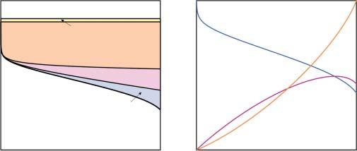
Thevoltagelossmechanismsthatdeterminefuelcellperformance,illustratedin Figure1.3a,havebeenthoroughlydescribedinmanyothertextsonfuelcellsand electrochemistry[15,16],sowewillonlybrieflyrecapthemhere.Theidealpotential
Figure1.3 Illustrationsof(a)thevoltagelossmechanismsthatcontributetothefuelcell polarizationcurveand(b)therelationshipamongthefuelcellvoltage,electricalpower production,andwasteheatthatmustberejected.
(foraperfectlyreversibleprocess)isdeterminedbytheoverallthermodynamics ofthefuelcellreaction,correspondingto1.23Vforahydrogen-oxygenfuelcell atstandardambienttemperatureandpressure[15].Nonstandardthermodynamic conditionsmodifythispotentialasdescribedbytheNernstequation,butthe correctionisgenerallysmall(ontheorderof10mV)forPEMfuelcells.Theactual voltageofanoperatingfuelcelldependsonthecurrentdensityandisdetermined byvoltagelossesfromreactionkinetics,Ohmicresistance,andmasstransport.
Thelargestlossforlow-temperaturefuelcellsundertypicalconditionsisdue totheslowkineticsoftheoxygenreductionreaction(ORR)onthecathode.ORR kineticsforPEMfuelcellsarewelldescribedbytheTafelapproximation[17]and havearoughlylogarithmicdependenceonthecurrentdensity,growingrapidlyat lowcurrentdensityandthenvaryingslowlyatmoderatetohighcurrentdensities. ORRkineticlossesareimpactedbytheintrinsicactivityofacatalystmaterial,the activesurfaceareainthefuelcellelectrode,andinteractionswiththepolymer electrolyteintheelectrode(theionomer),whichmaycoattheactivesurface.By contrast,thekineticsofthehydrogenoxidationreaction(HOR)atthefuelcell anodeareextremelyrapid,andHORkineticlossesforPEMfuelcellsaretypically negligible,evenwithextremelylowcatalystloadings.Forhigh-temperaturefuel cellskineticchallengesareminimal.
Ohmiclossesincreaselinearlywithcurrentdensityinproportiontotheoverallresistanceofthecell.InPEMfuelcellsthemembraneistypicallytheprimary sourceofohmicresistance,withtheelectrodeionomeralsocontributingsignificantlyundersomeconditions.Thecarbon-basedmaterialscommonlyusedforgas diffusionmediaandcatalystsupportscontributeminimalresistance,althoughcontactresistancesandless-conductive,corrosion-resistantalternativematerialsmay contributesignificantohmiclosses.Forhigh-temperature,solidoxidefuelcells,the ohmicresistanceoftheceramicelectrolytetypicallydominatesoveralllosses.
Masstransport-relatedlossesarenegligibleatlowcurrentdensitybutgrowrapidly athighcurrentdensity.Theprimarysourceoftransportlossesforhydrogen-airfuel cellsisoxygendiffusioninthecathode.Thisincludesbothbulkoxygentransport throughtheelectrodeandlocaloxygentransportresistanceassociatedwithoxygen
1System-levelConstraintsonFuelCellMaterialsandElectrocatalysts
diffusiontoalimitednumberofcatalyticallyactivesites,whichisaparticularly importantandchallengingproblemforlow-platinumgroupmetal(PGM)-loaded electrodes[18].Inadequateremovalofproductwatercanalsoleadtocondensationor“flooding,”leadingtosignificantmasstransportlosses.Theeffectivenessof masstransportisdeterminedbytheporousstructureofthediffusionmediaand electrodes,includingthecatalystsupportstructureandionomerdispersion.
Beyondsimplesingle-cellperformance,heatrejectionputsanimportantconstraintonperformance.AsillustratedinFigure1.3b,asthevoltagelossesincrease athighercurrentdensities,theefficiencyofenergyconversioninthefuelcell declines.Consequently,theincreaseinpoweroutputslows,eventuallyreachinga peakathighcurrentdensityandhighvoltageloss.Thisalsoleadstoanaccelerating growthintheamountofwasteheatproducedbythefuelcell.
Duringsteady-stateoperation,thefuelcellsystemmustremoveallwasteheatproducedbythefuelcellsstack.Forbriefperiods,thestackcanbeallowedtogenerate excessiveheatifitisatarelativelylowtemperature,sohigherpowerispossible intransientoperationthanthecontinuouspowerrating.Theheat Q rejectedfrom radiatorcanbesimplydescribedbyNewton’slawofcooling:
Q = hAΔT
where h istheheattransfercoefficient, A issurfacearea,and ΔT = T c T a isthe differencebetweenthecoolanttemperature T c andtheambienttemperature T a .For agivenradiator, h and A arefixed,so Q/ΔT muststaybelowacertainvalue.This makesaparticularvalueof Q/ΔT ametrictodescriberadiatorcapacity,whichis limitedforvehicleapplications.Tomeetthisheatrejectionconstraint,itispossibleto eitherlowertheamountofwasteheatproducedorraisetheoperatingtemperature. Thissetsapracticallimitonthefeasiblefuelcelloperatingconditions[19].
Asimpleformularelatesthe Q/ΔT heatrejectionmetrictorated(continuous) poweroperatingconditions,particularlythecellvoltage V r ,whichdeterminesthe fractionofenergyconvertedtowasteheat,andthestackcoolantoutlettemperature T c ,whichdetermineshoweffectivelythatheatcanberejectedthroughtheradiator: Q ΔT = P
g isthegrosspowerratingofthestack,and V i istheidealcellvoltage. ThisrelationshipisillustratedinFigure1.4,whichshowsthedependenceofthe cellvoltageatratedpower V r on T c and Q/ΔT ,usingstandardassumptions[20]for anautomotivefuelcellsystem(90kWgross ratedpower,40 ∘ Cambienttemperature, and1.23Videalcellvoltage).Ingeneral,lowervoltages(andthereforehighercurrentandpowerdensities)canbeusedwitheitherahighercoolanttemperatureor higher Q/ΔT (i.e.radiatorsize).TheDOEhassetatargetforfuelcellheatrejection of Q/ΔT ≤ 1.45kWper ∘ Ctoenableuseofpracticallysizedautomotiveradiatorsfor fuelcellvehicles.
Meetingthisautomotiveheatrejectionconstraintcreatesastrongmotivationfor usinghighertemperature(e.g.94 ∘ C)andhigherpressure(e.g.2.5bar)operating conditionsatratedpower[19].Raisingthetemperatureallowshighercurrent