3D SCANNING FOR ADVANCED MANUFACTURING, DESIGN, AND CONSTRUCTION
GARY C. CONFALONE
JOHN SMITS
THOMAS KINNARE
East Coast Metrology
Topsfield, MA, USA
Copyright © 2023 by John Wiley & Sons, Inc. All rights reserved.
Published by John Wiley & Sons, Inc., Hoboken, New Jersey.
Published simultaneously in Canada.
No part of this publication may be reproduced, stored in a retrieval system, or transmitted in any form or by any means, electronic, mechanical, photocopying, recording, scanning, or otherwise, except as permitted under Section 107 or 108 of the 1976 United States Copyright Act, without either the prior written permission of the Publisher, or authorization through payment of the appropriate per-copy fee to the Copyright Clearance Center, Inc., 222 Rosewood Drive, Danvers, MA 01923, (978) 750-8400, fax (978) 750-4470, or on the web at www.copyright.com. Requests to the Publisher for permission should be addressed to the Permissions Department, John Wiley & Sons, Inc., 111 River Street, Hoboken, NJ 07030, (201) 748-6011, fax (201) 748-6008, or online at http://www.wiley.com/go/permission.
Trademarks: Wiley and the Wiley logo are trademarks or registered trademarks of John Wiley & Sons, Inc. and/ or its affiliates in the United States and other countries and may not be used without written permission. All other trademarks are the property of their respective owners. John Wiley & Sons, Inc. is not associated with any product or vendor mentioned in this book.
Limit of Liability/Disclaimer of Warranty: While the publisher and author have used their best efforts in preparing this book, they make no representations or warranties with respect to the accuracy or completeness of the contents of this book and specifically disclaim any implied warranties of merchantability or fitness for a particular purpose. No warranty may be created or extended by sales representatives or written sales materials. The advice and strategies contained herein may not be suitable for your situation. You should consult with a professional where appropriate. Neither the publisher nor author shall be liable for any loss of profit or any other commercial damages, including but not limited to special, incidental, consequential, or other damages. Further, readers should be aware that websites listed in this work may have changed or disappeared between when this work was written and when it is read. Neither the publisher nor authors shall be liable for any loss of profit or any other commercial damages, including but not limited to special, incidental, consequential, or other damages.
For general information on our other products and services or for technical support, please contact our Customer Care Department within the United States at (800) 762-2974, outside the United States at (317) 572-3993 or fax (317) 572-4002.
Wiley also publishes its books in a variety of electronic formats. Some content that appears in print may not be available in electronic formats. For more information about Wiley products, visit our web site at www.wiley.com.
Library of Congress Cataloging-in-Publication Data
Names: Confalone, Gary C., author. | Smits, John, author. | Kinnare, Thomas, author.
Title: 3D scanning for advanced manufacturing, Design, and Construction / Gary C. Confalone, John Smits, and Thomas Kinnare.
Description: Hoboken, New Jersey : John Wiley & Sons, [2023] | Includes bibliographical references and index. Identifiers: LCCN 2022051307 (print) | LCCN 2022051308 (ebook) | ISBN 9781119758518 (hardback) | ISBN 9781119758556 (pdf) | ISBN 9781119758563 (epub) | ISBN 9781119758532 (ebook) Subjects: LCSH: Scanning systems. | Manufacturing processes. | Power electronics. Classification: LCC TK7882.S3 C664 2023 (print) | LCC TK7882.S3 (ebook) | DDC 621.381/044--dc23/ eng/20221109
LC record available at https://lccn.loc.gov/2022051307
LC ebook record available at https://lccn.loc.gov/2022051308
Cover image: © Gorodenkoff/Shutterstock
Cover design: Wiley
Set in size of 9/13 and STIXTwo Text by Integra Software Services Pvt. Ltd, Pondicherry, India
This book is dedicated to our colleagues and coworkers who are always by our side to help and provide their expertise without hesitation. We would also like to extend our gratitude to our clients and vendors for providing advice, guidance, and material content for this book, but mostly for their unparalleled benevolence and friendships throughout the years. And finally, we especially want to thank our beloved wives and children for their patience and encouragement during the many evenings and weekends spent working on this text.
8.4
How to Use This Book
This book, written for the student, technician, designer, engineer, manager, and other manufacturing practitioners interested in acquiring and applying 3D scanning technologies and processes within their organization, aims to provide a broad foundation for ongoing learning. It covers all aspects of 3D scanning from the history of measurement, survey, and metrology to the practical applications of 3D scanning as it is used for data collection, analysis, and reverse engineering. We will explore applications ranging from radar bore-sighting to architectural engineering and construction with practical, useful, real-world case studies. The case studies further illustrate 3D scanning technology and demonstrate methodology through samples of varying applications and solutions without the burden of detailed theories.
Chapter 1 is an overview of the history of metrology, the science of measurement. From ancient times to modern day, methods and equipment are described to give the reader insight into the development of measuring methods, from handheld sticks to modern-day laser equipment.
Chapter 2 introduces the basics of laser scanning technology, beginning with a discussion of lasers, how they are created, what types exist, and the various classifications of laser instruments. The development of equipment using lasers for measurement will be reviewed, explaining the basic methodologies employed for scanning.
In Chapter 3 all of the varying instruments used to collect data are described. Laser trackers, laser scanners, and LIDAR systems are a few of the instruments to be reviewed for function, purpose, and practical applications.
Chapter 4 begins with a review of the software needed for processing scan data, how the software functions, and what are key capabilities to look for when comparing software. The chapter then explores point clouds and polygonal mesh files. What they are along with best practices for obtaining and processing the data. Data process techniques discussed include cloud and feature registration, along with polygonal meshing and cross sectioning for both engineering and architectural modeling as well as CAD to part analysis.
Chapter 5 explains the math behind data processing, analysis, and reporting. Critical to the application of data collection is the way it is reported to the end user. One must consider scaling and uncertainty to provide accurate and reliable data. Most important is the ability to report this data in a real-world coordinate system that makes sense to the designer as well as the end user.
Chapter 6 presents the concept of reverse engineering as used within the manufacturing and consumer industries. The varied uses of reverse engineering methods are described along with the use of 2D and 3D CAD modeling techniques unique to industrial metrology. Case studies are presented, providing the reader with real-life examples of the applications of laser measurement to modern-day projects.
Chapter 7 presents reverse engineering as used within the AEC (architectural, engineering, and construction) industry. Readers are led through the advantages scanning provides for modern-day design and construction, along with various applications of this useful technology, including clash detection, forensics, and BIM modeling. Case studies illustrate the use of multiple pieces of laser scanning equipment and the diversity of deliverables used by actual projects to provide timely and cost-saving solutions.
Chapter 8 is a brief analysis of emerging trends within the laser scanning industry, and what can be foreseen for future development for software, equipment, and applications.
Chapter 9 provides a number of resources and references for the reader, with listings of professional organizations, equipment, and software manufacturers. Universities and colleges that offer courses and degrees in metrology and the use of 3D laser scanning technology are given.
A Glossary of Terms is at the end of the book, a valuable reference for the reader to understand and define the many specialized terms and acronyms used in the metrology industry.
Navigating this book, you will be part of the journey in analyzing opportunities for the application of 3D scanning in your business or industry. Begin by identifying a problem or opportunity for which you would like to explore a scanning solution. Work through the major decision steps and post-processing needed to get to the desired end result, such as a point cloud or a solid model. The case studies will explain how others have addressed challenges and decisions to move 3D scanning forward in their business workflows. By the end of the book, you will be prepared to make a case for implementing 3D scanning technology into your next project.
History of Metrology
The regulation of weights and measures is necessary for science, industry, health care, and commerce. The importance of establishing uniform national standards was demonstrated by the drafters of the US Constitution, who gave Congress in Article 1, Section 8, the power to fix the Standard of Weights and Measures. “Weights and Measures,” said John Quincy Adams in 1821, “may be ranked among the necessaries of life to every individual of human society.”1
Weights and measures may be ranked among the necessaries of life, to every individual of human society. They enter into the economical arrangements and daily concerns of every family. They are necessary to every occupation of human industry; to the distribution and security of every species of property; to every transaction of trade and commerce; to the labours of the husbandman; to the ingenuity of the artificer; the studies of the philosopher; to the researches of the antiquarian; to the navigation of the mariner, and the marches of the soldier; to all the exchanges of peace, and all the operations of war. The knowledge of them, as in established use, is among the first elements of education, and is often learnt by those who learn nothing else, not even to read and write. This knowledge is riveted in the memory by the habitual application of it to the employments of men throughout life. (John Quincy Adams, Report to Congress, 1821)
1 Bucher (2004). The Metrology Handbook. https://ebookcentral.proquest.com/lib/umaine/reader. action?docID=3002524, p. 1–9.
3D Scanning for Advanced Manufacturing, Design, and Construction, First Edition. Gary C. Confalone, John Smits, and Thomas Kinnare © 2023 John Wiley & Sons, Inc. Published 2023 by John Wiley & Sons, Inc.
1.1 INTRODUCTION
To understand 3D laser scanning technology, a person must have an understanding of metrology. Metrology is defined as the science of measurement. It is the language that engineers use to communicate to manufacturers.
When studying science, technology, engineering, and math, you will use units and the universal language of metrology which was developed thousands of years ago and continues to evolve today. Often the parameters of these units are referred to as geometric dimensioning and tolerancing (GD&T). This language consists of formulas, numbers, and symbols that when interpreted correctly can yield the most magnificent of outcomes. It is the language of technical professionals in manufacturing and construction, or the language the designer uses to describe what he wants to the builder and end user. And once you learn this language and become indoctrinated into this world, you will see things in a different light. I often tell students to look at my coffee cup and tell me what you see. I go on to explain that everything in this classroom was designed by an engineer using a blueprint or a formula. The blueprint will dimension the cup; and the formula will define the contents. Both the blueprint and the formula use metrology to make sure they are built to the design specifications or the proper recipe.
So, you may ask, what does this have to do with 3D laser scanning. This book will focus on the applications of laser scanners as they are used to measure and reproduce 3D results. Often the reproduction of these results is referred to as Reverse Engineering or As-Built documentation. Both topics will be explored in the subsequent text.
1.2 THE HISTORY OF METROLOGY
Archeologists believe that measurement standards have been with us for over 6,000 years and probably longer. With the adoption of agriculture to what was once a nomadic species, humans needed a way to measure their land and crop yields to communicate fair trade to others. But measurement was not only limited to the agricultural industry, free trade also created a need for measurement in all facets of life in a growing industrial world market. This of course resulted in a wide variety of measurement systems being developed throughout the world.
It was not until 1875 that engineers and scientists began to establish an internationally recognized system at the “Metre Convention” held in Paris. At the Metric Convention of 1875, as it is called in English, a treaty was signed between 17 countries including the US to establish the international Bureau of Weights and Measures, which would work to standardize the four basic measurement standards: mass (weight), distance or length, area, and volume. [Today standardization also includes temperature, pressure, luminosity, and electric current.]
1.3 THE INTERNATIONAL SYSTEM OF UNITS (SI)
In 3D scanning and surveying, length, angle, area, and volume are the primary units of measure. The two systems used for specifying these units of measure in the world today are the Metric System and the British Imperial System.
The Metric System was developed in France in late eighteenth century and is maintained by the General Conference on Weights and Measures (GCWM). Since the metric system is almost universally used today, it is often referred to as the International System of Units and abbreviated SI (Système International d’Unités).
Units in the British Imperial System (BIS or IS) are derived from the English System of units which is rooted in historical units from both Roman and Anglo-Saxon units. To make things more complicated, the US Customary Measurement System is a system based on the English System which was the measurement system used in Britain prior to the introduction of the British Imperial System in 1826.
I know all of this can be confusing and you can only imagine what it was like hundreds of years ago before the internet was able to do a unit conversion. The differences between the US and British systems are only as they relate to volume and will not impact the discussions in this text. Our focus here will primarily be concerned with dimensional metrology.
A Message from the President to the Senate of the United State:
I transmit to the Senate for consideration, with a view to ratification, a metric convention between the United States and certain foreign governments, signed at Paris, on the 20th of May 1875, by Mr. E. B. Washburne, the minister of the United States at that capital, acting on behalf of this government, and by the representatives acting on behalf of the foreign powers therein mentioned. (Washington, March 10, 1876. Ulysses S. Grant)
1.4 THE HISTORY OF THE METRIC SYSTEM
With over 700 recorded units of measure in France, a movement was made after the French Revolution where engineers looked for standards that were based on pure natural occurring physics. Strangely enough around 1790, the Metre was introduced as one ten-millionth of the shortest distance from the North Pole to the equator (Quarter Meridian) passing through Paris. To define this, the measurements and construction of the standards were entrusted to the Institute of France and international representatives who served as deputies of this commission. Jean-Baptiste Joseph Delambre and Pierre-Francois Meçhain then set forth to identify the meter by making geodetic and astronomical measurements along the meridian from Dunkirk to Barcelona. This took 7 years of extensive survey triangulation work to complete. From these results there was constructed a one-meter bar of platinum whose length was measured between its two ends, and it became known as the “Meter of Archives.”
Table 1.1 Metric system – length units of measure
Base Unit Symbol Meter Equivalent
By 1795 the Decimal Metric system evolved to recognize the Metre as the standard unit of measure. This simplistic system soon became a weights and measures law throughout the globe noting also that a cube having sides of length equal to one-tenth of a meter was to be the unit of capacity, the liter, and the mass of a volume of pure water equal to a cube of one-tenth of a meter at the temperature of melting ice was to be the unit of mass, the kilogram.
Referring to the original standards became difficult over the years so to be more practical, the platinum bar that was held in Paris to define this metre (meter) was replaced 100 years later in 1889 by the International Geodetic Association with 30 platinum–iridium bars that were distributed throughout the world. It was not until 1960 that a new definition was derived using the physical properties of light. The spectral emission of Krypton-86 radiated light at 606 nanometers (orange) became the new international length standard from 1960 to 1983.
Today the meter is defined by research performed by the National Institute for Standards and Technology (NIST) as the length of light travel in 1/299,792,458 of a second in a vacuum. Table 1.1 lists the SI units of measure commonly used to define length.
1.5 THE HISTORY OF THE BRITISH IMPERIAL SYSTEM (IS)
So as not to be outdone by the French, the Imperial System of units was established by the British Weights and Measures Act of 1824. The imperial units were preceded by the Winchester Standards which were in place from 1588 to 1825. Derived from hundreds of Roman, Celtic, and Anglo-Saxon units, the British Imperial System was the primary measurement standard until the UK joined the European Economic Community in the 1970s. However, some imperial units are still in use today. One of those being the pint which is a very important standard frequently used by metrologists in Britain, the US, and throughout the world!
Because this book is focusing on 3D scanning, we will stick to the topic of dimensional metrology. Below we will walk you through the most common units of measurement as they relate to length and give a brief history of their origin. Most of the IS units will make sense after learning the history or the etymology of the unit identifier. These include units such as the furlong, the mile, and the yard. Other units like the hand, foot, or pace have origins that are a bit more self-explanatory.
1.5.1 Inch
There are many historical accounts of how the inch was derived. Earliest would be the Anglo-Saxon definition of the inch as being the length of three grains of barley placed end to end. Later in history, King David I of Scotland and his court of Weights and Measures defined the inch as the width of an average man’s thumb, measured at the base of his thumbnail.
1.5.2 Thou, Mil, and Tenth
When working in the field of metrology one must learn to adapt to the various industries and national systems under discussion. With the growing popularity of the metric system here in the United States, I often see people refer to the millimeter as a “mil” when in fact the “mil” is an abbreviation that refers to 0.001 or one-thousandth of an inch. Mil is derived from the Latin word Mille meaning one thousand. The mil is interchangeable with the other term for this measurement referred to as the “thou.” Thus, one thousand thou equal one inch; and one thousand mils also is equal to one inch.
Much like the ambiguous challenges children face when spelling words in the English language, metrology will also become second nature after time but should not be taken for granted. For the students and readers not yet fully immersed in the manufacturing industry I believe it is worth building on the above and not assume that all abbreviations are clear. In discussions among engineers and machinists you will always hear the terms, thou, mil and tenths when referencing precision tolerances. We have determined above that the terms thou and mil are synonymous and refer to 0.001 inch. If you are not included in these social circles and hear the term “tenth” one may naturally assume it is indicating one-tenth of an inch. After all that makes perfect sense. But what it is actually defining is one-tenth of one-thousandth of an inch or 0.0001 inch. We won’t get too bogged down by these facts, but I believe this was simply worth noting to students of the industry and others new to the field because we often see this confusion with young engineers.
1.5.3 Hand
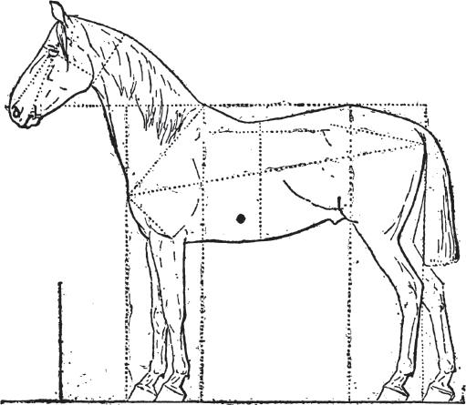
Still in use today is the ancient tradition of using the “hand” to measure the height of horses. Horses from the ground to the top of the shoulder (withers). The unit was originally defined as the breadth of the palm including the thumb. A statute of King Henry VIII of England established the hand at four inches. Therefore, a horse that measures 15 hands would be 60 inches tall at the shoulder (Figure 1.1).
1.5.4 Foot
Like the inch, there are many rumored origins of the foot as a length standard. The first recount was said to be around 2575 BC where it is speculated that the Greeks and Romans adopted the foot standard from the Egyptians. In all accounts, and like so many other units based on the human body, it is assumed that the origin of the foot standard was the length of a man’s foot (Figure 1.2).
British history states that King Henry I decided his foot would be a standard for length, as pacing out length measurements was a very common practice in land surveying. This foot measurement standard was to be a booted foot rather than a bare foot. This was probably the case because folks taking these measurements or paces were donning boots while performing these measurement tasks.
Figure 1.1 Equine metrology
Figure 1.2 Foot length standard
1.5.5 Cubit
The earliest recognized standard for measurement is the Egyptian Cubit. This standard is based on the forearm length of the Pharaoh reigning around 3000 BC. One can easily see how this could be an issue as Pharaohs will change from one generation to the next. The cubit therefore had a range of approximately 43–53 centimeters throughout history. The flood level of the Nile circa 3000 BC was defined as 6 cubits and 1 palm; where 1 palm is equal to 4 fingers and 6 palms is equal to a cubit.
1.5.6 Yard
The first yard followed suit with most of the other standards in that it was a reference to the human body but in many various ways. It is documented that this standard was based on the single stride of a man; the breadth of a Saxon’s chest; or the length of a man’s girdle (belt). Yet others believe it was originally a cubic dimension, or a unit of volume. Whichever it may have been at the time, not unlike the foot and the inch, there were many variations in this standard. For this reason, many centuries of measurement uncertainty caused much disagreement in trade and contentious land disputes.
During the reign of Edgar the Peaceful (959–963 AD) he dictated that a bar he designated “the yardstick” held at the Cathedral of Winchester should be observed as the standard throughout his Realm.
And again, with a new King comes a new measurement definition. Like the foot, in the twelfth century, King Henry I redefined the yard as the distance from his nose to the thumb of his outstretched arm. Oddly as it may seem, Henry was only off by one-hundredth of an inch from today’s standard!
1.5.7 Chain
Early surveyors often used a chain as a useful tool in their measurement process. Many of these chains tended to vary in length. Along came Edmund Gunter (1581–1626), a well-known mathematician and astronomer in the day. Gunter made many important scientific discoveries, one of those being his process of triangulation to survey and plot land area. He employed a chain that would allow him to take linear measurements between topographical features in the land to plot and calculate the area. For this the Gunter Chain, as it was called, became known as a standard of length and was equal to 66 feet.
1.5.8 Rod
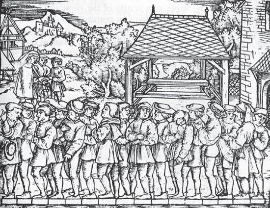
Edmund Genter who we just spoke of, also standardized the rod as a unit of measure in 1607. A rod, also called a perch or pole, was defined as one-quarter of a chain (16½ feet) (Figure 1.3).
Figure 1.3 Determination of the rod, using the length of the left foot of 16 randomly chosen people coming from church service
Source: Wikipedia. Woodcut published in the book Geometrei by Jakob Köbel (Frankfurt, c. 1535). WIKI.
Chains and rods were used for many centuries as land deal transactions were rapidly growing in North America and Australia. Our most famous surveyor George Washington used a rod which was fashioned out of dimensionally stable and somewhat flexible wrought iron. These rods were portable and easy to manipulate through the forest and bushes by a single man surveyor.
1.5.9 Furlong
Another old English unit of length was the furlong. This unit was simply derived from the average length of a plowed furrow (“furrow-long,” or furrow). The length was determined by the amount of time a team of oxen could plow before resting. This was a sensible length for farmers that later evolved into the acre. A standard furrow is 660 feet (220 yards) long or ⅛ mile.
1.5.10 Fathom
The fathom is a measure of length that is equivalent to 72 inches (6 feet) and was primarily used by maritime navigators to measure the depth of water. Its origin is believed to come from the English word “faethm” which means outstretched arms. This is the longest unit originating from the human body comparison as it is defined by the distance from the middle fingertip of the right hand to the middle fingertip of the left hand. This is also the length at which a man could extend his arms while measuring rope which was very suitable.
Although there are many interpretations of its origin, the most popular among historians for the term “to deep six” something, comes from its reference to a burial at sea where it was required as late as the early 1900s to perform a burial in at least 6 fathoms of water to assure it will not wash ashore. Today in US the depth has increased to 100 fathoms (600 feet) of ocean water that is 3 nautical miles from shore.
1.5.11 Acre
It is worth noting the history of the Acre for the benefit of the Engineering and Surveying students and readers. Tracing back to Middle England agriculture, the acre was thought to be defined by the quantity of land that could be tilled with a wooden plow and yoke pulled by oxen in the span of one day (Figure 1.4). When you plow, you make a trench in the soil called a furrow or furlong as previously noted. One pass across a field would leave a trench one “furrow long.” The number of furrows cut in one day was adopted by England to be the standard known as the acre. It was later given a new and more distinct definition as one-tenth of a furlong by the Anglo-Saxons, which was approximately 660 feet in length. From this we can calculate 40 × 4 rods is roughly equivalent to 660 × 66 feet, which is where we obtain the area of 43,560 square feet used to define an acre today. Today the acre is most commonly used by the United States and United Kingdom to describe large spans of land such as farmland, forests, and building property. In countries that employ the Metric System of units, area will be measured in squaremeters (m2). It is therefore important to be able to convert from the US customary and Imperial System to the more commonly used International System of units (SI). Below are common conversions of acres, miles, and meters units of measure:
1 acre
43,560 square feet (4046.856 m2)
1 square mile 640 acres
Figure 1.4 An acre was determined by the amount of furrows plowed in 1 day
In Chapter 9 a more comprehensive table of US and metric measurements and units is provided for the reader’s reference.
1.5.12 Pace
In ancient Rome, the pace ( passus) was measured from the heel of one foot to the heel of the same foot when it next touched the ground as done in a normal step when walking. This is a convenient unit for measuring walking distances such as the mile as described below. A standard pace is 5 Roman feet long.
1.5.13 Mile
As interesting as the Egyptian cubit is another historic length standard known as The Roman Mile deriving from the Roman mille passus, or “thousand paces.” This unit of measure was defined as a count of 1,000 paces of which each pace consisted of 2 steps or 5 Roman feet. Thus, the Roman Mile was equal to 5,000 Roman feet. Roman Armies would literally put stakes in the ground marking out each mile as they marched. However, measurements taken this way introduced variables of uncertainty beyond physical attributes. The conditioning of the soldiers and the weather that they marched in would impact the stride and therefore the length of the mile.
Now that you know how many of the old measurement units that have stood the test of time were derived, Table 1.2 below illustrates today’s definition of the seven (7) base units and how they are defined in most of the modern world.
Table 1.2 SI-based units and standards
Base Measure Name Symbol Definition
Time second s
Length metre m
Mass kilogram kg
The second is defined by taking the fixed value of the cesium frequency ∆νCs, the unperturbed ground-state hyperfine transition frequency of the cesium-133 atom, to be 9,192,631,770 when expressed in the unit Hz, which is equal to s−1.
The length of the path traveled by light in a vacuum during a time interval of 1/299792458 of a second.
Defined (since 2019) by taking the value of the Planck constant, h, to be 6.62607015 × 10 −34 when expressed in the unit J s, which is equal to kg m2 s−1 (Continued )
Table 1.2 (Continued)
Base Measure Name Symbol
Electric current ampere A
Thermodynamic temperature kelvin K
Amount of substance mole mol
Luminous intensity candela cd
Definition
Defined (since 2019) by taking the value of the elementary charge, e, to be 1.602176634 × 10 −19 when expressed in the unit C, which is equal to A s.
Defined (as of 2019) by taking the value of the Boltzmann constant, k , to be 1.380649 × 10 −23 when expressed in the unit J K−1, which is equal to kg m2 s−2 K−1
Contains (since 2019) exactly 6.02214076 × 10²³ elementary entities. This number is the fixed numerical value of the Avogadro constant, NA , when expressed in the unit mol−1.
The luminous intensity, in a given direction, of a source emitting monochromatic radiation of a frequency of 540 × 1,012 Hz with a radiant intensity in the direction of 1/683 watt per steradian.
1.5.14 Why Isn’t the US Adopting the Metric System?
Many years ago, I recall learning the Metric System in grammar school. We were told that within a few years the United States would be switching to the Metric System, and it would become our primary system of measure. After all, it was the universal language and much easier to use. It was a big topic of discussion in every household in America, and I even recall Saturday Night Live doing a skit about the new Metric Alphabet now called the “Decabet” which would shorten our current alphabet to 10 letters! So, it wasn’t a surprise when I graduated engineering school and joined the workforce that I was to be part of an aerospace program that was decidedly going to design an aircraft entirely using the metric system. This would make support easier as the mechanics would only need metric tools and would hopefully make the aircraft more attractive to the international market. Imagine a toolbox with one set of metric tools to service the entire fleet. All of the hardware was to be metric and all of the hydraulic and electrical fittings were to be Metric. This plan sounded great; however, there were a lot of suppliers that needed to be convinced and there really was not much in terms of spare metric hardware within the corporation. This did cause many delays because lean manufacturing practice was