[Ebooks PDF] download Flight simulation software: design, development and testing david allerton ful
Visit to download the full and correct content document: https://ebookmass.com/product/flight-simulation-software-design-development-and-te sting-david-allerton/
More products digital (pdf, epub, mobi) instant download maybe you interests ...
Introduction to Software Testing: A Practical Guide to Testing, Design, Automation, and Execution 1st Edition Panagiotis Leloudas
Effective Software Development for the Enterprise: Beyond Domain Driven Design, Software Architecture, and Extreme Programming 1st Edition Tengiz Tutisani
All rights reserved. No part of this publication may be reproduced, stored in a retrieval system, or transmitted, in any form or by any means, electronic, mechanical, photocopying, recording or otherwise, except as permitted by law. Advice on how to obtain permission to reuse material from this title is available at http://www.wiley.com/go/ permissions.
The right of David Allerton to be identified as the author of this work has been asserted in accordance with law.
Registered Offices
John Wiley & Sons, Inc., 111 River Street, Hoboken, NJ 07030, USA
John Wiley & Sons Ltd, The Atrium, Southern Gate, Chichester, West Sussex, PO19 8SQ, UK
Editorial Office
111 River Street, Hoboken, NJ 07030, USA
For details of our global editorial offices, customer services, and more information about Wiley products visit us at www.wiley.com.
Wiley also publishes its books in a variety of electronic formats and by print-on-demand. Some content that appears in standard print versions of this book may not be available in other formats.
Limit of Liability/Disclaimer of Warranty
While the publisher and authors have used their best efforts in preparing this work, they make no representations or warranties with respect to the accuracy or completeness of the contents of this work and specifically disclaim all warranties, including without limitation any implied warranties of merchantability or fitness for a particular purpose. No warranty may be created or extended by sales representatives, written sales materials or promotional statements for this work. The fact that an organization, website, or product is referred to in this work as a citation and/or potential source of further information does not mean that the publisher and authors endorse the information or services the organization, website, or product may provide or recommendations it may make. This work is sold with the understanding that the publisher is not engaged in rendering professional services. The advice and strategies contained herein may not be suitable for your situation. You should consult with a specialist where appropriate. Further, readers should be aware that websites listed in this work may have changed or disappeared between when this work was written and when it is read. Neither the publisher nor authors shall be liable for any loss of profit or any other commercial damages, including but not limited to special, incidental, consequential, or other damages.
Library of Congress Cataloging-in-Publication Data
Names: Allerton, David, author.
Title: Flight simulation software : design, development and testing / David Allerton.
Description: Hoboken : John Wiley & Sons, 2023. | Series: Aerospace series | Includes bibliographical references and index.
Identifiers: LCCN 2022034801 (print) | LCCN 2022034802 (ebook) | ISBN 9781119737674 (hardback) | ISBN 9781119737698 (pdf) | ISBN 9781119737650 (epub) | ISBN 9781119738251 (ebook)
The use of simulation has become an integral activity in many branches of engineering, particularly in aerospace, where flight simulation is recognised as an essential part of training and checking for airline and military pilots. Less well-known is the development of engineering flight simulators, mostly by aerospace companies, who have invested in simulation to support the design, development and testing of aircraft and systems, prior to manufacturing, reducing the development costs and increasing the design options.
Nowadays, the components of a flight simulator are mostly commercial off-the-shelf items. The situation is very different for flight simulation software. Although it may be possible to connect simulator hardware to flight simulation games, the software may be proprietary, restricting access to the code and obscuring simplifications in the aircraft dynamics. Alternatively, simplified models of aircraft dynamics can be developed using modelling packages to visualise outputs. However, complex models produced by such methods are likely to run far too slow for interaction with a human pilot. In order to achieve real-time performance, a third option is to develop the software based on open software, where the simulator modules are compiled to executable code. While this approach is advocated in this textbook, it is not without its challenges. Producing software for a flight simulator, the developer is confronted with the breadth of engineering, covering aerodynamics, propulsion, mechanics, avionics, control engineering and electronics and the depth of software covering mathematics, software engineering, distributed computing, real-time systems and computer graphics.
The challenge for the simulator developer, and the focus of this book, is to understand the techniques and methods used to design, develop and test software for an engineering flight simulator. The author’s knowledge and experience in developing software for flight simulation form the topics of the chapters of the book. All the software covered in the book is used in operational engineering flight simulators and is available from the publishers for free download at http://www.wiley.com/ go/flightsimulationsoftware. This software has run on Linux and Windows platforms for the PC and currently runs in real-time on Raspberry Pi computers.
This approach to software development is very much in line with the open systems community, where source code is made available to users who are encouraged to modify or improve the software, the associated libraries and support packages. The majority of the software in this book is written in the C programming language, increasing its portability for Windows and Linux platforms and extending its use to the many compatible libraries.
The book is aimed at a wide cross-section of users:
● Pilots, regulators and maintainers of flight simulators needing to understand the operation of software modules used in simulation;
● Computer scientists with a background in software engineering intending to implement aircraft dynamics and systems in a simulator;
● Engineers with a background in aeronautics developing software for aircraft dynamics, displays and visualisation;
● Systems engineers needing to test hardware designs in a synthetic environment prior to installation in an aircraft;
● Developers asked to produce simulation modules, needing to appreciate the techniques used in simulation, including the interconnecting of computers, modelling of dynamics and the generation of real-time graphics for displays and visualisation;
● University teachers, providing hands-on access to enable students to undertake experiments in aerodynamics, mechanics, propulsion, structures, avionics, flight dynamics and human factors, where the simulator software can contribute to student projects, enabling software modules to be developed offline and directly integrated with the software of a flight simulator;
● Students with a desire to develop simulation software, in order to better understand the principles underlying flight simulation.
A word of caution: the breadth of engineering covered in this book does not allow the background to all these topics to be explained in detail and it is assumed that the reader has an understanding of the material introduced in each chapter. As far as possible, links are provided to essential reading. But, in order to restrict the size of the book to a reasonable number of pages, many of the equations and algorithms used in the book are stated rather than derived. After a career teaching in universities, I am convinced that engineering is best learnt by practice and application to real problems in engineering and this paradigm extends to the software for engineering flight simulators.1
Chapter 1 covers the building blocks of simulators used in engineering design, particularly the concepts of real-time simulation, distributed computing and parallel processing. Chapter 2 provides a ‘software toolbox’ needed by most simulator developers, including data-fitting methods, the implementation of transfer functions and essential numerical methods. Chapter 3 covers the equations of motion, including axes systems, derivation of aerodynamic forces and moments and introduces the modelling of aircraft dynamics, engines and landing gear. Chapter 4 covers the design and testing of aircraft flight control systems including PID controller design and includes representative Airbus control laws. The principles and simulation of aircraft navigation systems including inertial navigation and satellite navigation systems are described in Chapter 5. The emphasis in Chapter 6 is on computer graphics, mostly illustrated with OpenGL examples, using modern graphics processing units (GPUs). Software is developed to emulate EFIS displays and traditional aircraft instruments. Image Generation (IG) systems are presented in Chapter 7 , which describes techniques used with visual databases and provides interfaces to use the renderers in OpenSceneGraph and X-Plane. Chapter 8 covers the use of synthetic sound generation, using the OpenAL API to generate the range of sounds required in flight simulation. The instructor operating station (IOS) is introduced in Chapter 9 and includes the design of user interfaces, map displays and flight data recording. Chapter 10 concludes with the validation of flight simulation software covering aircraft performance and dynamics and the modelling of linearised systems using Octave and outlines the procedures used in the qualification of airline flight simulators.
I am indebted to many colleagues who have helped with simulator development over the years and have contributed to the book. Ed Zaluska’s support and generosity in allowing me to use material owned by Aerosoft Ltd is much appreciated. Malcolm Blackwood provided guidance on
1 ‘Programming is a skill best acquired by practice and example rather than from books.’ Alan Turing.
International Regulations. I also owe a huge debt to Graham Spence; his ability to find obscure bugs in my software and his readiness to help with the simulator software has contributed to much of the software covered in this book. Finally, I would like to thank my wife Clare, for her continuous and unstinting encouragement of all my activities and for her instinctive kindness, warmth and generosity.
Aerospace Series Preface
The Aerospace Series aims to be a practical, topical and relevant series of books that reflects the multidisciplinary nature of the field of aerospace, not only in design and engineering but also in many related supporting activities. The topics are intended to be wide-ranging, aimed at a broad audience that includes engineering professionals and operators, engineers in academia, and allied professions such as commercial and legal executives.
This book – Flight Simulation Software: Design, Development and Testing – examines the techniques and methods used to design, develop and test software for an engineering flight simulator. The content is a reflection of the author’s working life in flight simulator development and covers the modelling of the dynamics of aircraft and aircraft systems including navigation systems, emulation of aircraft displays and visualisation of detailed 3D imagery. The book explains the underlying algorithms and methods used in flight simulation and their implementation in real-time software, with numerous examples taken from operational flight simulators. The enthusiasm of the author for his subject shines through and should be an inspiration to all practitioners in this field.
In addition to being a primer for designers of flight simulators, this book is essential reading for engineers designing aircraft systems, particularly developing software modules used in simulation, for flight crews needing a deeper understanding of flight simulation, for regulators testing and qualifying flight training devices for use in pilot training and for students in engineering and computer science needing to understand and develop algorithms used in simulation. With the increased use of simulation in engineering design, the ability to simulate dynamics, visualise outputs and validate designs will become essential requirements for the current and future generations of systems designers. The lessons to be learned are contained in this book.
Peter Belobaba, Jonathan Cooper and Allan Seabridge
Glossary
AC advisory circular
ACK acknowledge
ADC analogue-to-digital conversion
ADF automatic direction finding
ADS automatic dependence surveillance
AFDX Avionics Full-Duplex Switched
AGARD Advisory Group for Aeronautical Research and Development
AI attitude indicator
AIAA American Institute of Aeronautics and Astronautics
AM amplitude modulation
API application programming interface
APU auxiliary power unit
ARINC Aeronautical Radio, Incorporated
ASCII American Standard Code for Information Interchange
ASI airspeed indicator
ASL above sea level
ATC air traffic control
ATIS automatic terminal information service
ATM air traffic management
BADA Base of Aircraft Data
BCD binary-coded decimal
BSP binary-spaced partition
CAA Civil Aviation Authority
CAD computer-aided design
CAS calibrated airspeed
CDI course deviation indicator
CDU control display unit
CFD computational fluid dynamics
C/G centre of gravity
CPU central processing unit
CRC cyclic redundancy check
Glossary xx
CRS course
CRT cathode ray tube
CSMA/CD carrier sense multiple access – collision detection
DCM direction cosine matrix
DMA direct memory access
DME distance measuring equipment
DOF degrees of freedom
DOP dilution of precision
DTED Digital Terrain Elevation Data
DTEM Digital Terrain Elevation Map
ECEF earth-centred earth-fixed
EFIS electronic flight instrument system
EGT exhaust gas temperature
EICAS engine indicating and crew alerting system
EPR engine pressure ratio
ESDU Engineering Sciences Data Unit
FAA Federal Aviation Administration
FADEC full authority digital engine control
FAR fuel–air ratio
FCS flight control system
FCU Flight Control Unit
FD flight director
FFT fast Fourier transform
FL flight level
FMS flight management system
FPA flight path angle
FSTD flight simulation training device
GA general aviation
GDOP geometric dilution of precision
GLSL GL Shading Language
GLFW Graphics Library Framework
GNSS Global Navigation Satellite System
GPIO general purpose input and output
GPS Global Positioning System
GPU graphics processing unit
GPWS ground proximity warning system
GUI graphical user interface
HDG heading
HDMI high-definition multimedia interface
HP horsepower
HSI horizontal situation indicator
HUD head-up display
IAS indicated airspeed
IC integrated circuit
ICAO International Civil Aviation Organisation
IDE integrated development environment
IEEE Institute of Electrical and Electronics Engineers
IFR instrument flight rules
IG image generation
ILS instrument landing system
INS inertial navigation system
IOS instructor operating station
IP internet protocol
IQGT International Qualification Test Guide
ISA International Standard Atmosphere
LCD liquid crystal display
LED light-emitting diode
LOD level-of-detail
LVDT linear variable differential transformer
MCDU multi-purpose display unit
MCP mode control panel
MP manifold pressure
MUX multiplexer
NACK negative acknowledge
NACA National Advisory Committee for Aeronautics
NASA National Aeronautics and Space Administration
NDB non-directional beacon
NED north-east-down
NFD navigation flight display
NOAA National Oceanic and Atmospheric Administration
NTSB National Transportation Safety Board
OAT outside air temperature
OBS omni-bearing selector
OSG OpenSceneGraph
OSI open systems interconnection
PC program counter
PCM pulse-coded modulation
PDOP position dilution of precision
PFD primary flight display
PID proportional-integral-derivative (control)
QDM magnetic heading
QDR magnetic bearing
QFE pressure relative to field elevation
QNH pressure relative to nautical height (mean sea level)
QTG qualification test guide
RAE Royal Aircraft Establishment
RAF Royal Air Force
RAeS Royal Aeronautical Society
RBI radio bearing indicator
RMI radio magnetic indicator
RPi Raspberry Pi
RPM revolutions per minute
SDK software development kit
SHP static horsepower
SID standard instrument departure
SP stack pointer
SSH secure socket shell
STAR standard terminal arrival route
TACAN tactical air navigation (system)
TAS true airspeed
TCAS Traffic Collision Avoidance System
TCP transmission control protocol
UDP user datagram protocol
USAF United States Air Force
USB universal serial bus
VAO vertex array object
VBO vertex buffer object
VFR visual flight rules
VHF very high frequency
VOR vhf omni range
VSI vertical speed indicator
WAV waveform audio file
XML Extensible Mark-up Language
ZFT zero flight time
About the Author
David Allerton obtained a BSc in Computer Systems Engineering from Rugby College of Engineering Technology in 1972 and a Postgraduate Certificate in Education (PGCE) in Physical Education from Loughborough College of Education in 1973. He obtained his PhD from the University of Cambridge in 1977 for research on hardware simulation of differential equations and then worked in the UK aerospace industry, developing software for embedded systems. He was appointed as Lecturer in the Department of Electronics at the University of Southampton in 1981 and was promoted to a Senior Lectureship in 1987. He moved to the College of Aeronautics at Cranfield University as Professor of Avionics in 1991, establishing the Department of Avionics. In 2002, he was appointed to the Chair in Computer Systems Engineering at the University of Sheffield. He has been an Emeritus Professor of the University of Sheffield since 2009 and is currently a Visiting Professor at Cranfield University and Queen Mary University of London.
Professor Allerton has developed flight simulators at the universities of Southampton, Cranfield and Sheffield and is a past member and Chairman of the Royal Aeronautical Society’s Flight Simulation Group. He has served on the UK Foresight Panel for Defence and on the Aerospace and National Advisory Committee for Avionics and the Committee for Synthetic Environments. In 1998, he was awarded a major grant by the Higher Education Funding Council for England (HEFCE) to establish a research centre in flight simulation at Cranfield University, where he was Director of the Annual Short Course in Flight Simulation from 1992 until 2001. He is a Chartered Engineer, a Fellow of the Institution of Engineering Technology and a former Fellow of the Royal Aeronautical Society. He is author of the textbook Principles of Flight Simulation, which is published in the Wiley Aerospace Series and the AIAA Education series.
His interests include gardening, walking in the Peak District, playing veteran tennis for Yorkshire, spending time in the Dordogne and writing software for the Raspberry Pi computer. He was previously a part owner of a Beagle Pup light aircraft and holds a private pilot licence with an IMC rating and a night rating.
This book is accompanied by a companion website: www.wiley.com/go/flightsimulationsoftware
The website includes:
● Open-source software
● Data files
● Graphics About the Companion Website
1
Design of an Engineering Flight Simulator
I have my hopes, and very distinct ones, too, of one day getting cerebral phenomena such that I can put them into mathematical equations.
Ada Lovelace
1.1 The Evolution of Flight Simulation
The Link Trainer is generally regarded as the forerunner of flight simulation. Ed Link had worked in his father’s factory in Binghamton, where they manufactured air-driven pianos and church organs. Having gained his pilot’s licence in the late 1920s, Link applied his knowledge of pneumatics to the construction of a flight trainer (Link, 1930), using compressed air to tilt and swivel the cockpit and to drive pressure gauges to replicate aircraft instruments. His invention was remarkable in several ways:
● It was the first time pilots could undertake instrument training in a synthetic device rather than an aeroplane.
● The flight trainer was based on pneumatics.
● The aircraft motion was based on an empirical model rather than a mathematical model.
Six Link Trainers were purchased by the US Army Flying Corps in the early 1930s, following several fatalities attributed to a lack of skill in instrument flying, establishing the benefits of a synthetic training device. The case for simulation was further reinforced during the Second World War with many allied pilots trained in instrument flying on the ‘Blue Box’, as the Link Trainer was affectionately known.
The limitation of the Link Trainer was that its model of aerodynamics and flight dynamics was based on a simple approximation to aircraft performance. It was the development of the operational amplifier in the 1940s, using thermionic valves, that enabled the differential equations in aircraft dynamics to be modelled. Analogue computers, constructed from operational amplifiers connected via patch boards, enabled complex sets of differential equations to be solved in many branches of engineering (Korn and Korn, 1965), although these computers required daily calibration and considerable care was needed to scale the equations to operate within the voltage range of the equipment.
It was not until the 1970s that the speed of digital computers was sufficient to solve the differential equations in flight simulation 50 or 60 times per second. This iteration rate, often known as the frame
rate, underpins all flight simulation and consequently, flight simulation demands high-performance computers. During the 1970s and 1980s, this performance was met by the minicomputers of the period.
Since that time, the performance has been increased as a result of developments in computer architecture and microelectronics (Moore, 1965). Firstly, processors the size of a postage stamp are capable of executing hundreds of millions of instructions per second, while at the same time the cost of processors has reduced dramatically. Secondly, with the availability of computer networks, the overall processing speed required in simulation can be achieved by connecting computers as a distributed architecture using a local network. Thirdly, the graphics needed for aircraft displays and image generation is now available from off-the-shelf graphics cards with multiple cores.
It is primarily these advances in processing speed that have enabled airlines and military organisations to provide very realistic pilot training (Allerton, 2000), albeit with simulators costing over $10 million, but where the hourly training costs are often less than one-tenth of the cost of airborne training. These advances in computer technology and flight simulation have been remarkable (Allen, 1993). Flight simulators are used by all major airlines, and regulations have been approved for worldwide training using flight simulators. Similarly, the training of military pilots in flight simulators has increased while reducing both the cost of training and impact on the environment.
Concomitant with these developments in flight training, simulation has taken on a pivotal role in engineering design and development. In industry, control systems are designed with the aid of analysis tools to determine the stability and response of complex systems. In electronics, circuit simulation tools enable circuits to be evaluated prior to the relatively expensive process of manufacturing integrated circuits. In mechanical engineering and aerospace, computer-aided design packages enable designs to be captured on computer screens, visualising and animating designs to facilitate the rapid development of concepts.
These developments in engineering have coincided with changes in the aerospace industry. Aircraft manufacturers have moved away from the traditional departments of aerodynamics, structures, propulsion and avionics towards much more integrated teams with a systems approach to design. Aircraft are viewed as platforms of sensors and computers to enable an aircraft and its flight crew to complete a mission in terms of efficiency and reliability. For many aerospace companies, synthetic environments, including flight simulation, are nowadays a major component in the design of aircraft, covering proof-of-concept and feasibility studies and enabling comparative studies to be undertaken (Allerton, 1996). In some organisations, full mission analysis is undertaken in synthetic environments and the flight simulator is just one of a set of synthetic tools to develop and analyse complex scenarios, which would be impractical with live aircraft.
For manufacturers of civil aircraft, an iron bird rig (Jacazio and Balossini, 2005) is used in the development and testing of aircraft systems and actuators. The aircraft systems are set out in a large building with actuators mounted in test rigs. Although the flight deck is a synthetic component, actual aircraft equipment is connected to the simulator, including cables, connectors, pipes, power supplies, avionics equipment, databuses and actuators. During simulated flight, the actuators respond as they would in the aircraft and each actuator can be monitored or loaded or failed in order to test the response of the aircraft systems. The iron bird rig is the final stage before flight testing and is largely used to prove that the software models developed in a laboratory meet the aircraft requirements for performance, stability and reliability.
In this modern role of simulation in the design, development and testing of aircraft and aircraft systems, the simulator is often referred to as an engineering flight simulator rather than a flight simulator training device (FSTD). Its use is not to train flight crews but to provide a tool to improve the design of systems and to validate these designs thoroughly prior to manufacturing. Of course, in tests involving a pilot, the engineering flight simulator has many of the characteristics of an FSTD.
1.2 Structure of a Flight Simulator 3
In summary, as aircraft systems have increased in size and complexity, the dependence on simulation as an essential tool in developing and testing prototype systems has also increased. The alternative method, of designing an aircraft and flight testing a prototype, with the possibility of faults only becoming evident once the aircraft is in service (Cohen, 1955), is no longer seen as a viable option. Simulation is very much the focal point of modern system design and, consequently, the quality and accuracy of the simulation software will have a major impact on the success of the design. In further sections, the software used in simulation will be explored in more detail, but for now it is fair to assume that simulation is here to stay (Allerton, 2010) and all system designers need to appreciate both the capabilities and pitfalls of using flight simulation in aircraft design and development.
1.2 Structure of a Flight Simulator
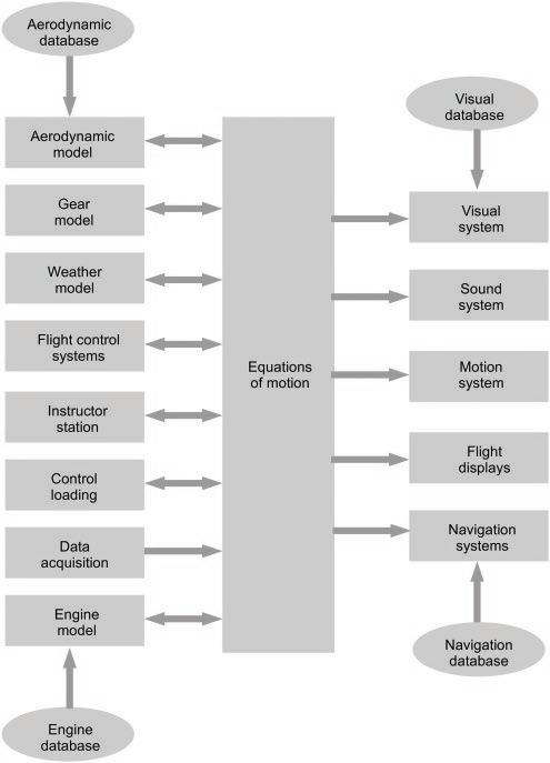
The structure of the majority of flight simulators is shown in Figure 1.1. Although this is a hardware diagram of modules and interconnections, it can also be viewed as a model of the software modules and interfaces. The main modules are shown as rectangles and the databases are shown as ellipses. Note the direction of the arrows, implying that some modules generate data for the equations of motion, whereas others use data produced by the equations of motion. The most significant point of this diagram is that the equations of motion module is the focal point of the simulator and is connected to all the other modules.
Although the use of flight simulators in civil and military training differs considerably from flight simulators used in engineering research, the core software is common to most flight simulators. The major variation is the number of visual channels and methods of projection. Invariably, the motion platform is omitted in an engineering simulator and is usually replaced with a G-cueing seat in military simulators (White, 1989).
The modules are shown as individual systems, but many comprise sub-systems specific to the module function. Note also that the term database is not used in the common usage used in computing; rather, they are databases containing data that is specific to a module and, in this sense, they are application-specific files loaded when the simulation starts.
From a modelling perspective, the equations of motion module is the core of the simulator. It contains the state of the simulation, updates the aircraft dynamics at the frame rate of the simulator and acquires the inputs to compute the forces and moments applied to the vehicle. In turn, the forces and moments are used to compute the accelerations, velocities and positions of the vehicle. Often these equations are referred to as six-degree-of-freedom (or 6-DOF) equations because they compute the linear state of the vehicle in three axes and the rotary state of the vehicle in three axes. The equations of motion module is also responsible for transforming forces, accelerations, velocities and position between axes, to provide the simulator state data in an appropriate form for the various modules. Generally, the equations of motion are applicable to any form of aircraft, where the aircraft-specific information is retained in the aerodynamic model, the gear model and the engine model.
The aerodynamic model contains information to compute the aerodynamic forces and moments of the airframe, which is unique to a particular aircraft. For many aircraft, the database is provided by the manufacturer and contains the aerodynamic data for the aircraft for the complete flight envelope in all configurations. In addition to the aerodynamic data, it includes test data used to validate the simulation. The quality of the flight model is dependent on the quality of the flight data, and during qualification of a simulator, the performance and handling of the simulated aircraft will be compared with the validation data provided for the simulator.
The gear model is a mechanical model of the undercarriage assembly of the aircraft, in particular the springs, oleos (dampers), brakes and tyres. During the take-off and landing roll and taxiing, the
interaction between the rudder pedals, toe brakes and tiller results in forces and moments in the undercarriage assemblies, which are transformed to the aircraft frame. The models will include tyre scrubbing and scuffing, brake fading and overheat and possibly tyre burst. As the take-off and landing are critical phases of flight, the gear model is an important component of simulation and extensive tests of take-offs and landings are undertaken during qualification of a flight simulator. As temperature, pressure and density of air in the troposphere vary with altitude, these parameters must be modelled correctly. Air temperature affects engine performance, aerodynamic performance varies with air density and air pressure is used in the air data computer computations and flight instruments. In addition, a weather model provides winds, from either meteorological data or a generic model, turbulence, microburst data, precipitation (used in modelling weather radar) and wind shear.
Figure 1.1 Structure of a Flight Simulator.
A modern civil transport aircraft has a flight management system (FMS) and flight control systems (FCS) to provide automatic modes to aid navigation. In a flight simulator, these systems are simulated to enable flight crews to operate the equipment in exactly the same way as the aircraft. The FMS commands the FCS, which drives the primary aircraft flight controls to manage airspeed, altitude, rate of descent and heading. The response of the FCS must match the aircraft systems very closely and, in some cases, an avionics database is also provided for the FMS and FCS.
A flight simulator for a civil transport aircraft used for pilot training will be managed by an instructor who sets flight conditions, introduces failures, monitors pilot performance and provides debriefing for flight crews. In a civil simulator, the instructor is positioned towards the back of the flight deck at the instructor operating station (IOS) and is provided with a screen to monitor the aircraft track, enter settings and introduce environmental conditions, typically via menu selection. The role of the simulator instructor is very important – they monitor the flight crew operations closely, to intervene as part of instruction but not to interfere with operations in an unnatural way. The design of the IOS and its capability can influence the quality of instruction considerably. Although there is no official standard for instructor station design, most modern instructor stations are very similar in terms of their capabilities and user interface.
In an aircraft, the aerodynamic loads on control surfaces vary with airspeed and acceleration and this dynamic loading of the primary controls is achieved in flight simulators by means of hydraulic or electrical actuation. In addition, the throttles and trim wheel may also be driven by an actuator, typically a servo-motor. The response of the control loading system, which is a dedicated system on most flight simulators, is much faster than the main frame rate. A major concern with active controls is the safety of the flight crew being physically close to active controls and safety interlocks are provided in both hardware and software to ensure that the movement of the controls cannot cause harm to a pilot as a result of inadvertent activation.
For the engine model, the manufacturer will provide detailed data of engine performance and engine dynamics. A modern turbofan engine includes a full authority digital engine control (FADEC) system and details of its operation are also provided in the data package. In addition to the provision of data to compute thrust, RPM, fuel flow and engine temperatures, the starting and shutdown procedures (both on the ground and in flight) must be modelled correctly, in order to introduce engine-start problems and to ensure flight crews have a full understanding of engine operation to cope with partial and full engine failures. The engine model is a combination of thermodynamics (gas flows) and the dynamics of turbomachinery rotating at very high speeds. Much of this data is proprietary and licensed to the airline operating the simulator.
A flight simulator may have several hundred wires connecting the levers, knobs, selectors, switches and controls. These connections are a combination of analogue and digital inputs which must be acquired every frame. Often dedicated input/output (I/O) hardware is provided to capture input signals at high data rates and with sufficient resolution. The actual sampling and conversion may take several microseconds per signal and consequently, special-purpose hardware is used for data acquisition with high bandwidth transfers to the memory of the simulator computers, in order to minimise delays associated with data acquisition.
In a modern flight simulator, three or four independent image generators (IGs) render the external scene viewed from the flight deck or cockpit. The actual scenery is stored in a visual database and loaded by each IG at run-time. The scene is typically formed from millions of coloured and textured triangles and the IG performs 3D graphics operations to display these images at 50 frames per second (fps) (or higher) with resolutions approaching 2000 × 2000 pixels per channel. The images are projected, merged and blended to form a continuous wrap-around display of scenery which includes dynamic entities. The conditions displayed by the IGs should match the weather
conditions, varying from thick fog to perfect visibility, and produce lighting according to the (simulated) time of day. A considerable amount of development goes into the production of detailed databases for airports and terrain, and real-time 3D graphics algorithms ensure highly detailed images are rendered at the visual system frame rate.
In addition to providing visual cues, sounds that are audible in flight need to be replicated in a flight simulator. Nowadays, the accepted method of sound generation is to carefully record sounds on the flight deck and then play back these sounds using a sound card which generates a sound signal from data stored in a buffer in a recognised format, for example, a wav file. Fortunately, most of the requirements for sound generation are met by the capabilities of modern sound cards. Typically, a database of sounds is accessed to generate sounds appropriate to the flight conditions.
Many of the accelerations on the human body occurring in flight are very different from everyday movement and motion cues in a simulator are matched to visual cues to emphasise the sense of motion in a simulator. This is achieved in simulation by attaching the flight deck to six hydraulic (or, more recently, electrical) linear jacks, which move independently in order to replicate the three linear movements and the three angular rotations. The main problem is that the length of movement of the jacks is of the order of 2 m and there is an inevitable difference between motion perceived in an aircraft and motion in the simulator, which cannot be sustained. Nevertheless, for pilot training, a motion platform is a requirement for the qualification of full flight simulators. For engineering flight simulators, the motion platform is usually omitted on the basis that it contributes little to the design and testing of aircraft systems.
Modern military and transport aircraft have flat screen displays, known as electronic flight instrument systems (EFIS) rather than the mechanical instruments used in smaller aircraft. In flight simulation, it is possible to use 2D computer graphics to emulate EFIS displays. The difficulty with emulation is to ensure that the frame rate is maintained at all times. An option is to use actual aircraft displays and generate the appropriate inputs but, invariably, this is a far more expensive solution.
Finally, navigation is an essential part of aircraft operations and, in simulation, the aircraft may fly several thousand miles using en-route navigation and guidance from radio transmitters, satellites and inertial sensors. The operation of the navigation equipment and alignment of worldwide radio aids with aircraft routing must be accurate to the tolerances of airborne navigation. The navigation database contains all the beacon locations, frequencies and ranges, runway layouts and information that is loaded into an FMS, including airways and departure and arrival information (SIDs and STARs). In addition, failure modes must also be simulated correctly.
This brief description of a typical flight simulator outlines the modules and their functions. There is no unique organisation of a modern flight simulator. Nevertheless, these modules are common to most flight simulators and the software used in these modules is designed to meet the requirements of each module. Once the overall structure is determined, consideration can be given to the design of the software structures, in particular to establish the inputs required by software modules and their connection to the simulator computers.
1.3 Real-time Flight Simulation
1.3.1
The Concept of Real-time Computing
Most programs and applications running on computers are captured as source code written in a high-level language, compiled to machine instructions, linked with relevant libraries and then loaded into memory and executed. For most users, the emphasis is on correctness rather than
performance. For example, in computational fluid dynamics, the computation of flow fields may take several hours and the speed of execution is mainly influenced by the efficiency of the compiler and the speed of the processor (or cores). In other applications, particularly where there is human interaction with the software, performance is a major consideration.
In the 1980s, several vendors produced flight simulator games for home computers. Many experienced pilots found these programs to be much harder to fly than airline simulators or the actual aircraft. The controls were flimsy and the PC screens were small but the main criticism was the speed of the PC graphics hardware to update the displays, particularly the external view. The games developers traded off visual fidelity (realism of the displays) for the frame rate to the extent that many games updated at only 3–5 fps, causing pilots to over-control their inputs. From an engineering perspective, this was a well-known problem in sampled-data theory.
There are many examples of systems that must meet tight timing constraints, which are referred to as real-time systems. A system is a real-time system if the inputs are captured and responded to within a defined time. For example, a computer in a bottling factory may be required to detect the position of a bottle on a conveyor belt, select a cap and actuate a mechanism to secure the cap to the bottle within one-tenth of a second. This repetitive process must be guaranteed to apply a cap within 100 ms, at all times and under all conditions, and the software will be validated to ensure that the real-time requirement is fully met.
The situation just outlined is also common in flight simulation. The positions of the flight controls and the various levers, knobs and switches are acquired, the equations of motion are computed for the airframe and the engines, and the results are output as computer graphics on displays and possibly to actuators to position the motion platform. A typical frame rate in real-time simulation is 50 Hz, giving a frame time of 20 ms. By completing the computations within this frame time, the perceived motion is smooth with no apparent discontinuities, the simulation of the dynamics is computed to an acceptable accuracy and the sampling rate is matched to the time constants of the flight dynamics.
There is one significant difference from the industrial example – the pilot interacts with the software. In a flight simulator, the pilot acquires information from the simulator displays and responds to move the inceptors. The delay resulting from acquiring visual information, cognitive processing and actuating muscles in the hands, arms and legs is of the order of 0.2 s (McRuer, 1995). At 50 Hz, a pilot will probably not detect any discontinuities or irregularities in the perceived motion of a transport aircraft but, with the simulation of agile fighter aircraft, the time constants of the dynamics may be much smaller, necessitating a faster frame rate. Similarly, hydraulic actuation of a motion platform may necessitate an update rate in excess of 1000 Hz to ensure smooth (and indiscernible) movement of the platform.
In real-time software, the time to respond to an input event must be guaranteed at all times (Burns and Wellings, 2001). However, synchronisation and timing of code in high-level languages are mostly provided by operating system functions. This distinction is important because responsibility for the real-time response is delegated to the operating system rather than user software, ensuring that:
● the operating system is responsible for the interface with hardware devices, providing optimal performance of data transfers;
● transfers and errors are managed in a clear and consistent manner;
● the operating system decides the order and priority of accesses to external devices.
The major constraint in a real-time system is that there is a finite number of instructions that can be executed during one frame. Consequently, in real-time systems, emphasis is focused on the
speed of executing software, and advances in processor architecture have benefited flight simulation considerably:
● Processor cycle times have reduced from several microseconds to tens of nanoseconds over the last 20 years or so.
● Modern processors contain multiple cores operating in parallel. In applications where parallel streams can be identified and allocated to specific cores, considerable gains in processing speed are achievable.
● Instruction caches allow pending instructions to be fetched while the processor is executing the current instruction; fetching an instruction from the cache is much faster than fetching instructions from memory (Wilkinson, 1996). However, when functions are called or there is a jump in the execution path of the code, the instruction caching restarts.
● Similarly, data caches are used to pre-fetch data from memory so that frequently accessed data is available in the cache rather than via memory. When the region of accessed data changes, the data caching restarts.
● Direct memory access (DMA) allows data to be transferred between memory and external devices while the processor is executing instructions. The processor is responsible for initiating the transfer and responding to the completion of the transfer but the processor executes instructions in parallel with DMA transfers.
● Modern compilers generate code that is optimised for specific instruction sets and register sets of a processor, significantly increasing processing speeds as variables are mostly accessed via machine registers rather than memory.
However, these advances do not ensure the real-time requirement to complete operations within a frame; they enable more computing to be completed during the frame. The performance of the operating system in a real-time system is as important as the performance of the user code.
1.3.2 Operating Systems
A main role of an operating system is to facilitate data transfers between applications and external devices. The user interface is simplified because the user software needs no detailed knowledge of the hardware, the software interface is well-defined and much of the software interface is common to all devices. Typically, transfers comprise five stages:
1) Establishing linkage to the hardware.
2) Setting the device to perform specific transfers, for example, the direction of the transfer and the number of bytes of data to transfer.
3) Initiating a transfer.
4) Completing the transfer, particularly to establish if the transfer succeeded.
5) Closing the linkage to the hardware.
Stages 2–4 enable transfers to be repeated while the device is, in effect, connected to the user software. Between stages 3 and 4, while a transfer is under way, the processor executes other instructions rather than simply waiting for the completion of the transfer. The occurrence of stage 4 is normally an interrupt, where the processor stops its current process in order to respond to the interrupt, checking the status of the transfer and possibly initiating another transfer.
This sequence of events is common to all operating systems. For example, in a desktop computer, file transfers to the hard drive are performed by establishing a channel between an area of user memory and a region of the hard drive, defining the size of the data to be transferred and the