AnIntroductiontoSystem ModelingandControl
JohnChiasson
BoiseStateUniversity Boise,Idaho UnitedStates
Thiseditionfirstpublished2022 c 2022JohnWiley&Sons,Inc.
Allrightsreserved.Nopartofthispublicationmaybereproduced,storedinaretrievalsystem,ortransmitted, inanyformorbyanymeans,electronic,mechanical,photocopying,recordingorotherwise,exceptas permittedbylaw.Adviceonhowtoobtainpermissiontoreusematerialfromthistitleisavailableat http://www.wiley.com/go/permissions.
TherightofJohnChiassontobeidentifiedastheauthorofthisworkhasbeenassertedinaccordancewithlaw.
RegisteredOffice
JohnWiley&Sons,Inc.,111RiverStreet,Hoboken,NJ07030,USA
EditorialOffice 111RiverStreet,Hoboken,NJ07030,USA
Fordetailsofourglobaleditorialoffices,customerservices,andmoreinformationaboutWileyproductsvisit usatwww.wiley.com.
Wileyalsopublishesitsbooksinavarietyofelectronicformatsandbyprint-on-demand.Somecontentthat appearsinstandardprintversionsofthisbookmaynotbeavailableinotherformats.
LimitofLiability/DisclaimerofWarranty
Thecontentsofthisworkareintendedtofurthergeneralscientificresearch,understanding,anddiscussiononly andarenotintendedandshouldnotberelieduponasrecommendingorpromotingscientificmethod, diagnosis,ortreatmentbyphysiciansforanyparticularpatient.Inviewofongoingresearch,equipment modifications,changesingovernmentalregulations,andtheconstantflowofinformationrelatingtotheuseof medicines,equipment,anddevices,thereaderisurgedtoreviewandevaluatetheinformationprovidedinthe packageinsertorinstructionsforeachmedicine,equipment,ordevicefor,amongotherthings,anychangesin theinstructionsorindicationofusageandforaddedwarningsandprecautions.Whilethepublisherand authorshaveusedtheirbesteffortsinpreparingthiswork,theymakenorepresentationsorwarrantieswith respecttotheaccuracyorcompletenessofthecontentsofthisworkandspecificallydisclaimallwarranties, includingwithoutlimitationanyimpliedwarrantiesofmerchantabilityorfitnessforaparticularpurpose. Nowarrantymaybecreatedorextendedbysalesrepresentatives,writtensalesmaterialsorpromotional statementsforthiswork.Thefactthatanorganization,website,orproductisreferredtointhisworkasa citationand/orpotentialsourceoffurtherinformationdoesnotmeanthatthepublisherandauthorsendorse theinformationorservicestheorganization,website,orproductmayprovideorrecommendationsitmay make.Thisworkissoldwiththeunderstandingthatthepublisherisnotengagedinrenderingprofessional services.Theadviceandstrategiescontainedhereinmaynotbesuitableforyoursituation.Youshouldconsult withaspecialistwhereappropriate.Further,readersshouldbeawarethatwebsiteslistedinthisworkmay havechangedordisappearedbetweenwhenthisworkwaswrittenandwhenitisread.Neitherthepublisher norauthorsshallbeliableforanylossofprofitoranyothercommercialdamages,includingbutnotlimitedto special,incidental,consequential,orotherdamages.
LibraryofCongressCataloging-in-PublicationData
Names:Chiasson,John,author.
Title:Anintroductiontosystemmodelingandcontrol/JohnChiasson. Description:Firstedition. | Hoboken,NJ:JohnWiley&Sons,Inc.,2022. | Includesbibliographicalreferencesandindex. Identifiers:LCCN2021030670(print) | LCCN2021030671(ebook) | ISBN 9781119842897(cloth) | ISBN9781119842903(adobepdf) | ISBN 9781119842910(epub)
Subjects:LCSH:Systemsengineering–Mathematics. | Mathematicalmodels. Classification:LCCTA168.C552022(print) | LCCTA168(ebook) | DDC 620.001/171–dc23
LCrecordavailableathttps://lccn.loc.gov/2021030670
LCebookrecordavailableathttps://lccn.loc.gov/2021030671
CoverDesign:Wiley
CoverImage:c ByWalterBarie
Setin10/12ptComputerModernRomanbyStraive,Chennai,India
10987654321
Prefaceix AbouttheCompanionWebsitexiv 1Introduction1
1.1Aircraft...................................1
1.2Quadrotors.................................7
1.3InvertedPendulum............................12
1.4MagneticLevitation............................13 1.5GeneralControlProblem.........................15
2LaplaceTransforms17
2.1LaplaceTransformProperties......................20
2.2PartialFractionExpansion........................24
2.3PolesandZeros..............................35
2.4PolesandPartialFractions........................36 Appendix:ExponentialFunction.....................39 Problems..................................43
3DifferentialEquationsandStability49
3.1DifferentialEquations...........................49
3.2PhasorMethodofSolution........................52
3.3FinalValueTheorem...........................57
3.4StableTransferFunctions.........................62
3.5Routh–HurwitzStabilityTest......................65 Problems..................................77
4Mass–Spring–DamperSystems89
4.1MechanicalWork.............................89
4.2ModelingMass–Spring–DamperSystems................90
4.3Simulation.................................96 Problems..................................100
5RigidBodyRotationalDynamics111
5.1MomentofInertia.............................111
5.2Newton’sLawofRotationalMotion...................112
5.3Gears....................................120
5.4RollingCylinder..............................127 Problems..................................135
6ThePhysicsoftheDCMotor149
6.1MagneticForce..............................149
viContents
6.2Single-LoopMotor.............................151
6.3Faraday’sLaw...............................155
6.4DynamicEquationsoftheDCMotor..................163
6.5OpticalEncoderModel..........................165
6.6TachometerforaDCMachine*.....................168
6.7TheMultiloopDCMotor*........................170 Problems..................................175
7BlockDiagrams185
7.1BlockDiagramforaDCMotor.....................185
7.2BlockDiagramReduction.........................187 Problems..................................197
8SystemResponses203
8.1First-OrderSystemResponse.......................203
8.2Second-OrderSystemResponse.....................205
8.3Second-OrderSystemswithZeros....................217
8.4Third-OrderSystems...........................222 Appendix:RootLocusMatlabFile...................224 Problems..................................224
9TrackingandDisturbanceRejection233
9.1Servomechanism..............................233
9.2ControlofaDCServoMotor.......................239
9.3TheoryofTrackingandDisturbanceRejection.............252
9.4InternalModelPrinciple.........................256
9.5DesignExample:PI-DControlofAircraftPitch............258
9.6ModelUncertaintyandFeedback*....................265 Problems..................................273
10PolePlacement,2DOFControllers,andInternalStability285
10.1OutputPolePlacement..........................285
10.2TwoDegreesofFreedomControllers...................298
10.3InternalStability.............................308
10.4DesignExample:2DOFControlofAircraftPitch...........316
10.5DesignExample:SatellitewithSolarPanels(CollocatedCase)....321 Appendix:OutputPolePlacement....................324 Appendix:MultinomialExpansions...................328 Appendix:Overshoot...........................329 Appendix:UnstablePole-ZeroCancellation...............335 Appendix:Undershoot..........................336 Problems..................................339
11FrequencyResponseMethods361
11.1BodeDiagrams..............................361
11.2NyquistTheory..............................383
11.3RelativeStability:GainandPhaseMargins...............402
11.4Closed-LoopBandwidth.........................409
11.5LeadandLagCompensation.......................414
11.6DoubleIntegratorControlviaLead-LagCompensation........419
11.7InvertedPendulumwithOutput Y (s)= X (s)+ + J m θ (s)....426
Appendix:BodeandNyquistPlotsinMatlab.............427 Problems..................................428
12RootLocus447
12.1AngleConditionandRootLocusRules.................449
12.2AsymptotesandTheirRealAxisIntersection..............457 12.3AnglesofDeparture............................463
12.4EffectofOpen-LoopPolesontheRootLocus.............481 12.5EffectofOpen-LoopZerosontheRootLocus.............482 12.6BreakawayPointsandtheRootLocus..................483 12.7DesignExample:SatellitewithSolarPanels(Noncollocated).....484 Problems..................................488
13InvertedPendulum,MagneticLevitation,andCartonaTrack497 13.1InvertedPendulum............................497 13.2LinearizationofNonlinearModels....................506 13.3MagneticLevitation............................510
13.4CartonaTrackSystem..........................516 Problems..................................521
14StateVariables537
14.1StatespaceForm..............................537 14.2TransferFunctiontoStatespace.....................539 14.3LaplaceTransformoftheStatespaceEquations............551 14.4FundamentalMatrixΦ..........................554 14.5SolutionoftheStatespaceEquation*..................558 14.6DiscretizationofaStatespaceModel*..................561 Problems..................................563
15StateFeedback569 15.1TwoExamples...............................569 15.2GeneralStateFeedbackTrajectoryTracking..............578 15.3MatrixInversesandtheCayley–HamiltonTheorem..........579 15.4StabilizationandStateFeedback.....................584 15.5StateFeedbackandDisturbanceRejection...............589 15.6SimilarityTransformations........................593 15.7PolePlacement..............................598 15.8AsymptoticTrackingofEquilibriumPoints...............603 15.9TrackingStepInputsviaStateFeedback................605 15.10InvertedPendulumonanInclinedTrack*................612 15.11FeedbackLinearizationControl*.....................618 Appendix:DisturbanceRejectionintheStatespace..........623 Problems..................................626
16StateEstimatorsandParameterIdentification643
16.1StateEstimators..............................643
16.2StateFeedbackandStateEstimationintheLaplaceDomain*....660
16.3Multi-OutputObserverDesignfortheInvertedPendulum*......663
16.4PropertiesofMatrixTransposeandInverse...............665
16.5Duality*..................................668
16.6ParameterIdentification.........................669 Problems..................................677
17RobustnessandSensitivityofFeedback693
17.1InvertedPendulumwithOutput x ....................694
17.2InvertedPendulumwithOutput y (t)= x(t)+ + J m θ (t)......708
17.3InvertedPendulumwithStateFeedback................711
17.4InvertedPendulumwithanIntegratorandStateFeedback......715
17.5InvertedPendulumwithStateFeedbackviaStateEstimation....717 Problems..................................720
*Sectionsmarkedwithanasteriskmaybeskippedwithoutlossofcontinuity. References727 Index731
Preface
Quitehonestly,IneverthoughtIwouldwriteabookforafirstcontrolscourse.So,what happened?Well,inmyteachingcareerIhavetaughtoutofthetextbooksbyOgata[1], Kuo[2],Franklinetal.[3],andPhillipsandHarbor[4]withlecturenotestakenfromQiu andZhou[5]andGoodwinetal.[6].IdidfindmanygreatideasinthesetextsthatIdo use.1 However,Iwasalsodisappointedthatthemodelingwasnotdoneusingfirstprinciplesofphysics,butratherthemodelwassimplystatedwithoutaderivation.Toaddress thisImadeupmyownlecturenotesonrigidbodydynamics(Chapter5),DCmotors (Chapter6),andtheinvertedpendulumandmagneticlevitationsystems(Chapter13). Irealizethatmyemphasisondetailedmodelingmaybea“bug”tosome(ratherthan a“feature”)asstudentsfinditdifficultandittakesawayfromdoingcontrol“stuff”. However,asacolleagueofmineputit,studentsdevelopimportantinsightwhenthey understandwherethedynamicmodelscomefromandanylinearization,approximation, orsimplificationusedtoobtainthem.
Itseemedtomeearlyinmycareerthatteachingthefirstcontrolscourseseemedtobe moreaboutitstechniques,i.e.,manipulatingblockdiagrams,drawingrootlocus,Bode andNyquistplots,doingtheRouth–Hurwitztest,etc.YetIthinkthecourseshouldbe aboutmakingsomephysicalsystemdowhatyouwantittodosuchashavingarobot armrotate30◦ despitetheweightoftheobjectinitsendeffector,orensureamagnetic bearingmaintainsanairgapdespitevariousloadsonit,keepingapendulumrodpointing straightup,etc.Irecallacolleaguecommentingonalecturehegaveinwhichhereferred tothestandardunityfeedbackcontrollerblockdiagram(Figure1)andtoldtheclassthat thecontroller Gc (s)wastobedesignedsothat C (s) ≈ R(s). Astudentthensimplyasked whynotjustgetridoftheblocksandset C (s)= R(s)!Itseemsthatinteachingthe firstcontrolscourseweendupmanipulatingblockdiagramssomuchandsoeasilythat studentsgetlostintheabstractionnotunderstandingwhattheyrepresent.
Controlsysteminstandardblockdiagramform.
FiguressuchasFigure2onthenextpageareincludedtohelpthestudentsremember whatablockdiagramsrepresents.
Spendingthetimetododetailedderivationsofafewmodelshelpsthestudentto understandandrememberwhatthetransferfunctionmodelsrepresent.Asimilarconfusionarisesinthemodelingofdisturbances.Whenadisturbanceisshownontheblock diagrammodel,itistypicallyplacedasinputtothephysicalsystem.Forexample,one mighthavealoadtorqueonamotor,butintheblockdiagramthisdisturbance D (s)is modeledcomingintothemotorinput,whichisavoltage(Figure1).Iexplainhowthis loadtorqueismodeledasanequivalentvoltagedisturbancewhichhasthesameeffecton
1 ToparaphrasePicasso: Goodideasareinspired,greatideasarestolen!
Figure1.
To D/A Computer I/O board From encoder
PositioncontrolofaDCmotor.
theposition/speedoftherotorastheactualloadtorque.Thissortofunderstandingseems tobelostinthestandardmanipulationsofconvertingadifferentialequationmodelinto ablockdiagrammodel.Ofcourse,somegoodlaboratoryworkcanreallyhelptoclarify theseideasaswell.
Chapter1presentsaqualitativedescriptionoftheoperationofanaircraft,aquadrotor, aninvertedpendulum,andamagneticallylevitatedsteelballtomotivatetheneedfor modelingandcontrol.
Chapter2isastandardpresentationoftheLaplacetransformtheorywithanemphasis onpartialfractionsasawaytoconnectthetimedomaintotheLaplacedomain.
Chapter3ondifferentialequationsintroducesstabilitybygivingspecialattentiontothe finalvaluetheorem(FVT).Thisisimportantasitisusedoverandoveragaintodetermineasymptotictrackingand/ordisturbancerejectionofstepinputsbyshowingthe error e(t) → 0viatheFVTlims→0 sE (s)=0.Thischapteralsoexplainshowtochecka differentialequationforstabilityusingtheRouth–Hurwitztest.
Chapters4–6aremodelingchapters.Chapter4developsmass–spring–dampersystems andusesthemtointroducesimulationusingSimulink.Chapter5presentsrigidbody dynamicsappliedtogearsandrollingmotion.Chapter6onDCmotorsusesthefirst principlesofphysicstodeveloptheequationsthatmodelaDCmotorandexplainshow bothanopticalencoderandatachometerwork.
Chapter7onblockdiagramsisprettystandard.Itisemphasizedthatablockdiagram issimplya graphical representationoftherelationshipsbetweenthevarious(Laplace transformed)variablesofaphysicalsystem.Itisshownhowtorearrangeandsimplify themusingblockdiagramreductionwhichprovidesastraightforwardandsimplewayto manipulatealltheblockdiagramsconsideredinthetextbook.
Chapter8onsystemresponsesisalsoprettystandard.Theobjectivehereistomake connectionsbetweenthes-domainandthetimedomain.
Chapter9coversPIDcontrolthatisexplainedusingtheinternalmodelprinciple.It providestheunderstandingofwhythecontrollermusthaveanintegratortorejectconstant disturbanceswiththePandDparts(typically)neededtomaketheclosed-loopsystem stable.ItisveryimportanttoleavethestudentwithanunderstandingofwhyPIDcontrol worksinsomanyapplications.
AftercoveringChapters1–9onetypicallycoversrootlocus,Bode,andNyquisttofinish theterm.Thestudentsseemedtocatchontorootlocusjustfine,buttheapproachdidn’t seemthathelpfulin designing acontroller.Thatis,onehastoproposesomeformfora controller(seeminglyoutofthinair)andthenvaryasinglegaintoseeiftheclosed-loop polescanbemovedtoalocationthatresultsinagoodresponse.Atypicalexampleisto haveanopen-loopmodeloftheform G(s)= b s(s + a) ,proposeacontrolleroftheform
Figure2.
Gc (s)= K s + z s + p , andthendoarootlocustochoosethegain K sothetwo“dominant” polesoftheclosed-loopsystemresultinadesiredresponse.However,usingthiscontroller onecanactuallyplaceallthreeclosed-looppolesarbitrarily!Therootlocusmethodis thenusuallyfollowedbyteachingBodediagrams,Nyquistplots,andNyquiststability. InmyexperienceNyquisttheoryhasalwaysbeenharderforthestudentstograsp.After allthathardworkofunderstandingNyquisttheorythedesignofacontrollerusingthe Bodediagram(lead,lag,lead–lag,etc.)toobtaindesiredgainandphasemarginsisstill atrialanderrorapproach.Further,theconnectionbetweengainandphasemarginsto systemperformance(settlingtime,overshoot,etc.)isnotsodirect.Thisleavesthestudents withoutmuchconfidenceindesigningcontrollers.
Ratherthanproceedingdirectlytorootlocus,Bode,andNyquistafterPIDcontrol,my approachistofirstcoverChapter10onoutputpoleplacementandtwodegreeoffreedom (2DOF)controllers.Startingwithatransferfunctionmodel,thesemethodsprovidea straightforwardsystematicwaytodesignanoutputfeedbackcontrollertoachievetracking anddisturbancerejectionobjectiveswhileoftenbeingabletoalsoeliminateovershootin stepresponses.
BeforeIaddedthematerialofChapter10(poleplacementand2DOFcontrollers),the firstsemestercourseendedbycoveringBodeandNyquist(Chapter11)androotlocus (Chapter12).AftercoveringChapter10thereistypicallynotenoughtimeinonesemester toalsocoverChapters11and12.Consequently,InowcoverChapter11atthebeginning ofthesecondcourse.Nyquisttheoryisfundamentaltounderstandingrobustnessand sensitivityofcontrolsystems.Usingtheunityoutputfeedbackcontrollerfortheinverted pendulumdesignedinChapter10aNyquistanalysisispresentedtoshowthattheresulting stabilitymarginsaretoosmallforthiscontrolsystemtoworkinpractice.Thepointhere isshowthatthereismoretocontrolthanjustmakingtheclosed-loopsystemstable. Chapter17elaboratesontheseideas.
Chapter12isastandardpresentationofrootlocus.Itendswithanexampleshowing howtodesignanotchfilterthatcancelsoutstableopen-looppolesclosetothe jω axis andisalsorobustwithrespecttosmallperturbationsinthelocationofthesepoles.
Chapter13derivesthedifferentialequationmodelofaninvertedpendulum,amagneticallylevitatedsteelball,andacartonatrackusingfirstprinciplesofphysics.Itisshown howtoobtainlinearmodelsoftheinvertedpendulumandthemagneticallylevitatedsteel ball,aswellashowtocontrolthemusingthemethodsofChapters9and10.
Chapter14onstatevariablesgivestheelementarylinear(matrix)algebrabackground neededforthestatefeedbacktheoryofChapter15.
Chapter15onstatefeedbackstartsoutbygivingadetailedderivationofastatetrajectorytrackingcontrollerforthecartonthetracksystem.Thisisfollowedageneral approachtostatefeedbackforlinearstatespacemodelsincludingthedevelopmentof astatespacepoleplacementalgorithm.Also,basedontheinternalmodelprinciple,a detailedpresentationofadisturbancerejectionstatespacecontrollerforaservosystem(DC motor)isgiven.Animportantgoalhereistoshowthattrajectorytrackingaccomplished bytrajectorygeneration,poleplacement,andstateestimation(Chapter16)providesa systematicprocedurefordesigningfeedbackcontrollersinthestatespace.Thisistobe comparedwiththesystematicprocedureforpoleplacementintheLaplacedomaingivenin Chapter10.
Chapter16isonstateandparameterestimation.Stateestimation(stateobserver)is presentedas“whattodo”whenonedoesn’thavefullstatemeasurements.Anobserver ispresentedthatprovidesasmoothestimateofthespeedofamotorusingtheoutput
ofanopticalencoderincomparisontothenoisyestimatefoundbydifferentiationofthe encoder’soutput.Parameterestimationvialeast-squaresisexplainedbygoingthrough thedetailedcalculationstoestimatethemodelparametersofaDCmotor.
Chapter17discussesrobustnessandsensitivity.NyquisttheoryandtheBodesensitivity integralsareusedtomakethereaderawareofthefundamentalproblemsofcontrolling systemswhoseopen-loopmodelshaverighthalf-planepoles.Specifically,therobustness andsensitivityoffourdifferentstabilizingcontrollersfortheinvertedpendulumare considered:(i)outputfeedbackofthecartposition,(ii)outputfeedbackofalinear combinationofcartpositionandpendulumrodangle,(iii)fullstatefeedback,and (iv)outputfeedbackofthecartpositionfollowedbystateestimationandstatefeedback.
SupplementaryMaterials
Thereisa solutionsmanual fortheendofchapterproblemsandasetof slides foreach chapter.Further,thereisalsoacompletesetof Matlab/Simulink files fortheexamples andproblemsthatrequirethem.Theseareallavailableonthebook’scompanionwebsite providedbyWiley.
Prerequisites
Theprerequisitesforthisbookareelementarydifferentialequations,Laplacetransforms, andafreshman/sophomorecoursein(calculus-based)physics.Chapters14,15,and 16assumesomefamiliaritywithmatrixalgebra(matrixmultiplication,determinants, inverses,etc.).
Typicalcoverageinthefirstsemestercourse
Chapter1,Allsections
Chapter2,Allsections
Chapter3,Allsectionsexceptsubsections3.51and3.52
Chapter4,Allsections
Chapter5,Sections5.1through5.3
Chapter6,Sections6.1through6.4
Chapter7,Allsections
Chapter8,Allsections
Chapter9,Sections9.1through9.4
Chapter10,Sections10.1through10.3
Possiblecoverageinasecondsemestercourse
Chapter11,Allsections
Chapter12,Allsections
Chapter13,Sections13.1,13.2,andeither13.3or13.4
Chapter14,Sections14.1through14.4
Chapter15,Sections15.1through15.8
Chapter16,Section16.1
Chapter17,Sections17.1through17.3
LogicalDependenceoftheChapters
Thelogicaldependenceofthechaptersisgiveninthefigurebelow.
Acknowledgments
IwouldliketotakethisopportunitytothankDr.UriRogersformakingseveralvaluable suggestionstoimprovethemanuscriptaswellasforpointingouttyposinitsearlier versions.Thiswasgreatlyappreciatedbytheauthor.IalsowanttothankDr.MarcBodson forhishelpfulcommentsandintroducingmetoparameteridentificationinourworkon electricmachines.EarlyinmycareerProfessorEdwardKamenwasverysupportiveofme teachingtheintroductorycontrolscourseforwhichIamverygrateful.Iamindebtedto thelateProfessorBruceFrancisforhiscommentsandkindremarksonanearlyversion ofthismanuscript.IamalsogratefultoDr.AykutSaticiforhiscrucialhelpinthefinal stagesofthiswork.Iwanttoexpressmygratitudetotheanonymousreviewersofthe manuscriptwhoprovidedmanyconstructivecomments.JohnWiley&Sonsisgratefully acknowledgedforallowingmetoreusematerialfromChapter1ofmybook Modelingand High-PerformanceControlofElectricMachines [7].MyWileyeditorBrettKurzmanand hisproductionteamofSarahLemoreandDeviIgnasihaveturnedmymanuscriptinto apublishedbook.Thankyou!Finally,IwouldliketothankthemanystudentsIhave taughtforputtingupwiththevariousversionsofthistextbookinmanuscriptform. Anycomments,criticisms,andcorrectionsaremostwelcomeandmaybesenttothe authorat chiasson@ieee.org.
JohnChiasson
Introduction
Inthischapterwesimplywanttopresentsomeexamplesofphysicalcontrolsystems. Theintenthereistoshowwhyfeedbackcontrolisnecessaryandtogivethe“bigpicture” ofwhatmustbedonetocontrolphysicalsystems.
1.1Aircraft
Figure1.1isadrawingofasimplepropellerpoweredairplane.Therearefourforceson theairplane: lift whichisprimarilyprovidedbythewings, drag whichisbasicallywind resistance, thrust whichisprovidedbythepropeller,and gravity.
Figure1.1. Thefourforcesonanaircraft.
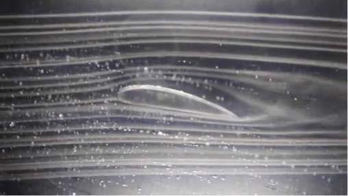
Liftisduetothedifferenceinairpressurebetweenthetopandbottomofanairfoil.The airfoilisagenerictermthatherereferstothewings,horizontaltailortheverticaltailof theaircraft.Figure1.2onthenextpageshowsstreamlinesofairmovingpastanairfoil (wing).Theairgoingoverthetoptravelsfaster(asitgoesagreaterdistance)thanthe aironthebottomofthewing.Becauseofthisspeeddifference,itturnsoutthattheair pressureonthetopofthewingisthenlessthantheairpressureonthebottomofthewing. Theresultingupwardforceiswhatwecall lift.Wecallliftan aerodynamic force.Figure1.3 onthenextpageshowstheairflowstreamlinesacrossanairfoilinawindtunnel.
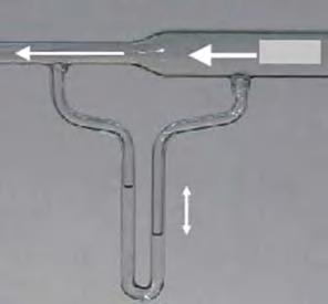
Thehorizontalcylindricalglasstube(Venturitube)inFigure1.4onthenextpageisused toexperimentallydemonstratethatairpressuredecreasesastheairspeedincreases.The originalflowofairfromtherightintheVenturitubeisforcedtoflowthroughabottleneck intoareduceddiametertube.Althoughnotobvious,atspeedsbelowsupersonic,airis
AnIntroductiontoSystemModelingandControl,FirstEdition.JohnChiasson. c 2022JohnWiley&Sons,Inc.Published2022byJohnWiley&Sons,Inc. Companionwebsite:www.wiley.com/go/chiasson/anintroductiontosystemmodelingandcontrol
Figure1.2. Aliftforceisduetotheshapeoftheairfoilthatresultsinthepressureabovetheairfoil beinglessthanthepressurebelowit.
Figure1.3. Airflowstreamlinesonawinginawindtunnel.Source:Screenshotfromhttp://www .decodedscience.com/how-does-an-airplane-fly-lift-weight-thrust-and-drag-in-action/5200.
Figure1.4. Venturitubeshowingairflowthroughabottleneckreducingthecross-sectionofthe tube.Inthissituationtheairisessentiallyincompressible.Sotheairspeedsupgoingthrough thebottleneckasthemassflowisconstant.The ∪-shapedtubebelowtheVenturitube(calleda manometer)isfilledwithwatertoshowthepressureontheleft-sideisreducedcomparedtothe pressureontheright-side.Source:ComputerGeezerandGeof[8].“Venturiflow”,https://commons .wikimedia.org/wiki/File:Venturi-Flow.png,2010,LicensedunderCCBY-SA3.0.
1.1Aircraft3 essentiallyincompressiblesohereitsdensityisthesameonbothsidesofthebottleneck.1 Thebottleneckresultsinincreasingtheairspeedasitgoesthroughit.Thatis,thesame massofairperunittimeisflowinginbothtubes(becausetheairdoesnotcompress)so itmustspeedupontheleftsideasthetubecrosssectionissmallerthere.The ∪-shaped columnsbelowtheVenturitubearefilledwithwater(calledamanometer)andshowthe experimentalfactthattheairpressureontheleftsideis less thantheairpressureonthe rightside.Asairspeedsupitspressuredrops!ThisisreferredtoasBernoulli’sprinciple. Thekeypointforairfoilsisthattheshapeofthewingcausestheairspeedonthetop ofthewingtoincreaseresultinginlowerpressureonthetopofthewingandtherefore producinglift.
TheleftsideofFigure1.5showsthecenterlineofthewingalignedwiththeairspeed v. Theairspeedissimplythespeedoftheaircraftwithrespecttotheair.Therightsideof Figure1.2showsthecenterlineofthewingatanangle α withrespecttotheairspeed. Aslongas α isnottoolarge(8to20degreesdependingontheplane),theliftforce increaseswith α.Wereferto α asthe angleofattack.
Let’sgobacktotheairplaneasshowninFigure1.6.The wings, horizontaltail,and verticaltail aregenericallyreferredtoas airfoils.The ailerons onthewings,the elevators onthehorizontaltail,andthe rudder ontheverticaltailarereferredtoas controlsurfaces
Propeller
Cock pit
Figure1.6. Theairfoilsandthecontrolsurfacesontheaircraft.
1 Anotherwaytosaythisisthattheairis not compressedgoingthroughthebottleneck.
Figure1.5. Angleofattack.
41Introduction
AsindicatedinFigure1.7,thecontrolsurfaceisconnectedbyahingetotheairfoil. Thepilotcanrotatethecontrolsurfaceaboutthehinge.AsshowninFigure1.7,ifthe controlsurfaceisrotateddown(relativetothecenterline)thentheairfoilwillpitchdown duetothe(aerodynamic)forceonthecontrolsurface.Conversely,ifthecontrolsurfaceis rotatedup,itwillcausetheairfoiltopitchup.
Control surface down causes airfoil to pitch down Airfoil
Aerodynamic force on control surface due to air flow Hinge
Control surface
Figure1.7. Controlsurfaceusedtopitchtheairfoilupordown.Withthecontrolsurfacedown,the airfoilpitchesdown.
ControlofPitchUsingtheElevators
Asafirstexampleofhowcontrolsurfacesareused,weconsidertheelevatorsonthe horizontaltail.Figure1.8showstheelevator(controlsurface)onthehorizontalwing rotatedup,whichresultsintheaircraftbeingpitchedupaboutitscenterofmass.By movingtheelevatorupordown,thepilotcancausetheaircrafttopitchupordown, respectively.
Pitch up
Usingtheelevatorstopitchtheaircraftup.
ControlofRollUsingtheAilerons
Figure1.9showstheaircraftwithitsleftailerondownanditsrightaileronisup.Theaerodynamicforcesonthetwoaileronsthencausetheairplanetorolltothepilot’sright.By adjustingtheangleoftheailerons,thepilotcanrollrightorleft.
ControlofYawUsingtheRudder
Thefinalcontrolsurfaceistherudderontheverticaltail.AsindicatedinFigure1.10,if thepilotrotatestheruddertotheright,thentheplanewillyaw(rotate)totherightand viceversa.
Elevator up
Horizontal tail
Vertical tail Rudder
Figure1.8.
Wing
Left aileron is down Roll
Wing
Usingtheaileronstorolltheaircraft.
Right aileron is up
Rudder deflection angle
Figure1.10. Usingtheruddertochangetheheadingoftheaircraft.
Figure1.9.
Yaw
Vertical tail
Rudder
ControllingtheAirplane
Thepilothasthefourinputcontrols:
(1) Theelevatortocontrolpitch.
(2) Theaileronstocontrolroll.
(3) Theruddertocontrolyaw.
(4) Anengineconnectedtoapropellertocontrolforwardthrust.
Figure1.11depictshowapilotinasmallairplanecontrolstheelevator,ailerons,and rudder.InFigure1.11thepilot’shandsareshownonthe yoke or centerstick (lookslike abitlikeacar’ssteeringwheel).Ifthepilotpullstheyoketowardhimself,theplanewill pitchupwhilealternativelypushingtheyokeawayfromhimselftheplanewillpitchdown. SeetheYouTubeanimationat[9].
Figure1.11. Pilotusingayoke,pedals,andthrottletocontroltheaircraft.Source:Courtesyof SteveKarp[9].“HowItWorksFlightControls”,October12,2013,https://www.youtube.com/ watch?v=AiTk5r-4coc.
Ifthepilotturnstheyoketotheright,theplanewillrolltotherightandconverselyif thepilotturnstheyoketothelefttheplanewillrotatetotheleft.
Figure1.11showsthepilotwitheachfootonapedal.Pushingontherightpedalthe planewillyawtotherightwhilepushingontheleftpedaltheplanewillyawtotheleft.
NotshowninFigure1.11isathrottle2 thatthepilotcanusetocontroltheenginespeed andthereforethepropellerthrust.
Theangularpositionoftheairplaneasspecifiedbyitspitch,roll,andyawisreferred toasthe attitude oftheaircraft.Thepilotusesthethrustinput(propeller)tomaintain airflowoverthewings.Ontakeoff,thepropellermustacceleratetheairplanetoaspeed suchthattheflowoftheairacrossthewingsisfastenoughtoproducethenecessary lift.Thepilotwillthenadjustthepitchangle(usingtheelevators)toobtainanangleof attackthatprovidesthenecessarylifttogettothedesiredaltitude.Duringtheclimbthe pilotmaybank(roll)andyawusingtheaileronsandrudder,respectivelytoheadoffin
2 Athrottlecontrolstheamountoffueltotheengine.
1.2Quadrotors7
thedirectionofthedestination.Atacruisingspeedatsomefixedaltitudethepropelleris primarilyproducingenoughthrusttocanceloutthedragforcesotheplanecanmaintain airspeed(andthereforetheliftforce).Thefirstaircraftrequiredalotofphysicaleffort onthepartofthepilottocontrolthemusingmechanicallinkagestomovethecontrol surfaces.However,usingtheseinputsthepilotcanmaketheairplanetakeoff,cruise,and landsafelyeventhoughtherearecrosswinds,airgusts,etc.disruptingtheplane’smotion.
AutomaticControl(Autopilot)
Thebasicideaof automaticcontrol istoreplacethehumanpilotwithanautopilot.The autopilotissimplyacomputerwithinputstoitbeingtheairspeed,theaircraftacceleration,andtheaircraftattitude(roll,pitch,andyawangles).Theautopilotobtainsthe airspeedmeasurementfroma Pitottube mountedontheoutsideoftheplane,theaccelerationfromathree-axisaccelerometersetmountedontheairplaneandtheangularrates fromathree-axisgyroscopesetalsomountedontheplane.Usingthesemeasurements,the autopilotcontinuously(typicallyeverymillisecond)determineswhatanglestherudder, elevatorsandaileronsshouldbeatinordertokeeptheplaneataproperattitudeaswell asthethrottlevaluesotheenginethrustisabletomaintaintherequiredairspeed.The autopilotsendsouttherequiredcontrolsurfacepositionstothecontrolsurfaceswhere motorsmovethesesurfacestothesecommandedvalues.Theautopilotalsosendsthe requiredthrottlevaluetotheenginewhereanothermotormaintainsthethrottleatthis value.Suchanautopilotcanmaintainlevelflightdespitewindgustsactingontheplane.
1.2Quadrotors
Figure1.12isapictureofaquadrotor,whichbasicallyconsistsoffourpropellersallin thesameplaneand90degreesapartconnectedtoamainbody.Byadjustingthespeedof eachpropelleronecancontrolthethrust(aerodynamicforce)producedbyeachpropeller. Thepropellerspeedsaremanagedbyanonboardmicroprocessorthatcontrolstheelectric motorofeachpropeller.
Figure1.12. PhotoofaParrot quadrotorinhover.Source:CourtesyofProfessorAykutSatici.
Firstlet’slookatasinglepropellerconnectedtoanelectricmotorasindicatedin Figure1.13.Forthepurposesofthisdiscussionthinkofthepropeller/motorsystemas beingonafrictionlesssurface.Thusthebottomofthemotorisfreetoslideorrotate withoutbeingstoppedbyanyfrictionfromthetable.
Conservationofangularmomentumrequires
Letthepropellerhaveamomentofinertia Jp aboutthespinaxisandthemotorhavea momentofinertial Jm aboutsameaxis.AsindicatedbythecurvedarrowsinFigure1.13, ifthepropellerrotatescounterclockwisethen ωp > 0,whileifthemotorrotatesclockwise then ωm > 0 Theangularvelocityofthepropellerisdenotedby ωp andithasangular momentum Lp = Jp ωp .Theangularvelocityofthemotorisdenotedby ωm andithas angularmomentum Lm = Jm ωm .Withnoexternalforcesactingonthemotor–propeller systemofFigure1.13,theprincipleof conservationonangularmomentum tellsusthatits totalangularmomentumisconstant,i.e. Lp + Lm =constant.Atstartupthepropelleris offandthemotorisstationarysothisconstantiszero.Afterturningonthepropellerwe mustcontinuetohave Lp + Lm =0or
Consequently,ifthepropellerisspinningcounterclockwisethemotormustspinclockwise. Typically Jp Jm so ωp ωm
Figure1.14isaschematicrepresentationofaquadrotorinflight.Theunitorthogonalvectors ˆ x e , ˆy e , ˆ z e representearth(inertial)coordinatesfixedtotheearth.3 ˆ z e points straightupfromtheearthwhile ˆ x e , ˆy e aretangenttotheearthandorthogonalto eachother.Wehave ˆ z e = ˆ x e × ˆy e so ˆ x e , ˆy e , ˆ z e formaright-handedcoordinatesystem. Let ˆ x b , ˆy b , ˆ z b beunitorthogonalvectorsattachedtothequadrotor(rigidbody)withtheir originatthecenterofmassofthequadrotor.Theunitvector ˆ x b pointstothefrontofthe quadrotor,theunitvector ˆy b pointstotheleftsideofthequadrotor,andtheunitvector ˆ z b pointsup(fromthepointofviewofthequadrotor).Notethat ˆ z b = ˆ x b × ˆy b sothat theyalsoformaright-handedcoordinatesystem. r cm isavectorfromtheoriginofthe
ˆ x e , ˆy e , ˆ z e coordinatesystemtothecenterofmassofthequadrotor,whichistheoriginof the ˆ x b , ˆy b , ˆ z b coordinatesystem.BothsetsofvectorsspanEuclidean3-space,whichwe denoteas E3
Figure1.15isaschematicofaquadrotorinhover,i.e., ˆ z b = ˆ z e withallthepropellers rotatingatthesameangularspeed ωp andthuseachproducingthesameupwardthrust (force) f where f = mg with m themassofthequadrator.NoteinFigure1.15thatthe frontandrearpropellersrotatecounterclockwise,whiletheleftandrightpropellersrotate
3 The“hat”overthevectorsistodenotethemas unit vectors.
Figure1.13.
1.2Quadrotors9
Left side of quadrotor
Front of quadrotor Thrust from propeller
Figure1.14. Quadrotorwiththeinertialandbodycoordinatesystemsshown.
Figure1.15. Ahoveringquadrotor.Thefrontandbackpropellersspincounterclockwise,whilethe leftandrightpropellersspinclockwise.
clockwise.Asaresultthetotalangularmomentum Lzb ofthefourpropellersaboutthe ˆ z b axisiszeroas
where Jzb isthemomentofinertiaofa propeller.As Lzb =0inhoverthebodyofthe quadrotormustalsohavezeroangularmomentumandthusitdoesnotrotateaboutthe ˆ z b axis.
Duetotheconstructionofthequadrotoritsthrustisalwaysinthedirectionofthe ˆ z b axis.Asaconsequence,thequadrotorbodymustberotatedtohaveacomponentofits thrustpointinthedirectionoftravel.Thisisdonebyroll,pitch,andyawmotions.
Figure1.16onthenextpageshowshowthequadrotorperformsa roll motion,thatis, rotatesaboutits ˆ x b axis.InFigure1.16 p denotestheangularvelocityofthequadrotor bodyaboutthe ˆ x b axis.Forthequadrotortorolltoitsrightthepropellerspeedonthe rightsideisdecreasedbyΔωp withaconsequentialdecreaseofΔf initsthrust,whilethe leftpropellerhasitsrotorspeedincreasedbyΔωp withanincreaseinitsthrustofΔf.
Figure1.16. Thequadrotorexecutingarollmotion.
Withthisapproachforrollingthequadrotorthetotalangularmomentum Lzb ofthefour propellersaboutthe ˆ z b axisiszeroas
Byconservationofangularmomentumthebodyofthequadrotordoesnotrotateabout the ˆ z b axisduringthisrollmotion.
Figure1.17showshowthequadrotorperformsa pitch motion,whichisarotationabout its ˆy b axis.InFigure1.17 q denotestheangularvelocityofthequadrotorbodyaboutthe ˆy b axis.Forthequadrotortopitchdownthepropellerspeedoftherearpropellerisincreased byΔωp withaconsequentialincreaseinitsthrustofΔf ,whilethefrontpropellerhas itsrotorspeeddecreasedbyΔωp withandecreaseinitsthrustofΔf. Withthiswayof pitchingthequadrotorthetotalangularmomentumofthefourpropellorsaboutthe ˆ z b axisiszeroas
Asinthecaseofarollmotion,duringapitchmaneuverthebodyofthequadrotordoes notrotateaboutthe ˆ z b axis.
Figure1.17. Thequadrotorexecutingapitchmotion.
FinallyFigure1.18showshowtogetthequadrotorbodytorotateaboutits ˆ z b axis, whichisreferredtoasa yaw motion.InFigure1.18 r denotestheangularvelocityofthe quadrotorbodyaboutthe ˆ z b axis.Forthequadrotortoyawtotheleft(counterclockwise
Figure1.18. Thequadrotorexecutingayawmotion. fromabove),thefrontandrearpropellerspeedsaredecreasedbyΔωp withaconsequential decreaseineachoftheirthrustsbyΔf ,whiletheleftandrightpropellershavetheirspeeds increasedbyΔωp withanincreaseintheirthrustsofΔf each.Incontrasttothepitch androllmotions,thetotalangularmomentumaboutthe ˆ z b axisofthefourpropellersis notzero.Specifically,theirtotalangularmomentumis
Lzb negativetellsusthatthenetangularmomentumofthepropellersisintheclockwise direction.Asangularmomentumisconserved,thebodyofthequadrotorwillrotatecounterclockwise(left).With Jb themomentofinertiaofthequadrotor body aboutthe ˆ z b axis itsangularmomentummustbe Lb = Jb r =4Jzb (Δωp )sothat Lb + Lzb =4Jzb (Δωp ) 4Jzb (Δωp )=0. Theangularvelocityofthequadrotorbodyisthen r =(4Jzb /Jb )Δ
AutomaticControl
Wecanconsidertheinputstothequadrotortobethefourpropellerspeeds.4 Typicallyaquadrotorhasaninertialmeasurementunit(IMU),whichconsistsofathreeaxis accelerometer,athreeaxisrategyro,andathreeaxismagnetometer.Thethreeaccelerometersprovidetheinertialacceleration(i.e.,theaccelerationwithrespecttotheearth)of thequadrotorinthe ˆ x b , ˆy b , ˆ z b directions.Thethreeaxisrategyrogivesangularvelocity vector(p,q,r )ofthequadrotorinthe ˆ x b , ˆy b , ˆ z b coordinatesystem.Thethreeaxismagnetometergivestheambientmagneticfield5 inthe ˆ x b , ˆy b , ˆ z b directions.UsinganIMUthere aremethodstoestimatetheorientationofthequadrotorrelativetotheearthcoordinate system(orientationof ˆ x b , ˆy b , ˆ z b withrespectto ˆ x e , ˆy e , ˆ z e )aswellasthevelocityvector ofthecenterofmassofquadrotorwithrespecttoearth.Basedonthequadrotor’sorientation,velocity,andposition,afeedbackcontroller(analgorithmonamicroprocessor) figuresouthowfasteachpropellershouldspintomakethequadrotorfollowareference trajectory.
4 Thereisan“inner”controllerthatcontrolsthepropellerspeedsbycontrollingthevoltageofthemotor connectedtothepropeller.
5 Sameastheearth’smagneticfieldiftherearenotpowerlinescloseby.
1.3InvertedPendulum
Aclassiccontrolprobleminacademiaistheinvertedpendulumonacart.Itconsistsof arodoflength whichisfreetorotateaboutapivotasshowninFigure1.19.Theidea istoapplytheappropriateforce u tothecarttokeepitunderthependulumrod,i.e.,to thekeeptherodvertical.Specifically,onecangetameasurementof θ and x (sayevery millisecond)andwantstodeterminethevalueof u (alsoeverymillisecond)thatkeeps thependulumatafixedpositionin x andkeeps θ =0.InChapter13wewillderivethe nonlineardifferentialequationsofmotionofthispendulum.Fornowwejuststatethem asfollows:
Thepointhereisthatforanyinput u(t)thesolutiontothesedifferentialequationsgives positionofthecart x(t)andtheangle θ (t)ofthependulumrod.
Figure1.19. Invertedpendulum.
Theseequationsmaylookcomplicated,butthatisonlybecausetheyare!Tosimplify themconsiderthesituationforwhich |θ | and | ˙ θ | = |dθ/dt| remainsmall.Thensin(θ ) ≈ θ, cos(θ ) ≈ 1, and
0sothatEqs.(1.7)and(1.8)canbeapproximatedbythe linear differentialequations
Inyourfirstdifferentialequationscourseyouprimarilystudied linear differentialequations. Thereasonforthisisthatweknowhowtosolvethem!Aswewillshowinlaterchapters,it isalsoknownhowto control aphysicalsystemwithalineardifferentialequationmodel.By thecontroloftheinvertedpendulumwemeanthatgiventhemeasurements x(t),θ (t)the inputvalue u(t)canbechosentokeepthependulumrodvertical.Ifthiscontrollerbased
1.4MagneticLevitation13
onthelinearmodelkeeps |θ | and | ˙ θ | small,thenthelinearmodelisavalidapproximation totheactualpendulumandthecontrollerwillalsoworkontheactualpendulum.
WecanuseLaplacetransformstoconvertlineardifferentialequationsinto algebraic equations.InChapters2and3wewilldoacomprehensivereviewofLaplacetransforms. FornowwejustnotethattheLaplacetransferfunctionmodeloftheinvertedpendulumis
ControlProblem
Thecontrolproblemistousethemeasuredvaluesof x(t)and θ (t)todeterminetheforce u(t)appliedtothecartsothatthependulumroddoesnotfall.Thecontrolalgorithmis simplyafunctionthatgivesthevalueof u(t)giventhevaluesof x(t)and θ (t).Acontroller canbedesignedusingtheabovetransferfunctionmodelortheabovedifferentialequation model.Inthefirsthalfofthebookwebasethecontroldesignonthetransferfunction model,whileinlaterchaptersofthebookadifferentialequationmodelisused.
1.4MagneticLevitation
Inthisexampleweconsideramagneticlevitationsystem.Theschematicgivenin Figure1.20showsawirewrappedaroundacylindricalcoreofironmakinganelectromagnet.
Figure1.20. Asimplemagneticlevitationsystem.
Applyingavoltage u(t)tothecoilresultsinacurrent i(t).Thiscurrentalongwiththe ironcoreproducesamagneticfieldthatextendsbelowtheelectromagnet.Thismagnetic fieldthenmagnetizesthesteelball,i.e.,makesitintoamagnet.Itturnsoutthatthe magneticforceofattractionbetweenthesteelballandtheelectromagnetisupwardand
proportionaltothesquareofthecurrentandinverselyproportionaltothesquareofthe distance.Mathematically,wewritethat Fmag = Ci2 /x2 where C isaconstant.Note inthefigurethatpositive x isdownwardand x =0correspondstothebottomofthe ironcore.
MathematicalModel
Therearecurrent-commandamplifiersthatallowonetohavetheamplifierputouta desiredcurrent.Usingsuchanamplifierwecanconsidertheinputtothemagneticlevitationsystemtobethecurrent i(t). Thedifferentialequationmodelofthismagnetic levitationsystemisthen(seeChapter13)
Here C istheforceconstant, m isthemassofthesteelball,and g istheaccelerationof gravity.Thisdifferentialequationmodelisimportantbecauseforanygiveninputcurrent i(t)tothecoil,thesolutionofthesedifferentialequationsthengivestheresponseofthe position x(t)andvelocity v (t)=˙x(t)ofthesteelball.Howeverthismodelisnonlinear. Asinthecaseoftheinvertedpendulum,wecanobtainanapproximatelinearmodel. Specifically,letthedesired(constant)positionofthesteelballbe x0 andchoosethe current i0 tomaketheball’saccelerationzero,i.e.,
WithΔx x x0 , Δ˙x ˙ x ˙ x
wewillshowinChapter13that
isavalid linear modelforΔx, Δ˙x, and u small.AfterstudyingChapter3youwillbeable toshowthatthecorrespondingLaplacetransformmodelis
Figure1.21isamagneticlevitationsystembuiltbyW.Barie[10].Itshowslightbeing shoneacrossthetopoftheballtoaphotodetectorsensor.Usingthissetuptheposition oftheballbeneaththeelectromagnetcanbefound.
ControlProblem
Basedonmeasurementsof x(t)and v (t),onewantstochoosetheinputvoltage u(t)sothe ballmaintainsafixedposition x0 belowtheelectromagnet,i.e.,itdoesnotfallnorgets suckedintothemagnet.Aproceduretochoose u(t)basedonthevaluesof x(t)and v (t) iscalledthecontrolalgorithmorcontroller.Thecontrolalgorithmisfoundusingeither thedifferentialequationmodelortheLaplacetransformmodel.