Hybrid Excited Synchronous Machines
Topologies, Design and Analysis
Yacine Amara
Hamid Ben Ahmed
Mohamed Gabsi
First published 2022 in Great Britain and the United States by ISTE Ltd and John Wiley & Sons, Inc.
Apart from any fair dealing for the purposes of research or private study, or criticism or review, as permitted under the Copyright, Designs and Patents Act 1988, this publication may only be reproduced, stored or transmitted, in any form or by any means, with the prior permission in writing of the publishers, or in the case of reprographic reproduction in accordance with the terms and licenses issued by the CLA. Enquiries concerning reproduction outside these terms should be sent to the publishers at the undermentioned address:
ISTE Ltd
John Wiley & Sons, Inc.
27-37 St George’s Road 111 River Street London SW19 4EU Hoboken, NJ 07030 UK USA
www.iste.co.uk
www.wiley.com
© ISTE Ltd 2022
The rights of Yacine Amara, Hamid Ben Ahmed and Mohamed Gabsi to be identified as the authors of this work have been asserted by them in accordance with the Copyright, Designs and Patents Act 1988.
Any opinions, findings, and conclusions or recommendations expressed in this material are those of the author(s), contributor(s) or editor(s) and do not necessarily reflect the views of ISTE Group.
Library of Congress Control Number: 2022943360
British Library Cataloguing-in-Publication Data
A CIP record for this book is available from the British Library
ISBN 978-1-78630-685-2
2.3.1.
2.3.2.
2.3.3.
2.4.
vi Hybrid Excited Synchronous Machines
2.4.1. Low-speed operations
2.4.2. Operation at high speeds/the notion of flux weakening
2.5. Operations on the entire “torque/speed” plane
2.5.1. Efficiency optimization algorithms on the entire “torque/speed” plane ................................
2.5.2. Normalized model with losses and the calculation of Vn max
2.5.3. Machines with non-salient poles (ρ = 1)
2.5.4. Machines with salient poles (ρ ≠ 1)
2.5.5. Validity of the tools developed and the contribution towards hybrid
2.6. Conclusions and
Chapter 3. Experimental Studies of Hybrid Excited
3.1.
3.2.
3.2.1.
3.2.2.
3.2.3.
3.3.
3.3.1.
3.3.2.
3.3.3.
3.4.
Foreword
Hybrid excited synchronous machines consist of two excitation sources, i.e. permanent magnets and field windings. Thus, they may have the synergies of both permanent magnet machines and wound field machines, most notably the high efficiency and high torque density of permanent magnet machines, and the flexible flux adjustment of wound field machines. There are many machine topologies of hybrid excited synchronous machines according to the allocation of permanent magnet and field winding excitations, series and parallel magnetic circuit hybridization, as well as two- and three-dimensional hybrid magnetic circuits. The introduction of field windings can help regulate the magnetic field and the output capability according to the working condition, which is beneficial for many applications, such as electric vehicles, with variable-speed requirements. Compared with the conventional permanent magnet machines, an extra flexibility can be used to adjust the flux linkage by the field excitation current. Consequently, higher torque at low speed, wider operating speed range, as well as high efficiency over a wide operating region can be obtained by employing appropriate control strategies. Hybrid excitation also provides a unique mitigation technique for an uncontrolled overvoltage fault at high-speed operation.
The authors of this book have been working on hybrid excited synchronous machines and control systems for many years. They have led the development of several novel hybrid excited synchronous machine topologies. The book is comprehensive in that it includes not only hybrid excited synchronous machines but also their control strategies. I am also very pleased to see the experimental investigation. Currently, hybrid excited synchronous machines still exhibit some challenges, such as complicated
structures and relatively low torque density. I am sure that this book will serve researchers, students and engineers very well in their further investigation for various applications.
Professor Zi-Qiang ZHU, Fellow
of Royal Academy of Engineering, Fellow of IEEE, Fellow of IET University of Sheffield, UK
Introduction
The increasing use of electrical energy in the functioning of our society, which is related to our transition towards clean and sustainable uses of energy, requires tools and methods to study electrotechnical objects to be developed to ensure their proper functioning for as long as possible. This means that we must have the tools required to understand their behavior, not just as one component, but also in the entire systems in which they can be found and throughout their life cycle, and therefore under any operating conditions.
As electromechanical conversion devices, electrical machines are at the heart of electrotechnical systems and energy conversion chains. At one extreme, they are used as a source of electrical energy (electrical generators), and at the other extreme, they are used to transform electrical energy into mechanical work (electric motors and actuators). These functions are performed very efficiently by such machines.
The purpose of this book is to provide electrical engineering students and researchers with the tools to analyze how synchronous machines operate over their entire field of operation.
In this book, particular emphasis is placed on these hybrid excited synchronous machines (HESMs). This HESM theme, although not a fundamental problem in the strict sense of the term, provides answers to problems which are no less fundamental: the flux weakening of permanent magnet machines, energy optimization and finally the increasing costs of rare-earth permanent magnets.
Among all the various types of electrical machines, permanent magnet synchronous machines are the most efficient when their operation does not require any flux weakening. This is due to the permanent magnets which produce an excitation flux with next to no losses. However, this powerful flux created by the magnets is a disadvantage when operating at high speeds because flux weakening is required.
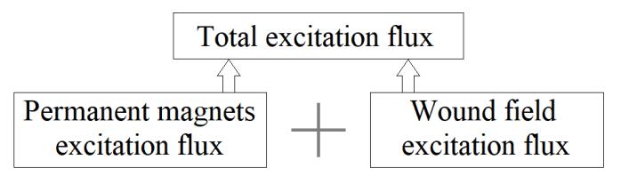
From a functional point of view, HESMs combine the advantages of permanent magnet machines (which have very high energy efficiencies) with those of electrically excited machines (which have an ease of operation along with variable speeds). In these machines, the total excitation flux is the sum of the flux created by the permanent magnets and the excitation flux created by the wound coils. This hybridization allows for greater flexibility for variable-speed operation and, in parallel, energy efficiency optimization for certain drives.
The authors have been working on HESMs for more than two decades, and this book is both a collection of their work and an update of the work done on drives based on synchronous machines (Lajoie-Mazenc and Viarouge 1991; Amara et al. 2009; Vido et al. 2011). It may be useful for both experienced researchers and students who wish to deepen their knowledge of synchronous machines.
The study of HESMs allows us to understand the behaviors of other families of synchronous machines. Permanent magnet synchronous machines can be considered as a special case of HESMs, where excitation coils are not used; electrically excited machines correspond to HESMs in which magnets are replaced by air; and finally, variable-reluctance synchronous machines correspond to HESMs in which the magnets are replaced by air, and wound field excitation is not used.
This book begins with a presentation of the principle of hybrid excitation for synchronous machines. The first chapter sets out the concept of what is meant by an HESM, placing them within the vast family of electrical machines. An up-to-date state of the art is presented, where the focus is on the HESM component. Different structures encountered in the scientific and technical literature are analyzed.
The second chapter is devoted to the behavior of HESMs when they operate as a motor. An original study of the behavior of these machines and
their environment is presented. It allows us to analyze the operation of HESMs, by taking their power supply into account (De Doncker et al. 2011). Electrical circuit models are used for this purpose. The purely analytical approach will be favored to determine the control quantities and the different control laws, according to the parameter sets used for the models. When the analytical approaches become too complicated to develop further, scripts that allow us to continue the analysis numerically will be made available to the reader. The behavior of the HESMs is analyzed over their entire operating range.
This book ends with a presentation of some structures that have been designed, realized and studied in our respective laboratories (SATIE and GREAH). This chapter illustrates the previous concepts and theoretical developments concretely.
We hope that this book will contribute to a better understanding of how HESMs function, and to the awakening of new ideas within our research laboratories.
Hybrid Excited Synchronous Machines: Principles and Structures
1.1. Introduction
Hybrid excited machines form a special class within that of synchronous machines. Hybrid excited synchronous machines (HESMs) are those in which two sources of excitation flux coexist (Figure 1.1): permanent magnets and excitation coils. Different terminologies (we will limit ourselves to terms in both English and French) have been used to describe this type of machine:
– hybrid excited (or excitation) synchronous machines (Machine synchrones à excitation hybride);
– double excitation synchronous machines or dual excitation synchronous machines (Machine synchrones à double excitation);
– combined excitation synchronous machines (Machines synchrones à excitation combinée);
– permanent magnet synchronous machines with auxiliary excitation windings (Machines synchrones à aimants permanents avec des bobinages d’excitation auxiliaires).
The aim of this combination is to combine the advantages of permanent magnet machines with those of electrically excited synchronous machines (Spooner et al. 1989; Levy 1997; Mizuno 1997; Hadji-Minaglou and
For a color version of all the figures in this chapter, see www.iste.co.uk/amara/hybrid.zip.
Henneberger 1999; Luo and Lipo 2000; Amara 2001). Figure 1.1 illustrates the principle of hybrid excitation, where the total excitation flux is the total sum of the contributions from the permanent magnets and the excitation winding.
Figure 1.1. Illustration of the hybrid excitation principle
The effective performance of these machines, in terms of operational flexibility at high speeds and their improved efficiency, has received a growing interest from researchers in both the academic and industrial worlds (Syverson 1995; Amara et al. 2004a, 2009; Akemakou 2006; Aydin et al. 2007; Mizutani et al. 2008; Reutlinger 2008; Wang 2009; Yu et al. 2009; Fang et al. 2010; Moynot et al. 2010; Wang et al. 2010; Xia et al. 2010; Xie and Xu 2010; Greif et al. 2011; Hoang et al. 2011; Pothi et al. 2015; Chao et al. 2018; Diao 2018; Liu et al. 2018).
In addition to this positive contribution towards synchronous machine operation, hybrid excitation also allows for flexibility in their design. Indeed, the adjustment of the two excitation sources constitutes an additional degree of freedom in this respect. This degree of freedom is formalized by a parameter, which we will call the hybridization rate α, and is defined by:
where Φe max is the maximum total excitation flux, and ΦPM is the permanent magnet flux linkage.
In motoring mode, these machines provide greater flexibility at high speeds and optimized energy efficiency (Amara 2001; Amara et al. 2004a, 2009; Pothi et al. 2015). In generating mode, hybrid excited
synchronous machines that are connected to a diode rectifier are an interesting alternative to permanent magnet machines associated with a controlled rectifier for high-speed operations (Amara et al. 2007). Moreover, in the current state of increasing costs for high-performance permanent magnets (rare-earth materials), as well as the negative ecological impact when extracting these rare-earth materials, the principle of hybrid excitation reduces the volume required for magnets in synchronous machines.
1.2. Interest in hybrid excitation
The work by Spooner et al. (1989) can be considered as one of the earliest academic contributions towards the topic of hybrid excited synchronous machines. However, it should be noted that patent applications were made much earlier (Rosenberg 1940; Shafranek 1967; Rosenberg 1968).
In the patent application (Shafranek 1967), the main claim concerned the provision of hybrid excitation to ensure the self-excitation of the alternators. Figure 1.2 shows the machine that was the subject of the patent. It should be noted that every source of magnetic flux, permanent magnets, excitation windings, as well as armature windings, are situated within the stator. It should be noted that not every structure illustrated in this chapter necessarily comes from a design.
The patent application by Rosenberg (1968), as well as the contribution from Spooner et al. (1989), discuss precisely what is meant by the principle of hybrid excitation as treated in this monograph. The authors express an interest in hybrid excitation as a means of controlling the air-gap flux. Moreover, the Spooner et al. (1989) authors point out the economic interest in reducing the volume used for permanent magnets.
In these previous two references (Rosenberg 1968 and Spooner et al. 1989), the authors emphasize the interest in controlling the air-gap flux obtained by the means of hybrid excitation, both for the motoring and the generating modes.
The contribution coming from hybrid excitation is illustrated in the following for both operational modes; in particular, the contribution from a functional viewpoint is emphasized.
Figure 1.2. Self-excited brushless alternator (Shafranek 1967)
1.2.1. Motoring mode operation
For motoring operational modes, the contribution from hybrid excitation is two-fold (Amara et al. 2019). First, it improves the flux weakening capability by controlling the total excitation flux. This allows for a broader operational range while maintaining a constant power, even for machines with a relatively low armature magnetic reaction field when compared to the excitation flux. A direct consequence of this is the possibility for the machine to operate with an effective power factor, which allows for a better dimensioning of the converter-machine assembly. Second, it improves the energy efficiency of the drive train.
To illustrate the first contribution, a simple theoretical development is presented in what follows: the framework for this development is the application of electric traction. It is based on the simplified hybrid excited machine model with smooth poles (no saliency), for which we ignore any losses and any magnetic saturation. We will return to this operational mode in more detail in Chapter 2.
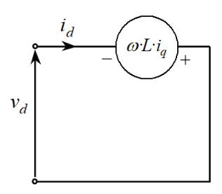
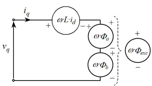
Figure 1.3 shows the equivalent electrical diagrams in the d- and q-axes of the “Park” frame of the first harmonic model with no loss, where:
– id, iq: d- and q-axis components of the armature current (A);
– vd, vq: d- and q-axis components of the terminal voltage (V);
– L: synchronous armature inductance (H);
– Фa: permanent magnet flux (Wb);
– Фb: wound field excitation flux (Wb);
– Фexc: total excitation flux (Wb);
– ω : electrical pulse (rad/s).
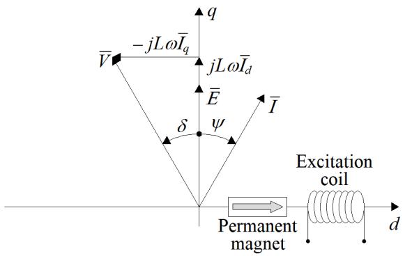
Figure 1.4 shows the vector diagram representing the main electromagnetic quantities (flux, EMF, voltage, current) defined in the “Park” reference frame. By convention, the angles ψ and δ, as they appear in this figure, are counted negatively and positively, respectively.
The armature flux linkage Фarm is the vector sum of the excitation flux Фexc, and the flux of the armature magnetic reaction ФAMR:
Despite being scalar quantities, it is possible to associate a vector to each flux, which in the framework of the first harmonic hypothesis is carried out using the axis corresponding to the spatial position at which each flux attains its maximum value. The excitation flux amplitude is given by:
a) d-axis equivalent electrical circuit
b) q-axis equivalent electrical circuit
Figure 1.3. Equivalent electrical circuits for non-salient hybrid excited synchronous machines (lossless model)
Having defined the two components for the armature flux linkage [1.2], it is interesting to distinguish between two terms that are often found in the literature: flux weakening and “de-excitation”. The first refers to the reduction of the total armature flux linkage, and the second to the reduction of the excitation flux. A flux weakening strategy may require de-excitation, and we will see in Chapter 2 that optimal flux weakening strategies do indeed often require de-excitation. The term “optimal” is used to describe any strategy that maximizes the torque or the power during high-speed operations.
Figure 1.4. Equivalent vector diagram for the lossless model of non-salient HESMs (motoring mode)
In this model, the modulus of the armature voltage and the value of the electromagnetic torque are, respectively, given by:
Equation [1.4] relates the armature voltage modulus V to that of the armature flux linkage Φarm and to the angular speed Ω . Equation [1.5] relates the electromagnetic torque Γem to the excitation flux modulus Φexc and to that of the armature current I. Here, p is the number of pole pairs.
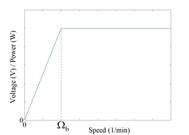
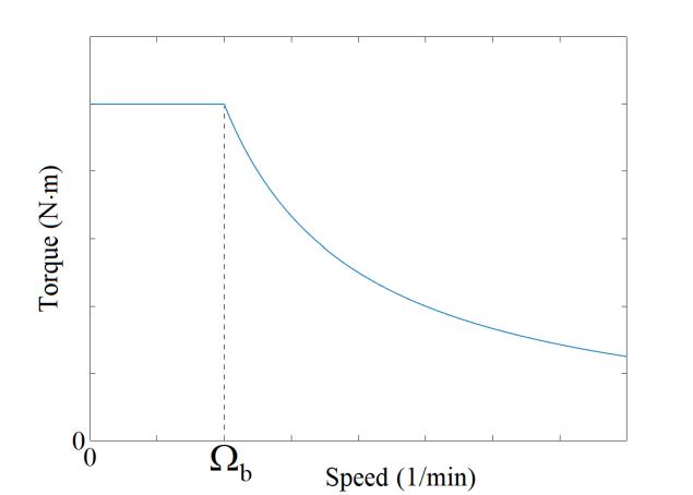
Figure 1.5 shows the characteristic envelopes of electrical drive specifications. Figure 1.5(a) shows the voltage, or power, characteristics as a function of the speed, and Figure 1.5(b) shows the torque characteristic.
The power has a characteristic whose shape is identical to that of the voltage. Below a certain speed, called the base speed Ωb, the torque must be as high as possible (Figure 1.5(b)). To impose the maximum amount of torque, the modulus of the excitation flux and the armature current, labeled Φexc max and Imax, respectively, should be as large as possible. The phase shift between the armature current and the open-circuit EMF must be zero (ψ = 0). In general, the maximum amplitude of the armature current is limited by thermal constraints.
a) “Voltage/speed” or “power/speed” envelope
b) “Torque/speed” envelope
Figure 1.5. “Voltage/speed”, “power/speed” and “torque/ speed” envelopes for electromechanical drives
By adopting this strategy, the modulus of the total armature flux linkage is constant, as well as the torque. They are given by:
It follows that the modulus of the armature voltage V varies linearly with the rotational speed:
With these equations, we gain a better understanding of why the voltage (power) and torque envelopes in Figure 1.4 have their shapes at low speeds (Ω ≤ Ωb).
However, from the base speed Ωb, which corresponds to the speed at which the maximum voltage is reached, the strategy for imposing the maximum torque no longer works. In order to operate above this speed, the total armature flux linkage must be reduced. It is therefore necessary to implement flux-weakening strategies.
The following equation gives the expression of the total armature flux linkage in the general case:
This shows that flux weakening can be achieved in several different ways. To reduce the flux, it is possible to adjust the modulus of the armature current I, its phase shift with respect to the EMF ψ or even the excitation flux Φexc. In the work by Amara et al. (2019), different strategies for weakening the flux have been studied. It was found that the best flux weakening strategy depends on the value of the normalized synchronous inductance Ln, which is defined by:
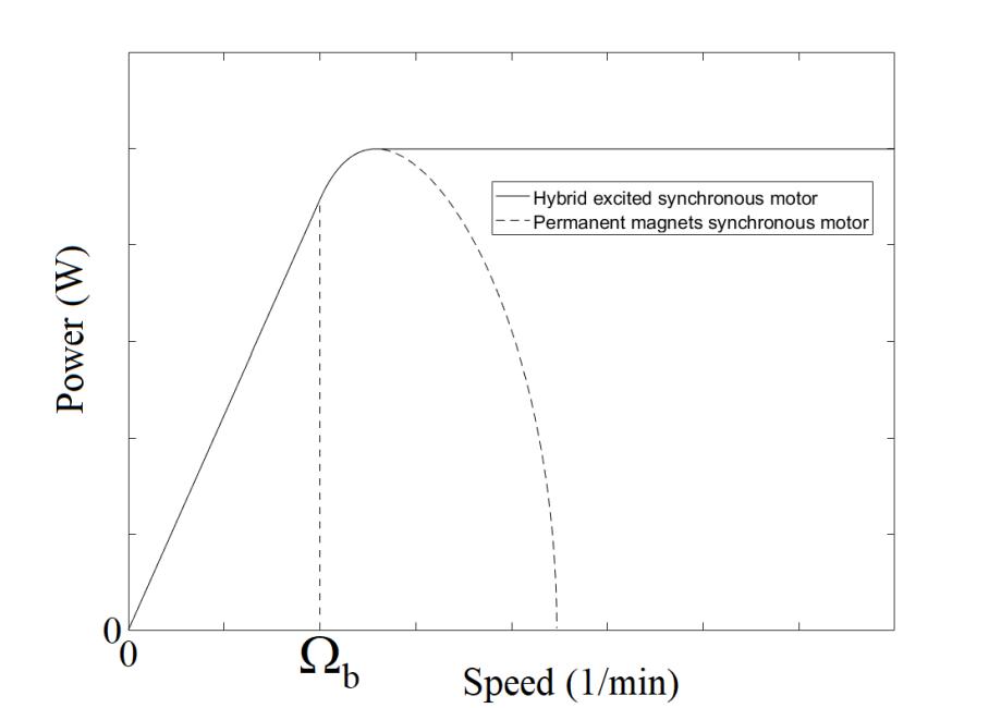
If the value of the normalized synchronous inductance is greater than or equal to unity, then extending the operational range beyond the base speed does not require the excitation flux to be controlled. The contribution coming from hybrid excitation towards the weakening of the flux is in this case nil. If, on the contrary, the value of the normalized synchronous inductance is less than unity, the contribution coming from the hybrid excitation towards the extension of the operational range is undeniable. Figure 1.6 shows the power characteristics for two machines with the same normalized inductance value which is less than unity (Ln = 0.5). One of them uses permanent magnet excitation while the other uses hybrid excitation. This figure illustrates the contribution coming from hybrid excitation.
From a sizing point of view, it is preferable to have a normalized synchronous inductance value less than unity, whenever this is possible. Having Ln < 1 allows for better sizing of the converter-machine assembly. The apparent power of the converter to be sized is closer to the maximum active power of the machine in this case. However, in order to avoid any electromagnetic limitations when broadening the operational range, the hybrid excitation must reduce the excitation flux, so that the minimum value of kf [1.3] is less than or equal to Ln
Figure 1.6. Power characteristics for a machine with Ln = 0.5, with and without hybrid excitation
This is one of the advantages of hybrid excitation, which allows the converter-machine assembly to be sized as accurately as possible, while still allowing the operational range to be extended beyond the base speed. We will return to the contribution from hybrid excitation for synchronous motors in more detail in Chapter 2.
1.2.2. Generation mode operation
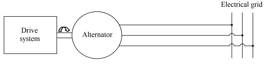
There are three different cases in which an alternator may be used in the operation of a synchronous machine. These are (Figure 1.7):
– an alternator connected directly to the electrical grid (Figure 1.7(a));
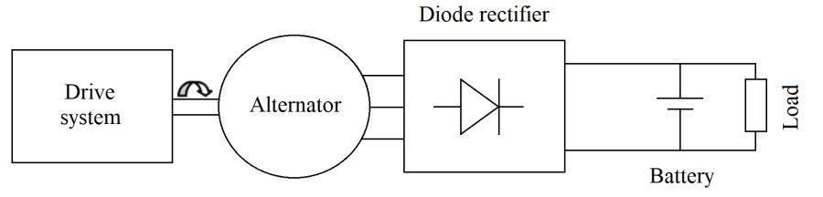
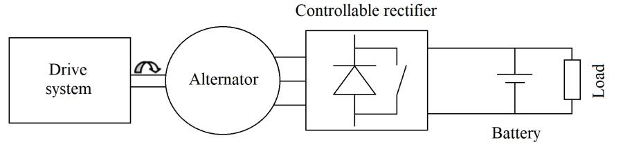
– an alternator connected to a diode rectifier (Figure 1.7(b));
– an alternator connected to a controllable rectifier (Figure 1.7(c)).
a) Alternator connected to the electrical grid (constant speed)
b) Alternator connected to a diode rectifier.
b) Alternator connected to a controllable rectifier.
Figure 1.7. Example applications of alternators
The first case corresponds to constant-speed operations, in which the electrical grid imposes the frequency. Of all the studies conducted on hybrid excited machines that use this type of application, two predominant motivations can be identified:
– improving the performance of conventional wound field excitation alternators (Fukami et al. 2010; Yamazaki et al. 2012);
– investigating the performance of hybrid excited alternators used in this type of application (Ammar et al. 2012; Kamiev et al. 2012, 2013, 2014; Kamiev 2013).
Although not fundamentally contradictory, these two motivations reflect different ambitions and therefore give rise to different approaches. These two motives can also be found in the other application cases.
For the first category, it is a question of starting from an existing wound field excitation alternator for which the addition of permanent magnets allows for the performance to be improved, increasing the amount of power delivered and also increasing the efficiency (Fukami et al. 2010; Yamazaki et al. 2012).
The second, and more general category, allows for a better understanding of the contribution that hybrid excitation brings when used in this type of application. They begin with qualitative (Ammar et al. 2012; Kamiev et al. 2012, 2014; Kamiev 2013) or quantitative (Kamiev et al. 2013), specifications, and then explore the performance of hybrid excited machines.
The second application case typically corresponds to alternators used in internal combustion motor vehicle applications (Bürger 1999), but not exhaustively. This type of association can also be found in the generation of onboard aircraft electrical power (Nasr 2017). As before, we can find studies where hybrid excitation is sought to improve the performance of existing wound excitation alternators (Albert 2004), and studies are now starting to integrate hybrid excitation, beginning with the design phase (Takorabet 2008; Nasr 2017).
Prior to the development of purely electric vehicles, the automotive industry experienced a period during which the onboard electrical power of internal combustion vehicles increased considerably, to accommodate the presence of more and more electrical equipment (Albert 2004). This trend is also present in the aviation industry (Roboam et al. 2012).
Hybrid excited alternators have been studied to address this issue (Albert 2004; Takorabet 2008). The interest in hybrid excitation for the “variablespeed alternator/diode rectifier” associations (Figure 1.7(b)) is trivial. Indeed, in this case, hybrid excitation allows for the DC bus voltage to be controlled, without requiring the use of a controllable rectifier (Amara et al. 2010) (Figure 1.7(c)), while the use of permanent magnets ensures high efficiency over a broad operational range.
The third application case corresponds to the reciprocal operation of the motoring mode operation, discussed previously in section 1.2.1. As for the motoring mode operation, the optimal control strategy depends on the value of the normalized inductance in the direct axis.
Overall, whether for motoring or generating operations, the use of hybrid excitation allows for greater flexibility in the design and the operation of synchronous machines. The permanent magnets allow them to operate with very high efficiency. Wound field excitation makes it possible to control the air-gap magnetic flux, thus making it possible to adapt these machines to very demanding specifications. However, this comes at the cost of a greater complexity when compared to single excitation synchronous machines, whether they use wound field excitation or permanent magnets.
1.3. Hybrid excited structures
The principle of hybrid excitation allows for a wide variety of structures to be realized, and so many criteria can then be used when classifying hybrid excited synchronous machines. The classical criteria used in the classification of other types of electrical machines are often used. For example, we have:
1) radial or axial flux machines (for rotational machines);
2) machines with a 2D (magnetic flux circulating mainly in one plane) or a 3D (magnetic flux circulating in three dimensions) structure;
3) rotary and linear machines.
Several publications have been devoted to classifying synchronous hybrid excited structures (Amara et al. 2001, 2004a, 2007; Hlioui et al. 2013; Kamiev 2013; Yang et al. 2016; Asfirane et al. 2019; Zhu and Cai 2019). Therefore, we will not go into detail on the great variety of hybrid excited structures, but instead propose an updated synthesis, highlighting the strong
trends, while citing a large number of references. The reader can refer to them to consolidate their understanding and clarify the elements presented in this section.
1.3.1. Classification criteria
There are many criteria used in the classification but, given the principle that hybrid excitation uses two sources of magnetic excitation flux (Figure 1.1), i.e. permanent magnets and excitation coils, two criteria seem to be better suited:
1) By analogy with electric circuits, the way in which the two excitation flux sources are combined: series hybrid excited synchronous machines (SHESMs), and parallel hybrid excited synchronous machines (PHESMs) (Amara 2001).
2) The localization of excitation flux sources within the machine: both sources in the stator, both sources in the rotor, or a mixed localization. By mixed localization, we mean that one field source (wound field excitation coils or permanent magnets) is located within the rotor, or within the stator, and the other field source is in the stator or the rotor, respectively. Having wound field excitation coils in the stator is preferred to avoid sliding contacts (Amara et al. 2011; Kamiev 2013).
The first criterion makes it possible to situate hybrid excited machines in the general, broader, framework of magnetic circuits (Amara 2001), with an important influence on the efficiency of excitation flux control. It is a criterion that can be qualified as fundamental when compared with the second one, which is more in line with technological and industrial considerations.
Indeed, the location of the sources can have a strong impact on the manufacturing complexity of the machines. Having all the excitation sources, as well as the armature windings, in the stator, which allows for a completely passive moving part, simplifies the construction and offers functional advantages. Cooling, for example, is simplified. Flux-switching hybrid excited synchronous machines correspond to this description, and this is not unrelated to the interest shown in research laboratories (Yang et al. 2016; Asfirane et al. 2019; Zhu and Cai 2019) and (Hoang et al. 2007; Sulaiman et al. 2011; Wang and Deng 2012a, 2012b).
We now will present an updated synthesis of hybrid excited structures by classifying them according to the first criterion, although the others will not be neglected.
1.3.1.1. Series hybrid excited synchronous machines (SHESMs)
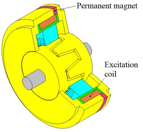
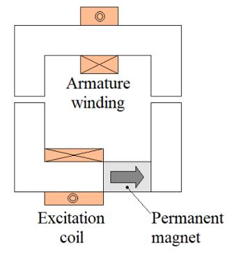
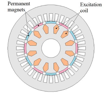
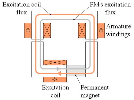
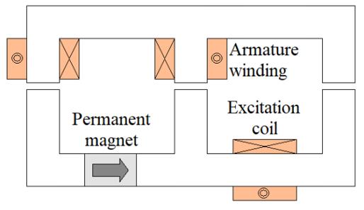
Figure 1.8 illustrates the principle of series hybrid excitation. Figure 1.8(c) shows a series hybrid excited synchronous machine (Mizuno 1997; Fodorean et al. 2007).
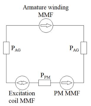
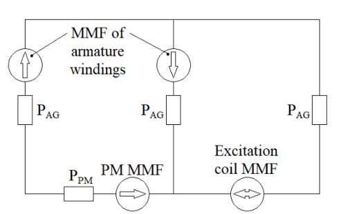
Figure 1.8(a) shows a schematic diagram of series hybrid excitation, and Figure 1.8(b) shows the equivalent magnetic circuit. The two excitation sources are in series. The relative permeability of the ferromagnetic parts is assumed to be infinite. PAG and PPM represent the permeances of the air-gap (AG) and the permanent magnet (PM), respectively.
a) Schematic diagram. b) Equivalent magnetic circuit.
c) Example of a series hybrid excited synchronous machine (Mizuno 1997; Fodorean et al. 2007).
Figure 1.8. Series hybrid excitation
Figure 1.9 illustrates how the strengthening, or weakening, of the excitation field of the magnet is achieved by supplying the excitation coil with a current in either direction.
a) Strengthening the excitation flux of the magnet.
b) Weakening the excitation flux of the magnet
Figure 1.9. Control of the total excitation flux for SHESMs
In SHESMs, since the excitation flux created by the excitation coils must pass through the PMs (Figure 1.9) which have low relative permeability (μrPM ≈ 1), i.e. a low permeance PPM (Figure 1.8(b)), the flux control capability is expected to be less effective than that found in parallel hybrid excited structures. In addition, the risk of demagnetizing the PMs raises concerns. However, since the excitation fluxes created by either source follow the same path, the iron losses decrease when the excitation flux of the PMs is weakened, which is not the case for all hybrid excited machines.
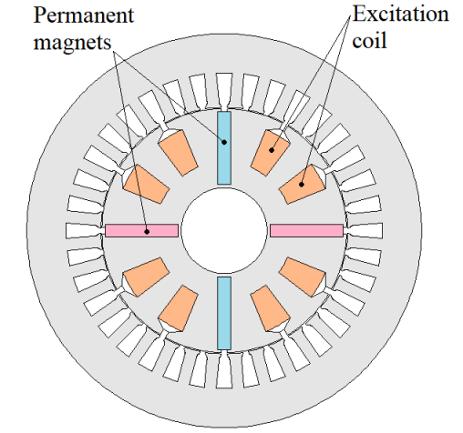
The structure shown in Figure 1.8(c) is a 2D structure, in which both excitation sources are found in the rotor. The structure shown in Figure 1.2 is also a SHESM, although in 3D and with the two sources located in the stator. Other SHESM structures will be illustrated in section 1.3.2.
1.3.1.2. Parallel hybrid excited synchronous machines (PHESMs)
Figure 1.10 illustrates the principle of parallel hybrid excitation. Figure 1.10(c) shows a parallel hybrid excited synchronous machine (Akemakou and Phounsombat 2000).
a) Schematic diagram.
b) Equivalent magnetic circuit.
c) Example of a parallel hybrid excited synchronous machine (Akemakou and Phounsombat 2000).
Figure 1.10. Parallel hybrid excitation