
Nanotechnology-Based Additive Manufacturing: Product Design, Properties, and Applications Volumes 1-2 1st Edition Kalim Deshmukh
Visit to download the full and correct content document: https://ebookmass.com/product/nanotechnology-based-additive-manufacturing-produ ct-design-properties-and-applications-volumes-1-2-1st-edition-kalim-deshmukh/

More products digital (pdf, epub, mobi) instant download maybe you interests ...

Additive and Traditionally Manufactured Components: A Comparative Analysis of Mechanical Properties (Additive Manufacturing Materials and Technologies) 1st Edition Joshua Pelleg Phd
https://ebookmass.com/product/additive-and-traditionallymanufactured-components-a-comparative-analysis-of-mechanicalproperties-additive-manufacturing-materials-and-technologies-1stedition-joshua-pelleg-phd/

Smart Materials in Additive Manufacturing, Volume 2: 4D Printing Mechanics, Modeling, and Advanced Engineering Applications Mahdi Bodaghi
https://ebookmass.com/product/smart-materials-in-additivemanufacturing-volume-2-4d-printing-mechanics-modeling-andadvanced-engineering-applications-mahdi-bodaghi/

Metal Additive Manufacturing Ehsan Toyserkani
https://ebookmass.com/product/metal-additive-manufacturing-ehsantoyserkani/

Fast Desktop-Scale Extrusion Additive Manufacturing (Article, NOT a book) Jamison Go
https://ebookmass.com/product/fast-desktop-scale-extrusionadditive-manufacturing-article-not-a-book-jamison-go/

Additive Manufacturing 1st Edition Juan Pou Antonio
Riveiro Paulo Davim
https://ebookmass.com/product/additive-manufacturing-1st-editionjuan-pou-antonio-riveiro-paulo-davim/
Product Maturity 1 : Theoretical Principles and Industrial Applications 1st Edition Franck Bayle
https://ebookmass.com/product/product-maturity-1-theoreticalprinciples-and-industrial-applications-1st-edition-franck-bayle/

Smart Materials in Additive Manufacturing, Volume 1: 4D
Printing Principles and Fabrication Mahdi Bodaghi
https://ebookmass.com/product/smart-materials-in-additivemanufacturing-volume-1-4d-printing-principles-and-fabricationmahdi-bodaghi/

Organogermanium Compounds: Theory: Experiment, and Applications, 2 Volumes Lee V.Y. (Ed.)
https://ebookmass.com/product/organogermanium-compounds-theoryexperiment-and-applications-2-volumes-lee-v-y-ed/

Smart Materials in Additive Manufacturing Volume 1: 4D
Printing Principles and Fabrication Mahdi Bodaghi & Ali Zolfagharian
https://ebookmass.com/product/smart-materials-in-additivemanufacturing-volume-1-4d-printing-principles-and-fabricationmahdi-bodaghi-ali-zolfagharian/

Nanotechnology-Based Additive Manufacturing
Product Design, Properties, and Applications
Edited by Kalim Deshmukh, S.K. Khadheer Pasha, Kishor Kumar Sadasivuni
Volume 1
Nanotechnology-Based Additive Manufacturing
Product Design, Properties, and Applications
Edited by Kalim Deshmukh, S.K. Khadheer Pasha, Kishor Kumar Sadasivuni
Volume 2
Editors
Kalim Deshmukh
University of West Bohemia New Technologies Research Center Univerzitni 8, 30614 Plzeň Czech Republic
S.K. Khadheer Pasha VIT‐AP University Department of Physics Near Vijayawada 522237 Andhra Pradesh India
Kishor Kumar Sadasivuni Qatar University Center for Advanced Materials Al‐Tarfa, University Street Doha Qatar
Cover Image: © BLACKDAY/Shutterstock
All books published by WILEY-VCH are carefully produced. Nevertheless, authors, editors, and publisher do not warrant the information contained in these books, including this book, to be free of errors. Readers are advised to keep in mind that statements, data, illustrations, procedural details or other items may inadvertently be inaccurate.
Library of Congress Card No.: applied for British Library Cataloguing-in-Publication Data
A catalogue record for this book is available from the British Library.
Bibliographic information published by the Deutsche Nationalbibliothek
The Deutsche Nationalbibliothek lists this publication in the Deutsche Nationalbibliografie; detailed bibliographic data are available on the Internet at <http:// dnb.d-nb.de>.
© 2023 Wiley‐VCH GmbH, Boschstr. 12, 69469 Weinheim, Germany
All rights reserved (including those of translation into other languages). No part of this book may be reproduced in any form – by photoprinting, microfilm, or any other means –nor transmitted or translated into a machine language without written permission from the publishers. Registered names, trademarks, etc. used in this book, even when not specifically marked as such, are not to be considered unprotected by law.
Print ISBN: 978-3-527-35230-2
ePDF ISBN: 978‐3‐527‐83545‐4
ePub ISBN: 978‐3‐527‐83546‐1
oBook ISBN: 978‐3‐527‐83547‐8
Typesetting Straive, Chennai, India
Contents
Volume 1
Preface xiii
1 State-of-the-Art Overview and Recent Trends in Additive Manufacturing: Oppor tunities, Limitations, and Current Market 1
Rajkumar Velu, Murali K. Ramachandran and S. Anand Kumar
1.1 Introduction 1
1.2 Classification of AM Processes 6
1.2.1 Powder Bed Fusion 6
1.2.2 Binder Jetting 7
1.2.3 Material Extrusion 8
1.2.4 Material Jetting 10
1.2.5 Sheet Lamination 11
1.2.6 Direct Energy Deposition 13
1.2.7 VAT Polymerization 14
1.3 Recent Trends in AM 16
1.3.1 AM Software Solutions in Simulation 16
1.3.2 AM and Machine Connectivity 17
1.3.3 Converge of AM and AI 17
1.3.4 Automation and Workflow 18
1.3.5 Advancement in AM Amenable Materials Development 19
1.3.6 Economics of Manufacturing 19
1.3.7 Limitations 20
1.3.8 Sustainability in AM 20
1.4 Conclusion and Outlook 21
References 22
2 Additive Manufacturing Technologies and Post-processing, Design Optimization, and Material Considerations for Reliable Printing 27
Pankaj K. Singh, Santosh Kumar, and Pramod K. Jain
2.1 Introduction 27
2.2 Chronological Evolution of AM Technologies 28
2.2.1 Vat Polymerization or Stereolithography (SLA) 29
2.2.2 Material Jetting (MJ) 29
2.2.3 Fused Deposition Modeling (FDM) 31
2.2.4 Laminated Object Manufacturing (LOM) 31
2.2.5 Binder Jetting (BJ) 32
2.2.6 Powder Bed Systems 33
2.2.7 Powder Feed Systems or Direct Energy Depositions (DED) 34
2.2.8 Wire Feed System or Wire Arc AM (WAAM) 35
2.3 Post-processing Techniques 36
2.4 Design Optimization 38
2.5 Materials 41
2.6 Conclusions 42 Acknowledgments 44 References 44
3 Nanomaterials and Nanostructures in Additive Manufacturing: Properties, Applications, and Technological Challenges 53 Sathish K. Kurapati, N. Mahendar Reddy, R. Sujithra, Ramesh Kola, Gubbala V. Ramesh and D. Saritha
3.1 Introduction 53
3.2 Classification of Nanomaterials 54
3.2.1 Functionalized Nanomaterials and Nanostructures in Additive Manufacturing 57
3.3 Properties of Nanomaterials/Composites in Additive Manufacturing 57
3.3.1 Mechanical Properties 58
3.3.2 Thermal Properties 60
3.3.3 Responsive Properties 61
3.3.4 Optical Properties 62
3.3.5 Geometric Properties 63
3.3.6 Biological Properties 64
3.4 Applications 65
3.4.1 Energy Conversion and Storage Applications 66
3.4.1.1 Thermoelectric 66
3.4.1.2 Supercapacitors 68
3.4.1.3 Batteries 73
3.4.1.4 Solar Cells 76
3.4.2 Sensing Applications 78
3.4.3 Thermal Management Applications 79
3.4.4 Biomedical Applications 80
3.5 Technological Challenges 81
3.5.1 Risk of Nanomaterial in 3D Printing: Human Health and Safety-Related 81
3.5.2 Regulatory Issues 87
3.5.3 Design Limitations 88
3.6 Conclusions 88 References 88
4 Metal Additive Manufacturing of PEM Fuel Cell Flow Field Plates and the Scope of Nanomaterials for Its Fabrication 103 Arunkumar Jayakumar, Dinesh K. Madheswaran and Rajkumar Velu
4.1 Introduction 103
4.2 Materials Used for Flow Field Plates 105
4.2.1 Graphite Plates 106
4.2.2 Polymer Composites 106
4.2.3 Metal Plates 107
4.3 Additive Manufacturing of Metal Flow Field Plates 109
4.4 Can Nanomaterials + Additive Manufacturing Be a Game-Changer? 115
4.5 Outlook and Prospectus 116
References 117
5 Additive Manufacturing of Ceramic-Based Materials 131 Priyanka Rani, Kalim Deshmukh, J. Gounder Thangamani and Shaik Khadheer Pasha
5.1 Introduction 131
5.2 Ceramic Materials 133
5.3 Ceramic Additive Manufacturing 134
5.4 CAM: Single-Step Processing 136
5.4.1 Direct Energy Deposition (DED) 136
5.4.2 Selective Laser Sintering 138
5.5 CAM: Multi-Step Processing 139
5.5.1 Powder Bed Fusion (PBF) 139
5.5.2 Binder Jetting 141
5.5.3 Laminated Object Manufacturing 143
5.5.4 Material Extrusion 144
5.5.4.1 Fused Filament Fabrication 144
5.5.5 Material Jetting 145
5.5.5.1 Direct Ink Printing 145
5.5.6 Photopolymerization 147
5.5.6.1 Ceramic Stereolithography (CSL) 147
5.5.6.2 Digital Light Processing (DLP) 149
5.6 Different Ceramic-Based Materials Fabricated by Additive Manufacturing (AM) 150
5.7 Conclusion and Future Prospects 151 References 152
6 Additive Manufacturing of Tunable Metamaterials 161 Kadir Günaydın, Zana Eren and Zafer Kazancı
6.1 Introduction 161
6.2 Mechanical Metamaterials 162
6.2.1 Introduction 162
6.2.2 VAT Polymerization 163
6.2.3 Selective Laser Melting 164
6.2.4 Electron Beam Melting 165
6.2.5 Material Jetting 166
6.2.6 Selective Laser Sintering 167
6.2.7 Fused Deposition Modeling 168
6.3 Electromagnetic Metamaterials 169
6.3.1 Material Extrusion 169
6.3.2 Inkjet Printing 171
6.3.3 VAT Polymerization 173
6.4 Acoustic Metamaterials 173
6.4.1 Introduction 173
6.4.2 Fused Deposition Modeling 174
6.4.3 Material Jetting 175
6.4.4 Powder-Bed Fusion 176
6.4.5 VAT Polymerization 176
6.5 Multimaterial Approaches 177
6.5.1 Material Extrusion 177
6.5.2 Inkjet Printing 179
6.5.3 VAT Polymerization 180
6.6 Conclusions 181 References 181
7 Additive Manufacturing of Hydrogels 189
Guntoju Srikanth, Saraswathi Kailasa, Dunna Manikanta, Kishor K. Sadasivuni and Kalagadda Venkateshwara Rao Abbreviations 189
7.1 Introduction 190
7.2 History of AM 191
7.3 Role of Nanomaterials and Nanostructures in AM 192
7.4 Importance of Hydrogels 192
7.5 AM Techniques 193
7.5.1 Liquid-Based Techniques 194
7.5.1.1 Stereolithography 194
7.5.1.2 Inkjet Printing 194
7.6 Powder-Based Techniques 195
7.6.1 Selective Laser Sintering 195
7.7 Molten Filament-Based Techniques 195
7.7.1 FDM Extrusion and Deposition Process 195
7.7.2 Synthesis of Hybrid Nanomaterials 196
7.7.3 Metal Nanomaterial-Based Hydrogels in AM 196
7.7.4 Metal Oxide Nanomaterial-Based Hydrogels in AM 197
7.7.5 Carbonaceous Nanomaterial-Hydrogel Based in AM 197
7.7.6 Polymer Nanomaterial-Based Hydrogel in AM 199
7.8 AM-Printed Hydrogel Application-Based Hybrid Nanomaterials 199
7.9 Biomedical Applications Based on Printed Hydrogels 202
7.10 3D-Printed Hydrogel-Based Biosensors 205
7.11 Lab on a Chip-Based 3D-Printed hydrogels 206
7.12 3D-Printed Hydrogel-Based Wearable and Other Applications 206
7.13 Actuators Based on 3D-Printed Hydrogels 209
7.14 Future Scope of AM through 3D printing of Hydrogels 210
7.15 Conclusions 212
Acknowledgment 212
References 212
8 Self-Healing Polymers and Composites for Additive Manufacturing: Materials, Properties, and Applications 219 Young N. Kim, Hyunsung Jeong, Sooyeon Ryu, and Yong C. Jung
8.1 Introduction 219
8.2 Extrinsic and Intrinsic Self-Healing Systems 220
8.2.1 Extrinsic Self-Healing System 221
8.2.2 Intrinsic Self-Healing System 228
8.2.3 3D/4D Self-Healing Polymer and Composite 234
8.3 Conclusions 242
Acknowledgments 242
References 243
9 Stimuli-Responsive Smart Materials for Additive Manufacturing 249 Ana C. Pinho and Ana P. Piedade
9.1 Introduction 249
9.2 External Stimuli 250
9.2.1 Temperature 250
9.2.2 Moisture 250
9.2.3 pH 251
9.2.4 Light 251
9.2.5 Magnetic 251
9.2.6 Mechanical Loading 252
9.2.7 Solvent 252
9.3 Stimuli-Responsive Smart Materials 253
9.3.1 Polymers 253
9.3.1.1 Shape Memory Polymers 253
9.3.1.2 Photocurable Polymers 255
9.3.1.3 Hydrogels 256
9.3.1.4 Liquid Crystal Polymers 259
9.3.1.5 Bioinks 260
9.3.1.6 Composites 261
9.3.2 Metallic Materials 262
9.3.2.1 NiTi Alloys 263
9.3.2.2 Cu-Based Alloys 265
9.3.2.3 Ni–Mn–Ga Alloys 266
9.3.3 Ceramics 267
9.4 Conclusions and Future Perspectives 268 Acknowledgments 269 References 269
10 Additive Manufacturing of Multifunctional Polymer Nanocomposites: From 3D to 4D 277
Km Nikita, Dikin Patel and Gautam Patel
10.1 Introduction 277
10.2 Types and Classification of Nanomaterials 278
10.2.1 Carbon-Based Nanomaterials 278
10.2.2 Inorganic NMs 278
10.2.3 Organic NMs 279
10.2.4 Composite NMs 279
10.3 Classification of Nanomaterials Based on Their Dimensions 279
10.4 Classification of Nanomaterials Based on Their Origin 280
10.5 Multifunctional Polymer Nanocomposites 280
10.6 Additive Manufacturing (AM) Process 281
10.7 Classification of Additive Manufacturing Technology 283
10.7.1 Material Jetting Process (MJ) 283
10.7.2 Polyjet Printing 284
10.7.3 Binder Jetting (BJ) 284
10.7.4 Vat Photo Polymerization 285
10.7.5 Stereolithography (SLA) 285
10.7.6 Direct Light Processing (DLP) 286
10.7.7 Powder Bed Fusion (PBF) 286
10.7.8 Material Extrusion (ME) 287
10.7.9 Directed Energy Deposition (DED) 288
10.7.10 Sheet Lamination 288
10.8 Additive Manufacturing of Multifunctional Polymer Nanocomposites 289
10.9 4D Printing 291
10.10 Recent Advances in 3D/4D Printing of Polymer Nanocomposites 293
10.11 Conclusion 300
References 301
11 Additive Manufacturing of Fiberglass-Reinforced Polymer Composites 315
Jianxiong Zhu, Haiying Wen, Hui Zhang and Zhisheng Zhang
11.1 Introduction 315
11.2 Fabrication Method 317
11.3 Physical/Chemical Characteristics 318
11.4 Application in Piezoelectric/Triboelectric Energy Harvesting 319
11.5 Application in Magnetic/Triboelectric Energy Harvesting 323
11.6 Applications in Sensing 327
11.7 Challenges and Future Perspectives 330
11.8 Conclusions 331
Acknowledgments 331
References 331
12 Advanced 2D Nanomaterials for Additive Manufacturing 335
Suhail Mubarak, Nidhin Divakaran, Ashish Raghavan, Sathish Kumar
Ramachandran and Jianlei Wang
12.1 Introduction 335
12.2 Hexagonal Boron Nitride (hBN) 336
12.2.1 Introduction 336
12.2.2 2D-hBN Nanosheets: Fabrication and Advancement 338
12.2.2.1 Exfoliation Using Mechanical Method 338
12.2.2.2 Exfoliation Using Liquid 339
12.2.2.3 CVD (Chemical Vapor Deposition) 339
12.2.2.4 Exfoliation Using Ion-Intercalation 339
12.2.2.5 PVD 340
12.2.3 2D-hBN: Properties and Application 340
12.2.4 2D hBN in Additive Manufacturing 341
12.3 MXenes 344
12.3.1 Introduction 344
12.3.2 Synthesis of MXenes 345
12.3.3 MXenes for Additive Manufacturing 346
12.4 Transition Metal Dichalcogenides (TMDs) 351
12.4.1 Introduction 351
12.4.2 Synthesis of TMDs 351
12.4.3 TMDs for Additive Manufacturing 352
12.5 Graphene 354
12.5.1 Introduction 354
12.5.2 Synthesis of Graphene 356
12.5.3 Graphene for Additive Manufacturing 356
12.6 Conclusion 360
References 361
Volume 2
Preface xv
13 Nanomaterials-Based Additive Manufacturing for Mass Production of Energy Storage Systems: 3D Printed Batteries and Supercapacitors 369 R. Sujithra, B. Dhatreyi and D. Saritha
14 Additively Manufactured Electrochemical Sensors and Biosensors 399
Malayanur L. Aruna Kumari, Peram Lokanatha Reddy, Jayaraman Theerthagiri, Seung Jun Lee, Arun Prasad Murthy, Yiseul Yu and Myong Yong Choi
15 Additive Manufacturing Techniques for Designing Advanced Scaffolds for Bone Tissue Engineering 435 Yasir B. Pottathara and Vanja Kokol
16 Additive Manufacturing of Smart Bionanomaterials for Fabrication of Medical Implants 455
Babita Sumathy, Lakshmi V. Nair, Vineeth M. Vijayan, Anil Kumar, P. R., Shiny Velayudhan and Vinoy Thomas
17 Additive Manufacturing Techniques for Drug Delivery Applications 495
Subhasree Panda, Kalim Deshmukh, Tangirala Venkata Krishna Karthik, and Shaik Khadheer Pasha
18 Applications of Additive Manufacturing Techniques in the Fabrication of Thermoelectric Materials and Devices 527
Priyanka Rani, Kalim Deshmukh, Mohan Kumar Kesarla, Tathagata Kar, and Shaik Khadheer Pasha
19 Applications of Additive Manufacturing Techniques in Aerospace Industry 561
S. Anand Kumar, Akshay Pathania, Abhishek Shrivastava, V. Rajkumar, and Prasad Raghupatruni
20 Development of 3D Concrete Printing Using Additive Manufacturing Processes for Construction and Building Industry 579
S. Shanmugan, T. Sandhyarani and S. Palani
21 Machine Learning in Additive Manufacturing 601
Hameed Khan, Kamal K. Kushwah, Saurabh Singh, Jitendra S. Thakur, and Kishor K. Sadasivuni
22 Modeling Strategies and Computer-Aided Designs for Producing Optimized Performance of Additively Manufactured Nanomaterials 637
Daniel Moreno-Nieto, Pedro Burgos-Pintos, and Daniel Moreno-Sánchez
23 Success Stories of the Digital Manufacturing Laboratories in SARS-CoV-2 Pandemic 667
Mohamed Zied Chaari, Abdulaziz Aljaberi, Rashid AL-Rahimi, and Mohamed Abdelfath
24 Environmental Impact, Challenges for Industrial Applications and Future Perspectives of Additive Manufacturing 691
Rajkumar Velu, Roopa Tulasi, and Murali K. Ramachandran
Index 711
Preface
Additive manufacturing (AM) or three‐dimensional (3D) printing is a versatile and powerful technology that allows fabricating 3D structures of complex geometries using different software and computer‐aided designs (CAD). AM has opened up a whole new era of digital design and manufacturing with emerging revolutions in the world mainly due to the complexity of the computer‐designed objects as compared to the conventional machine parts. The evolution of 3D printing and AM technologies has changed design strategies, engineering, and manufacturing processes across various industries such as consumer products, aerospace, medical devices, construction, and automobiles. AM allows larger design flexibility, customized products, reduced waste, low cost, and efficient prototyping enabling their elevated performance that helps in the transition of the digital world. Compared to other manufacturing techniques, AM technologies enable the rapid fabrication of multifunctional materials and structures in the range from the nanoscale to microscale to macroscale. Thus, AM and 3D printing technologies are developing impressively and are expected to bring about the next industrial revolution.
Nanotechnology, which combines diverse disciplines such as physics, chemistry, biotechnology, and engineering, has been proven to be an essential technology to bring innovation in the material science field. The integration of nanotechnology and AM can create a wide variety of materials with intelligent designs and structures for new and innovative applications. The present book offers innovative, breakthrough research developments and trends in various nanomaterials‐based AM. This book provides a thorough and clear understanding of the basics of AM techniques with an emphasis on fundamental processes, optimization of processes, product designs, and product parameters that can be considered for reducing the manufacturing cost, materials, and various applications. In addition, the book also covers recent developments in different types of nanomaterials‐based AM for various applications. Moreover, the environmental effect of AM technologies has also been discussed as it has a serious impact on our society and daily life and has significant involvement in technological growth. The main benefit of this book is its highly practical approach, i.e. it will provide “hands‐on” information and insights on various AM technologies.
This book provides a comprehensive and state‐of‐the‐art review on various AM technologies, their advantages, shortcomings, potential applications, and future directions. The applications of AM technologies in electronics, aerospace, construction, automobile, sports, and biomedical fields have been discussed, and in each case, the information regarding material considerations, the requirement of specific design, fabrication, and processing methods have been discussed in detail. This book will be an excellent reference source for graduate and postgraduate students, academic researchers, scientists, R&D professionals, and engineers working across different disciplines and industries for designing and obtaining technologically novel and economically viable additively manufactured materials or products for advanced technologies. Overall, with all the knowledge and important information in this field, it is anticipated that the content of this book will further provide a better understanding of AM technologies, offering the current state of the art in additively manufactured materials, products, and their applications.
We are highly grateful to all the authors for their zealous hard work and excellent contributions to the publication of this book. We also thank Dr. Martin Preuss, Daniela Bez, and other staff members of the Wiley‐VCH family for their dedicated support and valuable assistance during the publication of this book. Finally, we offer our sincere appreciation to Wiley‐VCH for the publication of this book.
31 October 2022 Kalim Deshmukh
New Technologies Research Center, University of West Bohemia Univerzitní 8, 30614 Plzeň Czech Republic
S.K. Khadheer Pasha
Department of Physics, VIT ‐ AP University Amaravati, Guntur Andhra Pradesh 522501 India
Kishor Kumar Sadasivuni Center for Advanced Materials, Qatar University PO Box 2713, Doha Qatar
1
State-of-the-Art Overview and Recent Trends in Additive Manufacturing: Opportunities, Limitations, and Current Market
Rajkumar Velu1, Murali K. Ramachandran2 and S. Anand Kumar1
1 Indian Institute of Technology Jammu (IIT - Jammu), Department of Mechanical Engineering, NH-44, PO Nagrota, Jagti, Jammu and Kashmir, 181 221, India
2 Singapore University of Technology and Design (SUTD), Engineering Product and Development, Digital Manufacturing and Design Laboratory, 8 Somapah Rd, Singapore, 487372, Singapore
1.1 Introduction
Additive manufacturing (AM) in general is known as rapid prototyping (RP) and popularly called 3D printing. Figure 1.1 represents the history of the machine technology of AM originated in the twentieth century (the 1960s and 1970s). However, the AM process was commercially successful during the 1980s. Charles Hull was the first patent recipient and made the system saleable to create a part or model in a layer by layer as 3D objects [1, 2]. It is also known for multiple names such as additive fabrication, direct digital manufacturing, rapid manufacturing, layer manufacturing, solid freeform process, and additive process. This technology assists engineers not only to visualize the model but also to fabricate innovative 3D-printed parts [3, 4]. AM can assist software developers and management consultants in illustrating the business model and other related software solutions. Additionally, in a variety of subfunctions that allow their clients and other stakeholders to provide input during the development process. Outwardly, the AM process includes various designs, form fit and checking, tools, patterns, conceptual parts, and models, as required with all the functional properties for industrial applications [5].
From the 1980s, AM was propelling toward rapid growth in a wide range of processing of advanced material systems using various energy sources and chemical reactions. Though the AM process involves rendering from the material, its classification originates from the physical structures of various materials, such as powder-based, liquid-based, and solid-based processes. In 2010, the American Society for Testing and Materials (ASTM F42) framed standards to categorize AM processes (classification are described in Table 1.1) as follows: (i) VAT polymerization,
Nanotechnology-Based Additive Manufacturing: Product Design, Properties, and Applications, First Edition. Edited by Kalim Deshmukh, S.K. Khadheer Pasha, and Kishor Kumar Sadasivuni. © 2023 WILEY-VCH GmbH. Published 2023 by WILEY-VCH GmbH.
Charles Hull –Invented stereolithography (SLA) 1983
MAKERBOT and FARSOON was founded
FDM pattern (STRATASYS) is expired
Scott Crump –Invented fused deposition modeling (FDM)
EOS founded HELISYS –Developed Sheet lamination
DTM – Invented selective laser sintering (SLS)
NORSK was founded ENVISIONTEC was founded
AI Siblani –patented DLP Binder jetting patent granted
STRATASYS –patented Material jetting
EOS – Developed Direct metal laser sintering (DMLS)

ULTIMAKER was founded CARBON MARKFORGED was founded
MARKFORGED introduced first continuous carbon fibre 3D printer (mark one)
DESKTOP METAL acquires ENVISIONTEC
Figure 1.1 Evolution of machine technology in the twentieth and twenty-first centuries.
Powder-based technologies
Material deposition technologies Laminated object manufacturing
Selective laser melting (SLM)
Electron beam melting (EBM)
Electrographic layered manufacturing
Once stage selective laser sintering
Selective masking sintering
Selective inhibitor sintering
High speed sintering
Laser engineered net shaping
Laser cladding
Laser metal deposition shaping
Directed light fabrication
Direct metal deposition
3D printing
Two-stage selective lasersintering
Liquid-based manufacturing
Stereolithography Thermoset resin
1 State-of-the-Art
Table 1.1 Predominant classification of AM techniques.
S. No.
Classification of AM process
1 VAT polymerization
2 Material jetting
Energy or binders incorporated Applications
Plastics and polymers
Polymers: Photopolymer resin
Photopolymers (liquid form) and cast wax
3 Binder jetting
1) Full colored sandstone
2) Silica sand
3) Stainless steel
4) Inconel
5) Tungsten carbide
4 Material extrusion
5 Powder bed fusion
6 Sheet lamination
7 Direct energy deposition
High and low temperature polymer; advance materials (nylon, flexible filaments and carbon fiber filament)
Selective heat sintering – Nylon
DMLS, SLM, SLS – stainless steel, titanium, aluminum, cobalt chrome, steel
EBM – titanium, cobalt chrome, stainless steel, aluminum and copper
Material has capability to roll – paper, plastic, and some sheet metals
Uses only metals; neither polymers or ceramics.
Metals – cobalt chrome, titanium
Finer and smooth surface finish – jewelry, investment casting, dental and other medical applications
Multi-material parts with accuracy and minimal material waste (medical and casting patterns)
Fabrication of full color prototypes (like figurines), large sand-casting cores and molds and some low-cost metal parts
Manufacturing industries (jigs, fixtures), medical (surgical tool, dental fixtures), pharmaceutical (customizable tablets) etc.
Industry and medical sector (orthopedic parts such as Ti alloy cranial), aerospace (fuel nozzle), automotive industries (turbo charger, air duct etc.)
Ceramics and composite fibers parts, full colored parts
Aerospace brackets, tanks and ribs (near net shape parts); feature addition (print on existing parts) and to repair damaged parts (turbine blades or propellers)
(ii) material jetting (MJ), (iii) binder jetting, (iv) material extrusion (MEX), (v) powder bed fusion (PBF), (vi) sheet lamination (SHL), and (vii) direct energy deposition (DED). The materials used in these processes include the following:
● Polymers such as ABS (acrylonitrile butadiene styrene), PLA (polylactide) including soft PLA, PC (polycarbonate), polyamide (nylon), Nylon 12 (tensile strength 45 Mpa), glass-filled nylon (12.48 Mpa), epoxy resin, wax, photopolymer resins;
● Ceramics like silica/glass, porcelain, and silicon-carbide;
● Metals like Maraging steel 1.2709 (tensile strength 1100 Mpa), titanium alloy Ti6AI4V (tensile strength 1150 Mpa), 15-5 PH stainless steel (tensile strength 1150 Mpa), cobalt chrome alloy, Co28Cr6Mo (tensile strength 1300 Mpa), aluminum AlSi10mg (tensile strength 445 Mpa), gold, and silver [6].
Among the material rendering classification, the noteworthy and most successful technologies are PBF processes like selective laser sintering (SLS), direct metal laser sintering (DMLS), direct metal laser melting (DMLM)/electron beam melting (EBM), and selective laser melting (SLM) [7] to fabricate nonporous objects, high temperature-resistant parts, and high-resolution objects. AM is the disruptive technology that empowers the industry to fabricate low volume without compromising mechanical property [8]. Also, the process enhances the required property in the fabricated part by adjusting the material properties, and the entire process agglomerates in the digital form. Recently, engineering, communications, imaging, and architecture are undergoing to digital revolutions [9]. Despite this, AM remains the cause of digital flexibility and efficiency to manufacturing operations.
The basic working principle of AM technology involves creating a 3D model using CAD software like Solid Works, Creo, Auto CAD and Catia. From the 3D model, the materials are executed layer by layer in accurate geometrical shapes. The traditional manufacturing process involves removing material over milling, machining, carving, shaping, etc. But in contrast, as its name infers, AM adds material to build a part, which leads to product development in low time, cost, and human interaction. Also, the possibilities of achieving the complex shape and structure can be achieved, which is quite challenging to fabricate traditionally. RP helps engineers, scientists, and students to print parts for their wide range of applications rapidly [10].
Figure 1.3 represents various steps involved in the product development stages using RP. It elucidates that product fabrication is relatively rapid, and subsequent customized modifications and testing are highly possible.
Contextually, the AM process also collaborates with conventional or unconventional manufacturing techniques, called hybrid manufacturing. However, the challenging task is to check the material for AM process compatibility because the materials have physical, chemical, and molecular properties. Fabrication of any
Figure 1.3 Various steps involved in the product development stage.
functional components using the AM process requires pre-processing of materials either for solid or liquid or powder-based technologies. Even though such challenging and tremendous parameters are involved, the AM process proved its stand during the COVID 19 pandemic. Wohler’s report 2021 stated that AM industrial growth increased to 7.5% during the pandemic situation [11].
In this chapter, the working concept of AM technology is illustrated and correlates to the current high potential applications. Further, a comprehensive review converges on AM materials and the recent trend in their development. Eventually, it addresses the research, industrial opportunities, challenges, and limitations with the current market value.
1.2
Classification of AM Processes
1.2.1 Powder Bed Fusion
The PBF process suits both metals and polymers and remains one of the predominant techniques of AM processes. In terms of industrialized AM processes, it is the first one that was created at the University of Texas in Austin, USA. Figure 1.4 shows the schematic diagram of the essential operation and characteristics of the PBF process [12, 13]. While PBF procedures are identical across all techniques, minute variations required to boost machine productivity that allow for processing a broad variety of material compositions and prohibit the use of certain unique features. The fusion of powder particles requires one or more thermal sources to induce the particles in specified regions. The powders are fused using a thermal, laser, electron beam, and agent or energy, predominantly Laser and electron beams are used for fabricating highly complex structures.

Figure 1.4 Schematic of the powder bed fusion (PBF) process using nylon powder and sintered by the laser power source.
1.2 lassificationofAMProcesses 7
Theoretically, the materials that melt and resolidify are capable of use in PBF processes. The most common combination of materials used for PBF processes is polymer–composite, metal–composites, and ceramics–composites. The polymer composites, in most cases, are divided into two types: thermoplastic and thermosets. Thermoplastic materials are well suited for the PBF process; they possess low thermal conductivity and melting temperature, whereas thermoset polymers exposed to high temperatures will mainly degrade but not melt. The most common material used is nylon because of consistent melting points, which makes them more reliable [14, 15]. The polymer-composite parts from PBF are most applicable in biomedical research. Many scientists have scrutinized few polymers for their biocompatible and biodegradable characteristics [16]. Composites reinforced with hydroxyapatite and calcium silicate are used for fabricating bone replacement scaffolds. For use in medical applications, laser sintering has been used to create hydroxyapatite composite that mimics the actual human bone [17, 18]. For metal composites, materials capable of excellent weldabilities, such as typical stainless steel and tool steel and alloys like titanium-based, nickel-based, aluminum-based, and cobalt-chromium, are considered as candidate materials for PBF processes. However, the alloy that cracks under high solidification is unsuitable for metal laser sintering (MLS) [19]. The ceramic composite that commonly used in PBF methods are combination of materials such as oxides, carbides, and nitrides.
In PBF, it is easier to regulate the semi-crystalline process parameters, but handling the amorphous material is effective. Supports are also required for the metal PBF process. However, they are time-consuming and expensive for postprocessing. The limitation can be overcome by using a loose material as a support during polymer PBF, which saves time to build and post-process the parts. The liquid-based process has high accuracy and surface finish of the build parts related to PBF. This is due to more acceptable particle size that leads to a smoother surface finish and produces highly accurate details. Additionally, spreading and handling the powder are considered to be the most challenging task. At present, numerous newly designed machines are commercialized and possess unique characteristics like a detachable part bed to provide offline cooling and elimination of support, which means the part can be fabricated in a single build.
1.2.2 Binder Jetting
Binder jetting (BJ) was invented at MIT in the early 1990s and is commonly known as three-dimensional printing; this process is the modified version of inkjet technology. A powder-based material and a binder are the preferred two materials for this process. The binder turns as a bonding agent between the powder layers. The build material is usually in a powder form, and the binder is liquid, as shown in Figure 1.5. Alternating layers of the build material and the binding material are deposited through the horizontal movement of the print head along the x and y axes of the machine [20]. After completing the first layer, the printed object travels downwards on its build platform, which is appropriate to the PBF process. The BJ has an array of nozzle mounted on the machine setup for rapid patterning. Having such a
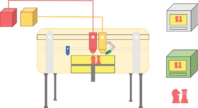
Figure 1.5 Schematic of the binder jetting (BJ) process using PMMA powder.
machine setup advances this technology to be economical and enables the part to print with a high speed at relatively low cost. The printed part remains in the part build bed until the binder cures and attains the required strength.
Postprocessing of the completed part involves removing unbonded powder particles with the help of pressurized air followed by infiltrating to increase the mechanical properties. The first commercialized material was invented from starch-based and water-based binders to print the part developed by Z corporation during the mid-1990s. Currently, calcium sulfate hemihydrate [21] is in use. However, the part printed from this material is relatively weak; therefore, the researchers experimented with infiltrating with other materials. The company named 3D Systems provided three different infiltrates, namely colorbond infiltrate, acrylate-based, and strengthmax infiltrate. Similar to superglue, one is salt-free, and the other is hazardfree infiltrate.
On the other hand, PMMA (poly-methylmethacrylate), which is a substance that is suitable for investment casting, is supplied by a different firm by the name of Voxel jet [22]. The BJ process has a similar advantage as the PBF process; in particular, the support structure is absent since the surrounding powder acts as a support material. The part can also be hardened by a single layer. There are no difficulties in printing complex assembly and kinematics since eliminating the support structure is now stress-free, with the help of loose powder in the bed. On the other hand, the plaster-based and water-based binder will result in the low-cost fabrication of the final product. However, the BJ process requires costly postprocessing depending on the material and application as compared to other AM techniques.
1.2.3 Material Extrusion
The MEX process is commonly known as fused deposition modeling (FDM) and branded by Stratasys Inc. [23]. The fundamental working principle involves a tiny
1.2 lassificationofAMProcesses 9
leadscrew arrangement to heat a coil by forcing filament/pellets from a reservoir. The set temperature melts the material from solid to semi-solid state to flow through the nozzle [24]. The whole process works at a constant feed rate and set nozzle and bed temperature with a uniform cross-sectional diameter of the extruded material (applies when the transportability of the nozzle remains constant). The material that emerges from the nozzle is deposited on the print bed layer by layer, as shown in Figure 1.6. As soon as the first layer printed, either the nozzle shifts upward or the platform moves download depending on the machine [25]. FDM is the commonly used technique for many low-cost, internal, and leisure pursuit 3D printers.
There are two primary approaches carried in extrusion processes: (i) the extruding of molten material is controlled by temperature and adheres to the previous layer while solidifying and (ii) using chemicals such as curing agents, residual solvent, and/or simply reacting with air to facilitate bonding. Although many factors impact the ultimate model on the FDM process, it has immense ability and possibility when these factors are controlled effectively. The benefits of the MEX process bring in the extensive possibilities of choosing materials for 3D printing, include high-temperature polymers. The part produced from the readily available material, especially ABS, confirms the product with good structural properties, close to the final model [26]. MEX is considered to be the most economical method in low volume circumstances as compared to injection molding. Chua et al. discussed that the nozzle cross-section is always measured in radius, as it is not feasible to make a square tip; thus, it will affect the print quality of the printed object. The standard thickness differs from 0.178 to 0.356 mm [27]. Krar and Gill discussed that the accuracy and speed are low and affect the quality of the final model by controlling the extruder nozzle thickness. The MEX postprocessing method improves the outer shell of models by exposing material transmissivity [28]. Ahn et al. explored

various methods, including increasing temperature and utilization of resin. By using cyamo acrylate resin, the strength of the parts improved, which resulted in an increase in transmissivity by 5% [29]. Shrinkage is most common if the part requires high tolerance, as it involves heat-treated postprocessing. Overall, the limitations of this process are building speed, accuracy, and material density. However, there are few methods to overcome these limitations, for instance, the speed of the motor system is constantly affected by corresponding friction on the motor assembly. To enhance the speed of the motor driving system, Stratasys replaced the conventional ball screw drives with MagnaDrive technology (the head glide on a cushion of air balanced against magnetic force, friction was significantly decreased, allowing the head to move at a faster rate). Apart from the limitation, the anisotropic nature of the part’s properties is believed to be the critical design considerations while using the MEX process.
1.2.4 Material Jetting
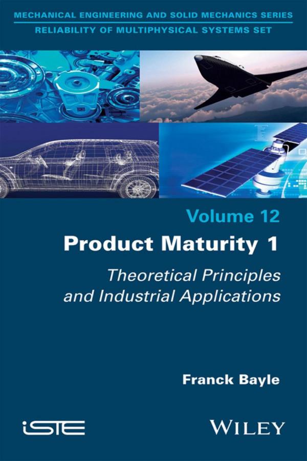
MJ is also known as polyjet multi-material process, and it is a similar method to the 2D inkjet printer that uses either a continuous or drop on demand (DOD) approach to build the 3D model. In MJ, a printhead dribbles the droplets of a photosensitive material to solidify layer by layer under UV light [30]. Acrylics, the thermoset photopolymers available in a liquid form, are considered the most common material for the MJ 3D printing process. The multi-material process is rare both with conventional methods and 3D printing technologies; without multi-material capabilities, prototyping and manufacturing can become expensive and time-consuming operations [31]. In general, the product of this process is divided into individual pieces, one for each material and color, thereby making the prototype efficient, fast, and inexpensive as shown in Figure 1.7.
The well-known commercial user of this process, polyjet konnex, uses a unique 3D printing technology with three operating modes: (i) The mixed part fabricates the
Figure 1.7 Schematic of the material jetting (MJ) process cured with the help of a UV lamp.
1.2 lassificationofAMProcesses 11 parts with a variety of materials; as a result, this mode eliminates the need to produce multiple parts and assembly; (ii) Digital materials are a combination of two or three polyjet resins blend to print parts. The printing yields a wide selection of composite materials with varying physical and visual properties [32]; and (iii) The mixed tray mode print several parts, each made with a different material at a time. This improves the response time and operation efficiency of the polyjet 3D printer. However, this process of 3D printing has one major difference from single material 3D printing. To print a multi-material, each area must be designated as a discrete shell in the CAD software. To generate these shells, the part must be segmented into different bodies, one for each material within the 3D CAD model, before it is converted to STL file format. The files are then imported to polyjet processing software, where the materials are assigned to 3D print followed by printing and finally to wash away the support material. Several companies use a multi-material 3D printer to simulate rubber products like gaskets, tires, and footwear soles with digital material that range from as soft as a rubber band to as hard as a shopping cartwheel. The use also extends to combine a rubber-like material with rigid plastics and to print product cast from a mold, like a toothbrush, razors, and power tools with soft-touch gripper surface. Even this process is suitable to make prototypes of products that have opaque and transparent properties, such as eyewear, display panels, anatomical models, and medical devices [33]. The 3D-printed part of this process is used as an end product such as in jigs and fixtures, artistic pieces, or some special items and gaming figures by many commercial users [34]. The use of a polyjet multi-material throughout the product lifecycle conveys design intent with realistic concepts models, with the analysis of form fit and function with prototypes that simulate material properties [35]. As a result, many companies reported savings of 50–90% when compared with using traditional prototyping methods. These progressive advances increase the productivity, as this can be fabricated in one step by eliminating the length and most direct labor expenses. Additionally, this process also minimizes secondary operations such as painting and assembly. All the advances allow the designers to explore more iterations on the lifelike product in less time, which means the errors are detected far earlier in this process.
1.2.5 Sheet Lamination
The SHL process was first commercialized in the year 1991; this process works either using laminated object manufacturing (LOM) or ultrasonic additive manufacturing (UAM). Figure 1.8 shows that LOM technology is a RP process that develops a model by using paper, plastic, or metal laminates that are successively glued together, and the desired shape of the object or model is cut using the laser cutter. The following are the steps for the LOM process [36]:
1) The sheet is joined to a substrate with a heated roller.
2) Laser traces desired dimension of the model or prototype.
3) The laser removes the area which is not part of the object.
Figure 1.8 Schematic of the laminated object manufacturing (LOM) process.
4) Platform with the completed layer moves down.
5) A fresh sheet of metal is rolled into the position.
6) The platform goes back to its original position to receive the next layer.
7) The process is repeated until the model or prototype is completed.
The sheets or ribbons of metals are used in the UAM process, and bonding takes place with the help of ultrasonic welding. This method does not require additional CNC machining and eliminating the unbound metal during the welding process. LOM is a layer-by-layer method, wherein the material used is paper and the welding is replaced by an adhesive. Several cutting strategies have been developed in the SHL process; the sheets are either cut and stacked or stacked and cut. To achieve adequate bonding, this process follows four different bonding mechanisms: (i) Gluing or adhesive bonding is the most popular technique that uses polymer-based adhesive to bond paper-build material. Commonly, the thickness of the paper ranges from 0.07 to 0.2 mm. Any material capable of cutting precisely using a laser or mechanical cutter can utilize this adhesive technique for part construction [36, 37]. (ii) Thermal bonding has been successfully applied by many commercial users around the world. Many researchers also demonstrated the flexibility of this method; for instance, 1 mm metal sheet fabricated by diffusion bonding is tested for physical discontinuity; the result is surprising that there is no break in grain structure throughout the sheet interfaces [38, 39]. (iii) Sheet metal clamping is the simple and most advantageous approach since the process involves just clamping the sheet together with bolts and nuts or another clamping mechanism instead of using adhesive or thermal bonding [40]. The clamping area can also be the reference point for successive laminates. The significant advantage of this process is that it is inexpensive and can adjust the cross-section of special laminates. However, the laminate clamp force may leave gaps when the pressurized polymers are injected into the mold. (iv) UAM, commonly known as ultrasonic consolidation, also called as the hybrid SHL process, uses a metal sheet layer to weld and CNC milling to fabricate the desired model. In general, the basic principle of this process involves the object being built on a heated platen
1.2 lassificationofAMProcesses 13
rigidly bolted, with a temperature range approximately equal to 200 °C [41]. The part approaches the bottom-up method for fabrication, and each layer comprises the number of metal foils laid side by side and subsequently for the trimming process by CNC milling. Earlier, 1 kW power is enough for materials like aluminum and copper, but currently, the machines are equipped with a 9 kW power system to process stainless steel and materials like Inconel [42]. Unlike LOM, the machining process is necessary to remove unwanted material since the metal is not easy to remove by hand. The main advantage is that the process requires bare minimum energy since after melting the metal, the process combines ultrasonic frequency and pressure to fabricate the part. Additionally, overhanging parts can also be possible from this technique; embedded electronics and wiring are other advances of this process. However, there are some difficulties as the consumption of the whole sheet to print a single layer leads to wastage of the material. As a result, printing certain geometries are impossible because of the unfeasibility of removing the unexploited material. Still, several articles reported safety care due to a possibility of fire after cutting paper and other flammable materials using lasers.
1.2.6 Direct Energy Deposition
The DED process is often referred to as metal deposition technology; although materials like polymer and ceramic matrix are suitable, this process is primarily used for metal powders. In contrast to the PBF process, the DED techniques melt the material deposited rather than just melting the material in a pre-laid situation. Also, this technique works similar to the MEX process; the three-dimensional part has been built using a converged heat source like a laser or electron beam, as represented in Figure 1.9. The DED process comprises various terminology, for instance, direct metal deposition, directed light fabrication, laser-engineered net shaping, and 3D laser cladding. In general, this printing process is considered more complex by increasing additional materials for the remaining components [25]. The basic working principle of a typical DED machine involves using
Final object optics
Feedback sensor 1Feedback sensor 2
Co2 laser beam
Power feeder
Solid freeform by DED
Substrate or die
Fixture
the material in any of the two forms: wire or powder. Among the two, the use of the wireform material is more efficient than the powder-form material, because only required material is used; even so, the wire material is less accurate due to a pre-defined shape. The material coming out from the nozzle is similar to that in the MEX process; in contrast, the nozzle is mounted on multiple axis arms to move in multiple directions. The nozzle can deposit the material at every angle owing to four and five axis machines; the material is then melted upon the specified surface to solidify with the help of a heat source such as a laser or electron beam at a controlled oxygen level. Nevertheless, in four or five axis machines, the flow rate will not change concerning the movement of the feed head as compared to static vertical deposition [43].
Concurrently, there is a possibility to assemble the system in such a manner as having an immovable arm and the build platform as movable and vice versa subject to particular application and the object printed [44]. Typically, the material cools rapidly in a temperature and time range from 1000 to 5000 °C/s. As a result, the material grain structure remains uniform but with irregular microstructure, including a layer thickness of 0.25–0.5 mm. This process has several advances, for instance, consistency in the similarity of grain microstructure and the ability of design freedom by adjusting the power of feed mixtures and process parameters to change the material and solidify the part comfortably [27]. Additionally, to improve the performance and lifetime of the building part, the process finely deposits a thin layer of metal upon the specified surface to make them corrosion and wear-resistant. However, there are some difficulties to achieve built part quality, such as poor resolution and surface finish due to restriction in parameters, accuracy not exceeding 25 mm, and roughness values of less than 25 μm are hard to print using the DED process.
1.2.7 VAT Polymerization
VAT polymerization, also called photopolymerization, is typically a very complex process among all AM processes, as shown in Figure 1.10. In general, the primary material used for this process involves liquid, radiation-curable resins, or photopolymers. Most photopolymers use UV radiation of a specified wavelength to react with resin; however, the use of UV radiation depends on the application and accuracy required; other radiations such as visible light, gamma rays, X-rays, and electron beams have also been shown to yield better results. The photopolymers are made of different materials like photoinitiator, stabilizers, liquid monomers, flexibilizers, and reactive diluents. When exposed to UV light, the photoinitiator inside the photopolymers undergoes a chemical shift and combines with the monomer to produce a chain of polymers [45]. Polymers are covalent, which means that they are bonded at the molecular level such that they have a stronger bond than the layers printed on FDM [46].
However, this does not mean that FDM is not strong enough; here, we are just comparing the stronger layer. In this process, three alternative formations are possible such as (i) vector scan or pointwise, (ii) mask projection or layer-wise, and (iii) twophoton polymerization approaches. The vector scan method, which is classified as specialized stereolithography (SL), employs either a top-down or bottom-up technique.

The bottom-up approach is often called inverted SL. In general, the 3D printing process uses UV rays to cure liquid resin to harden the plastic. Depending on the machine used, the resin is either manually poured into the resin path or automatically dispensed from the cartridge [25]. At the beginning of the process, the built platform is lowered into the resin, leaving a very thin space between the layer and bottom of the tank. The galvanometer directs the UV rays to the transparent window at the bottom of the resin tank, thus drawing the cross-section of the 3D model and selectively hardening the material. The print is built layer by layer, each less than 100 μm thick. When a layer is complete, the part is peeled from the bottom of the tank letting the fresh resin flow beneath, and the platform is lowered once again. Whereas in the mask projection approach, this process hardens the entire layer rather than hardening a tiny bit of resin at a time [27]. The laser uses optics to selectively block out the light except for a specific area and then uses digital light processing (DLP) to harden the layer. Finally, the two-photon approach is used, which is expensive and has limited consumer use at the moment. Following the 3D model, locally induced photopolymerization solidifies the material bypassing the ultra-short pulse striking out from the laser. Once the layer is printed, the focal plane moves to the next layer. The actual 3D capability of the method is to eliminate the need to deposit the material layer by layer. Due to non-linear absorption, spatial resolution in the submicron range can be achieved. Although there is a discrepancy from the approaches above, recoating on two photon-polymerization is unnecessary since the part is fabricated below the resin, whereas in the vector scan and mask projection approach, recoating or applying a new layer is a must to produce an object. From a machine design perspective, the method that eliminates the recoating process is more rapid and less intricate. However, because of limitations in chemistries, the use of photopolymers is restricted only to acrylates and epoxies. Additionally, the VP-printed products possess lesser impact strength and durability than injection-molded thermoplastics [47].