Instant download Rf filter technology for dummies, qorvo 2nd special edition david schnaufer pdf all
Visit to download the full and correct content document: https://ebookmass.com/product/rf-filter-technology-for-dummies-qorvo-2nd-special-ed ition-david-schnaufer/
More products digital (pdf, epub, mobi) instant download maybe you interests ...
Internet of Things For Dummies®, Qorvo 2nd Special Edition Cees Links & Tony Testa & John Anderton & Wilco Van Hoogstraeten & David Schnaufer & Cindy Warschauer
No part of this publication may be reproduced, stored in a retrieval system or transmitted in any form or by any means, electronic, mechanical, photocopying, recording, scanning or otherwise, except as permitted under Sections 107 or 108 of the 1976 United States Copyright Act, without the prior written permission of the Publisher. Requests to the Publisher for permission should be addressed to the Permissions Department, John Wiley & Sons, Inc., 111 River Street, Hoboken, NJ 07030, (201) 748-6011, fax (201) 748-6008, or online at http://www.wiley.com/go/permissions
Trademarks: Wiley, For Dummies, the Dummies Man logo, The Dummies Way, Dummies.com, Making Everything Easier, and related trade dress are trademarks or registered trademarks of John Wiley & Sons, Inc. and/or its affiliates in the United States and other countries, and may not be used without written permission. All other trademarks are the property of their respective owners. John Wiley & Sons, Inc., is not associated with any product or vendor mentioned in this book.
LIMIT OF LIABILITY/DISCLAIMER OF WARRANTY: WHILE THE PUBLISHER AND AUTHORS HAVE USED THEIR BEST EFFORTS IN PREPARING THIS WORK, THEY MAKE NO REPRESENTATIONS OR WARRANTIES WITH RESPECT TO THE ACCURACY OR COMPLETENESS OF THE CONTENTS OF THIS WORK AND SPECIFICALLY DISCLAIM ALL WARRANTIES, INCLUDING WITHOUT LIMITATION ANY IMPLIED WARRANTIES OF MERCHANTABILITY OR FITNESS FOR A PARTICULAR PURPOSE. NO WARRANTY MAY BE CREATED OR EXTENDED BY SALES REPRESENTATIVES, WRITTEN SALES MATERIALS OR PROMOTIONAL STATEMENTS FOR THIS WORK. THE FACT THAT AN ORGANIZATION, WEBSITE, OR PRODUCT IS REFERRED TO IN THIS WORK AS A CITATION AND/ OR POTENTIAL SOURCE OF FURTHER INFORMATION DOES NOT MEAN THAT THE PUBLISHER AND AUTHORS ENDORSE THE INFORMATION OR SERVICES THE ORGANIZATION, WEBSITE, OR PRODUCT MAY PROVIDE OR RECOMMENDATIONS IT MAY MAKE. THIS WORK IS SOLD WITH THE UNDERSTANDING THAT THE PUBLISHER IS NOT ENGAGED IN RENDERING PROFESSIONAL SERVICES. THE ADVICE AND STRATEGIES CONTAINED HEREIN MAY NOT BE SUITABLE FOR YOUR SITUATION. YOU SHOULD CONSULT WITH A SPECIALIST WHERE APPROPRIATE. FURTHER, READERS SHOULD BE AWARE THAT WEBSITES LISTED IN THIS WORK MAY HAVE CHANGED OR DISAPPEARED BETWEEN WHEN THIS WORK WAS WRITTEN AND WHEN IT IS READ. NEITHER THE PUBLISHER NOR AUTHORS SHALL BE LIABLE FOR ANY LOSS OF PROFIT OR ANY OTHER COMMERCIAL DAMAGES, INCLUDING BUT NOT LIMITED TO SPECIAL, INCIDENTAL, CONSEQUENTIAL, OR OTHER DAMAGES.
ISBN 978-1-119-89834-4 (pbk); ISBN 978-1-119-89835-1 (ebk)
For general information on our other products and services, or how to create a custom For Dummies book for your business or organization, please contact our Business Development Department in the U.S. at 877-409-4177, contact info@dummies.biz, or visit www.wiley.com/go/ custompub. For information about licensing the For Dummies brand for products or services, contact BrandedRights&Licenses@Wiley.com.
Publisher’s Acknowledgments
Some of the people who helped bring this book to market include the following:
Project Editor: Elizabeth Kuball
Acquisitions Editor: Ashley Coffey
Editorial Manager: Rev Mengle
Senior Account Manager: Molly Daugherty
Production Editor: Tamilmani Varadharaj
Special Help: Stephanie Orr, Alexis Mariani, Cindy Warschauer, Faithe Wempen
Introduction
The implementation of 5G and wireless applications is accelerating worldwide, along with the drive to deliver high data rates and high data capacity. This creates new challenges for wireless technology in many radio frequency (RF) device applications, because these trends increase the probability of interference. To mitigate that interference, RF filter technology is a must.
Bulk acoustic wave (BAW) and surface acoustic wave (SAW) technologies are evolving to address these challenges. These filter technologies are advancing toward handling higher frequencies, smaller device sizes, and increased interference.
This book provides a solid basic tutorial to RF filter technologies like BAW and SAW. It looks at these technologies and what’s driving filter technology implementations, helping you understand the benefits that make it so necessary. It also surveys the current state of how system engineers are using filter technology, in both mature and cutting-edge applications. After reading this book, you’ll understand how RF filter technology is revolutionizing the electronics engineering industry — and how it will continue to do so going forward.
Foolish Assumptions
It has been said that most assumptions have outlived their usefulness, but we assume a few things nonetheless! Mainly, we assume that you’re a stakeholder in the technology or semiconductor industry with more than a passing interest in a technology like SAW and BAW. Perhaps you’re an engineer, a design architect, a technician, a technical leader, a salesperson, a technology student, or an investor. We also assume that you have some knowledge of semiconductor technologies. As such, this book is written primarily for somewhat technical readers like you.
If any of these assumptions describes you, then this book is for you! If none of these assumptions describes you, keep reading anyway. It’s a great book, and when you finish reading it, you’ll know enough about RF filter technology to be dangerous!
Icons Used in This Book
Throughout this book, we occasionally use icons to call attention to important information. You won’t see the typical cute grinning faces or other flashing emoticons, but you’ll definitely want to stop and pay attention! Here’s what you can expect.
Discover key definitions and essential takeaways.
Watch out for these pitfalls, downsides, and drawbacks.
Explore highly technical aspects that may appeal to your inner geek.
Beyond the Book
Although this book is full of good information, we could only cover so much in 48 pages! So, if you find yourself wanting more after reading this book, just go to www.qorvo.com/products/filtersduplexers, where you can get to more information about Qorvo’s RF filter technology and products.
IN THIS CHAPTER
» Getting to know RF filters
» Comparing SAW and BAW filters
» Identifying the temperature coefficient of a filter and Q factor
» Learning how the filter coupling coefficient affects performance
» Understanding filter packaging
Chapter 1
Exploring RF Filter Technology
The rapid growth in mobile wireless data in the last decade has created an ever-increasing demand for new spectrum bands and new technologies to accommodate the thirst for wireless capacity. This demand is not only driving wireless technology advancements, but also increasing the need for more enhanced radio frequency (RF) filter technology to help reduce system interference, increase RF range and receiver capabilities, and improve coexistence.
In this chapter, you find out how RF filters work and the technology variations used in today’s applications. This chapter kicks things off by presenting some basic facts about filters and the benefits they provide.
Uncovering the Basics of RF Filters
New to RF filter technology? Start here, with these important filter terms and concepts that will help you throughout this book.
» Attenuation: An amplitude loss, usually measured in decibels (dB), incurred by a signal after passing through an RF filter. When referenced outside of the filter’s passband, it is also referred to as rejection.
» Cutoff: The point at which a filter’s response has fallen by 3 dB.
» Insertion loss: A loss of signal power in the targeted passband of the filter.
» Isolation: Separation of one signal from another to prevent unintentional interaction between them. For example, you might separate transmit and receive signals to prevent their interaction.
» Passband: The region through which a signal passes relatively unattenuated.
» Q factor: Short for quality factor, the ratio of stored versus lost energy per oscillation cycle. It’s used to measure the selectivity of a resonant circuit.
» Ripple: The variation of insertion loss in the passband.
» Selectivity: A measurement of a filter’s capability to pass or reject specific frequencies relative to its center frequency. Selectivity is usually stated as the loss through a filter that occurs at some specified difference from the center frequency of the filter.
» Stopband: The band where the filter has reached its required out-of-band rejection, defined as a required number of decibels.
Figure 1-1 illustrates a typical RF filter response using the terms as outlined earlier.
FIGURE 1-1: A typical RF filter response.
A filter removes unwanted frequency components from a signal while preserving the desired frequency bandwidth. Four basic types of filters accept or reject signals in different ways, as shown in Figure 1-2:
» Low-pass filter: Allows all frequencies below a certain frequency to pass while rejecting all others (opposite of high pass)
» High-pass filter: Allows all frequencies above a certain frequency to pass while rejecting all others (opposite of low pass)
» Band-pass filter: Allows all frequencies between two frequencies to pass while rejecting all others (opposite of band stop)
» Band-reject filter (also known as band-stop or notch): Rejects all frequencies between two frequencies while passing all others (opposite of band pass)
FIGURE 1-2: A basic RF filter and response.
Comparing Filter Technologies
Depending on application, a filter’s construction will vary. The most common differentiators in RF filter technology are size, cost, and performance. The filter’s construction plays a big role in these differentiators. Here are some examples of RF filter constructions:
» Acoustic filter: A filter capable of meeting both low and high frequencies up to 9 gigahertz (GHz), and in some special cases up to 12 GHz. These are small in size and offer the best combination of performance and cost for complex filter requirements. Acoustic filters are the most common filter construction for commercial RF microwave applications such as cellular, Wi-Fi, and Global Positioning System (GPS).
» Cavity filter: A filter used only in infrastructure applications. They can achieve good performance at reasonable cost but are larger than acoustic filters.
» Discrete inductor-capacitor (LC) filter: A low-cost structure of modest performance and size. The LC elements are sometimes implemented as printed structures on substrates called an integrated passive device (IPD). LC filters can also be implemented with discrete service mount device (SMD) components.
» Monoblock ceramic filter: A more expensive, higherperformance filter than multilayer ceramic. They’re also physically larger and usually aren’t suitable for mobile applications.
» Multilayer ceramic filter: A low- to medium-cost filter with performance similar to that of LC filters. Its footprint is generally reasonable, but its thickness is greater, limiting its use in some applications.
Filters can be designed to meet a variety of requirements. Although they use the same basic circuit configurations, circuit values differ when the circuit is designed to meet different criteria. In-band ripple, fastest transition to the ultimate roll-off, and highest outof-band rejection are some of the criteria that result in different circuit values.
Filters allow only particular frequencies or bands of frequencies to pass through and are an essential tool for RF design engineers.
Exploring Piezoelectric Acoustic Filters
The most preferred filter technology used in many of today’s applications are piezoelectric. These RF filters are small, costeffective solutions used in many commercial, military, and scientific applications.
The piezoelectric effect is a reversable phenomenon of physics. The crystal substance generates electricity when under mechanical stress, and the reverse is true as well. The crystal will stretch by a tiny amount when an electric field or voltage is applied. The piezoelectric materials convert applied mechanical stress into electrical energy and can also transform electrical energy into mechanical strain.
The two acoustic filters on the market are surface acoustic wave (SAW) and bulk acoustic wave (BAW).
As shown in Figure 1-3, SAW and BAW filters can be divided into two topologies: ladder and lattice. Ladder-type filters present a steep rejection near the passband, but poor out-of-band rejection. Lattice-type filters provide good out-of-band rejection with less steep rejection near the passband. A hybrid ladder-lattice configuration offers a compromise between rejection and passband steepness.
FIGURE 1-3: SAW and BAW configuration designs.
SAW filters
SAW filters are widely used and very mature. They laterally propagate high-frequency waves. As shown in Figure 1-4, an electrical input signal is converted to an acoustic wave by interleaved metal interdigital transducers (IDTs) created on a piezoelectric substrate like quartz, lithium tantalite (LiTaO3), or lithium niobate (LiNbO3). A SAW filter’s low velocity enables it to fit many wavelengths across the IDTs in a very small device.
FIGURE 1-4: A basic SAW RF filter.
A key advantage of SAW is its capability to optimally address standard filter applications from 600 to 1900 megahertz (MHz). It not only meets the low 5G bands at 600 MHz but also works well and is cost-effective in the low cellular bands of 1, 5, 8, 13, as well as the GPS bands.
To reach above 1900 MHz, layered SAW technologies — such as low-loss resonator technology (LRT), thin-film-SAW (TF-SAW), ultra-SAW, or incredibly high performance (IHP) SAW — are used. These technologies enable layered SAW to meet up to 2.7 gigahertz (GHz) for mid- to high-band applications. Above 2.7 GHz, SAW filter selectivity declines. However, where the SAW filter ends in performance, the BAW filter (covered later in this chapter) begins.
Temperature-compensated SAW
Among the many innovations in SAW technology is temperaturecompensated SAW (TC-SAW). This type of SAW uses a thermocompensated layer to avoid thermal drift, as shown in Figure 1-5. It performs at a higher level than standard SAW because of the greater temperature stability.
TC-SAW devices on single crystal lithium niobate, along with burying the IDT electrodes in a layer of silicon dioxide (SiO2), improves TCF and quality factor compared to traditional SAWbased filters and duplexers.
Implementing a temperature coefficient on SAW requires isolating the interdigital transducer (IDT) from any environmental temperature changes. To accomplish this, the SAW structure is covered with SiO2 and sometimes an additional silicon nitride layer, as shown on the right side of Figure 1-5.
FIGURE 1-5: SAW versus TC-SAW.
TC-SAW improves filter characteristics to deal with the tight band allocations of LTE and 5G, as well as carrier aggregation (CA) for uplink and high-power user equipment (HPUE). Those improvements include lower insertion loss, steeper skirt characteristics, temperature stability, higher power durability, wider bandwidth frequency range, higher linearity, smaller size, and integration. To achieve these characteristics, a higher Q factor and a small temperature coefficient of frequency (TCF) are essential.
Layered SAW
In a traditional SAW substrate configuration, the acoustic wave propagating along the surface reaches up to a few wavelengths under the electrodes, and bulk wave radiation patterns appear deep into the substrate. This causes bulk acoustic wave leakage, reducing Q factor, TCF, and coupling.
One way to reduce this leakage is to create a new, multilayered structure or a variation of TC-SAW, such as layered SAW, as shown in Figure 1-6. Adding this additional layer of SiO2 under the surface of the piezoelectric layer and functional layer provides an important benefit: A SAW propagating on the surface is guided in the piezoelectric layer and functional layer. As a result, the acoustic energy is confined in the vicinity of the surface, which improves the TCF and Q factor.
FIGURE 1-6: Layered-SAW versus SAW.
There are a few types of SAW filters on the market. They’re known as SAW, TC-SAW, and layered SAW, which are also known as guided-SAW, LRT-SAW, TF-SAW, ultra-SAW, and IHP-SAW. They’re all part of the family of SAW, using a layer
like SiO2 between the substrate and functional layer, as shown in Figure 1-6. Throughout this book, we refer to this type as layered SAW.
Layered SAW offers higher performance than the standard SAW filter. In some frequency bands, the layered SAW performance can even compete with BAW filters, discussed next.
Layered SAW technology relies on piezoelectric material deposited on an insulator. In layered SAW, the thermal compensation mechanism comes directly from the substrate instead of being deposited on the surface over the electrodes.
Table 1-1 compares the different characteristics of acoustic-based SAW RF filter technologies.
Qualitative Comparison of SAW Filter Technologies
BAW filters
The alternative to SAW is BAW. BAW filters address the frequencies between 1.4 and 9 GHz.
The main difference between BAW and SAW, besides the structure, is the piezoelectric material that the filters rely on. BAW filters use polycrystalline aluminum nitride, which provides higher coupling coefficient and higher wave velocity in the material.
TABLE 1-1
BAW filters can achieve very low loss because their acoustic energy density is very high, and the structures trap acoustic waves very well. Plus, their achievable Q factor is higher than other filter types of reasonable size employed at microwave frequencies. This results in superb rejection and insertion loss performance, even at the critical passband edges.
The BAW filter offers lower insertion loss, which helps contribute to longer battery life in smartphone applications. BAW also excels in applications where the uplink and downlink separation is minimal and when attenuation is critical in tightly packed adjacent bands.
Unlike SAW filters, the acoustic wave in a BAW filter propagates vertically. As shown in Figure 1-7, the resonator uses a quartz crystal as the substrate. Metal paths on the top and bottom sides of the quartz excite the acoustic waves, which bounce from the top to the bottom surface to form a standing acoustic wave. The thickness of the slab and the mass of the electrodes determine the frequency at which resonance occurs. At the high frequencies in which BAW filters are effective, the piezo layer must be only micrometers thick, requiring the resonator structure to be made using thin-film deposition and micro-machining on a carrier substrate.
To keep the waves from escaping into the substrate in this type of filter, an acoustic Bragg reflector is created by stacking thin layers of alternating stiffness and density. The result of this approach is called a solidly mounted resonator (SMR) BAW, as shown in Figure 1-7.
FIGURE 1-7: A basic BAW RF filter.
A Bragg reflector is a structure formed from multiple layers of alternating materials with varying refractive index.
There are two major types of BAW filters on the market, as shown in Figure 1-8: a solidly mounted resonator (SMR) BAW and a poly film bulk acoustic resonator (FBAR).
From a technology perspective, the big differentiators are substrate and air cavity between the substrate and bottom electrode. In Table 1-2, you see that stacked-layer BAW has the best temperature compensation.
TABLE 1-2 Qualitative Comparison of BAW and FBAR Filter Technologies
Some companies use their own brand names for FBAR or BAW technology, but they all fall under one of the two categories (BAW or FBAR). For example, XBAW is just another FBAR, while ultraBAW is another BAW.
XBAR is a shear-wave BAW technology that is laterally field coupled. However, this technology is still in development and is not available in product.
Discovering the Temperature Coefficient of Filters
It seems each year brings new spectrum allocations in cellular, Wi-Fi, automotive, and so on. These additions of spectrum are good news, because they drive incremental improvements in wireless devices. But this additional spectrum sometimes comes at a price in areas where bands overlap each other. There is also an increase in system heat due to the additional RF pathways.
To ensure these signal paths are properly isolated from each other, RF filters with a low temperature coefficient are used. But not just any filter will do in many of these applications where spectrum is closely aligned to each other. As shown in Figure 1-9, cellular and Wi-Fi bands are sometimes close to each other — separated by only a few megahertz. RF filter technology like BAW is used to ensure coexistence between these bands.
FIGURE 1-9: Examples of closely aligned Wi-Fi and cellular spectrum.
In both SAW and BAW technologies, a best-in-class temperature coefficient is vital. It can mean the difference between RF interference and good signal quality in an application. In BAW and SAW technologies, the filter response moves depending on temperature, as shown in Figure 1-10.
As application temperature changes the filter response, the filter bandwidth drifts right when cold and left when hot. A filter’s temperature drift is determined by the parts per million per degrees Celsius (ppm/°C) characteristic of the process and the temperature excursion the filter experiences in the application, as shown in Figure 1-10.
The frequency and environmental conditions of an application are usually fixed, so the only way to minimize the temperature drifting of the filter is via process technology. Using a temperature compensation (TC) filter process technology can affect the overall response of the filter. As you can see in Figure 1-10, the TCSAW, layered SAW, and BAW technology processes greatly reduce temperature drift of the individual filters. These BAW, layered SAW, and TC-SAW process technologies offer lower insertion losses, create steeper filter skirts, and provide better temperature responses — which all equate to better out-of-band attenuation during temperature shifts. They also improve receiver sensitivity, isolation, and rejection.
BAW filters are inherently less sensitive to temperature change than SAW filters. Temperature compensation (TC-SAW and TC-BAW) reduces temperature sensitivity even further.
In BAW, certain design techniques can be used to create a TC-BAW-type outcome, but generally BAW is effective when it comes to good temperature coefficient values. However, because of the structure makeup, there are differences between the three types of BAW when addressing the temperature coefficient.
FIGURE 1-10: Temperature drift of piezoelectric filters.
Figure 1-11 illustrates that the air cavity will likely affect the path of heat dissipation, thereby affecting the filter’s temperature coefficient. The advantages of BAW over FBAR are more pronounced at the higher frequencies used in 5G and Wi-Fi. Power handling in filters becomes more challenging at the higher frequencies due to the smaller resonator size. However, with BAW, the reflector layers also become thinner, which further improves heat extraction.
In contrast, with FBAR, the membrane above the air cavity becomes thinner, reducing its capability to move heat away from the resonator. As a result, with insertion loss as a constant between BAW and FBAR, the temperature rises 20°C per watt of transmit power, compared to 70°C rise per watt with FBAR. Less temperature variation means better performance, which enables BAW filters to meet system requirements for insertion loss and outof-band attenuation under high-power and high temperature conditions. Moreover, BAW filters have a low insertion loss due to their high Q factor and high coupling, which help reduce dissipated power and associated thermal issues.
Temperature challenges are also becoming constrained by today’s high frequencies and smaller size applications. Moreover, the higher the frequency of a design, the greater the challenge of meeting parameter requirements. One of those key parameters is insertion loss. Line lengths, matching components, filter components, and connecting trace lines have an added effect on insertion loss. This is especially true in frequencies above 3 GHz. To optimize a system’s link budget, low insertion loss filters are required.
FIGURE 1-11: BAW versus FBAR filter power and heat handling.
Evaluating the Q Factor
Multiple factors determine a filter’s insertion loss. Among these are the filter bandwidth relative to center frequency, the order of the filter, and the Q factor of the resonators that make up the component. The Q factor is a measure of the selectivity of a resonant circuit.
As shown in Figure 1-12, Resonator loss and coupling are the keys to low insertion loss and high selectivity. Resonators with similar coupling and impedance can be compared in performance by their Q factors.
FIGURE 1-12: Q factor, bandwidth, and attenuation characteristics of an RF filter.
Exploring the Filter Coupling Coefficient
In filter technology, the two performance parameters that drive application performance are the filter coupling coefficient and the Q factor.
The RF filter resonator coupling coefficient plays a key role in determining the bandwidth of an acoustically coupled filter. Increasing the coupling effectiveness for a BAW filter resonator in an SMR or FBAR configuration can offer low insertion loss and high performance in a small package size.
Effective coupling coefficient (K2eff) is a measurement of the relative spacing between the resonance frequency (ƒs) and anti-resonance frequency (ƒp). Its value depends upon a multitude of factors, including the electrode and the piezoelectric characteristics.
The electromechanical coupling coefficient is the measure of the efficiency of the piezoelectric device in converting electrical energy to mechanical energy and vice versa. The mutual energy, or energy capable of conversion, is the elastic energy and dielectric energy. To maximize the filter resonator’s coupling coefficient, it’s crucial to provide the reflection of the acoustic energy as close to the resonator as possible.
In the BAW filter, the effective coupling coefficient of the resonators defines the obtainable flat passband width of the filter.
Understanding Filter Packaging
The surface area of the radio frequency front end (RFFE) is shrinking in many (if not all) applications. This change is driven mostly by device size reductions and the need to make room for more consumer features.
Most of what we see today are module and monolithic integration, or the combination of both, inside one package. Figure 1-13 illustrates a highly integrated module that includes power amplifiers, BAW filters, and antenna switches. This, in turn, is incorporated into a complex system in package (SiP). This is just one of the complex modules that would be housed inside one SiP in normal applications.
FIGURE 1-13: Complex RF module inside of SiP.
IN THIS CHAPTER
» Understanding the crowded spectrum
» Identifying which filter works in what application
» Explaining multiplexers and antennaplexers
Chapter 2
Discovering the RF Front End and Filters
Filter technology is critical to mitigating crosstalk interference, maintaining peak signal performance, and optimizing system efficiency in gateways, cell phones, and other wireless devices. Without these filters, designers would struggle to meet many required system-level specifications that provide ubiquitous, always-on connectivity.
Filters make such a difference in today’s end-product design because they help system engineers mitigate or entirely remove system-level challenges. Additionally, filters can reduce design time by creating viable go-to solutions for system designers.
In this chapter, you see how applications are driving a new era in radio frequency (RF) filter design in the RF front end (RFFE). You find out about families of filters and begin to explore duplexers, multiplexers, and antennaplexers, and see how they’re used in today’s applications.
Exploring the RFFE and RF Filter
The rapid growth of spectrum and the many frequency bands to accommodate the speeds and capacity requirements — along with the integration of new technologies like ultra-wideband (UWB)
and cellular vehicle to everything (C-V2X) — are driving filter technology to help coexistence between many frequency bands. As a core component of the RFFE, RF filters are widely used in base stations, automotive, Wi-Fi, wireless communications, and more. In the following sections, we dig deeper into the technical aspects of filter technology and how it relates to the RFFE.
Understanding the role of duplexing
Duplexing enables two-way communications over a single communication channel. There are two basic modes of duplex operation:
» Half-duplex: The communicating parties take turns transmitting and receiving. While one party is transmitting, the other is receiving.
» Full-duplex: The communicating parties can transmit and receive simultaneously.
Full duplexing is achieved through frequency division duplexing (FDD), and half duplexing is achieved through time division duplexing (TDD), as shown in Figure 2-1.
FIGURE 2-1: FDD versus TDD uplink and downlink.
FDD uses two separate frequency bands or channels to achieve full duplex communications. The two bands are physically separated in frequency (called a duplex gap) to prevent interference.
TDD emulates full-duplex communication over a half-duplex link, using a single frequency band for both transmitting and receiving.
TDD assigns rapidly alternating time slots to transmit and receive operations of the communicating devices. Although TDD transmissions are concurrent rather than simultaneous, the intermittent nature of the communication is imperceptible to the communicating parties due to the high speeds at which TDD occurs.
Explaining isolation and cross-isolation
Duplexers are commonly used in FDD radio applications, where one filter is a transmit (Tx) filter and the other filter is a receive (Rx) filter. Duplexers are designed so that the passbands of each filter will not load the other.
Isolation is a measure of the amount of power that leaks from one RF port path to another. The greater the isolation between these RF pathways, the lower the leakage. If the isolation is low, then signals can bleed into one another causing interference, or desense (short for desensitization) in the case of the receiver.
The transmit signal appearing at the output of the receive filter must be significantly attenuated. This high level of isolation is required so that the signal doesn’t overdrive the receiver’s front end. This is often referred to as transmit-receive isolation, and values of 55 decibels (dB) or higher are common.
There must also be high Tx-to-Rx isolation at the receive frequency. This is to prevent noise at wide offsets from the transmit signal (that is, at the receive frequency) from appearing at the receiver input and degrading sensitivity. These two isolation requirements form the in-band isolation.
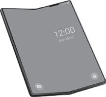
Isolation between RF pathways gets more challenging with each wireless device generation. For example, some smartphone models are now foldable, as shown in Figure 2-2. Not only are the phones incorporating numerous antennas to provide services in cellular, Wi-Fi, Global Positioning System (GPS)/Global Navigation Satellite System (GNSS), UWB, millimeter wave (mmWave), and Bluetooth ranges, but they’re also challenged because now these pathways are folding over each other, making the possibility of interference more likely. This makes isolation between these RF pathways, standards, and closely aligned antennas even more important. RF filter designers must work even more diligently to meet more stringent isolation, passband, and attenuation parameters to ensure these foldable phones work without interference.
Looking into RF receiver desense and sensitivity
Receiver sensitivity is the minimum detectable receiving signal power of a digital radio receiver. If a wireless receiver is desensitized, it means the noise floor is increased due to electromagnetic interference. This interference reduces the received signal-tonoise ratio, degrading the receiver performance throughput versus range.
Maintaining receiver performance amid RF interference and high receiving signal power is a major requirement for radio receivers.
Desense is the degradation in receiver sensitivity due to noise sources, which are typically generated by the same device radio it’s in. Desense is caused by electromagnetic interference, which can come from an internal source or a strong self-generated interference within the system itself. Most often, the interference is self-generated.
The ideal filter would have 0 dB insertion loss in its passband and negative-infinity dB in its stop band. Between the passband and stop band would be a transition from 0 dB to negative infinity.
FIGURE 2-2: Foldable phones with multiple antennas.
It would pass the required frequencies without adding or subtracting anything from the RF signal. However, a perfect filter like this can’t be attained. Real-world filters have insertion loss, passband ripple, and nonzero gain in the stop band (refer to 1-1 in Chapter 1).
The transition band can be a defining characteristic in a filter’s usefulness in a given application. The transition band is the steepness of the roll-off between the passband and the stop band.
The selectivity of a receiver is also very important. With the many RF signals being transmitted, the radio receiver must be able to receive only the required signal frequency and reject the unwanted signals. The receiver selectivity performance determines the level of interference the receiver will experience. Therefore, it’s very important that the receiver rejects unwanted frequencies to enable interference-free performance.
Selectivity refers to the capability to filter out signals. In an RFFE receiver, selectivity is the capability to reject adjacent unwanted signals. Having superior insertion loss and out-of-band attenuation improves the isolation between signals on the receiver. High isolation between signal paths is also critical in limiting intermodulation products and meeting out-of-band emission specifications. Receiver filter performance is key when defining the selectivity.
Selectivity of a filter is also closely related to the quality factor (Q factor). Reducing the bandwidth of a filter increases its Q factor. The skirts become steeper, and the filter becomes more selective. Therefore, the band pass filter increases in selectivity as the Q factor increases. In general, designing a filter with superior selectivity is a trade-off between steep skirts, insertion loss, and Q factor.
The capability for a receiver to discriminate between signals is imperative. Receiver selectivity is usually discussed in terms of adjacent channel rejection (ACR), adjacent channel selectivity (ACS), in-band blocking, and out-of-band blocking.
Navigating a crowded spectrum
As we continue to jam more bands into the already crowded RF space, the space continues to get squeezed. In some cases, the transition between the passband and stop band is as small
as 2 megahertz (MHz). This makes it challenging to meet system-level requirements. Any variation in filter response, which is dominated by temperature drift, can exceed the width of the transition band itself. This can result in interference, low signal quality, or both. This is where filters attribute the most. Figure 2-3 shows an example of how RF filters help separate Wi-Fi and the vehicle to everything (V2X) bands. Using filters with steep out-of-band transitions are a must in these types of situations.
FIGURE 2-3: Spectrum of Wi-Fi and V2X bands.
Because spectrum is a scarce resource, governments must ration it. This forces RF system designers to bear the brunt of the challenge in their designs, such as mitigating the evolving capabilities of several spectrum areas like Wi-Fi, automotive, Internet of Things (IoT), and cellular, all of which are converging upon each other as spectrum evolves. These technology bands require steep curve filters with little temperature drift and superior insertion loss to separate their signals or otherwise risk RF interference.
Learning how small device applications affect filter design
All wireless device solutions are shrinking in size. Today the Wi-Fi home and business architectures are called distributed Wi-Fi or Wi-Fi mesh. They’re based on a “pod per room” architecture and are becoming more commonplace. These Wi-Fi pod access points or mesh network devices are becoming sleeker and smaller. In mobile smartphones, RF area is shrinking to accommodate larger batteries, more cameras, and more RF pathways. In wireless infrastructure towers, the RF portion is moving toward the top of the tower with the antenna, requiring the RFFE to be smaller and meet higher transmit and receive performance.
For example, the printed circuit board (PCB) in a smartphone is shrinking because of several factors. Phone manufacturers
have increased battery size to support new features like additional cameras and antennas for UWB, mmWave, and diversity functions. To support the broad range of frequencies for Wi-Fi, low-band, mid-band, high-band, ultra-high-band, UWB, and mmWave, more antennas are required — up to six in many of today’s smartphones (see Figure 2-4). This is forcing RFFE system designers to create smaller front-end components, including filters, in addition to integrating these filters inside small RFFE modules.
FIGURE 2-4: Larger batteries in 5G phones reduce the PC board space.
With the addition of all the new antennas to accommodate the many new and existing bands, high antenna performance is required. For high antenna performance, adequate antenna volume and spacing is required — and this is happening while space is becoming constrained.
Manufacturers face a tough architectural decision to meet this requirement previously solved using separate filters. They can try to add more antennas in an ever-shrinking area, with potential reduction in antenna and system-level performance. Or they can use a new development in design. This is where antennaplexers come into play — we delve more into that topic in Chapter 4.
Briefly speaking, antennaplexers combine multiple RF filters to allow several different radios — like cellular Wi-Fi, GPS, and UWB — to share a single antenna. They enable mobile devices to use the existing antenna area more efficiently, adding support for new bands with no impact on existing form factors or features. Antennaplexers reduce the need to have separate antennas, while addressing coexistence filtering and insertion loss requirements, as shown in Figure 2-5.
FIGURE 2-5: This antennaplexer enables a single antenna to be shared with Wi-Fi and cellular mid-bands and ultra-high bands.
Wi-Fi RFFE manufacturers are also taking advantage of front-end module technology to shrink the form factor, reduce the number of matching components, decrease the PC board space area, and create smaller, sleeker devices. By using front-end modules incorporating many RF pathways, as shown in Figure 2-6, system designers can save costs, cut design times, and get products to market more quickly.
Wi-Fi RF front-end module with filters.
Adding multiple-input/multiple-output (MIMO) and higher frequencies in the 6 GHz realm has increased system temperature in Wi-Fi gateways. With more thermal and coexistence requirements, robust RFFE components that support high temperatures and multiple frequency ranges have become a must.