https://ebookmass.com/product/pyroelectric-materialsphysics-and-applications-ashim-kumar-bain/
Instant digital products (PDF, ePub, MOBI) ready for you
Download now and discover formats that fit your needs...
3D and 4D Printing of Polymer Nanocomposite Materials: Processes, Applications, and Challenges 1st Edition Kishor
Kumar Sadasivuni
https://ebookmass.com/product/3d-and-4d-printing-of-polymernanocomposite-materials-processes-applications-and-challenges-1stedition-kishor-kumar-sadasivuni/ ebookmass.com
Class 8th Physics book 1st Edition Pawan Kumar
https://ebookmass.com/product/class-8th-physics-book-1st-editionpawan-kumar/
ebookmass.com
Wide Bandgap Semiconductor Power Devices_ Materials, Physics, Design, and Applications B. Jayant Baliga
https://ebookmass.com/product/wide-bandgap-semiconductor-powerdevices_-materials-physics-design-and-applications-b-jayant-baliga/ ebookmass.com
The Excellent Mind: Intellectual Virtues for Everyday Life
Nathan L. King
https://ebookmass.com/product/the-excellent-mind-intellectual-virtuesfor-everyday-life-nathan-l-king/
ebookmass.com
Rethinking Cybercrime: Critical Debates Tim Owen
https://ebookmass.com/product/rethinking-cybercrime-critical-debatestim-owen/
ebookmass.com
Blowin' Up A Murder (Kenni Lowry Mystery Book 8) Tonya Kappes
https://ebookmass.com/product/blowin-up-a-murder-kenni-lowry-mysterybook-8-tonya-kappes/
ebookmass.com
Interventions et Thérapies Brèves : 10 Stratégies Concrètes. Crises et Opportunités 2e édition Edition Betbèze
https://ebookmass.com/product/interventions-et-therapiesbreves-10-strategies-concretes-crises-et-opportunites-2e-editionedition-betbeze/
ebookmass.com
Data Communications and Networking 5th Edition
https://ebookmass.com/product/data-communications-and-networking-5thedition/
ebookmass.com
Contemporary Issues on Governance, Conflict and Security in Africa Adeoye O. Akinola
https://ebookmass.com/product/contemporary-issues-on-governanceconflict-and-security-in-africa-adeoye-o-akinola/
ebookmass.com
Abrams’ Clinical Drug Therapy: Rationales for Nursing Practice 11th Edition, (Ebook PDF)
https://ebookmass.com/product/abrams-clinical-drug-therapy-rationalesfor-nursing-practice-11th-edition-ebook-pdf/
ebookmass.com
PyroelectricMaterials
PyroelectricMaterials
PhysicsandApplications
AshimKumarBain PremChand
Authors
Prof.AshimKumarBain UniversityofBirmingham Electronic,Electrical&SystemsEngin. B152TTEdgbaston UnitedKingdom
Prof.PremChand IITKanpur DepartmentofPhysics 208016Kanpur India
CoverImage: ©JoseA.Bernat Bacete/GettyImages
Allbookspublishedby WILEY-VCH arecarefully produced.Nevertheless,authors,editors,and publisherdonotwarranttheinformation containedinthesebooks,includingthisbook, tobefreeoferrors.Readersareadvisedtokeep inmindthatstatements,data,illustrations, proceduraldetailsorotheritemsmay inadvertentlybeinaccurate.
LibraryofCongressCardNo.: appliedfor BritishLibraryCataloguing-in-PublicationData Acataloguerecordforthisbookisavailable fromtheBritishLibrary.
Bibliographicinformationpublishedby theDeutscheNationalbibliothek TheDeutscheNationalbibliotheklists thispublicationintheDeutsche Nationalbibliografie;detailedbibliographic dataareavailableontheInternetat <http://dnb.d-nb.de>.
©2023WILEY-VCHGmbH,Boschstraße12, 69469Weinheim,Germany
Allrightsreserved(includingthoseof translationintootherlanguages).Nopartof thisbookmaybereproducedinanyform–by photoprinting,microfilm,oranyother means–nortransmittedortranslatedintoa machinelanguagewithoutwrittenpermission fromthepublishers.Registerednames, trademarks,etc.usedinthisbook,evenwhen notspecificallymarkedassuch,arenottobe consideredunprotectedbylaw.
PrintISBN: 978-3-527-35101-5
ePDFISBN: 978-3-527-83972-8
ePubISBN: 978-3-527-83973-5
oBookISBN: 978-3-527-83974-2
Typesetting Straive,Chennai,India
Contents
Preface ix
1FundamentalsofDielectrics 1
1.1Dielectrics 1
1.1.1PolarizationofDielectrics 2
1.1.2DispersionofDielectricPolarization 3
1.1.2.1ElectronicPolarization 3
1.1.2.2IonicPolarization 4
1.1.2.3OrientationPolarization 4
1.1.2.4SpaceChargePolarization 4
1.1.3DielectricRelaxation 5
1.1.4DebyeRelaxation 6
1.1.5MolecularTheoryofInducedChargesinaDielectric 6
1.1.6CapacitanceofaParallelPlateCapacitor 7
1.1.7ElectricDisplacementField,DielectricConstant,andElectric Susceptibility 9
1.1.8LocalFieldinaDielectric 10
1.1.8.1LorentzField, E2 11
1.1.8.2FieldofDipolesInsideCavity, E3 11
1.1.9DielectricsLosses 12
1.1.9.1DielectricLossAngle 13
1.1.9.2TotalandSpecificDielectricLosses 14
1.1.10DielectricsBreakdown 15 References 16
2Pyroelectricity 19
2.1Introduction 19
2.2HistoryofPyroelectricity 21
2.3TheoryofPyroelectricity 32
2.4SimpleModelofPyroelectricEffect 33
2.5PyroelectricCrystalSymmetry 36
2.6Piezoelectricity 37
2.7Ferroelectricity 39
2.7.1FerroelectricPhaseTransitions 40
2.7.2FerroelectricDomains 42
2.7.3FerroelectricDomainWallMotion 42
2.7.4SoftMode 45
2.7.4.1Zone-centerPhonons 46
2.7.4.2Zone-boundaryPhonons 46 References 47
3PyroelectricMaterialsandApplications 55
3.1Introduction 55
3.2TheoryofPyroelectricDetectors 57
3.3MaterialFigure-of-Merits 62
3.4ClassificationofPyroelectricMaterials 62
3.4.1SingleCrystals 63
3.4.1.1TriglycineSulphate 63
3.4.1.2LithiumTantalate(LT)andLithiumNiobate(LN) 67
3.4.1.3BariumStrontiumTitanate(BST) 72
3.4.1.4StrontiumBariumNiobite(SBN) 75
3.4.2PerovskiteCeramics 77
3.4.2.1ModifiedLeadZirconate(PZ) 78
3.4.2.2ModifiedLeadTitanate(PT) 85
3.4.3OrganicPolymers 87
3.4.4Ceramic-PolymerComposites 90
3.4.5Lead-FreeCeramics 96
3.4.6OtherPyroelectricMaterials 97
3.4.6.1AluminumNitride(AlN) 98
3.4.6.2GalliumNitride(GaN) 102
3.4.6.3ZincOxide(ZnO) 103 References 108
4PyroelectricInfraredDetector 119
4.1Introduction 119
4.2DeviceConfigurations 120
4.2.1ThickFilmDetectors 120
4.2.2ThinFilmDetectors 123
4.2.3HybridFocalPlaneArrayDetector 126
4.2.4LinearArrayDetector 127
4.2.4.1DetectorChipTechnology 127
4.2.4.2DetectorAssembly 129
4.2.4.3CameraSystem 129
4.2.5PeriodicDomainTFLTTM Detector 131
4.2.5.1TFLTTM PyroelectricDetectorFabrication 132
4.2.5.2TFLTTM AttachedtoMetalizedSilicon 134
4.2.5.3TFLTTM onCeramic 135
4.2.5.4LargeApertureDevices 136
4.2.5.5DomainEngineeredTFLTTM Device 137
4.2.6TerahertzThermalDetector 139
4.2.7PVDFPolymerDetector 140
4.2.7.1Self-absorbingLayerStructure 140
4.2.7.2PVDFPyroelectricSensorAssembly 141
4.2.7.3SensorArraySpecificationandPerformance 142
4.2.8TFPPolymerDetector 143
4.2.9Tetraaminodiphenyl(TADPh)PolymerDetector 146
4.2.9.1DetectorDesign 147
4.2.9.2DetectorSensitivity 147
4.2.10IntegratedResonantAbsorberPyroelectricDetector 148
4.2.10.1DetectorDesign 149
4.2.10.2DetectorSensitivity 150
4.2.11ResonantIRDetector 150
4.2.11.1PrinciplesofOperationofResonantDetector 151
4.2.11.2IRAbsorbingCoatingsandStructures 152
4.2.11.3DifferentialOperationandDetectorArrays 154
4.2.11.4PerformanceofGaNResonators 155
4.2.12PlasmonicIRDetector 155
4.2.12.1StructureDesign 156
4.2.12.2FabricationandPerformanceoftheDetector 158
4.2.13GraphenePyroelectricBolometer 161
4.2.13.1DeviceArchitecture 163
4.2.13.2DevicePerformance 164 References 165
5PyroelectricEnergyHarvesting 173
5.1Introduction 173
5.2TheoryofPyroelectricEnergyHarvesting 175
5.3PyroelectricityinFerroelectricMaterials 178
5.3.1ThermodynamicCyclesofPyEH 178
5.3.1.1CarnotCycle 178
5.3.1.2EricssonCycle 179
5.3.1.3OlsenCycle 180
5.4PyroelectricGenerators 181
5.5PyroelectricNanogenerators 183
5.5.1Polymer-BasedPyroelectricNanogenerators 183
5.5.1.1PyNGsDrivenbyVariousEnvironmentalConditions 183
5.5.1.2DevelopmentofPyroelectricMaterials 186
5.5.1.3WearablePyroelectricNanogenerators 188
5.5.1.4HybridPyroelectricNanogenerators 191
5.5.2Ceramic-BasedPyroelectricNanogenerators 198
5.5.2.1ZnO-BasedPyroelectricNanogenerators 198
5.5.2.2PZT-BasedPyroelectricNanogenerators 201
viii Contents
5.5.2.3Lead-FreeCeramic-BasedPyroelectricNanogenerators 204
5.5.3ThermalNanophotonic-PyroelectricNanogenerators 208
5.5.4ChallengesandPerspectivesofPyroelectricNanogenerators 210 References 211
6PyroelectricFusion 221
6.1Introduction 221
6.2HistoryofPyroelectricFusion 221
6.3PyroelectricNeutronGenerators 224
6.4PyroelectricX-rayGenerators 229
6.4.1Applications 231
6.4.2Features 231 References 233
Index 237
Preface
PyroelectricitywasprobablyfirstobservedbytheGreeksmorethan24centuriesago. ThephilosopherTheophrastuswrotethat lyngourion (mostlikelythemineraltourmaline)hadthepropertyofattractingstrawsandbitsofwood.Fortwomillennia, thepeculiarpropertiesoftourmalineweremoreapartofmythologythanofscience. Intheeighteenthcentury,pyroelectricstudiesmadeamajorcontributiontothe developmentofourunderstandingofelectrostatics.Inthenineteenth,researchon pyroelectricityaddedtoourknowledgeofmineralogy,thermodynamics,andcrystal physics.Thefieldofpyroelectricityflourishedinthetwentiethcenturywithmany applications,particularlyininfrareddetectionandthermalimaging.Pyroelectric sensorshavebeencarriedinmanyspacemissionsandhavecontributedsignificantly toourastronomicalknowledge.
Recently,pyroelectricityhasbecomeoneofthemoststudiedphenomenainthe scientificcommunityduetothevariousapplicationsofpyroelectricmaterialsin electronicdevices.Thisbookdescribesthebasicphysicalproperties,structure,and applicationsofpyroelectricmaterials.
Thefirstchapter ofthisbookdealswiththebasicconceptsofdielectrics. Chapter2 describesthebasicconceptsofpyroelectricity,theoryofpyroelectricity, andhistoryofpyroelectricity.Chapter3 presentsthephysicalproperties,structure, andapplicationsofdifferentpyroelectricmaterialsdevelopeduptotherecent time.Chapter4 providesup-to-dateinformationonthedesignandapplicationsof variouspyroelectricIRdetectors.Chapter5 givesanoverviewoftheprogressin thedevelopmentofpyroelectricnanogenerators(PyNGs)foranenergyharvesting systemthatusesenvironmentalorartificialenergiessuchasthesun,bodyheat, andheaters. Thelastchapter discussesthelatestresearchresultsonpyroelectric fusionandprovidesinformationonnewlydesignedpyroelectricneutrongenerators andX-raygenerators(prototypeportable).
Isincerelyhopethatthisbookwillbeveryusefulforscientificcommunityincludingstudents,teachers,andresearchersworkinginthisfield.
Finally,IwouldliketothanktheWiley-VCHpublishingteamfortheiroutstanding support.
AshimKumarBain Birmingham,UK PremChand I.I.T.Kanpur,India
July2022
FundamentalsofDielectrics
1.1Dielectrics
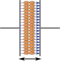
Adielectricmaterialisasubstancethatisapoorconductorofelectricity.Onthebasis ofbandstructure,thedielectricmaterialshaveanenergygapof3eVormore.This largemagnitudeofenergygapprecludesthepossibilityofelectronsbeingexcited fromthevalencebandtotheconductionbandbythermalmeans.Inelectromagnetism,adielectric(ordielectricmaterialordielectricmedium)isanelectricalinsulatorthatcanbepolarizedbyanappliedelectricfield.Whenadielectricmaterialis placedinanelectricfield,electricchargesdonotflowthroughthematerialasthey doinanelectricalconductor,butinsteadonlyslightlyshiftfromtheiraverageequilibriumpositions,causingdielectricpolarization(Figure1.1).Becauseofdielectric polarization,positivechargesaredisplacedinthedirectionofthefieldandnegative chargesshiftinthedirectionoppositetothefield(e.g.ifthefieldismovingparallelto thepositive x -axis,thenegativechargeswillshiftinthenegative x -direction).This createsaninternalelectricfieldthatreducestheoverallfieldwithinthedielectric itself.Ifadielectriciscomposedofweaklybondedmolecules,thosemoleculesnot onlybecomepolarizedbutalsoreorientsothattheirsymmetryaxesaligntothefield.
Thestudyofdielectricpropertiesconcernsstorageanddissipationofelectricand magneticenergyinmaterials[1,2].Dielectricsareimportantforexplainingvarious phenomenainelectronics,optics,solid-statephysics,andcellbiophysics[3,4].
Althoughtheterminsulatorimplieslowelectricalconduction,dielectrictypically meansmaterialswithahighpolarizability.Thelatterisexpressedbyanumbercalled therelativepermittivity.Theterminsulatorisgenerallyusedtoindicateelectrical obstruction,whilethetermdielectricisusedtoindicatetheenergy-storingcapacity ofthematerial(bymeansofpolarization).Acommonexampleofadielectricisthe electricallyinsulatingmaterialbetweenthemetallicplatesofacapacitor.Thepolarizationofthedielectricbytheappliedelectricfieldincreasesthecapacitor’ssurface chargeforthegivenelectricfieldstrength.
ThetermdielectricwascoinedbyWilliamWhewell(from dia + electric)in responsetoarequestfromMichaelFaraday[5,6].Aperfectdielectricisamaterial withzeroelectricalconductivity(cf.perfectconductorinfiniteelectricalconductivity),thusexhibitingonlyadisplacementcurrent;therefore,itstoresandreturns electricalenergyasifitwereanidealcapacitor.
PyroelectricMaterials:PhysicsandApplications,FirstEdition.AshimKumarBainandPremChand. ©2023WILEY-VCHGmbH.Published2023byWILEY-VCHGmbH.
1.1.1PolarizationofDielectrics
Figure1.1 Apolarizeddielectric material.
Thefactorscontributingtothepolarizationofdielectricmoleculesareasfollows: theformationofdipolemomentsandtheirorientationrelativetotheelectricfield. If,inadielectric,themoleculesformingelementarydipolemomentsarecomposed ofneutralparticlessuchasatoms,theelectricfieldshiftstheelectricchargeofan atomicshellagainstthedirectionoffieldandthenucleusismovedinwiththefield. Thus,thecenterofgravityofthepositiveandnegativechargesisdisplacedfrom thecenteroftheatomandan“induceddipolemoment”isproduced,asshownin Figure1.2a.Thispartofpolarizationofmoleculesiscalled electronic (Pe ).Theelectronicpolarizationisindependentoftemperature,butitisdirectlyproportionalto thefieldstrength.
Ifthemoleculeproducinganelementarydipolemomentismadeofionsofoppositesigns,thefollowingprocessoccurswhenthedielectricisplacedintoanelectric field:thepositiveionsleavetheirequilibriumpositionsandmoveinthedirection offield,andthenegativeionsaredisplacedagainstthedirectionoffield.Thisdisplacementofionsortheirgroupsinadielectricinitiatesan ionic polarization(Pi ) ofmolecules,asshowninFigure1.2b.Theionicpolarizationisalsoindependentof temperature,butitdependsonthebindingenergyofparticlesinthemoleculeand inthelatticeofthedielectric.
Figure1.2 Polarization processes:(a)electronic polarization,(b)ionic polarization,(c)orientational polarization,and(d)space chargepolarization.
Theasymmetricdistributionofchargebetweendifferentatomsinamolecule producespermanentdipolemomentsinthemoleculesofadielectric.Underthe actionofanelectricfield,thesepermanentdipolesarerotatedintothedirectionof thefieldandthuscontributetopolarization.Inthiscase,wespeakaboutthe orientational polarization(Po ),asshowninFigure1.2c.Theorientationalpolarizationis dependentontemperature.Withincreasingtemperature,thethermalenergytends torandomizethealignmentofthepermanentdipolesinsidethematerials.
Inrealdielectrics,freechargesmayexist,which,undertheactionofanelectric field,movethroughthedielectricandarecapturedbyvariousdefectswithinthe dielectricwithoutcomingintocontactwiththeelectrodes.Thefreechargesthen formregionswithasurfaceoraspacecharge,whichinturnproducesadipole moment,alsocontributingtothepolarizationofadielectric.Thismechanisminitiatesa space(surface) chargepolarization(Ps )insidethedielectric,asshownin Figure1.2d.Liketheorientationalpolarization,thespacechargepolarizationisalso afunctionoftemperature,which,inmostcases,increaseswithtemperature.
Thetotalpolarizationofadielectricmaysimultaneouslyinvolveallthefour mechanisms.Ifweassumethattheyareindependent,wecanwritethetotal polarizationofadielectricmaterialasthesumofthecontributionsfromthefour sourcesdescribedearlier:
Ptotal = Pe + Pi + Po + Ps (1.1) wherethesubscriptsontherightrefertothefourtypes:electronic,ionic, orientational,andspacechargepolarization,respectively.
1.1.2DispersionofDielectricPolarization
Ingeneral,amaterialcannotpolarizeinstantaneouslyinresponsetoanappliedfield. Thedielectricpolarizationprocesscanbeexpressedasafunctionoftemperature. P(t)= P [1 exp ( t tr )] (1.2) where P isthemaximumpolarizationattainedonapplicationoftheelectricfield, and tr istherelaxationtimefortheparticularpolarizationprocess.Therelaxation time tr isthetimetakenforapolarizationprocesstoreach63%ofthemaximum value.
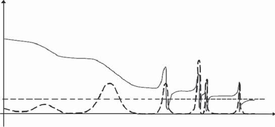
Therelaxationtimevarieswidelyondifferentpolarizationprocesses.Thereare anumberofpolarizationmechanisms,asshowninFigure1.3.Themostcommon, startingfromhighfrequencies,aregiveninthesubsequentsection.
1.1.2.1ElectronicPolarization
Thisprocessoccursinanatomwhentheelectricfielddisplacestheelectrondensityrelativetothenucleusitsurrounds.Electronicpolarizationmaybeunderstood byassuminganatomasapointnucleussurroundedbysphericalelectroncloudof uniformchargedensity.Electronshaveverysmallmassandarethereforeableto followthehigh-frequencyfieldsuptotheopticalrange.Itisanextremelyrapidprocessandisessentiallycompleteattheinstantthevoltageisapplied.Evenwhenthe
Figure1.3 Frequencydependenceofpolarizationdispersion. frequencyoftheappliedvoltageisveryhighintheopticalrange(∼1015 Hz),the electronicpolarizationoccursduringeverycycleoftheappliedvoltage.
1.1.2.2IonicPolarization
Thisprocessisassociatedwiththerelativemotionsofcationsandanionsinan electricfield.Ionicpolarizationisslowerthanelectronicpolarization,asthedisplacementinvolvedhereisthatofmuchheavierionascomparedtotheelectron cloud.Thefrequencywithwhichionscanbedisplacedoverasmallfractionofthe interatomicdistancewillbeofthesameorderasthelatticevibrationfrequency (∼1013 Hz).Ifanelectricfieldoffrequencyintheopticalrange(∼1015 Hz)isapplied, theionsdonotrespondatall,asthetimerequiredbyanionforonevibrationis 100timeslargerthantheperiodoftheappliedvoltage.Therefore,thereisnoionic polarizationatopticalfrequencies.
1.1.2.3OrientationPolarization
Itisslowerthanionicpolarization.Orientationpolarizationarisesfromtherotation ofmoleculardipolesinthefield.Itiseasierforthepolarmoleculestoreorientthemselvesinaliquidthaninsolid.Orientationpolarizationoccurswhenthefrequency oftheappliedvoltageisintheaudiorange.
1.1.2.4SpaceChargePolarization
Itistheslowestprocess,asitinvolvesthediffusionofionsoverseveralinteratomic distances.Therelaxationtimeforthisprocessisrelatedtothefrequencyofsuccessful jumpsofionsundertheinfluenceoftheappliedfield.Spacechargepolarizations oftenoccurinthekilohertzrangeorevenlower.
ReferringtoFigure1.3,allthefourtypesofpolarizationarepresentatmachine frequencies.Asthefrequencyincreases,spacecharge,orientation,andionicpolarizationbecomeinoperativeinthatorder.Whenseveralpolarizationprocessesoccur inamaterial,itfollowsthatthedielectricconstantwilldecreasewithincreasingfrequencyoftheappliedvoltage.Whentheperiodoftheappliedvoltageismuchlarger thantherelaxationtimeofapolarizationprocess,thepolarizationiscompletedat
anyinstantduringeachcycle,andwhentheperiodoftheappliedvoltageismuch shorterthantherelaxationtimeforapolarizationprocess,thepolarizationdoesnot occuratall.Butwhentheperiodoftheappliedvoltageisinthesamerangeasthe relaxationtime,resonanceoccurs.
Athighfrequencies,usuallymicrowaveandbeyond–theprocessesthattake placeareundampedandarecalled“resonances.”Realdielectricmaterialshave severalsuchresonancesduetoionicandelectronicpolarization.Atfrequencies belowmicrowaves,thepolarizationprocessesareheavilydampedandarecalled “relaxations.”Inphysics,dielectricdispersionisthedependenceofthepermittivity ofadielectricmaterialonthefrequencyofanappliedelectricfield.Thisisbecause thereisalagbetweenchangesinpolarizationandchangesintheelectricfield.The permittivityofthedielectricisacomplicatedfunctionoffrequencyoftheelectric field.Dielectricdispersionisveryimportantfortheapplicationsofdielectric materialsandfortheanalysisofpolarizationsystems.
Thisisoneinstanceofageneralphenomenonknownasmaterialdispersion: afrequency-dependentresponseofamediumforwavepropagation.
Whenthefrequencybecomeshigher:
● dipolarpolarizationcannolongerfollowtheoscillationsoftheelectricfieldinthe microwaveregionaround1010 Hz
● ionicpolarizationandmoleculardistortionpolarizationcannolongertrackthe electricfieldpasttheinfraredorfar-infraredregionaround1013 Hz
● electronicpolarizationlosesitsresponseintheultravioletregionaround1015 Hz.
Inthefrequencyregionaboveultraviolet,permittivityapproachestheconstant ��0 ineverysubstance,where ��0 isthepermittivityofthefreespace.Becausepermittivity indicatesthestrengthoftherelationbetweenanelectricfieldandpolarization,ifa polarizationprocesslosesitsresponse,permittivitydecreases.
Theeffectoftemperatureontherelativepermittivityofamaterialcanbetwofold. Inorientationpolarization,therandomizingactionofthermalenergydecreases thetendencyforthepermanentdipolestoalignthemselvesintheappliedfield. Thisresultsinadecreaseintherelativepermittivitywithincreasingtemperature. Theothereffectoftemperatureistofacilitatethediffusionofionsinspacecharge polarization.Thermalenergymayaidinovercomingtheactivationbarrierforthe orientationofrelativelylargepolarmoleculesinthedirectionofthefield.
1.1.3DielectricRelaxation
Dielectricrelaxationisthemomentarydelay(orlag)inthedielectricconstantofa material.Thisisusuallycausedbythedelayinmolecularpolarizationwithrespect toachangingelectricfieldinadielectricmedium(e.g.insidecapacitorsorbetween twolargeconductingsurfaces).Dielectricrelaxationinchangingelectricfieldscould beconsideredanalogoustohysteresisinchangingmagneticfields(e.g.ininductor ortransformercores).
Relaxationingeneralisadelayorlagintheresponseofalinearsystem,andtherefore,dielectricrelaxationismeasuredrelativetotheexpectedlinearsteadystate
(equilibrium)dielectricvalues.Thetimelagbetweenelectricalfieldandpolarization impliesanirreversibledegradationofGibbsfreeenergy.
Inphysics,dielectricrelaxationreferstotherelaxationresponseofadielectric mediumtoanexternal,oscillatingelectricfield.Thisrelaxationisoftendescribed intermsofpermittivityasafunctionoffrequency,whichcan,foridealsystems, bedescribedbytheDebyeequation.Ontheotherhand,thedistortionrelatedto ionicandelectronicpolarizationshowsbehavioroftheresonanceoroscillatortype. Thecharacterofthedistortionprocessdependsonthestructure,composition,and surroundingsofthesample.
1.1.4DebyeRelaxation
Debyerelaxationisthedielectricrelaxationresponseofanideal,noninteracting populationofdipolestoanalternatingexternalelectricfield.Itisusuallyexpressed inthecomplexpermittivity �� ofamediumasafunctionofthefield’sfrequency ��:
where ��∞ isthepermittivityatthehigh-frequencylimit(i.e., ��
where ��s isthestatic,low-frequency(i.e., �� → 0)permittivity,and �� isthecharacteristicrelaxationtimeofthemedium.Separatingintotherealpart ��′ andthe imaginarypart ��′′ ofthecomplexdielectricpermittivityyields[7]:
ThesearetheDebyeequations,andwefindthattheyarereasonablyapplicableto mostdispersionsatelectricalfrequencies.Thedielectriclossisalsorepresentedby:
ThisrelaxationmodelwasintroducedbyandnamedafterthephysicistPeter Debye[8].Itischaracteristicfordynamicpolarizationwithonlyonerelaxationtime.
1.1.5MolecularTheoryofInducedChargesinaDielectric
Adielectriccontainsnofreecharges;thenhowitispossibleforaninducedcharge toappearonthesurfaceofadielectricwhenplacedinanelectricfield?Thiscan beexplainedbythemolecularviewpointofdielectric.Thedielectricsareclassified intopolarandnonpolar.Anonpolarmoleculeisoneinwhichthecenterofgravityofpositiveandnegativechargesnormallycoincides,whileapolarmoleculeis onewheretheydonotcoincide.Polarmolecules,therefore,havepermanentdipole moments.Intheabsenceofanexternalfield,thesedipolesareorientedatrandom. Butstrongfieldorientsmoredipolesinthedirectionofthefield.Thechargesofa nonpolarmoleculesufferasmalldisplacementwhenplacedinanelectricfield.
Figure1.4 The depolarizationfield E 1 is oppositeto P .Thefictitious surfacechargesare indicated:thefieldofthese chargesis E 1 withinthe ellipsoid.
Themoleculesaresaidtobecomepolarizedbythefieldandarecalledinduced dipoles.Therefore,thedielectrics,bothpolarandnonpolar,behaveinthesameway undertheinfluenceofexternalelectricfield.Wecanimaginethatthesedipolesin theappliedelectricfieldcanhaveexcessnegativechargesononesurfaceandpositive chargesontheoppositesurface,asshowninFigure1.4.
Thesechargesarenotfree,buteachisboundtoamoleculelyinginornearthe surface.Thenetchargeperunitvolumewithintherestofthedielectricmediumis zero.Theelectricfield E1 setupbytheinducedchargealwaysopposestheapplied field E0 .Theresultantfield E isthevectorsumofthesetwo.Thatis,
Thefield E1 iscalledthedepolarizationfield;thisisbecausewithinthebody,it tendstoopposetheappliedfield E0 asshowninFigure1.4.Theresultantfield E pointstothesamedirectionas E0 butissmallerinmagnitude.Thisleadstotheconclusionthatifadielectricisplacedinanelectricfield,theinducedsurfacecharges appear,whichtendtoweakentheoriginalfieldwithinthedielectric.Thus,wecan definethedielectricconstant(k)orrelativepermittivity(��r )astheratioofthemagnitudeoftheappliedfield E0 totheresultantfield E.Then,
where V 0 isthepotentialdifferencewithoutanymediumand V isthesamewitha dielectricmediuminbetweenthecapacitorplates.
Therefore,forsamecharges Q,theratioofcapacitancewithdielectric C andcapacitancewithoutdielectric(forfreespace) C0 willbe
Fromtheabovedefinitionof k,thedielectricconstantorpermittivityforfreespace isunity.Obviously, k isadimensionlessquantity.
1.1.6CapacitanceofaParallelPlateCapacitor
Ifaconstantvoltage V 0 isappliedtoaplanecondenserwithavacuumcapacity C0 , acharge Q ofdensity �� = Q/A issetuponthecondenserwitharea A anddistanceof separation d betweentheplates(Figure1.4).FromtheapplicationofGauss’slaw,we knowthattheelectricfieldintensitybetweentwoplateswithavacuumis E = �� /��0 .
Thepotentialdifference V 0 istheworkdoneincarryingaunitchargefromone platetotheother.Hence, V0 = Ed = ( �� ��0 ) d = ( Qd ��0 A )
Rearrangingtherelation(1.9),wecanwrite
V0 = ( ��0 A d )
Thecapacitance C0 canbewrittenas:
0 = Q V0 = ( ��0 A d )
Thecapacitance C ofthecapacitorwithdielectricmediumcanbewrittenas: C = �� A d (1.13) where �� isthepermittivity(absolutepermittivity)ofdielectricmediumbetween thecapacitorplates.Thepermittivity(��)isoftenrepresentedbytherelativepermittivity(��r ),whichistheratiooftheabsolutepermittivity(��)andthevacuum permittivity(��0 ).
Rearrangingrelations(1.13)and(1.14),wecanwrite C = ��r ��0 ( A d ) = k��0 ( A d ) (1.15)
Relation(1.15)canbeexpressedintherationalizedformintheSIsystembythe formula:
C = ��r ��0 ( A d ) = ��r (8.854 × 10 12 ) ( A d ) F(1.16)
where d isinmetersand A isinsquaremeters.Normalizedunitsinthe cgs electrostaticsystemcanbeexpressedbytheformula:
C = ��r ( 1 4�� )( A d ) cm(1.17) where d isincentimetersand A insquarecentimeters.
SampleProblem1.1
Aparallel-platecapacitorofarea A = 4 × 10 2 m2 andplateseparation d = 2 × 10 2 m israisedtoapotentialdifference V 0 = 100Vbyconnectingabatterywhenthereis nodielectricinbetweentheplates.
(a)Calculatethecapacitance C0 ofthecapacitor.(b)Whatisthefreecharge appearedontheplates?
(a)FromEq.(1.12),thecapacitanceofthecapacitor:
C0 = ��0 A d = (8.85 × 10 12 F∕m)(4 × 10 2 m2 ) 2 × 10 2 m = 17.8 × 10 12 F = 17.8pF (Answer)
(b)FromEq.(1.12),thefreecharge:
SampleProblem1.2
Calculatethedielectricconstantofabariumtitanatecrystal,whichwheninserted inaparallelplatecapacitorofarea A = 10mm × 10mmanddistanceofseparation of d = 2mm,givesacapacitanceof10 9 F.
FromEq.(1.15),thedielectricconstantofthemediumbetweenthecapacitor plates:
SampleProblem1.3
Acapacitorof1nFisrequired.Ifadielectricmaterialofthickness0.1mmand relativepermittivity5.4isavailable,determinetherequiredplatearea.
FromEq.(1.15),theareaofthecapacitorplates:
1.1.7ElectricDisplacementField,DielectricConstant,andElectric Susceptibility
Inphysics,theelectricdisplacementfield(denotedby D)orelectricinductionisa vectorfieldthatappearsinMaxwell’sequations.Itaccountsfortheeffectsoffree andboundchargewithinmaterials.“D”standsfor“displacement,”asintherelated conceptofdisplacementcurrentindielectrics.Infreespace,theelectricdisplacementfieldisequivalenttofluxdensity,aconceptthatlendstheunderstandingof Gauss’slaw.
Inadielectricmaterial,thepresenceofanelectricfield E causestheboundcharges inthematerial(atomicnucleiandtheirelectrons)toslightlyseparate,inducinga localelectricdipolemoment.Theelectricdisplacementfield“D”isdefinedas:
D = ��0 E + P (1.18) where ��0 isthevacuumpermittivity(alsocalledpermittivityoffreespace),and P is the(macroscopic)densityofthepermanentandinducedelectricdipolemomentsin thematerial,calledthepolarizationdensity.
Inalinear,homogeneous,isotropicdielectricwithinstantaneousresponseto changesintheelectricfield, P dependslinearlyontheelectricfield, P = ��0 χE (1.19) wheretheconstantofproportionality �� iscalledtheelectricsusceptibilityofthe material.Now,rearrangingrelations(1.18)and(1.19),wecanwrite
D = ��0 (1 + �� )E = ��E (1.20)
where �� = ��0 ��r isthepermittivity,and ��r = (1 + �� )istherelativepermittivityofthe material.
Inalinear,homogeneous,andisotropicmedia, �� isaconstant.However,in alinearanisotropicmedia,itisatensor,andinnonhomogeneousmedia,itis afunctionofpositioninsidethemedium.Itmayalsodependupontheelectric field(nonlinearmaterials)andhaveatime-dependentresponse.Explicittime dependencecanariseifthematerialsarephysicallymovingorchangingintime (e.g.reflectionsoffamovinginterfacegiverisetoDopplershifts).Adifferentform oftimedependencecanariseinatime-invariantmedium,astherecanbeatime delaybetweentheimpositionoftheelectricfieldandtheresultingpolarizationof thematerial.Inthiscase, P isaconvolutionoftheimpulseresponsesusceptibility �� andtheelectricfield E.Suchaconvolutiontakesonasimplerforminthefrequency domain:byFouriertransformingtherelationshipandapplyingtheconvolution theorem,oneobtainsthefollowingrelationforalineartime-invariantmedium:
where �� isthefrequencyoftheappliedfield.Theconstraintofcausalityleads totheKramers–Kronigrelations,whichplacelimitationsupontheformofthe frequencydependence.Thephenomenonofafrequency-dependentpermittivityis anexampleofmaterialdispersion.Infact,allphysicalmaterialshavesomematerial dispersionbecausetheycannotrespondinstantaneouslytoappliedfields,butfor manyproblems(thoseconcernedwithanarrowenoughbandwidth),thefrequency dependenceof ε canbeneglected.
1.1.8LocalFieldinaDielectric
Wenowdevelopanexpressionforthelocalfieldatagenerallatticesite,notnecessarilyofcubicsymmetry.Toevaluate Eloc ,wemustcalculatethetotalfieldacting onacertaintypicaldipole;thisfieldisduetotheexternalfieldaswellasall other dipolesinthesystem.ThiswasdonebyLorentzasfollows:thedipoleisimagined tobesurroundedbyasphericalcavitywhoseradius R issufficientlylargethatthe matrixlyingoutsideitmaybetreatedasacontinuousmediumasfarasthedipoleis concerned(Figure1.5a).Theinteractionofourdipolewiththeotherdipoleslying insidethecavityis,however,tobetreatedmicroscopically,whichisnecessarysince thediscretenatureofthemediumveryclosetothedipolesshouldbetakeninto account.Thelocalfield,actingonthecentraldipole,isthusgivenbythesum
Eloc = E0 + E1 + E2 + E3 (1.22) where E0 istheexternalfield; E1 isthedepolarizationfield,thatis,thefieldduetothe polarizationchargeslyingattheexternalsurfacesofthesample; E2 isthefielddue tothepolarizationchargeslyingonthesurfaceoftheLorentzsphere(Figure1.5b), whichisknownasLorentzfield;and E3 isthefieldduetootherdipoleslyingwithin thesphere.
Itisimportanttonotethatthepartofthemediumbetweenthesphereandthe externalsurfacedoesnotcontributeanythingsincethevolumepolarizationcharges
Figure1.5 (a)Theprocedureforcomputingthelocalfield.(b)Theprocedurefor calculating E 2 ,thefieldduetothepolarizationchargeonthesurfaceoftheLorentzsphere.
compensateeachother,resultinginazeronetchargeinthisregion.Thecontribution E1 + E2 + E3 tothelocalfieldisnothingbutthetotalfieldatoneatomcausedbythe dipolemomentsofalltheotheratomsinthespecimen.Dipolesatdistancesgreater thanperhaps10latticeconstantsfromthereferencesitemakeasmoothlyvarying contribution.Itisconvenienttolettheinteriorsurfacebespherical.
1.1.8.1LorentzField, E 2
ThepolarizationchargesonthesurfaceoftheLorentzcavitymaybeconsideredas formingacontinuousdistribution.Thefieldduetothechargeatapointlocatedat thecenterofthesphereis,accordingtoCoulomb’slaw,givenby
1.1.8.2FieldofDipolesInsideCavity, E 3
Thefield E3 duetothedipoleswithinthesphericalcavityistheonlytermthat dependsonthecrystalstructure.Forareferencesitewithcubicsurroundingsin asphere, E3 = 0ifalltheatomsmaybereplacedbypointdipolesparalleltoeach other.Thetotallocalfieldatacubicsiteisthen,
Thisisknownas Lorentzrelation.ThedifferencebetweentheMaxwell’sfield E andtheLorentzfield Eloc isasfollows:thefield E ismacroscopicinnatureandis anaveragefield.Ontheotherhand, Eloc isamicroscopicfieldandisperiodicin nature.Thisisquitelargeatmolecularsites,indicatingthatthemoleculesaremore effectivelypolarizedthantheyareundertheinfluenceofMaxwell’sfield E
Ifthereare n moleculesoratomsperunitvolumeinadielectric,thentheelectric dipolemomentperunitvolumeis n�� Eloc ,representedby P,knownaspolarization. Therefore,
1FundamentalsofDielectrics
where �� isaconstantandisknownaspolarizabilityofthedielectricmaterial. Rearrangingrelations(1.24)and(1.25),wecanwrite
Thepolarizationisinducedbyelectricfield,andtherefore,itisafunctionofelectricfield.Therelationshipiswritteninthefollowingway:
where �� iscalledthedielectricsusceptibility.Ingeneral, �� isatensoranddepends ontheelectricfield.Thedielectricsusceptibility �� isdefinedintermsofrelative permittivity ��r ofthematerial.
Now,rearrangingrelations(1.26–1.28),wecanwriteanexpressionintermsofthe relativepermittivity:
Theaboveequationisknownas Clausius–Mossottirelation.Thisrelatestherelativepermittivitytopolarizabilityofthedielectricmaterial.Thetotalpolarizability �� canbewrittenasthesumoffourterms,representingthemostimportantcontributionstothepolarization,thatis, �� = �� e + �� i + �� o + �� s ,where �� e , �� i
,and ��
arethe electronic,ionic,orientational,andspacechargepolarizabilities,respectively.
Since ��r = k = n2 ,wecanrewriterelation(1.29)asfollows:
Thisisthe Lorentz–Lorenz equation.Itconnectstheindexofrefraction(n)with thepolarizability.
1.1.9DielectricsLosses
Whenanelectricfieldactsonanymatter,thelatterdissipatesacertainquantity ofelectricenergythattransformsintoheatenergy.Thisphenomenonisknown asthelossofpower,meaninganaverageelectricpowerdissipatedinmatter duringacertainintervaloftime.Asarule,thelossofpowerinaspecimenofa materialisdirectlyproportionaltothesquareoftheelectricvoltageappliedtothe specimen.
Ifametalconductorisfirstconnectedtodirectvoltageandthentoalternating voltage,theactingmagnitudeofwhichisequaltodirectvoltage,thelossofpower P inwattswillbethesameinbothcasesinconformitywiththeJoule–Lenzlawand equalto P = V 2 R (1.31) where V isthevoltageinvoltsand R istheresistanceoftheconductorinohms.
Asdistinctfromconductors,mostofthedielectricsdisplayacharacteristicfeature: underagivenvoltage,thedissipationofpowerinthedielectricsdependsonthe voltagefrequency;theexpenseofpoweratanalternatingvoltageismarkedlyhigher thanthatatadirectvoltage;rapidlygrowswithanincreaseinfrequency,voltage,and capacitance;anddependsonthematerialofthedielectric.
Thepowerlossesinadielectricundertheactionofthevoltageappliedtoitare commonlyknownas dielectriclosses.Thisisthegeneraltermdeterminingtheloss ofpowerinanelectricalinsulationatbothadirectandanalternatingvoltage.Dielectriclossesatadirectvoltagecanbefoundfromrelation(1.31)where R standsforthe resistanceoftheinsulation,whilethelossesunderthealternatingvoltagearedeterminedbymoreintricateregularities.Actually,thedielectriclossesmeanthelosses ofpowerunderanalternatingvoltage.
1.1.9.1DielectricLossAngle
ThephasediagramofcurrentsandvoltagesinacapacitorenergizedbyanalternatingvoltageisshowninFigure1.6.Ifthepowerwasnotdissipatedatallinthe dielectricofthecapacitor(idealdielectric),thephaseofcurrent I throughthecapacitorwouldbeaheadofthephaseofvoltage V by90∘ ,andthecurrentwouldbepurely reactive.Inactualfact,thephaseangle �� isslightlylessthan90∘ .Thetotalcurrent I throughthecapacitorcanberesolvedintotwocomponents:active I a andreactive I r currents.
Thus,thephaseangledescribesacapacitorfromtheviewpointoflossesinadielectric.Sincethephaseangle �� isverycloseto90∘ inacapacitorwithahigh-quality dielectric,theangle �� (i.e. �� = 90∘ ��)isamoredescriptiveparameter,whichis calledthe dielectriclossangle.Thetangentoftheangleisequaltotheratioofthe activecurrentstothereactivecurrents:
ortheratioofactivepower
(powerloss)tothereactivepower
Thedielectriclossangleisanimportantparameterforthedielectricmaterials. Thisparameterisusuallydescribedbythelosstangenttan �� .Sometimes,thequality factorofaninsulationportionisdetermined,thatis,thevalueisreciprocaloftheloss tangent:
Figure1.6 Phasediagramofcurrent andvoltageinacapacitorwitha dielectricmaterial.
Thevaluesoftan �� forthebestelectricalinsulatingmaterialsemployedin high-frequencyandhigh-voltageengineeringpracticeareoftheorderofthousands andevententhsofthousandsoffractions.
1.1.9.2TotalandSpecificDielectricLosses
Thevalueofdielectriclosses P inaninsulatingmaterialhavingacapacitance C is describedfromrelation(1.31)asfollows:
P = VIa = VIr tan ��
Insertingtheintensityofthecapacitivecurrentthroughaninsulationportionwith acapacitanceof C,weget
Since �� = 2�� f ,theangularfrequency,thedielectriclosses P canbeexpressedas follows:
Insertingthevalueofeffectivelength Λ= A/d inEq.(1.36)andreplacing ��0 byits numericalvalue
theexpressionofdielectriclossescanbeformulatedas:
Formulas(1.36)and(1.37)haveabroadfieldofapplication.Theyholdforanysize andshapeofaninsulatedportion.
Theknowledgeoftotalamountofdielectriclossesintheinsulatedportionisnot enough,anditisnecessarytostudythedistributionofdielectriclossesattheseparate pointsofinsulation.Letusconsideracubewithedge dx insidetheinsulatedportion inwhichweareinterestedsothatthelinesofforcespiercethecubeenteringand leavingitthroughtwooppositefacesinthedirectionperpendiculartothesefaces (Figure1.7).
Figure1.7 Electricfieldpiercesa cubewithedge dx inaninsulated portion.