Applications of Polymer Nanofibers
Edited by Anthony L. Andrady
Department of Chemical and Biomolecular Engineering, North Carolina State University, Raleigh, NC, USA
Saad A. Khan
Department of Chemical and Biomolecular Engineering, North Carolina State University, Raleigh, NC, USA
This edition first published 2022 © 2022 John Wiley & Sons, Inc.
All rights reserved. No part of this publication may be reproduced, stored in a retrieval system, or transmitted, in any form or by any means, electronic, mechanical, photocopying, recording or otherwise, except as permitted by law. Advice on how to obtain permission to reuse material from this title is available at http://www.wiley.com/go/permissions.
The right of Anthony L. Andrady and Saad A. Khan to be identified as the authors of the editorial material in this work has been asserted in accordance with law.
Registered Office
John Wiley & Sons, Inc., 111 River Street, Hoboken, NJ 07030, USA
Editorial Office
111 River Street, Hoboken, NJ 07030, USA
For details of our global editorial offices, customer services, and more information about Wiley products visit us at www.wiley.com.
Wiley also publishes its books in a variety of electronic formats and by print-on-demand. Some content that appears in standard print versions of this book may not be available in other formats.
Limit of Liability/Disclaimer of Warranty
In view of ongoing research, equipment modifications, changes in governmental regulations, and the constant flow of information relating to the use of experimental reagents, equipment, and devices, the reader is urged to review and evaluate the information provided in the package insert or instructions for each chemical, piece of equipment, reagent, or device for, among other things, any changes in the instructions or indication of usage and for added warnings and precautions. While the publisher and authors have used their best efforts in preparing this work, they make no representations or warranties with respect to the accuracy or completeness of the contents of this work and specifically disclaim all warranties, including without limitation any implied warranties of merchantability or fitness for a particular purpose. No warranty may be created or extended by sales representatives, written sales materials or promotional statements for this work. The fact that an organization, website, or product is referred to in this work as a citation and/or potential source of further information does not mean that the publisher and authors endorse the information or services the organization, website, or product may provide or recommendations it may make. This work is sold with the understanding that the publisher is not engaged in rendering professional services. The advice and strategies contained herein may not be suitable for your situation. You should consult with a specialist where appropriate. Further, readers should be aware that websites listed in this work may have changed or disappeared between when this work was written and when it is read. Neither the publisher nor authors shall be liable for any loss of profit or any other commercial damages, including but not limited to special, incidental, consequential, or other damages.
Library of Congress Cataloging-in-Publication Data applied for: ISBN: 9781119267683
Cover Design: Wiley
Cover Images: Image of silver-silica hybrid nanofibers courtesy of Tahira Pirzada; Images of Elecrospun fibers of polymers of intrinsic microposity courtesy of Siyao Wang; Wiley (Advanced Functional Materials, Cellulose Silica Hybrid Nanofiber Aerogels, 2020) Tahira Pirzada Set in 9.5/12.5pt STIXTwoText by Straive, Pondicherry, India
This volume is dedicated to the first responders and medical personnel worldwide, working tirelessly to contain the Covid-19 pandemic
Contents
List of Contributors xiii
Preface xvi
1 Electrospinning Parameters and Resulting Nanofiber Characteristics: Theoretical to Practical Considerations 1 Christina Tang, Shani L. Levit, Kathleen F. Swana, Breland T. Thornton, Jessica L. Barlow, and Arzan C. Dotivala
1.1 Electrospinning Overview 1
1.2 Effect of Process Parameters 2
1.2.1 Theoretical Analysis 2
1.2.2 Experimental Results 5
1.3 Effect of Setup Parameters 6
1.4 Effect of Solution Parameters 11
1.4.1 Polymer Solution Properties (Molecular Weight, Concentration, Viscosity, and Elasticity) 11
1.4.2 Solvent Selection 14
1.4.3 Additivities to Tune Solution Properties 16
1.4.3.1 Surface Tension 16
1.4.3.2 Conductivity 16
1.5 Electrospinnable Systems 17
1.5.1 Nonpolymer Electrospinning 18
1.6 Advanced Fiber Characteristics 20
1.6.1 Ribbons, Wrinkles, Branching, and Netting 20
1.6.2 Porous Fibers 21
1.6.3 Core–Shell Fibers 24
1.6.3.1 Coaxial Electrospinning 24
1.6.3.2 Emulsion Electrospinning 25
1.7 Process Scalability 26
1.7.1 Melt Electrospinning 26
1.7.2 Needleless or “Free-Surface” Electrospinning 29
1.7.3 Alternative Fiber Production Methods 30 References 32
2 Textile Applications of Nanofibers 41
Jiadeng Zhu, Yeqian Ge, and Xiangwu Zhang
2.1 Introduction of Nanofibers in Textile Applications 41
2.2 Fabrication of Nanofiber Yarns 42
2.2.1 Electrospinning 42
2.2.2 Bicomponent Spinning 43
2.2.3 Melt Blowing 44
2.2.4 Flash Spinning 44
2.2.5 Centrifugal Spinning 45
2.2.6 Formation of Nanofiber Yarns 45
2.3 Structure and Properties of Nanofiber Yarns 47
2.4 Fabrication of Nanofiber Fabrics 52
2.4.1 Nanofibrous Nonwoven Fabrics 52
2.4.2 Nanofibrous Woven Fabrics 54
2.5 Characteristics and Specialized Applications of Nanofiber Fabrics 57
2.5.1 Protective Clothing 57
2.5.2 Filter Fabrics 58
2.5.3 Wearable Devices 59
2.5.4 Functional Fabrics 60
2.5.5 Biomedical Textiles 61
2.6 Summary and Future Trends 61 References 62
3 Nanofiber Mats as High-Efficiency Filters 68 Howard J. Walls and David S. Ensor
3.1 Introduction 68
3.1.1 Background 68
3.1.2 Filtration Overview 69
3.1.3 Available Information 70
3.1.4 Scope of This Chapter 70
3.2 Filters Made with Nanofibers 72
3.2.1 Consequences of Reducing Fiber Size 72
3.2.2 Slip Flow 73
3.2.3 Pressure Drop 74
3.2.4 Particle Collection Mechanisms 76
3.2.5 Evaluation 81
3.2.6 Nanofiber Media Modeling 82
3.3 Filtration Developments 82
3.3.1 Media Scale 83
3.3.1.1 Support Substrates 83
3.3.1.2 Mixed Bead-Fiber Systems 85
3.3.1.3 Unsupported Nanofiber Membranes 85
3.3.1.4 Multilayer Mats 86
3.3.1.5 Intermingled Nanofiber Mats 87
3.3.1.6 Mesh Substrates 87
3.3.1.7 Mat Morphological Modifications 87
3.3.2 Fiber Scale 88
3.3.2.1 Functional Fibers 88
3.3.2.2 Coated Fibers 88
3.3.2.3 Combining Nanofibers and Nanoparticles for Dual Function 89
3.3.2.4 Core Shell Fibers 89
3.3.2.5 Electrostatics 90
3.4 Outlook 90
Acknowledgments 92 References 92
4 Nanofiber-Based Chemical Sensors 100 Anthony L. Andrady
4.1 Introduction 100
4.2 General Features of Sensors 104
4.3 Nanofibers as a Sensor Material 105
4.3.1 Nanofiber vs. Thin-Film Geometry 106
4.4 Approaches to Nanofiber Sensor Design 108
4.5 Gravimetric Nanofiber Sensors 109
4.5.1 Quartz Crystal Microbalance 109
4.5.2 Surface Acoustic Wave Resonators 112
4.6 Optical Sensors 113
4.6.1 Colorimetric Sensors 113
4.6.2 Fluorescence Sensors 116
4.7 Electrochemical Sensors 119
4.7.1 Metal- Oxide Sensors 122
4.7.2 Graphene-Based Sensors 122 References 124
5 Nanofibers in Energy Applications 135 Caitlin Dillard and Vibha Kalra
5.1 Overview 135
5.2 Energy Storage Applications 140
5.2.1 Rechargeable Batteries 141
5.2.1.1 Lithium-Ion Batteries 143
5.2.1.2 Sodium-Ion 152
5.2.1.3 Beyond Li-Ion 153
5.2.2 Supercapacitors 158
5.2.2.1 Electric Double-Layer Capacitor (EDLC) 159
Contents x
5.2.2.2 Pseudocapacitors 162
5.2.2.3 Separators 165
5.3 Energy Conversion Applications 165
5.3.1 Fuel Cells 167
5.3.1.1 Polymer Electrolyte Membrane Fuel Cell (PEMFC) 169
5.3.1.2 Alkaline Fuel Cell (AFC) 173
5.3.1.3 Solid Oxide Fuel Cell (SOFC) 174
5.3.2 Photovoltaics 176
5.3.2.1 Dye-Sensitized Solar Cells (DSSCs) 179
5.3.2.2 Perovskite Solar Cells 183
5.3.2.3 Organic Photovoltaic (OPV) 184
5.4 Concluding Remarks 188 References 190
6 Electrospun Nanofibers for Drug Delivery Applications 202 Zeynep Aytac and Tamer Uyar
6.1 Introduction 202
6.2 Methods for Encapsulation of Bioactive Molecules in Electrospun Nanofibers 204
6.2.1 Blend Electrospinning 204
6.2.1.1 Delivery of Drugs 204
6.2.1.2 Delivery of Proteins 211
6.2.1.3 Fast-Dissolving Electrospun Nanofibers 214
6.2.1.4 Stimuli–Responsive Nanofibers 219
6.2.2 Coaxial Electrospinning 224
6.2.2.1 Delivery of Hydrophilic Drugs 225
6.2.2.2 Delivery of Hydrophobic Drugs 227
6.2.2.3 Delivery of Proteins, Enzymes, and Growth Factors 228
6.2.2.4 Delivery of Multiple Drugs 231
6.2.2.5 Stimuli–Responsive Nanofibers 233
6.2.3 Emulsion Electrospinning 236
6.2.3.1 Single Electrospinning 237
6.2.3.2 Coaxial Electrospinning 240
6.3 Conclusion 244 References 245
7 Interfacing Electrospun Nanofibers with Microorganisms: Applications from Killing to Repelling to Delivering Living Microbes 255 Emily Diep, Jessica D. Schiffman, and Irene S. Kurtz
7.1 Introduction 255
7.2 Brief Background on the Electrospinning Process 256
7.3 Electrospinning Process and Variables 256
7.4 Why It Is Important to Understand the Interactions Between Biomaterials and Microorganisms 258
7.5 Background on Antibacterial Surface Engineering 259
7.6 Background on Antifouling Surface Engineering 260
7.7 Polymer Selection for Nanofibrous Biomaterials 261
7.8 Electrospinning Techniques Tailor the Location of Active Agents 262
7.9 Blend Electrospinning Yields a Dispersed Active Agent 263
7.10 Coaxial and Emulsion Electrospinning Enables the Controlled Delivery of Active Agents 264
7.11 Coating Electrospun Mats Tailors Their Interactions with Cells 265
7.12 Antibacterial Nanofiber Mats 266
7.13 Multifaceted Delivery from Nanofibrous Mats 268
7.14 Antifouling Nanofiber Mats 269
7.15 Nanofibrous Mats Containing Living Cells 271
7.16 Conclusion 273
Acknowledgments 274 References 274
8 Advances in Functionalizing the Interior and Exterior of Polymer Nanofibers 290 Richard J. Spontak, Bharadwaja S.T. Peddinti, Kristen E. Roskov, and Xiaoyu Sun
8.1 Introduction 290
8.2 Nanofibers with Controlled Nanoparticle Distribution 293
8.2.1 Thermodynamic Considerations of Polymer Blends 293
8.2.2 Hybrid Nanofibers with Polymer Blends 295
8.2.3 Hybrid Nanofibers in Electromagnetic Fields 300
8.2.4 Anisotropic Nanoparticles in Flow Fields 302
8.3 As-spun Nanofibers with Bioresponsive Properties 305
8.3.1 Interior Incorporation of Antimicrobial Additives 305
8.3.2 Exterior Biofunctionalization of Polymer Nanofibers 307
8.4 Polymer Nanofibers with Postfunctionalized Surfaces 314
8.5 Nanofibers Produced by Directed Self-Assembly 319
8.6 Concluding Remarks 323
Acknowledgments 324 References 324
9 Nanofiber Aerogels: Bringing a Third Dimension to Electrospun Nanofibers 345
Tahira Pirzada, Vahid Rahmanian, and Saad A. Khan
9.1 Aerogels 345
9.1.1 Processing 346
9.1.2 Properties and Applications 347
9.1.3 Challenges 348
9.2 Nanofiber-Based Aerogels 348
9.2.1 Historical Background 349
9.2.2 Fabrication of Nanofiber-Based Aerogels (NFAs) 350
9.2.2.1 Electrospinning 350
9.2.2.2 Dispersion Preparation 355
9.2.2.3 Solid Templating 357
9.2.3 Applications 359
9.2.3.1 Filtration 359
9.2.3.2 Thermal Insulation 363
9.2.3.3 Building and Lightweight Construction 365
9.3 Future Perspectives 365 References 367
10 Micro and Nanofibers 372 Behnam Pourdeyhimi, Nataliya Fedorova, and Benoit Maze
10.1 Electrospinning 374
10.2 The Melt-blowing Process 375
10.2.1 The Reicofil Process 379
10.2.2 The Biax Multirow Process 382
10.2.3 The Hills Process 384
10.3 “Splittable” Bicomponent Fibers 385
10.4 Partially “Soluble” Bicomponent Fibers 391
10.5 Fibrillating Bicomponent Fibers 395 References 396
Index 404
List of Contributors
Anthony L. Andrady
Department of Chemical and Biomolecular Engineering
North Carolina State University Raleigh, NC USA
Zeynep Aytac
Department of Environmental Health
Harvard T.H. Chan School of Public Health
Center for Nanotechnology and Nanotoxicology
Harvard University Boston, MA, 02115 USA
Jessica L. Barlow
Department of Chemical and Life Science Engineering
Virginia Commonwealth University Richmond, VA
USA
Emily Diep
Department of Chemical Engineering
University of Massachusetts Amherst Amherst, MA
USA
Caitlin Dillard
Boeing
1 S Stewart Ave, Ridley Park Philadelphia, PA, 19078 USA
Arzan C. Dotivala Department of Chemical and Life Science Engineering
Virginia Commonwealth University Richmond, VA USA
David S. Ensor Retired ISO Technical Committee 209 Cleanrooms and Associated Controlled Environments Spokane, WA USA
Nataliya Fedorova The Nonwovens Institute NC State University Raleigh, NC USA
List of Contributors
Yeqian Ge
Wilson College of Textiles
North Carolina State University
Fiber and Science Program
Raleigh, NC
USA
Vibha Kalra
Department of Chemical and Biological Engineering
Drexel University Philadelphia, PA
USA
Saad A. Khan
Department of Chemical and Biomolecular Engineering
North Carolina State University
Raleigh, NC
USA
Irene S. Kurtz
Department of Chemical Engineering
University of Massachusetts Amherst Amherst, MA
USA
Shani L. Levit
Department of Chemical and Life Science Engineering
Virginia Commonwealth University
Richmond, VA USA
Benoit Maze
The Nonwovens Institute
NC State University
Raleigh, NC USA
Bharadwaja S.T. Peddinti
Department of Chemical and Biomolecular Engineering
North Carolina State University
Raleigh, NC USA
Tahira Pirzada
Department of Chemical and Biomolecular Engineering
North Carolina State University
Raleigh, NC USA
Behnam Pourdeyhimi
The Nonwovens Institute
NC State University
Raleigh, NC USA
Vahid Rahmanian
Department of Chemical and Biomolecular Engineering
North Carolina State University
Raleigh, NC USA
Kristen E. Roskov
Department of Chemical and Biomolecular Engineering
North Carolina State University
Raleigh, NC USA and BASF Agricultural Solutions
BASF Corporation
Research Triangle Park, NC
USA
Jessica D. Schiffman
Department of Chemical Engineering
University of Massachusetts Amherst Amherst, MA USA
Richard J. Spontak
Department of Chemical and Biomolecular Engineering
North Carolina State University
Raleigh, NC
USA and Department of Materials Science and Engineering
North Carolina State University Raleigh, NC USA
Xiaoyu Sun
Department of Chemical and Biomolecular Engineering
North Carolina State University Raleigh, NC USA and Integrated Diagnostic Solutions
Becton Dickinson & Company
Franklin Lakes, NJ USA
Kathleen F. Swana
U.S. Army Combat Capabilities
Development Command Soldier Center
Natick, MA USA
Christina Tang
Department of Chemical and Life
Science Engineering
Virginia Commonwealth University Richmond, VA
USA
List of Contributors
Breland T. Thornton
Department of Chemical and Life Science Engineering
Virginia Commonwealth University Richmond, VA USA
Tamer Uyar
Department of Fiber Science & Apparel Design College of Human Ecology
Cornell University
Ithaca, NY, 14853 USA
Howard J. Walls
Aerosol Control Group Lead Technology Advancement & Commercialization
RTI International Research Triangle Park, NC, 27709-2194 USA
Xiangwu Zhang
Wilson College of Textiles
North Carolina State University Fiber and Science Program Raleigh, NC USA
Jiadeng Zhu
Wilson College of Textiles
North Carolina State University Fiber and Science Program Raleigh, NC USA
Preface
The origins of electrospinning technology dates back to the days when JeanAntoine Nollett first electrosprayed water with an electric charge generated from a Leyden Jar, back in 1746. But it was not until 1902 that Cooley filed the first patent on electrospinning based on that process. It took yet another half a century before Geoffrey Taylor in 1969 modeled the deformation of a liquid droplet in an electric field as the Taylor’s cone. Electrospinning of nanofibers has come a long way since then, thanks to the intensive burst of research since the 1990s when academia got interested in the process. Today, it is a popular and versatile technology with several books published on electrospinning in recent years, including The Science and Technology of Polymer Nanofibers (Wiley 2008) by one of the present editors. Nanofiber science has made impressive advances and recently discovered a myriad of applications for this unique nanomaterial. Most of these developments occurred during the last two to three decades of research; the term “electrospinning” itself came into common use only as recently as 1995. Among the many different routes to fabricating nanofibers, electrospinning remains the most popular because of its simplicity, low-cost, and scalability. By definition, nanofibers are 1-D nanomaterials that have diameterd <100 nm. While there is scientific and regulatory agreement on this size range, many research publications as well as some regulatory organizations accommodate an upper limit of a d = 1000 nm. Electrospinning is able to fabricate nanofibers that fall within both size ranges.
The singular property that makes nanofibers so useful is their very high specific surface area. For instance, at a fiber diameter of 500 nm, the surface area per gram of resin can reach a 1000 m 2 that is larger than the floor area of two basketball courts. Compared to other nanogeometries such as thin films, this allows for relatively faster interaction of nanofibers with chemicals, particles, or live cells in applications such as chemical sensors, high-efficiency filters, biomedical scaffolding applications, and faster release of bioactive compounds in controlled-release applications. Sub-100 nm nanofibers, such as those of carbon, display unique
Preface xvii
quantum size effects, obtain exceptional strength, and high conductivity. Spider drag-line silk1, naturally occurring nanofibers that are ~20 nm in size diameter, display a tensile modulus of 10.6 (GPa) at 25% RH. Optimized nanofibers for specific applications are usually doped with other molecules, coated with an active material or might be a nanofilled composite material. Also, electrospun fiber mats allow easy handling of the nanofibers in different application and their high porosity helps easier access of reactants to fiber surface functionalities. Industrially relevant nanofiber materials fall into four broad classes: (i) carbon nanofibers; (ii) polymer nanofibers; (iii) inorganic nanofibers; and (iv) composite nanofibers. All four classes of these can be made in the laboratory by electrospinning of a composition where the crucial component for fiber-forming is a polymer. Over 50 different types of polymers have been electrospun up to date, and it is safe to assume that conditions allowing electrospinning of almost any polymer can be identified. Incorporating oxides, especially ZnO, TiO2, SnO2, and Al2·O3 in nanofibers has been reported in nanofibers in recent literature.
The promise of nanofibers as a particularly useful material of the future is justified because of several observations. The first has to do with the incredible diversity of nanofiber morphologies fabricated under careful conditions. These include exotic configurations including multichannel fibers where the lacuna is divided into two to five sections, tube in tube nanofibers, core–shell nanofibers, nanowire in nanotube structures, and nanodots synthesized at junctions where nanofibers overlap in a mat. A second observation is the advancement in large-scale nanofiber manufacture. Development of flexible nanofiber mats that might be integrated into fabric to support efforts at developing wearable electronics is under way. Innovations of nanofibers in textile science are discussed in Chapter 2. Largescale fabrication of nanofiber mats using electrodeless systems such as alreadycommercialized Nanospider™ (ElMarco) will further advance to bring down the cost of the material. Chapter 5 reviews the status of commercial production of nanofibers.
Nanofiber mats are porous with up to 90% of the volume being void spaces and their average pore diameters are less than about ten times the fiber diameter. Because of these features the mats are highly permeable and can be readily adapted for air filtration. Multilayer filter media with one layer being made of nanofiber mats has already been commercialized. Applications of nanofibers in filtration are discussed in Chapter 3. Even more porous nanofiber materials are made of aerogel materials, a class of nanomaterials that shows promise in several of the application areas as discussed in Chapter 9. Nanofibers significantly
1 Silk threads from spider species Nephila clavipes Vehoff, T., Glisović, A., Schollmeyer, H., Zippelius, A. et al. (2007). Mechanical properties of spider dragline silk: humidity, hysteresis, and relaxation. Biophysical Journal 93 (12): 4425–4432.
contribute to innovation in medical technology, specifically in tissue engineering, wound healing and controlled release applications. Nanofibers have a large surface area to volume ratio and can be fabricated with biodegradable polymers compatible with body tissue, mimicking protein fibrils or the chemical structure of native extracellular matrix as well as synthetic ‘protein’ nanofibers of polyamino acids. Chapters 6 and 7 discuss their biomedical uses, including tissue scaffolding by nanofibers that can also serve as highly compatible implantable materials. An especially interesting application in the biomedical aren a is controlled delivery of bioactive agents such as proteins and DNA. Successful DNA delivery with nanofibers holds the possibility of its use a as a vehicle for clinically relevant gene-delivery in genomic treatment modes. A third related area is biological sensors based on nanofiber materials with the surface functionalized to specifically interact with a biomolecule. The reaction with the biomolecule results in a physical or chemical change in the fiber that allows the quantification of its concentration in terms of a change in fluorescence or conductivity of the fiber mat. Chapter 4 discusses the use of nanofibers in sensor technology. Nanofibers are finding uses in energy technology, especially in battery, fuel cell, and solar energy. Chapter 5 of the book reviews these developments.
The book addresses the basic science behind fabrication and nanofiber characterization with a clear emphasis on practical aspects of electrospinning. An attempt has been made to compile the more recent information and cover the different application areas where novel uses will be found for nanofiber materials.
Anthony L. Andrady Saad A. Khan
Department of Chemical and Biomolecular Engineering
North Carolina State University
Electrospinning Parameters and Resulting
Nanofiber Characteristics
Theoretical to Practical Considerations
Christina Tang1, Shani L. Levit1, Kathleen F. Swana2, Breland T. Thornton1, Jessica L. Barlow1, and Arzan C. Dotivala1
1Department of Chemical and Life Science Engineering, Virginia Commonwealth University, Richmond, VA, USA
2U.S. Army Combat Capabilities Development Command Soldier Center, Natick, MA, USA
1.1 Electrospinning Overview
Electrospinning has been widely used to produce nonwoven nanofibers for applications in biomaterials, energy materials, composites, catalysis, and sensors (Agarwal et al. 2008, 2009; Ahmed et al. 2014; Cavaliere et al. 2011; Chigome and Torto 2011; Ma et al. 2014; Mao et al. 2013; Yoon et al. 2008; Thavasi et al. 2008).
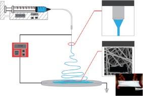
On a bench scale, it is a simple, inexpensive process. To generate nanofibers by electrospinning, an electric potential is applied between a capillary containing a polymer solution or melt and a grounded collector (Figure 1.1). The applied electric field leads to free charge accumulation at the liquid-air interface and electrostatic stress. When the electrostatic stress overcomes surface tension, the free surface deforms into a “Taylor cone.” Balancing the applied flow rate and voltage results in a continuous fluid jet from the tip of the cone. As the jet travels to the collector, it typically undergoes nonaxisymmetric instabilities such as bending and branching leading to extreme stretching. As the fluid jet is stretched, the solvent rapidly evaporates to form the polymer fibers that are deposited onto a grounded target (Reneker and Chun 1996; Helgeson et al. 2008; Rutledge and Fridrikh 2007; Thompson et al. 2007; Teo and Ramakrishna 2006; Li and Xia 2004). As a complex electrohydrodynamic process, the final fiber and mat/membrane properties depend on process parameters by process parameters, setup parameters, and solution properties.
Applications of Polymer Nanofibers, First Edition. Edited by Anthony L. Andrady and Saad A. Khan. © 2022 John Wiley & Sons, Inc. Published 2022 by John Wiley & Sons, Inc.
Process parameters
– Flow rate
– Electric field strength
– Applied voltage
– Tip to collector distance
Solution parameters
– Concentration
– Solution rheology
– Conductivity
– Surface tension
Set up parameters
– Polarity
– Collector
– Electrodes
– Temperature
– Humidity
– Gaseous environment
Figure 1.1 Schematic of conventional electrospinning setup and overview of process, setup, and solution parameters that affect fiber and mat properties. Source: Photograph of mat reprinted from Dror et al. (2008). Copyright (2008). American Chemical Society.
1.2 Effect of Process Parameters
Electrospun fibers from 30 nm to 10 μm in diameter have been reported (Greiner and Wendorff 2007). Despite its widespread use, electrospinning of new materials is typically done ad hoc varying polymer concentration and process variables. Although the nanofiber properties, namely fiber diameter, could be ideally controlled by varying the process parameters, precise control over the fiber diameter remains a technical bottleneck. The effect of process variables on fiber characteristics has been widely examined theoretically and experimentally.
1.2.1 Theoretical Analysis
To avoid the cost and time of experimental trial and error, modeling and theoretical analysis have been applied to predict how process parameters affect fiber diameter. Reneker and coworkers have developed a theoretical model based on simulating jet flow as bead-springs. Their model describes the entire electrospinning process and accounts for solution viscoelasticity, electric forces, solvent evaporation and solidification, surface tension, and jet–jet interactions. Performing sensitivity analysis of 13 model input parameters, they determined that initial jet radius, tip-to-collector distance, volumetric charge density, and solution rheology, i.e. relaxation time and elongational viscosity, had strong effect on final fiber size. Initial polymer concentration, perturbation frequency, solvent vapor pressure, solution density, and electric potential had a moderate effect, whereas vapor diffusivity, relative humidity, and surface tension had minor effects on fiber diameter (Thompson et al. 2007).
Using a simple analytical model focusing on the whipping of the jet treats the jet as a slender viscous object. Rutledge and coworkers assume that the final fiber
diameter is dictated by an equilibrium between Coulombic charge repulsion on the surface of the jet and the surface tension of the liquid jet. The model predicts that terminal jet radius (rj)
where Q is the volumetric flow rate, I is the electric current, γ is the surface tension, is the dielectric constant of the outside medium (typically air), and χ is the dimensionless wavelength of the instability of the normal displacement. The fiber diameter (d) is related to the terminal jet radius and the polymer concentration, c. When compared to experimental results, the model accurately predicted the diameter of polyethylene oxide (PEO) fibers (within 10%) and polyacrylonitrile fibers (within 20%). The theory overpredicted stretching for polycaprolactone fibers, which had relatively low conductivity and high solvent volatility (Fridrikh et al. 2003).
Recently, Stepanyan and coworkers developed an electrohydrodynamic model of the jet elongation in which kinetics of elongation and evaporation govern the nanofiber diameter. Using the timescale of elongation to nondimensionalize the force balance, the timescale of solvent evaporation, and concentration-dependent material functions (e.g. relaxation time), they predict the scaling relationship for the final fiber radius (rf ) is
where k is the solvent evaporation rate, ρs is the solution density, ηo is the solution viscosity, Q is the volumetric flow rate, and I is the electric current. The result for Eq. (1.2) reduces to Eq. (1.1) in the limit of very slow evaporation. The viscosity dependence, ηo1/3, and (Q/I)2/3 agree with experimental results. Using polyvinylpyrrolidone (PVP) in various alcohol solutions as well as polyamide/polyacrylonitrile in dimethylformamide (DMF) solutions, the fiber diameter was experimentally observed to scale with the evaporation rate, k, to the 1/3 power (Stepanyan et al. 2014, 2016).
The current in electrospinning (I) and the volumetric charge density (Q/I) is commonly used in modeling and theoretical approaches. Experimental investigations by Yarin and coworkers determined that
hM M ~ 40 05
where V is applied voltage, Q is flow rate, C polymer concentration, M molecular weight, and H tip to collector distance. Using PEO/water/ethanol mixtures, the solvent properties also slightly affect the current and volumetric charge density. From this work, it is evident that the fiber size is affected by applied electric field strength (applied voltage and time to collector distance), flow rate, and polymer solution (Thompson et al. 2007). Thus, these predictions for fiber size rely on several model parameters that cannot be easily related to measurable variables.
In another work by Rutledge and coworkers, they experimentally determined that the total current in electrospinning, given by IVQK ~ .. 0504 (1.6)
varies electric field (E), volumetric flow rate (Q), and solution conductivity (K). In electrospray, the measured current scales linearly with Q. The authors attributed the observed Q0.5 dependence on combined jet and spray arising from secondary jetting. Secondary jetting was considered a mechanism for dynamic removal of charge from the surface of the jet which affects final fiber diameter and reducing jet stretching due to surface charge repulsion. The secondary jetting can be minimized by reducing the volumetric flow rate or solution conductivity (Bhattacharjee et al. 2010).
Alternative scaling analyses based on the spinning solution properties and electrospinning operating conditions alone have been developed. Based on electrohydrodynamic theory, the Taylor–Melcher slender body theory relates jet kinematics to measurable fluid properties and process variables. Helgeson et al. validated the electrohydrodynamic model with measurements of the jet radius and velocity via in situ high-speed photography and velocimetry in the straight portion of viscoelastic electrospinning jet and PEO/NaCl as a model system. Dimensional analysis of the validated model involves two important quantities the electroviscous number characterizing the electromechanical stress relative to shear stress and the Ohnesorge number (Oh). The relationship for the final fiber diameter was determined to be
where wp is the mass fraction of polymer in solution, ρ is solution density, γ is surface tension, η0 is the zero shear viscosity, Q is the volumetric flow rate, e, is the extensional viscosity, ε is the dielectric constant of the fluid, is the dielectric constant of the surrounding medium (typically atmosphere), and E0 is the strength of the applied electric field. This analysis explicitly contains the extensional viscosity of the fluid known to control fiber formation. The extensional viscosity can be estimated as 3η0 for a Newtonian fluid. This approach assumes the final fiber is
directly proportional to jet radius in the straight portion of the jet and the actual relationship may be system-dependent, i.e. influenced by solution conductivity and mechanics of the bending instability (Helgeson et al. 2008). The predictions agree with experimental observations over a broad range of polymer concentrations and voltages. Upon addition of a significant amount of NaCl, the trends are consistent, but the scaling factor changes and may be attributed to the differences in the bending instability.
Recently, using a force balance on a bent jet considering electric field and surface charge for a Newtonian fluid, Gadkari predicted the final fiber diameter (df ) scales as
where ηo is viscosity, K is conductivity, Q is flow rate, L is tip to collector distance, and V is applied voltage. When compared to experimental results, the scaling prediction qualitatively matches the observed trend for viscosity, flow rate, and applied voltage. The model overpredicts the dependence on volumetric flow rate (0.5 dependence predicted, whereas a 0.3 dependence has been observed experimentally). Experimental values for the scaling relationships for ΔV, L, and K were not available (Gadkari 2014).
1.2.2 Experimental Results
Collectively, theoretical considerations indicate that fiber size is affected by applied electric field strength (applied voltage and time to collector distance), volumetric flow rate, and polymer solution (viscosity and conductivity). However, experimental results have been system-dependent. For example, experiments increasing the voltage has been observed to decrease fiber diameter for many systems such as polyacrylonitrile/DMF and aqueous polyvinyl alcohol due to greater stretching and a stronger electric field. (Andrady 2008). For polyacrylonitrile in DMF, fiber diameter was reduced from ~95 to 50 nm by increasing the voltage from 5 to 25 kV. Conversely, fiber size has increased with increasing voltage. For example, the polystyrene (PS) fibers increased in diameter from 0.31 to 1.72 μm when the applied voltage increased from 5 to 25 kV. The discrepancy in experimental observations indicates that the effect of voltage on fiber size needs to be considered with other process parameters, especially the feed rate and tip-tocollector distance. Notably, at higher applied voltages, there is a greater tendency for bead formation. The bead density increased with increasing voltage and the shape of the beads transitioned from spindle-like to spherical-like indicating instability of the jet (Ramakrishna 2005).
Tip-to-collector distance influences the time of travel, amount of drying, and electric field strength (depending on the applied voltage) and thus the resulting fiber diameter and morphology. Practically, the distance must be large enough to prevent corona discharge. Generally, increasing the tip-to-collector distance with other parameters kept constant reduces fiber diameter. For example, electrospinning polystyrene in chloroform, the fiber diameter decreased from 1 to 0.66 μm by increasing the distance from 5 to 25 cm due to increased time of travel and stretching. Conversely, increasing the distance has also been observed to increase fiber diameter due to the reduced electric field strength. Decreasing the tip-to-collector distance and resulting time of travel and amount of drying can lead to deposition of “wet” fibers that fuse on the collector. While higher electric field strengths can be achieved at shorter distances, it can often result in the formation of beads or an unstable Taylor cone if the distance is not sufficient for development of the whipping instability (Andrady 2008; Ramakrishna 2005).
Continuous nanofibers of uniform diameter are achieved when the feed rate matches the rate of at which solution is removed from the tip. At lower feed rates, fibers may form intermittently. Higher feed rates increase the tendency to form beads. Given sufficient applied voltage, the average fiber diameter increases with feed rate. Increasing the feed rate can also result in fused fibers. With larger volume of solution drawn from the needle top, the solvent may not completely evaporate. The residual solvent may cause the fibers to fuse together when deposited (Andrady 2008; Ramakrishna 2005).
Overall, the experimental results generally agree with the scaling analysis, i.e. the final fiber diameter is directly proportional to volumetric flow rate as well as polymer concentration/viscosity. The electric field strength, dictated by the applied voltage and tip to collector distance, also affects fiber diameter. However, various effects have been observed (e.g. increasing the applied voltage may increase, decrease, or have no effect on the fiber diameter depending on the system) due to the complexity of the process. Some authors have performed systematic experiments varying process parameters and used regression analysis (Cui et al. 2007) or neural network models (Sarkar et al. 2009) to establish quantitative relationships. However, these analyses are system-dependent. There are no methods to date to predict the fiber size based on solution properties and process parameters (Helgeson et al. 2008; Thompson et al. 2007).
1.3 Effect of Setup Parameters
The effect of process parameters (e.g. flow rate, tip-to-collector distance, applied voltage) has been widely studied with conflicting experimental results. An alternative approach to tuning nanofiber and membrane properties has been adjusting parameters of the electrospinning setup.
Ambient conditions (temperature and humidity) affect the electrospinning process and fiber characteristics. The temperature of the spinning solution affects the evaporation rate and the viscosity. At higher temperatures, lower viscosities lead to increased stretching force and result in smaller fibers. Humidity affects solvent evaporation which can affect the resulting fiber characteristics. Using PEO in water as a model system, a twofold monotonic decrease in fiber size was observed with increasing relative humidity. At low humidity, solvent evaporation may be faster than removal of the solution away from the tip of the needle and can lead to needle clogging, especially with volatile solvents. Leveraging humidity to create porous fibers is further discussed in Section 1.6.2. Although, the relative humidity cannot always be readily controlled (Cai and Gevelber 2013), monitoring the ambient temperature and humidity during electrospinning is of practical importance.
Generally, electrospinning is performed in air. Controlling the gaseous environment can be advantageous for affecting fiber diameter. To slow the rate of drying, a gas-jacketed capillary tip can be used to surround the jet with nitrogen saturated with spinning solvent. With slower solvent evaporation, stable Taylor cones could be achieved by electrospinning poly-l-lactic acid in dichloromethane (high volatility). Notably, the flow rate of gas affected the rate of electrospinning. Accelerating the rate of evaporation using an external heat source has also been reported to improve the mat quality of hyaluronic acid fibers spun from water. The improved fiber quality was attributed to increased stretching, enhanced solvent evaporation, and a threefold reduction in viscosity due to the flow of hot air (~60 °C). The composition of the gaseous environment is also an important consideration; it affects leakage of the surface charge on the jet to the surrounding environment and ultimately the fiber size. For example, when using Freon-12 as the electrospinning environment, the fiber diameter was twofold larger than air at the same conditions. This result was attributed to the higher breakdown voltage of Freon-12 compared to air. With a higher breakdown voltage, the fiber retained its electric charge for a longer period of time which would increase the jet velocity and ultimately result in a larger fibers (Ramakrishna 2005; Baumgarten 1971).
Polarity of the applied electric field also affects fiber quality and size. For nylon6 in formic acid, the average fiber diameter was approximately twofold smaller when the capillary was charged with a negative polarity compared to when a positive polarity at the same conditions. Further, the area over which the fibers deposited was smaller in the case of a positive polarity. The difference in fiber quality and size was attributed to increased charge density in the case of negative polarity (Andrady 2008).
Generally, DC voltage is used in electrospinning. The use of alternating current (AC) potential has also been reported. Since the charging of the solution is very rapid, jet initiation occurs before the voltage alternates. The jet contains positive
and negative charged which reduces the repulsive forces and bending instability in the jet. Therefore, using AC the fibers are larger when compared to DC at the same voltage. In AC, there is reduced accumulation of like charges on the deposited fiber. Therefore, thicker layers of electrospun fibers can be achieved, especially when using an insulating collector (Ramakrishna 2005).
Notably, using sharp, pointed needles, i.e. capillary tips results in more efficient charging of the solution. The tip diameter is also an important consideration. Practically, the tip diameter selection is important in avoiding needle clogging due to solvent evaporation. Smaller internal diameters have been observed to reduce beading and reduce the diameter of the fibers (in some cases). As the internal diameter decreases, the surface tension increases and a greater electrostatic force is required for jet initiation leading to smaller fibers. Therefore, the smallest tip that facilitates extrusion of the solution is generally selected. Generally, electrospinning is performed with 16G–27G needles (Andrady 2008; Ramakrishna 2005).
In more complex setups, additional electrodes can be added to tune fiber deposition (Teo and Ramakrishna 2006; Teo et al. 2011). These auxiliary electrodes can be base electrodes, steering electrodes, focusing electrodes, and guiding electrodes (Figure 1.2). The base electrode is usually a conductive plate placed parallel to the collector at the needle tip to improve the uniformity of the electric field and minimize the effect of surrounding objects on the electric field. Since the base electrode increases the stability of the jet, fibers with smaller diameters have been observed. The base electrode should be level with the needle top. Notably, using a base electrode, a higher applied voltage is required to initiate spinning (Teo and Ramakrishna 2006; Teo et al. 2011). Focusing electrodes are used to damp the whipping of the electrostatic jet to achieve more localized deposition. The
Base electrode
Focusing electrodes
Steering electrodes
Collector
Guiding/auxillary electrode
Figure 1.2 Schematic of various electrodes used to control the electrospinning process. Source: Adapted from Teo et al. (2011).
1.3 Effectof SetupParameters 9
electrodes are ring-shaped, cylinder, or conical and placed close to the needle tip. Multiple focusing electrodes can be used to reduce the spread of the fiber deposition. Electrodes with 400 μm diameter holes resulted in ~200 μm diameter nanofiber patches of randomly oriented nanofibers (Teo and Ramakrishna 2006; Teo et al. 2011). Steering electrodes are used to align the electric field in the vicinity of the collector. For example, a pair of parallel electrodes placed near the collector can be used to achieve uniaxially aligned nanofibers. Multiple pairs of steering electrodes are necessary to achieve more complex patterns (Teo and Ramakrishna 2006; Teo et al. 2011).
The collector influences the electric field and is also an important factor in the electrospinning process (Teo and Ramakrishna 2006; Andrady 2008; Ramakrishna 2005; Teo et al. 2011). The simplest collector is a stationary metal plate placed at a fixed distance from the tip. The fibers generally collect as a symmetric circular batch of nanofibers on the plate. Since the plate is grounded, the residual charges on the deposited fibers are dissipated and the mat has high areal density. Moving the collector surface during processing provides some control in the areal density (Andrady 2008). Collectors with grids or charged needles can be used to create patterned nanofiber membranes which consist of regions of highand low-fiber density. Low-fiber density occurs in regions where the collector is insulated. Another common collector is a rotating metal drum/mandrel. The rotating surface leads to an even deposition of fibers and a uniform nanofiber mat. The rotating drum can further stretch the fiber leading to reduced diameters as well as introduce alignment of nanofibers. When using high boiling point solvents, e.g. DMF, a rotating collector can provide a longer time for the solvent to evaporate to prevent fiber fusing. Combining electrospinning and mechanical drawing by collecting on a rotating mandrel can affect fiber size. For example, the diameter of PEO fibers spun from chloroform could be reduced from ~1600 to 600 nm by increasing the velocity of the rotating drum (Ogata et al. 2007). Rotating mandrels are also often used to make tubular constructs for potential application as vascular grafts. For tubular constructs, the wall thickness could be controlled linearly with electrospinning time (Teo and Ramakrishna 2006; Andrady 2008; Ramakrishna 2005; Teo et al. 2011).
The material of the collector is also an important consideration that affects the packing density. When nonconductive materials are used as the collector, charge accumulates, and fewer fibers are deposited resulting in lower-packing densities when compared to fibers collected on conductive surfaces. Even when using conductive collectors, nonconductive behavior can be observed as the fibers (insulating) collect. Sensitivity analysis indicates that the dielectric properties and surface area of the collector are dominant variables that influence fiber diameter and fiber spacing (porosity). Using an auxiliary electrode supplied with AC voltage minimizes the effect of the material on the collector because it reduces the residual
change on the deposited fibers. Collecting in a liquid has also been reported and significantly affects the fiber morphology. The choice of liquid can affect the surface characteristics of the fiber (Ramakrishna 2005).
The porosity of the collector also effects fiber deposition. Fibers collected on metal meshes had lower-packing densities than smooth surfaces. This effect has been attributed to increased evaporation rate when using a porous collector. As the fibers dry faster, the residual charges persist and repel subsequent fibers. Notably, the topography of the deposited fiber mat will follow the texture of the collector (Ramakrishna 2005). Deposition of two-dimensional patterned structures or three-dimensional structures has also been observed. Honeycomb and dimpled structures have been observed using insulating collectors. Twodimensional and three-dimensional patterning is attributed to charge repulsion of deposited fibers. The fibers of the three-dimensional structures are loosely packed and easily compressed. The conditions to form such three-dimensional structures are not well understood (Teo et al. 2011).
Controlling fiber deposition to achieve fiber patterning can be achieved using gap electrodes or open frame collectors. The two parallel electrodes cause the electrostatic field lines in their vicinity to align perpendicular to the edges of the electrodes. The jet aligns with the field lines and deposits uniaxially aligned nanofibers. Charge repulsion of the deposited fibers limits collection of aligned fibers to ~minutes so that samples of thick aligned fibers are difficult to achieve. Arrays of multiple electrodes have been used to achieve more complex patterns, e.g. orthogonal fibers (Teo and Ramakrishna 2006; Andrady 2008; Ramakrishna 2005; Teo et al. 2011).
Alternatively, fibers can be aligned by collecting on a rotating mandrel. The fibers align along the circumference of the mandrel. Typically, high rates of rotation ~1000 rpm are used. To achieve alignment, the rotation of the mandrel must be faster than fiber deposition so that the fibers are taken up on the surface of the mandrel and wound rather than randomly deposited. By replacing a solid mandrel with a wire drum, alignment can be achieved at much lower rates of rotation ~1 rpm. In the case of a wire drum, the fibers are thought to align due to the electric field profile created by the parallel wires. Use of a thin disk with a sharp edge as a collector provides more control of the electrostatic field to align fibers. The electrostatic field lines concentrate toward the knife-edge and the jet tends to follow the direction of the electric field. As the disk rotates (~1000 rpm), the fibers wind continuously along the knife-edge with a pitch of 1–2 μm (Ramakrishna 2005). To improve the alignment, the fibers must be collected before the onset of the whipping instability. Auxiliary electrodes can be used to suppress the whipping instability (Carnell et al. 2008). Alternatively, using solvents with low dielectric constants and high purity can suppress the whipping instability (Ogata et al. 2007). Practically, the highly aligned fibers are achieved for a short period of
time ~ minutes after which alignment decreases, which may be attributed to fiber repulsion due to charge accumulation. Therefore, for complex patterns, mechanical drawing techniques that avoid the electric field and whipping stability are preferable (Nain and Wang 2013).
Nanofiber yarns have also been of interest. To produce yarns, electrospun nanofibers can be deposited on water. As the nanofibers are lifted off the water, the surface of tension bundles the fibers into a yarn. Collecting on water flowing in the form of a vortex is a means to achieving continuous yarn production. The disadvantage of this approach is that the yarn must then be dried. Self-bundling nanofibers have been achieved using AC power. The jet splits and contains both negative and positive segments which bundle together midflight. Twisting the fibers can improve yarn strength. Such twisting can be achieved by collecting on two parallel ring electrodes and rotating one of the rings. Although simple, the length of the yarn is limited using this approach (Abbasipour and Khajavi 2013).
1.4 Effect of Solution Parameters
1.4.1 Polymer Solution Properties (Molecular Weight, Concentration, Viscosity, and Elasticity)
The effect of polymer solution properties is generally more significant than process and setup parameters on electrospinning and the resultant fibers. The solution properties, namely viscosity and viscoelasticity, surface tension, and conductivity are affected by the polymer, solvent(s), and additives (e.g. salts, surfactants).
Although the electrospinning process is relatively easy to implement on a lab scale, many polymer solutions do not form uniform fibers. Issues electrospinning uniform fibers arise when the polymer solution is too dilute and is limited by polymer solubility or when the polymer chains are short or rigid. Electrospinning new materials is typically done ad hoc varying solution properties and process variables; there are no generalizable approaches to predict if a polymer/solvent system will form nanofibers when electrospun. Significant efforts have yielded useful semiempirical approaches for predicting electrospinnability, i.e. production uniform fibers.
It is commonly observed that viscosity influences electrospinning and resulting fiber properties. The viscosity is affected by the molecular weight of the polymer, polymer concentration, and solvent quality. Generally, the higher the molecular weight, the higher the viscosity of the polymer solution. Increasing the polymer concentration also increases the viscosity of the solution. A frequent observation has been that at low viscosities/polymer concentrations, the electrospinning jet breaks up into droplets, rather than stretching to form a fiber. With increasing
Figure 1.3 Specific viscosity as a function of polymer concentration to determine entanglement concentration for PEO of various molecular weights. Scanning electron microscopy (SEM) (PEO 600 kDa) showing the transition from beaded fibers to uniforms as the polymer concentration increases above the entanglement concentration. For neutral polymers in a good solvent, e.g. aqueous PEO, concentrations above ~2.5× the entanglement concentration form uniform fibers. Source: Image of beaded fibers is reprinted from Fong et al. (1999). Copyright (1999), with permission from Elsevier.
concentration, there is a transition to beaded fibers and a second transition to uniform fibers (Figure 1.3). The ability to form uniform fibers has been frequently attributed to polymer entanglement (Andrady 2008; Ramakrishna 2005; Li and Wang 2013).
To quantify the degree of entanglement required to achieve uniform fibers, semiempirical relationships have been used (Shenoy et al. 2005; McKee et al. 2004, 2006). The entanglement concentration can be determined by measuring the viscosity (zero-shear) as a function of polymer concentration and examining the scaling relationship between the specific viscosity and concentration. Note that the specific viscosity (ηsp) accounts for the viscosity of the solvent sp s s 0 (1.9)
where η0 is the zero-shear viscosity of the polymer solution and ηs is the viscosity of the solvent. Upon the onset of polymer entanglement, there is a sharp increase in the scaling relationship based on the theory for semidilute solutions, below the entanglement concentration ηsp α [C]1.25 and above the entanglement concentration ηsp α [C]4.8. For linear, neutral polymers in a good solvent, the transition from beaded fibers to uniform fibers generally occurs at a polymer concentration ~2–2.5× the entanglement concentration (Figure 1.3). This approach has worked well for a number of polymer systems, e.g. polyvinyl alcohol (aqueous), PEO (aqueous), polystyrene in tetrahydrofuran, poly(d-lactic acid) in DMF, and poly(llactic acid) in dichloromethane (Shenoy et al. 2005; McKee et al. 2004). Analogous
approaches have been developed for polyelectrolyte solutions. Polyelectrolytes transition from droplets to fibers at ~8 × Ce. The viscosity scaling relationships for polyelectrolytes to determine the entanglement concentration are an increase in the scaling relationship from ηsp α [C]0.5 to ηsp α [C]1.5 (McKee et al. 2006).
The entanglement concentration can also be used to predict nanofiber diameter based on polymer concentration. A master curve for fiber diameter (df ) as a function of concentration ϕ can be constructed as follows:
where df,e is the diameter of the fibers electrospun at the entanglement concentration ϕe. This result agrees well with the theoretical scaling of 2.3 (Wang et al. 2016).
Long and coworkers showed comparable results with multiple polymers including linear, randomly branched, highly branched, and star polymers (McKee et al. 2004). This approach, which considers polymer concentration, viscosity, and polymer molecular weight (because the entanglement concentration decreases as polymer molecular weight increases), is convenient (Andrady 2008). Due to the high deformation rates, the entangled polymer solutions behave like elastic swollen gels. The rapid stretching of the gel has recently been considered the main mechanism of fiber formation. These results imply that the elasticity of the entangled polymer solution rather than the viscosity influences the final fiber diameter (Wang et al. 2016).
Rutledge and coworkers attribute ability to form uniform fibers to elasticity of the polymer solution noting that the presence of entanglements is a sufficient but not necessary condition for the fluid polymer to demonstrate strong elastic properties. A lack of sufficient elasticity leads to droplets or beaded fibers. To prevent beaded fibers, Rayleigh’s breakup instability must be suppressed. The instability can be slowed down or suppressed by the viscoelasticity of the polymer solution. The timescales for instability and the viscoelasticity can be quantified with the Deborah number (De), i.e. the ratio of the fluid relaxation time and instability growth time. Using blends of poly(ethylene oxide) and poly(ethylene glycol) of various molecular weights to tune the elasticity of the solution, they show a transition from beaded fibers to uniform fibers with increasing Deborah number. At high Deborah number (≫1), the capillary forces that lead to the Rayleigh instability activate the elastic response and delay jet breakup. Deborah numbers above 6 results in uniform fibers because the instability is completely suppressed by elastic forces or arrested at a very early stage of instability growth. There was no observed correlation between the Newtonian viscosity/Ohnesorge number of the fluid and the fiber morphology indicating the elasticity measured by relaxation time is critical for governing the fiber morphology (Yu et al. 2006). The elastic
properties were measured using a capillary breakup extensional rheometer, whereas measuring the entanglement concentration is commonly done with a dynamic shear rheometer. Thus, entanglement concentrations are a popular practical approach.
1.4.2 Solvent Selection
Solvent selection is also an important consideration. Currently, solvent selection is based on trial and error. Further, the solvent characteristics cannot be independently varied to tune desired fiber properties. The key properties of commonly used electrospinning solvents are provided in Table 1.1. Practically, solvent volatility affecting evaporation rate is an important consideration. If solvent remains when the fiber is deposited, the wet fibers can fuse together or result in a ribbonlike fiber. To avoid such issues, more volatile solvents can be used. However, highly volatile solvents can result in needle clogging. Further, the average fiber diameter of polystyrene fibers has been observed to be inversely proportional to solvent boiling point. Fibers between ~5 and 0.2 μm were achieved by varying the boiling point of the solvent (Wannatong et al. 2004).
In addition to the rate of evaporation, the solvent affects the conformation of the dissolved polymer chains as well as the solution conductivity, surface tension, and viscosity. Generally, good solvents that yield open conformations of polymer chains (to promote entanglement) and sufficient polymer solubility to achieve high solids contents are preferred for electrospinning (Andrady 2008). Luo and coworkers considered 49 solvents for electrospinning polycaprolactone. Solubility
Table 1.1 Key solvent properties for common electrospinning solvents.