E-Paper Displays Bo Ru Yang
Visit to download the full and correct content document: https://ebookmass.com/product/e-paper-displays-bo-ru-yang/
More products digital (pdf, epub, mobi) instant download maybe you interests ...
The
Facial Displays of Leaders Carl Senior
https://ebookmass.com/product/the-facial-displays-of-leaderscarl-senior/
Comprehensive Geographic Information Systems Bo Huang (Editor)
https://ebookmass.com/product/comprehensive-geographicinformation-systems-bo-huang-editor/
Introduction to Flat Panel Displays 2nd Edition JiunHaw Lee
https://ebookmass.com/product/introduction-to-flat-paneldisplays-2nd-edition-jiun-haw-lee/

CompTIA Linux+ XK0-005 Exam Cram William “Bo” Rothwell
https://ebookmass.com/product/comptia-linux-xk0-005-exam-cramwilliam-bo-rothwell/
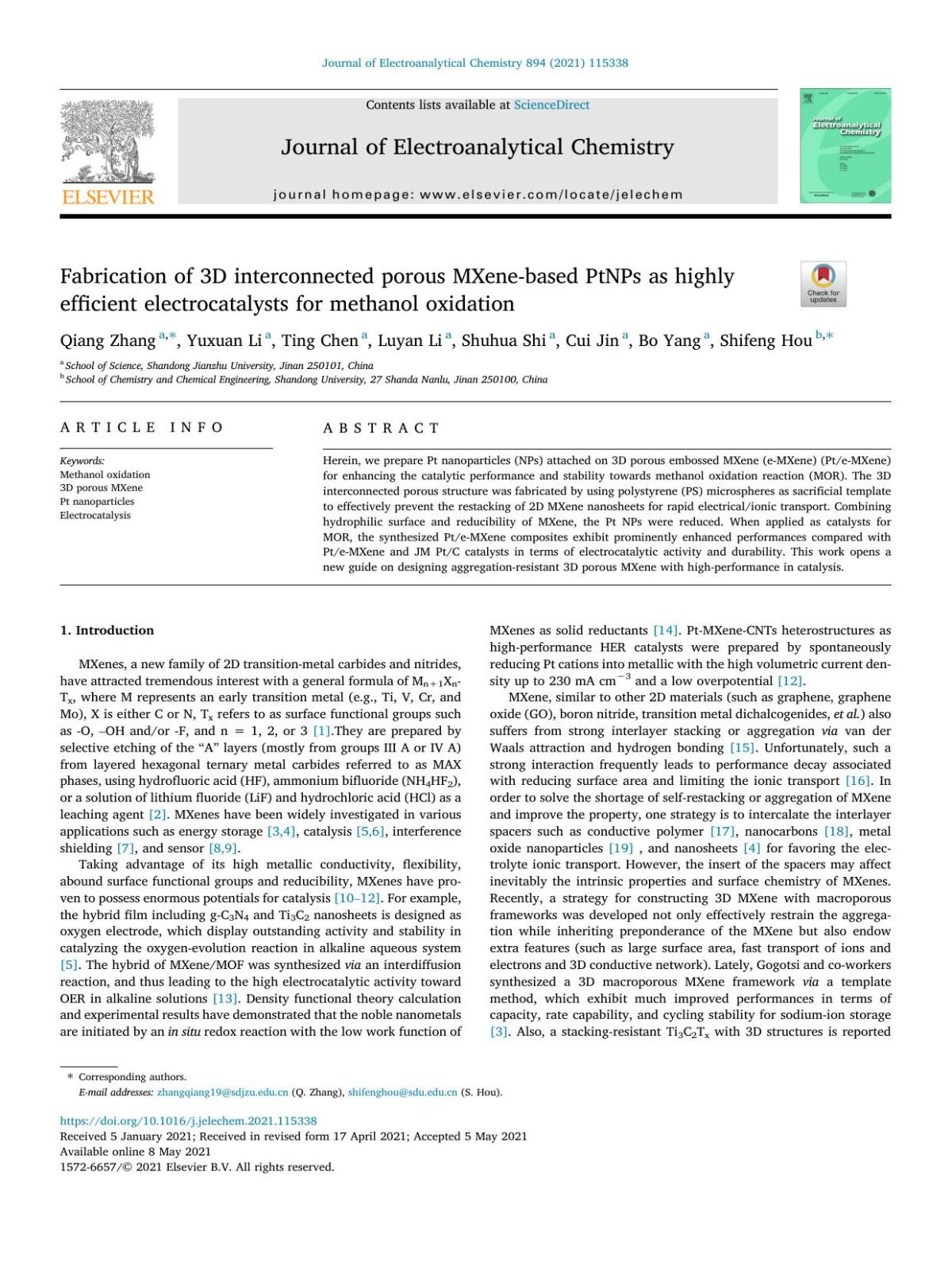
Fabrication of 3D interconnected porous MXene-based PtNPs as highly efficient electrocatalysts for methanol oxidation Qiang Zhang & Yuxuan Li & Ting Chen & Luyan
Li & Shuhua Shi & Cui Jin & Bo Yang & Shifeng Hou
https://ebookmass.com/product/fabrication-of-3d-interconnectedporous-mxene-based-ptnps-as-highly-efficient-electrocatalystsfor-methanol-oxidation-qiang-zhang-yuxuan-li-ting-chen-luyan-lishuhua-shi-cui-jin-bo-yang/

ETABETA - La matematica per tutti - Edizione kmzero - 3 Gianfranco Bo
https://ebookmass.com/product/etabeta-la-matematica-per-tuttiedizione-kmzero-3-gianfranco-bo/
Multimaterial 3D Printing Technology Jiquan Yang
https://ebookmass.com/product/multimaterial-3d-printingtechnology-jiquan-yang/
Advanced Polyimide Materials Shi-Yong Yang
https://ebookmass.com/product/advanced-polyimide-materials-shiyong-yang/

China and Global Governance: A New Leader? 1st Edition Peng Bo
https://ebookmass.com/product/china-and-global-governance-a-newleader-1st-edition-peng-bo/
E-Paper Displays
Wiley– SID Series in Display Technology
Series Editor: Dr. Ian Sage
Advisory Board: Paul Drzaic, Ioannis (John) Kymissis, Ray Ma, Ian Underwood, Michael Wittek, Qun (Frank) Yan
E-Paper Displays
Bo-Ru Yang (Ed.)
Liquid Crystal Displays - Addressing Schemes and Electro-Optical Effects, Third Edition
Ernst Lueder, Peter Knoll, and Seung Hee Lee
Flexible Flat Panel Displays, Second Edition
Darran R. Cairns, Dirk J. Broer, and Gregory P. Crawford
Amorphous Oxide Semiconductors: IGZO and Related Materials for Display and Memory
Hideo Hosono, Hideya Kumomi
Introduction to Flat Panel Displays, Second Edition
Jiun-Haw Lee, I-Chun Cheng, Hong Hua, and Shin-Tson Wu
Flat Panel Display Manufacturing
Jun Souk, Shinji Morozumi, Fang-Chen Luo, and Ion Bita
Physics and Technology of Crystalline Oxide
Semiconductor CAAC-IGZO: Application to Displays
Shunpei Yamazaki, Tetsuo Tsutsui
OLED Displays: Fundamentals and Applications, Second Edition
Takatoshi Tsujimura
Physics and Technology of Crystalline Oxide
Semiconductor CAAC-IGZO: Fundamentals
Noboru Kimizuka, Shunpei Yamazaki
Physics and Technology of Crystalline Oxide
Semiconductor CAAC-IGZO: Application to LSI
Shunpei Yamazaki, Masahiro Fujita
Interactive Displays: Natural Human-Interface Techniques
Achintya K. Bhowmik
Addressing Techniques of Liquid Crystal Displays
Temkar N. Ruckmongathan
Modeling and Optimization of LCD Optical Performance
Dmitry A. Yakovlev, Vladimir G. Chigrinov, and Hoi-Sing Kwok
Fundamentals of Liquid Crystal Devices, Second Edition
Deng-Ke Yang and Shin-Tson Wu
3D Displays
Ernst Lueder
Illumination, Color and Imaging: Evaluation and Optimization of Visual Displays
P. Bodrogi, T. Q. Khan
Liquid Crystal Displays: Fundamental Physics and Technology
Robert H. Chen
Transflective Liquid Crystal Displays
Zhibing Ge and Shin-Tson Wu
LCD Backlights
Shunsuke Kobayashi, Shigeo Mikoshiba, and Sungkyoo Lim (Eds.)
Mobile Displays: Technology and Applications
Achintya K. Bhowmik, Zili Li, and Philip Bos (Eds.)
Photoalignment of Liquid Crystalline Materials: Physics and Applications
Vladimir G. Chigrinov, Vladimir M. Kozenkov, and Hoi-Sing Kwok
Projection Displays, Second Edition
Mathew S. Brennesholtz and Edward H. Stupp
Introduction to Microdisplays
David Armitage, Ian Underwood, and Shin-Tson Wu
Polarization Engineering for LCD Projection
Michael G. Robinson, Jianmin Chen, and Gary D. Sharp
Digital Image Display: Algorithms and Implementation
Gheorghe Berbecel
Color Engineering: Achieving Device Independent Color
Phil Green and Lindsay MacDonald (Eds.)
Display Interfaces: Fundamentals and Standards
Robert L. Myers
Reflective Liquid Crystal Displays
Shin-Tson Wu and Deng-Ke Yang
Display Systems: Design and Applications
Lindsay W. MacDonald and Anthony C. Lowe (Eds.)
E-Paper Displays
Edited by Bo-Ru Yang
State Key Lab of Opto-Electronic Materials & Technologies, Guangdong Province Key Lab of Display Materials and Technologies, School of Electronics and Information Technology, Sun Yat-Sen University, Guangzhou, China
This edition first published 2022 © 2022 John Wiley & Sons Ltd
All rights reserved. No part of this publication may be reproduced, stored in a retrieval system, or transmitted, in any form or by any means, electronic, mechanical, photocopying, recording or otherwise, except as permitted by law. Advice on how to obtain permission to reuse material from this title is available at http://www.wiley.com/go/permissions.
The right of Bo-Ru Yang to be identified as the author of the editorial material in this work has been asserted in accordance with law.
Registered Offices
John Wiley & Sons, Inc., 111 River Street, Hoboken, NJ 07030, USA
John Wiley & Sons Ltd, The Atrium, Southern Gate, Chichester, West Sussex, PO19 8SQ, UK
Editorial Office
The Atrium, Southern Gate, Chichester, West Sussex, PO19 8SQ, UK
For details of our global editorial offices, customer services, and more information about Wiley products visit us at www.wiley.com.
Wiley also publishes its books in a variety of electronic formats and by print-on-demand. Some content that appears in standard print versions of this book may not be available in other formats.
Limit of Liability/Disclaimer of Warranty
In view of ongoing research, equipment modifications, changes in governmental regulations, and the constant flow of information relating to the use of experimental reagents, equipment, and devices, the reader is urged to review and evaluate the information provided in the package insert or instructions for each chemical, piece of equipment, reagent, or device for, among other things, any changes in the instructions or indication of usage and for added warnings and precautions. While the publisher and authors have used their best efforts in preparing this work, they make no representations or warranties with respect to the accuracy or completeness of the contents of this work and specifically disclaim all warranties, including without limitation any implied warranties of merchantability or fitness for a particular purpose. No warranty may be created or extended by sales representatives, written sales materials or promotional statements for this work. The fact that an organization, website, or product is referred to in this work as a citation and/or potential source of further information does not mean that the publisher and authors endorse the information or services the organization, website, or product may provide or recommendations it may make. This work is sold with the understanding that the publisher is not engaged in rendering professional services. The advice and strategies contained herein may not be suitable for your situation. You should consult with a specialist where appropriate. Further, readers should be aware that websites listed in this work may have changed or disappeared between when this work was written and when it is read. Neither the publisher nor authors shall be liable for any loss of profit or any other commercial damages, including but not limited to special, incidental, consequential, or other damages.
Library of Congress Cataloging-in-Publication Data
Names: Yang, Bo-Ru, 1979– editor.
Title: E-paper displays / edited by Bo-Ru Yang, State Key Lab of Opto-Electronic Materials & Technologies, Guangdong Province Key Lab of Display Materials and Technologies, School of Electronics and Information Technology, Sun Yat-Sen University, Guangzhou, China. Description: First edition. | Hoboken, NJ : John Wiley & Sons, 2022. | Series: Wiley SID series in display technology | Includes bibliographical references and index.
Identifiers: LCCN 2021061537 (print) | LCCN 2021061538 (ebook) | ISBN 9781119745587 (hardback) | ISBN 9781119745594 (adobe pdf) | ISBN 9781119745600 (epub)
Subjects: LCSH: Electronic paper.
Classification: LCC TK7882.E44 E24 2022 (print) | LCC TK7882.E44 (ebook) | DDC 004.5/6–dc23/eng/20220207
LC record available at https://lccn.loc.gov/2021061537
LC ebook record available at https://lccn.loc.gov/2021061538
Cover Design: Wiley
Cover Image: © Marko Aliaksandr/Shutterstock.com
Set in 9.5/12.5pt STIXTwoText by Straive, Pondicherry, India
Contents
List of Contributors xi
Series Editor’s Foreword xiii
Editor’s Preface xv
1 The Rise, and Fall, and Rise of Electronic Paper 1
Paul S. Drzaic, Bo-Ru Yang, and Anne Chiang
1.1 Introduction 1
1.2 Why Electronic Paper? 2
1.3 Brightness, Color, and Resolution 2
1.4 Reflectivity and Viewing Angle 4
1.5 Translating Print-on-Paper into Electronic Paper 5
1.5.1 Brightness 5
1.5.2 Grayscale – Analog vs. Digital 6
1.5.3 An Overview of Approaches to Color Electronic Paper 6
1.6 The Allure of Electronic Paper vs. the Practicality of LCDs 10
1.7 The Evolution of Electrophoretic Display-Based Electronic Paper 11
1.7.1 Early History 11
1.8 Initial Wave of Electrophoretic Display Development 12
1.8.1 The Electrophoretic Fluid, Thresholds, and Memory 12
1.8.2 Memory Function, Device Stability, and Control Grids 13
1.8.3 Optics 14
1.8.4 EPD in Decline 16
1.9 The Revival of EPDs 17
1.10 Developing a Commercial Display 18
1.11 Enhancing Brightness and Contrast 19
1.12 Microencapsulation Breakthrough 20
1.13 Image Retention 21
1.14 Active-Matrix Compatibility 23
1.14.1 Reproducible Gray Scale 24
1.14.2 Overcoming “kickback” Phenomena 24
1.14.3 EPD Panel Manufacturing 24
1.15 Electronic Book Products, and E Ink Merger 25
1.16 Summary 26
Acknowledgments 26
References 26
2 Fundamental Mechanisms of Electrophoretic Displays 31 Bo-Ru Yang and Kristiaan Neyts
2.1 General View of Electronic Ink Operation 31
2.2 Charging Mechanism with Inverse Micelle Dynamics 33
2.3 Drift and Diffusion of Charged Inverse Micelles 35
2.4 Motion of Charged Inverse Micelles Under External Field Driving 38
2.5 Stern Layer Formation 41
2.6 Charging Mechanism with Particles and Additives 44
2.7 Observations on a Single Particle 44
2.8 Rheological Effects During Driving 47
2.9 Bistability After Removing External Fields 48
2.10 Full Color E-Paper 49
2.11 Conclusion 50
References 50
3 Driving Waveforms and Image Processing for Electrophoretic Displays 53 Zong Qin and Bo-Ru Yang
Overview 53
3.1 Driving Waveforms of EPDs 53
3.1.1 Fundamental Concepts of Waveforms 53
3.1.2 DC-Balance Waveforms 56
3.1.3 Waveform Design with Temperature Considerations 57
3.1.4 Driving System and Lookup Table 58
3.1.5 Driving Schemes for Color E-Papers 60
3.2 Image Processing 61
3.2.1 Digital Dithering and Halftoning 62
3.2.1.1 Pixel-Wise Method 64
3.2.1.2 Error-Diffusion Method 64
3.2.1.3 DBS Method 66
3.2.2 Image Calibration 67
3.3 Advanced Driving Methods for Future E-Papers 69
3.3.1 Self-Powered EPDs 71
3.3.2 Three-Dimensional Driving 72
References 72
4 Fast-Switching Mode with CLEARInk Structure 75
Robert J. Fleming
4.1 Introduction 75
4.2 CLEARink Display Optics 78
4.3 CLEARink Reflective Color Displays 85
4.4 Electrophoretic Displays with CLEARink Structure 89
4.5 CLEARink Device Architecture 93
4.6 Manufacturing and Supply Chain 96
4.6.1 Status of Technology and Future Projections 96 Acknowledgments 97
References 97
5 Bistable Cholesteric Liquid Crystal Displays – Review and Writing Tablets 99 Clinton Braganza and Mauricio Echeverri
5.1 Introduction 99
5.2 Materials and Optical Properties 99
5.2.1 Optical Properties of Cholesteric Liquid Crystals 100
5.2.1.1 Color from Cholesteric Liquid Crystals 100
5.2.1.2 Optimizing Cholesteric Liquid Crystals for ePaper Applications 101
5.2.1.3 Optical and Mechanical Effects of Polymer Networks 101
5.3 Image Creation Using Cholesteric Liquid Crystals 104
5.3.1 Electrical Addressing 104
5.3.1.1 Driving Schemes 105
5.3.2 Photo Addressing 107
5.3.3 Pressure Addressing 107
5.4 Applications 108
5.4.1 Displays for Reading 108
5.4.2 Rugged Passive Driven Displays 108
5.4.3 Electronic Skins 109
5.5 Writing Tablets 109
5.5.1 Writing Tablet Structure 109
5.5.2 Fabrication of Writing Tablets 110
5.5.3 Polymer Morphology of CHLC Writing Tablets 111
5.5.4 Characteristics of Writing Tablets 114
5.5.4.1 Writing Mechanism 114
5.5.4.2 Electro- Optic Response of Writing Tablets 118
5.5.4.3 Exact Erase 119
5.5.4.4 Writing Reliability 120
5.5.5 Semi-Transparent Writing Tablets 122
5.5.6 Multi- Colored Writing 124
5.5.7 Large Format Writing Surfaces 124
5.5.8 Saving the Written Image 125
5.6 Conclusions 126
References 126
6 The Zenithal Bistable Display: A Grating Aligned Bistable Nematic Liquid Crystal Device 131
Guy P. Bryan-Brown and J. Cliff Jones
6.1 Introduction 131
6.2 Operating Principles and Geometries 132
6.3 Grating Fabrication and Supply Chain 138
6.4 ZBD LCD Manufacturing Processes 141
6.5 Electrical Addressing 144
6.6 Optical Configurations 145
6.7 Novel Arrangements 149
6.8 Conclusions 150
Acknowledgments 151
References 151
7 Reflective LCD with Memory in Pixel Structure 153
Yoko Fukunaga
7.1 Introduction 153
7.2 Memory in Pixel Technology and Its Super Low Power Operation 154
7.3 Sub-Pixel Pattern to Show Gray Scale 157
7.4 Reflective LCD Optical Design 158
7.4.1 Light Scattering Functionality 158
7.4.2 LCD Cell Design 159
7.4.3 Pixel Design for Auxiliary Lighting 160
7.4.4 Super Low Power Driving for Auxiliary Lighting 163
7.5 How to Show a Natural Image 163
7.6 Design Characteristics of Current Market-Available Products and Their Super Low Power Operations 164
7.7 Summary of Power Consumption 167
7.8 Applications 168
7.9 Future Expectations 168 References 169
8 Optically Rewritable Liquid Crystal Display 171
Wanlong Zhang, Abhishek Srivastava, Vladimir Chigrinov, and Hoi-Sing Kwok
8.1 Introduction 171
8.2 Photoalignment Technology 172
8.2.1 Optically Rewritable Liquid Crystal Display 174
8.2.2 Optical Rewriting Speed Optimization 177
8.2.3 Optical Rewriting Time with Different Liquid Crystals 178
8.2.4 Optical Rewriting Time with Application of External Electrical Field 180
8.2.5 Grayscale Optically Rewritable LCD 180
8.2.6 Three-dimensional Optically Rewritable LCD 183
8.2.7 Full-color Optically Rewritable LCD 184
8.3 Flexible Optically Rewritable LCD 186
8.4 Dye-Doped Optically Rewritable LCD 188
8.5 Conclusion 190 References 190
9 Electrowetting Displays 197
Doeke J. Oostra
9.1 Overviews 197
9.2 Introduction 197
9.2.1 Reading or Viewing Experience 198
9.2.2 Full Color 199
9.2.3 Video Content 200
9.2.4 Ultra-Low Power Consumption 200
9.2.5 Fitness for the Application 200
9.2.6 Priced for the Application 200
9.3 The Promise of Electrowetting Displays 200
9.4 History of Electrowetting Display Development 204
9.5 Electrowetting Cells 205
9.6 Capabilities for Black and White 206
9.6.1 Black 207
9.6.2 White 207
9.6.3 Cell Pitch, Pixel Pitch and Effect on Maximum White Level 209
9.7 Capabilities for Video and Color 209
9.7.1 Video 209
9.7.2 Color 209
9.7.3 Parallax 210
9.7.4 Application and Design 211
9.7.5 Pixel Pitch and Driving Mechanism 212
9.7.6 Gray Scales 214
9.8 Driving 215
9.8.1 Power Consumption 215
9.8.2 Driving Voltage 215
9.9 Architectures 216
9.9.1 First Generation 216
9.9.2 Second Generation 216
9.9.3 Two Layers 217
9.10 Manufacturing 217
9.10.1 Preparation Superstrate 217
9.10.2 Preparation Substrate 218
9.10.3 Bipane Manufacturing 219
9.10.4 Test and Measurement 219
9.11 Reliability 220
9.12 Failure Mechanisms 220
9.13 In Conclusion: Electrowetting Displays Have Reached Maturity 221 Acknowledgments 222 References 222
10 Electrochromic Display 225
Norihisa Kobayashi
10.1 Introduction 225
10.2 Structure of Electrochromic Display 226
10.3 EC Materials 228
10.3.1 Inorganic EC Materials 228
10.3.2 Organic Electrochromic Materials 229
10.3.3 Conducting Polymers 234
10.3.4 Electrodeposition (Electroplating) 236
10.4 Summary 239
References 239
11 Phase Change Material Displays 243
Ben Broughton and Peiman Hosseini
11.1 Introduction 243
11.2 Phase Change Materials and Devices 243
11.3 Strong Interference in Ultra-Thin Absorbing Films 244
11.4 Potential for High Brightness, Low Power Color Reflective Displays 245
Contents x
11.5 Solid-State Reflective Displays (SRD®) 248
11.5.1 Microheater Switched PCM Pixels 248
11.5.2 RGB-to-Pale Pixel Color, Controlled by Layer Thickness 251
11.5.3 Phase Change Material Development 252
11.5.4 LTPS Backplane Development 256
11.6 SRD Prototype – Progress and Performance 259
11.6.1 Fully Functioning Display Demonstrators 260
11.6.2 Potential Applications 263
11.7 Other Approaches 263
11.8 Conclusions 265
Acknowledgments 266
References 266
12 Optical Measurements for E-Paper Displays 271
Karlheinz Blankenbach
12.1 Introduction 271
12.2 Fundamentals of Reflection 272
12.3 Reflection Measurements Set-Ups 273
12.4 Display Image Quality Parameters 276
12.4.1 Luminance 277
12.4.2 Contrast Ratio 277
12.4.3 Gray Scale 279
12.4.4 Color 279
12.5 Temporal Parameters 281
12.5.1 Switching Time 281
12.5.2 Bi-stability 282
12.5.3 Lifetime 283
12.5.4 Flexible Displays 283
12.6 Further Topics 283
12.7 Summary 283
Glossary incl. Abbreviations 284
References 284
Index 287
List of Contributors
Karlheinz Blankenbach
Pforzheim University
Display Lab
Pforzheim, Germany
Clinton Braganza Portage Blvd Kent, USA
Ben Broughton Oxford, UK
Guy P. Bryan-Brown
Director of Technology
New Vision Display, Inc. Malvern, UK
Anne Chiang
Chiang Consulting, Cupertino, USA
Vladimir Chigrinov
State Key Laboratory of Advanced Displays and Optoelectronics Technologies
Hong Kong University of Science and Technology
Hong Kong S. A. R., China
Paul S. Drzaic Apple, Inc. CA, USA
Mauricio Echeverri
Kent Displays Inc. Portage Blvd Kent, USA
Robert J. Fleming CTO CLEARink Displays San Jose, CA, USA
Yoko Fukunaga JDI Higashiura Plant Aichi-ken, Japan
Peiman Hosseini Bodle Technologies Oxford, UK
J. Cliff Jones
School of Physics and Astronomy University of Leeds Cheshire, UK
Norihisa Kobayashi
Graduate School of Engineering Chiba University Japan
Hoi-Sing Kwok
State Key Laboratory of Advanced Displays and Optoelectronics Technologies
Hong Kong University of Science and Technology
Hong Kong S. A. R., China
Kristiaan Neyts
Professor and Head of Liquid Crystals and Photonics Group, ELIS Department, Ghent University, Belgium
Doeke J. Oostra Etulipa, a Miortech company The Netherlands
List of Contributors
Zong Qin
School of Electronics and Information Technology
Sun Yat-Sen University
Guangzhou, China
Abhishek Srivastava
State Key Laboratory of Advanced Displays and Optoelectronics Technologies
Hong Kong University of Science and Technology
Hong Kong S. A. R., China
Wanlong Zhang
State Key Laboratory of Advanced Displays and Optoelectronics Technologies
Hong Kong University of Science and Technology
Hong Kong S. A. R., China
Series Editor’s Foreword
Paper is the medium which has dominated the presentation of both the written word and graphics for two thousand years. The happy partnership of paper with printing was first developed in China before being adopted in the Western world in the Middle Ages and it initiated the first information explosion. Perhaps no other invention has had such a fundamental influence on the development of human society and way of life. Printed books and periodicals are attractive, affordable, and so familiar that we can truly pay attention to the contents alone, and overlook the qualities of the physical page. With this cultural and technical background, it is not surprising that printed paper is widely regarded as a reference point for electronic display technologies and since the introduction of the first flat panel displays, achieving paper-like performance has been a common dream and aspiration of engineers. At the same time, users have bemoaned the shortcomings of electronic displays and the poor reading experience offered by early generations of displays. In the present volume, Professor Bo-Ru Yang has brought together an outstanding selection of authors to examine the technologies which aspire to mimic the properties of printed paper. It is fair to say that no electronic display can yet rival all the desirable characteristics of paper, and a basic question which arose at an early point in the planning of the volume, was which technologies or aspects of performance should be included. Professor Yang and his team have taken an inclusive approach. In this book the reader will find accounts of displays which offer different combinations of desirable properties including paper-like appearance under ambient light, long-term image storage with zero or ultra-low power consumption, light weight and flexibility, and the ability to accept user input with the ease of pencil on paper. It follows that a wide range of display technologies are included, with an emphasis on device modes which offer ambient light viewability. Several liquid crystal modes, both with and without polarizer, can provide image storage either intrinsic to the display or in ultra-low power drive electronics. Meanwhile, displays based on electrophoretic or electrowetting effects can offer outstanding optical appearance under a wide range of ambient lighting. Innovative and emerging displays are also considered, with a chapter on phase-change displays offering an early view of the potential of this new development. Of course, physics of operation, the fabrication, engineering and especially the addressing characteristics of each display mode can be very different, and these issues are comprehensively covered, with special attention to those aspects of the devices which are less well covered in earlier sources. Other, user-related properties of the devices—the difficulty of providing high quality reflective colour, and the relation of the display performance to human perception of image quality and metrology are carefully considered. In the 21st century, our priorities regarding electronic displays have changed. Excellent optical performance is today taken for granted while convenience, light weight and long battery life have increasingly driven user approval. Especially, the environmental impact of every activity we undertake, now demands scrutiny. Printed media are major consumers of environmental resources including energy, timber, carbon emissions and chemical residues while electronic devices have the potential to reduce or eliminate these problems—but only if they are responsibly manufactured and accepted by users sufficiently to displace print over a long period of use and wide range of use cases. Paper-like display quality can really make a difference to the world. The present book provides a comprehensive and authoritative overview of the field, authored by leading experts on each aspect of the subject, and I believe it will offer a most valuable source of reference to display professionals and advanced students, for many years to come.
Editor’s Preface
With the advent of the Internet of Things (IoT), devices and objects around us are being equipped with built-in sensors and electronics which allow them to analyse and share information in real time, in the manner we associate with intelligent organisms. It follows that vast numbers of devices will be fitted with displays to present the information. The needs of such autonomous miniature devices mean that displays with low power consumption, excellent sunlight readability, and geometrical conformability which are compatible with low-cost fabrication methods, are becoming critical components in future IoT environments. E-paper displays have the inherent advantages of reflective operation, zero-power bistability, and in many cases they can be fabricated by printing-based processes. Therefore, they are regarded as among the most promising display technologies for these applications. Furthermore, many recent applications, such as fixed and mobile signage for transport, advertising billboards, architectural coatings, wrapped vehicles, e-readers, retail labelling, dynamic artworks, and many others, have started to exploit the unique advantages of E-paper.
Unlike LCD and OLED technologies, E-paper display technologies have not up until now been collectively and comprehensively reviewed, and there has been no published source which can provide scientists, engineers, and users with enough broad, insightful, and up-to-date knowledge to support research and development or product integration in this field. To fill this need, the present book represents the achievement of a three-year collaboration with prestigious scholars, experts, and entrepreneurs in E-paper display fields.
In this book, we have tried to cover as extensive a range of E-paper technologies as possible. Started with the development history of electrophoretic displays, followed by the fundamental mechanisms, physical models, driving waveforms, image processing, and advanced structures of electrophoretic displays, we describe the technological details and review the development progress to show how electrophoretic E-papers become commercially successful. In addition, bistable and reflective LCDs for E-paper applications, including Cholesteric LC, Zenithally Bistable Display (ZBD), Memory in Pixel (MIP), and Optically Rewritable (ORW) LCDs are also introduced. After that, the emergent technologies such as electro-wetting, electro-chromic, and phase change materials for E-paper display applications are reported and summarized. In the last part, the special needs for metrology of E-paper displays are explained. This book covers the broad spectrum of state-of-the-art reflective and bistable E-paper technologies, and we believe it will provide an invaluable handbook and reference for researchers, advanced students, and professionals in this field.
The Rise, and Fall, and Rise of Electronic Paper
Paul S. Drzaic1, Bo-Ru Yang2, and Anne Chiang3
1 Apple, Inc
2 Professor, School of Electronics and Information Technology, State Key Laboratory of Optoelectronic Materials and Technologies, Guangdong Province Key Laboratory of Display Material and Technology, Sun Yat-Sen University, Guangzhou, China
3 Principal, Chiang Consulting, Cupertino, CA
1.1 Introduction
For over a thousand years, before the world of electronics, paper was the dominant medium for people to share written and later printed information. People become familiar with paper at an early age, and there is an enormous worldwide infrastructure for the production and distribution of printed material. Despite this huge built-in advantage, paper and print now fall short in providing for many demands of modern life. The past few decades have seen the emergence of electronic networks that transmit vast amounts of information, on-demand, for use in various ways. Electronic displays are a necessary part of this infrastructure, converting bits to photons and serving as the final stage of transmitting information to people.
Over the years, several electronic display technologies have waxed and waned; cathode ray tubes, plasma displays, and super twisted nematic (STN) displays come to mind. A few technologies are dominant; backlit active-matrix liquid crystal displays, active matrix organic light-emitting diode (OLED) displays, and inexpensive, passively addressed liquid crystal displays. Along the way, tens of different types of display technologies have been invented and explored, but ultimately have failed to catch on. A few displays have found a home in niche products and promise greater future application. Reflective displays, particularly electronic paper, are examples that have managed to find a place in the display ecosystem, with unique applications best served by these technologies.
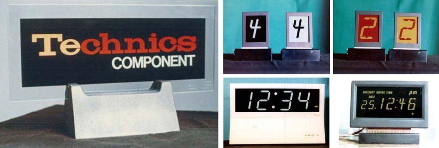
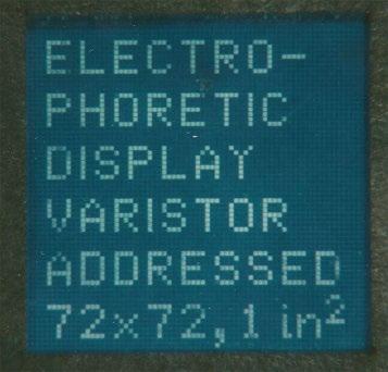
This book aims to update on some of the most exciting new areas in electronic paper technology. This introductory chapter focuses primarily on electrophoretic displays (EPDs) and how they became synonymous with electronic paper. The story starts in the early 1970’s, with the proposal and first demonstration of the electrophoretic movement of charged particles to make an optical effect. After intense effort, the technology was mostly abandoned, only to be resurrected by a start-up company, E Ink. Several key, and rather improbable inventions had to be made to develop a technology competitive to the dominant liquid crystal technology. Finally, the right application and ecosystem, the Amazon Kindle electronic book, was necessary to cement commercial success.
The field of reflective displays is very rich. The many other chapters in this book and recent reviews [1, 2] provide a wealth of resources for understanding the many technologies that have been developed in the quest to achieve a paper-like display. In this chapter, we will examine the following:
● A description of print-on-paper and how the optics of real paper compare with potential electronic paper competitors.
● A hierarchical summary of the different technical approaches for reflective displays.
● A detailed look at the historical development of EPDs, starting with the invention of the technology and ending with the introduction of the Amazon Kindle. Looking at the various developments in the context of its times, the EPD story offers some lessons in what it takes for a technology to transition from the laboratory to commercial success.
1.2 Why Electronic Paper?
Electronic paper has undoubtedly caught the imagination of the world. A Google search for electronic paper in September 2021 returns over 12 billion hits. This interest reflects people’s love affair with paper as a medium for transmitting information. Yet, it is easy to recognise that printing ink onto dead trees is not easily compatible with today’s networked world. What are the attributes of print-on-paper that make it so important?
● Paper is a reflective medium that automatically adapts to changing lighting
● Unlike most emissive displays, paper can be easily read in bright sunlight.
● The appearance of paper is relatively constant over different viewing angles, without significant shifts in luminance or color.
● Paper can be lightweight and flexible. The user can easily annotate it. with a pen or pencil.
● Paper is inexpensive
● Paper can be archived.
Nevertheless, physical paper cannot be instantly updated with information from electronic networks or easily serve as an interface with electronic devices. Today’s backlit LCDs and OLED displays are ubiquitous as a means of transmitting information, but with the limitations that emissive displays possess, including eyestrain and low visibility in sunlight. Electronic paper can combine the power of electronic devices and networks with all the attributes of paper.
So what strategies can be taken to enable electronic paper? It is instructive to understand the composition and design of print-on-paper and see how many of these properties can be converted to something under electronic control to compete with printed media.
1.3 Brightness, Color, and Resolution
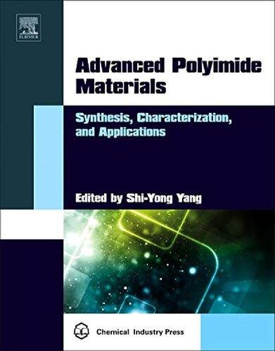
Conventional, non-electronic paper consists of a mat of tightly pressed fibers, most commonly derived from parchment or wood pulp. The combination of fibers and embedded air pockets scatter light and provide the reflective characteristics of paper. Historically, additives to the paper pulp during fabrication have also provided glossiness, color, aid in manufacture, or other desirable characteristics (Figure 1.1).
Compared to a white optical standard, the perceived reflectivity of paper often ranges from 50–80%, but can be even higher. The whiteness or brightness of paper depends on several factors, including the density of fibers, the paper thickness, the presence of additives such as titanium dioxide, clays, or fluorescent agents, and whether the viewing surface is made glossy through calendaring and coatings. The color of light reflected from white paper may differ somewhat from a perfect reflector due to the fluorescing whiteners’ presence, or some underlying color absorbance from the paper. The human eye readily accommodates for these changes, though, so the perception of consistent color and lightness of a page relative to its surroundings is easily achieved (Figure 1.2).
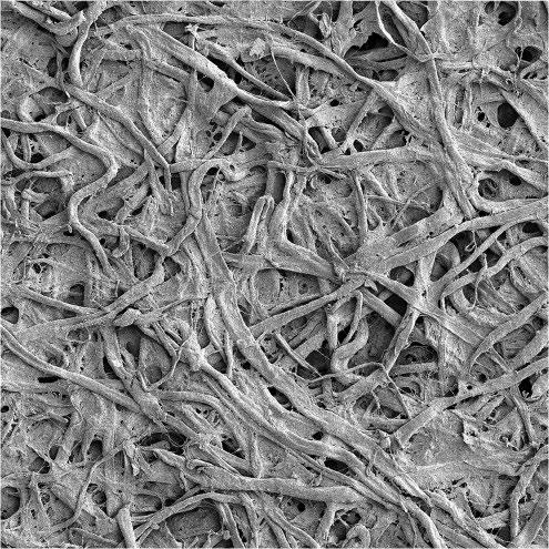
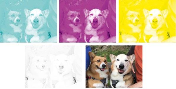
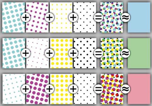
Print-on-paper consists of drops of colored ink impregnated into the paper fiber. It is straightforward to devise dyes and pigments that absorb red, green, or blue. To generate the color characteristics of print, the CMYK subtractive color system can be used (Figure 1.3). The colors in print are usually comprised of cyan (absorb red), magenta (absorb green), and yellow (absorb blue) (Figure 1.4). Black pigment (the K in CMYK) is also commonly used, as it is challenging to achieve a neutral black color by mixing cyan, magenta, and yellow.
Figure 1.1 Arches 100% cotton rag paper. Scanning electron microscope image @100×. Source: http:// paperproject.org [3] Used with permission of CJ Kazilek.

1.3
of an image into its CMYK components, and the final printed image. The absence of a color is white.
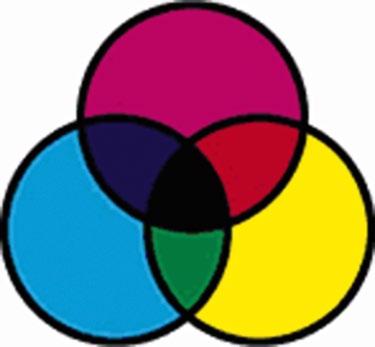
Figure 1.4 Subtractive color mixing. Cyan and magenta overlap to make blue, cyan, and yellow overlap to make green, yellow, and magenta overlap to make red, and all three mixed together provide black.
To achieve a wider color gamut, inkjet printing may use six or more colors to print. Additionally, spot color printing can deposit specialty inks (such as fluorescent pigments) that currently have no analog in emissive displays.
Depending on the industry, a variety of different color spaces and metrics have been developed for printed and reflected color. For example, the CIE 1976 (L*a*b*) color space is widely used to measure reflective colors and print. The human perception of lightness is measured by L*, which roughly scales as the cube root as the reflected luminance level.
For color reproduction in the print industries, the SNAP standard (Specifications for Newspaper Advertising Production) and SWOP standard (Specifications for Web Offset Publications) are widely used [1]. These print standards are rarely applied to electronic displays, though the advent of colored reflective displays approaching print-like appearance could change this situation.
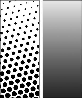
Grayscale in printing is achieved using halftones (Figure 1.5). Each dot on a printed page defines an area where smaller halftone dots are printed. The more halftone dots, the deeper the color or darker the black while white is the absence of halftone dots. The smaller the dots, the higher the resolution. Print is often defined in lines per inch.″ Some examples of everyday printed objects include:
● Newspaper (monochrome) – 65–100 LPI
● Books and magazines (color) – 120–150 LPI
● Art books (color) – 175–250 LPI
● Photorealistic inkjet printer (color) – 250–300 LPI
Likewise, the resolution-defined dot for color printing consists of multiple prints of smaller dots. The combination of different colors and black and the underlying brightness and color of the paper provide the specific color and lightness of that dot.
1.5
With inkjet printing, commercial printers can also control the size of the drop, such as achieving four different sizes (Figure 1.6). The number of achievable gray levels is a combination of the number and size of the printed dots within the equivalent printed pixel [6, 7].
1.4 Reflectivity and Viewing Angle
An important aspect of paper is that the image printed on the page appears to have constant lightness and color irrespective of the viewing angle and lighting conditions. If the paper is glossy, there may be some glare from the surface, but that reflectance rarely interferes with the user interacting with the page. The near-constant appearance of the printed page is representative of Lambertian reflectance. The underlying paper scatters light, impinging onto the surface from many angles and then reflected uniformly into all spatial angles. Whether the page is illuminated by a collimated source such as a light bulb in a dark room or a more uniform source such as a cloudy sky, the distribution of reflected light from the paper does
not change that much. Likewise, the amount of light scattered into the viewer’s eyes for a given spot on the paper is also constant with viewing angle [8].
1.5 Translating Print-on-Paper into Electronic Paper
With this background, we can examine why designing an electronic display with the appearance of high-quality print-on-paper is challenging.
1.5.1 Brightness
Electronic displays require a transparent front sheet as the top surface of the display. This top surface (usually plastic or glass) provides a flat dielectric interface with air and degrades the optics of electronic paper in several ways.
● A significant fraction (4–10%) of light is directly reflected off the display without interacting with the display medium. This reflected light is seen as glare and degrades the contrast of the underlying display to the viewer. This reflected light also reduces the available light scattered back to the viewer. Anti-reflective coatings can reduce this reflected light, but with added cost and sometimes compromises in durability.
● Even if there is perfect diffuse reflectance, a significant fraction of that light will be trapped by internal reflectance at the display-air interface [9]. For an EPD where the dielectric phase is somewhere in the range of 1.38–1.45, the maximum amount of light that can be outcoupled from a white scattering layer, with no other absorptive losses, is predicted to be no more than 65%. These incoming and outcoupling losses limit the potential brightness of an embedded Lambertian scatterer within an electronic paper display.
There are strategies to improve the luminance of scattering-based displays by incorporating focusing optical elements with the display itself. Fleming et al. have demonstrated a display that uses a retroreflective prismatic element within the display and a black electrophoretic colloid to control the reflection from this element [10, 11]. While the reflectivity of the micro prism layer will depend on the geometric details of the source illumination, in many lighting conditions, the micro prism itself provides optical gain, and the display can appear “whiter than white.”[12]. One display by Fleming et al., when illuminated by moderately collimated light, is reported to have an apparent brightness over 80%, with a 20: 1 contrast ratio. Fleming will describe more information on these types of displays in Chapter 4 of this volume. Further information about the metrology of measuring reflective display and e-paper will be described in Chapter 12.
1.5.2 Grayscale – Analog vs. Digital
High-quality images require grayscale, with 256 levels for each color channel being standard in emissive displays. Today, it is impractical to rely only on halftoning approaches to generate high-quality grayscale, which would require further subdividing each CMYK subpixel into an additional 4, 8, or 16 subpixels to maintain the native resolution. Instead, grayscale is generated using analog techniques, in which any pixel can be programmed to show intermediate reflective states between black and white. While many reflective display technologies, including EPDs, can show continuous grayscale within any pixel, maintaining accurate and uniform grayscale across all pixels is challenging. Analog gray levels are typically restricted to a number that enables uniform luminance without mura artifacts. For example, today’s commercial e-paper displays from E ink are limited to 16 analog levels of gray to achieve good uniformity. However the underlying technology is capable of more gray levels [13]. Sophisticated dithering algorithms have been developed to minimize perceptual errors, some of which have been examined for use in electronic displays [14]. Dithering is analogous in many ways to halftones in print. In an electronic display, dithering sacrifices resolution to give the appearance of intermediate gray levels or to suppress non-uniformities between pixels.
1.5.3 An Overview of Approaches to Color Electronic Paper
Many inventive approaches have been proposed to achieve electronic color paper. Some designs take advantage of an electro-optical medium that can change color at the subpixel level intrinsically. Other approaches use color filters with an otherwise colorless black and white effect. Accurate and uniform grayscale is essential for highquality images and is often very difficult to achieve.
Figure 1.7 illustrates an EPD in combination with color filters [15]. The function of a color filter is to absorb portions of the visible spectrum so that reflected light is colored. RGB or CMY primary colors can blend the primaries to provide an extended color range. Grayscale is adjusted by controlling the state of the reflective medium, similar to gray in black and white displays. These displays inevitably must make trade-offs between color saturation, color space coverage, and brightness. Reasonable brightness is usually achieved at the cost of color purity and a restriction of available colors.
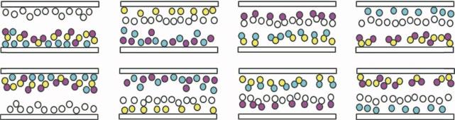
Another approach is the adoption of multiple color particles as electrophoretic elements [16, 17]. Different colors can be generated in each sub-pixel by mixing C, M, Y translucent particles with scattering white particles, as shown in Figure 1.8. This approach was firstly demonstrated by Fujifilm in 2012 [16], and later on by E ink [17], which named it Advanced Color ePaper (ACeP). The colored pigments have different electrophoretic mobilities and responsivities, which facilitate to shuffle the color particles with driving waveforms of different voltage and pulse widths. As shown in Figure 1.8, different primary colors can be presented by positioning the white particle layer above or underneath the translucent C, M, Y particles. Integrating the CMYW particles into a display unit, ACeP can present different colors and gray levels in each subpixel by controlling the driving waveforms.
Barrier film
Color filter
Common electrode
Transparent fluid
Sealing layer
Sub-pixel electrode R
Sub-pixel electrode B
Sub-pixel electrode G
Figure 1.7 Color electrophoretic display using B/W particles and subpixel color filters [15] / John Wiely & Sons.
These driving waveforms are complex, and frame rates are currently slower than other EPD approaches. Nevertheless, the multiple color particle design dramatically increases the color saturation and reflective luminance achievable compared to the color filter approach. Figure 1.9 compares the color performance of these two types of color EPD prototypes [16, 17].
Many other inventive approaches have tackled the problem of making the electro-optical medium capable of switching color. Controlled lateral migration of colored fluid and particles enables a bi-primary color system. This design allows a single pixel to be changed through mixtures of color states [19].
A variety of other physical phenomena can be used to modulate reflected light electrically. The following table describes several varieties of reflective displays that have been developed over the past several decades. The fact that so many technologies have been pursued shows both the interest in the electronic paper and the difficulty in achieving a paper-like display. We compare the various reflective display technologies in Table 1.1, showing the strengths and weaknesses of the different approaches. More information on these different technologies can be found in reviews [1, 2, 20] and other chapters in this book.
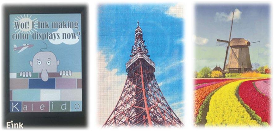
1.9 Prototypes of colored electrophoretic displays: the left image uses a color filter and front light, while the middle and right images use the multiple color particles design [16–18] A. [18] Ian French, et al. 2020; B.[16] Hiji N, et.al, 2012 / John Wiley & Sons, Inc.; C.[17] Telfer S J, MD Mccreary, 2016 / John Wiley & Sons, Inc.
Table 1.1 Summary of performance and other key factors for monochrome e-Paper technologies. Electrophoretic (commercial) Electrophoretic (eTIR)
Black %R3% [21]4% [10]3% [23]2%3 ∼ 4%[28]– 3–5%<3% [37]>3% [35]5% [35]5%2%6%2% [48]
Contrast ratio 15 : 1 [21]15 : 1 [10]23 : 1 [23]30 : 18 : 138.1 : 1 [31]>35 : 1 [35]>30 : 1 [37]15 : 18 : 1 [35]10 : 1>20 : 1 [43]13.3 : 120 : 1 [48]
Lambertian Yes Partial [10] YesYesYesYes
Partial[48] mono SNAP/ SWOP – Maybe SWOP [10] Maybe SWOP [23] SNAP–Maybe SWOP [30] SNAP [34]SNAPSNAP– Maybe SNAP Maybe SNAP [43] – –
Driving voltage 15 2–4 [11]<10 ∼5 [26]40–701.4 [31]15 ∼ 20 10–205–10(lab) < 4 (product) 25–40 [41] 5 ∼3 [43]4 ∼ 125[46]20
Bistable
Switching speed (msec)
drive
(Yes with matrix) YesYes yes
100’s (33 fps) 33 [10]15 (100 V) 30 (40 V) [24] <300 [27] <0.2 [29]<10 [33]10 ∼4 [38]0.01’s300 (vertical) 5 (inplane) [41] 51 [42]48 [43] ∼66 [47]20 ms
Greyscale approach Pulse Pulse [10]Analog/ Pulse PulseMultiwrite – Analog/Partial filling/Spatial dithering [36] PulseSpatial/ Temporal PulseAnalogHalftonePulseAnalog [49]
Grayscale bit level 4 4 [10]5 (∼30) [25] >4 [27]26 [30]4 4 [39]6 4 8 (60 Hz) 1 (6 Hz) [42] 2 [44]1 4 [49]
white point
LifespanGood – UnprovenUnprovenGood/ltd.Ltd./unprovenUnprovenUnprovenGoodGoodGoodGreatCommercialGood Power (Static) None None [10]Very lowVery lowNoneVery lowNone [34]NoneVery low NoneLowModerateNoneVery low Power (Video) Low Low [11]n/an/aLowVery highHigh HighHighModerateModerateLowHighVery low
Years of research Since 1969 [22]Reported 2018 [10] Since 2000 [1] Since 2009 [1] Since 2003 [1] Since 1989 [1]Since 2003 [1]Since 2009 [1] Since 1997 [1] Since 1994 [1] In mid 1980s [1] Since 2001 [1] – Since 1995 [48] MaturityMany productsPrototype [10]AM & PM demo AM demoESL product/ large PM Smart card products AM demoSegment product
There are several interesting aspects of Table 1.1 worth noting:
● Several e-paper technologies reach the reflective luminance of monochromatic SNAP (R ~ 60%), and a few of them move toward SWOP (R ~ 76%).
● The required driving voltages for many e-paper technologies are below 15 V, the maximum voltage provided by mainstream active matrix backplanes. As we will describe in a later section of this chapter, active-matrix backplane compatibility is a significant practical advantage.
● Many e-paper technologies have demonstrated a video speed response. However, it is important to note that high-quality video reproduction requires accurate grayscale performance, and accurate color if present. Not all technologies report this metric.
Later chapters in this book provide an up-to-date review of several essential e-paper technologies.
● In Chapters 2 and 3, the fundamental mechanisms, physical models, driving waveforms, and image processing of EPDs will be reviewed.
● Chapter 4 describes the Clear Ink EPD with a total internal reflective structure, enhancing the display’s brightness.
● Chapters 5 through 8 describe several different categories of reflective liquid crystal displays. Chapter 5 introduces reflective displays based on cholesteric liquid crystals that rely on Bragg reflection from helical liquid crystal structures. Chapter 6 introduces the zenithal bistable display (ZBD), which utilizes a grating-type surface alignment structure to achieve bistable reflective states. Chapter 7 introduces the memory-in-pixel (MIP) liquid crystal display technology, which realizes a bistable display by building a static memory circuit behind the reflective electrode for each pixel. Chapter 8 introduces optically rewritable (ORW) technology, which uses a photoalignment layer to control the orientation of the liquid crystals and spatially generate bright and dark reflective states.
● Chapter 9 reviews electrowetting display technology, in which an applied voltage causes the physical translation of a dyed fluid within the pixel, with a resulting optical appearance change.
● Chapter 10 discusses electrochromic technology, generating reversible color change through an electrochemical redox reaction.
● Chapter 11 introduces the phase transition material technology. Under optical or electrical energy stimulation, a phase change material cycles between amorphous and crystalline states with a resulting change in reflectivity.
● Chapter 12 reviews the metrology of reflective displays, providing the means to characterize the performance of different technologies.
It is fair to say that the electronic paper technology that has seen the greatest success in transitioning to high volume products is the microencapsulated EPD technology from E Ink Corporation. The next section of this chapter will review the historical development of EPDs, including the many inventions and milestones needed to achieve a competitive device. It took over 35 years to go from the initial concept, proposed by Xerox and Matsushita, to a successful high-volume product, the Amazon Kindle. During this development period, many engineers and scientists’ insights and hard work developed a combination of technical achievements and manufacturing scale that could enable competitive display products. Even with the baseline technology resolved, it still took the right product concept ready at the right time to lead to the commercial success of the Amazon Kindle. There are lessons to learn from observing how a laboratory curiosity was transformed into a technology and product that opened up a new industry.
1.6 The Allure of Electronic Paper vs. the Practicality of LCDs
The idea of a personal electronic device allowing user input and a display output screen is widely attributed to work done in the late 1960’s by Alan Kay of Xerox PARC. Kay coined the term DynaBook for the apparatus [50]. He also laid out many of the characteristics of the device, including that the visual output should be, at the very
1.7 TheEEolltion of Electrophoretic isplaay-ased ElectronicPaper 11
least, of higher quality than what can be obtained from newsprint. While electronic paper was not explicitly called out as a display medium, that analogy to newsprint is a natural precursor for an electronic book. Nevertheless, until the late 2000’s, liquid crystal displays dominated all implementations of personal electronic devices. Why did it take so long to develop attractive electronic paper products? One overwhelming factor is the success of the liquid crystal display. LCD technologies started development about the same time as EPDs, and one successful variant (the super twisted nematic, STN) LCD did not appear until over ten years later. Reflective LCDs’ suffered from poor brightness, poor contrast, and poor viewing angle characteristics. Nevertheless, LCDs can be matrix addressed to enable high pixel count, have reasonable response time, and be used in transmissive mode. LCDs were seen as “good enough” for many early applications. With volume production came incremental improvements in performance, reliability, and cost year-by-year. For a new electronic paper technology to take hold, it must outperform LCDs in multiple aspects and have an application important enough to attract investment in manufacturing at scale. For decades, no reflective display technology seriously challenged LCDs.