Get The pilot’s manual: ground school: all the aeronautical knowledge required to pass the faa exams
The Pilot’s Manual: Ground School: All the aeronautical knowledge required to pass the FAA exams and operate as a Private and Commercial Pilot (The Pilot’s Manual Series Book 2) – Ebook PDF Version
Visit to download the full and correct content document: https://ebookmass.com/product/the-pilots-manual-ground-school-all-the-aeronauticalknowledge-required-to-pass-the-faa-exams-and-operate-as-a-private-and-commercial -pilot-the-pilots-manual-series-book-2-eb/
More products digital (pdf, epub, mobi) instant download maybe you interests ...
Introduction to 80×86 Assembly Language and Computer Architecture – Ebook PDF Version
80+ Python Coding Challenges for Beginners: Python Exercises to Make You a Better Programmer. No Prior Experience Needed: 80+ Python Challenges to Launch ... Journey. Katie Millie
When it was time to take my private pilot written examination in 1955, my flight instructor handed me a pocket-size booklet. It was published by the Civil Aeronautics Administration (FAA’s predecessor) and contained 200 true/false questions (including answers).
“Study these well,” he cautioned with a wink, “because the test consists of 50 of these.”
As I flipped through the dozen or so pages, my anxiety about the pending examination dissolved into relief. Nothing could be easier, I thought. One question, for example, stated “True or False: It is dangerous to fly through a thunderstorm.” Really. (I passed the test with flying colors—but so did everyone else in those days.)
The modern pilot, however, must know a great deal more to hurdle today’s more challenging examinations. This has resulted in a crop of books developed specifically to help pilots pass tests. Unfortunately, some do little else, and the student’s education remains incomplete.
An exciting exception is The Pilot’s Manual series. These voluminous manuals provide far in excess of that needed to pass examinations. They are chock-full of practical advice and techniques that are as useful to experienced pilots as they are to students.
The Pilot’s Manuals are a refreshingly creative and clever approach that simplifies and adds spice to what often are regarded as academically dry subjects. Reading these books is like sitting with an experienced flight instructor who senses when you might be having difficulty with a subject and patiently continues teaching until confident that you understand.
Barry Schiff Los Angeles
Barry Schiff has over 26,000 hours in more than 300 types of aircraft. He is retired from Trans World Airlines, where he flew everything from the Lockheed Constellation to the Boeing 747 and was a check captain on the Boeing 767. He earned every available FAA category and class rating (except airship) and every possible instructor’s rating. He also received numerous honors for his contributions to aviation. An award-winning journalist and author, he is well known to flying audiences for his many articles published in some 90 aviation periodicals, notably AOPA Pilot, of which he is a contributing editor. ASA publishes several Barry Schiff titles.
About the Editorial Team
David Robson QTP
David Robson is a career aviator having been nurtured on balsa wood, dope (the legal kind) and tissue paper, and currently holds an ATP certificate with instructor ratings. He served as a fighter pilot and test pilot for the Royal Australian Air Force, completed a tour in Vietnam as a forward air controller flying the USAF O-2A, and was a member of the Mirage formation aerobatic team, the Deltas. After retiring from the Air Force, he became a civilian instructor and lecturer for the Australian Aviation College, and editor for Aviation Safety Digest, which won the Flight Safety Foundation’s international award. He was awarded the Australian Aviation Safety Foundation’s Certificate of Air Safety.
Richard Coffey
Richard Coffey is a commercial pilot and flight instructor with instrument, multiengine, and sea plane privileges. He has also been an aviation writer and editor since 1976 and is the author of the Skylane Pilot’s Companion (1996). He has written for Airports Services Management magazine, IFR, Aviation Consumer, Aviation Safety and IFR magazines. He regularly flies Cessna 210s and 182s, although he has a weakness for older Beech Bonanzas and has owned an M model.
Dr. Dale DeRemer
Dr. DeRemer was recognized as “Seaplane Pilot of the Year” by the Seaplane Pilots Association, and inducted into the EAA-NAFI Flight Instructor Hall of Fame. He was named “Professor Emeritus of Aviation” by the University of North Dakota College of Aerospace Sciences after 20 years of teaching aviation subjects at the university level. During his career, he has served as corporate pilot, agricultural pilot and chief pilot for his own and other companies. He has logged over 20,000 hours total time in general aviation aircraft of many types. Dale holds ATP, CFI-A, CFI-H, CFI-I and MEI licenses with single- and multi-engine land and sea, rotorcraft-helicopter and instrument ratings.
Sean Elliott
Sean is the President and CEO of the National Association of Flight Instructors (NAFI), dedicated to promoting and elevating the status and quality of the Certificated Flight Instructor. Sean is also the Director of Aircraft Operations for the Experimental Aircraft Association (EAA), overseeing all warbird, vintage, and experimental aircraft flight operations and is himself an active pilot and training instructor in everything from a Ford Tri-Motor to a Boeing B-17G Bomber. Sean has over 5,300 hours of dual instruction given. He holds NAFI’s Master CFI designation, CFI, CFI-I, CFMEI, Gold Seal, AGI, IGI, and BFI for ultralight instruction.
Craig Kilcourse
Craig Kilcourse is an active Flight and Ground Instructor in the Seattle, Washington area; He has contributed to marketing, product design and testing as well as technical support for ASA products and software. Craig holds a B.A. in Economics from Virginia Tech.
Jeanne MacPherson
Bureau Chief, Safety and Education for the Montana Aeronautics Division of Helena, Jeanne is also the Chief Pilot and Mountain Flight Instructor. She coordinates air search for the State of Montana and coordinates Mountain Search Pilot Clinics, Flight Instructor Refresher Clinics, Winter Survival, Density Altitude Clinics, Aviation Education Workshops, and Aviation Careers Programs. Jeanne is a Young Eagles Flight Leader (EAA) and has flown over 2,900 students; she is the recipient of the 2003 EAA Freedom of Flight Award, 2002 Women in Aviation Educator of the Year Award, and 2000 FAA Aviation Educator of the Year for the Northwest Region.
Dennis Newton
Dennis Newton holds ATP and CFI certificates, and is an FAA-Designated Engineering Representative Flight Test Pilot for both small and transport airplanes. A few of Mr. Newton’s past achievements include meteorologist, weather research pilot, and engineering test pilot; he has also served as a consultant to government and industry on icing certification and flight testing. Dennis Newton is the author of numerous papers and aviation magazine articles on icing and other weather topics. He holds a B.S. in Engineering and an M.S. in Meteorology. Mr. Newton is also a member of the American Institute of Aeronautics and Astronautics, and the Society of Experimental Test Pilots.
Dr. Phil Poynor
Phillip J. Poynor, MCFI, is an associate professor and chair of the Aviation Division at Daniel Webster College in Nashua, NH. He holds an ATP pilot certificate and has captained on Part 135 operations. He is an FAA Gold Seal Flight Instructor, and is a licensed attorney in the state of New York. Prof. Poynor was named the FAA/Industry 2001 National Flight Instructor of the Year and won the NATA Excellence in Pilot Training Award in 1998. He is a NAFI Master CFI.
Barry Schiff
Barry Schiff has over 26,000 hours in more than 300 types of aircraft. He is retired from Trans World Airlines, where he flew everything from the Lockheed Constellation to the Boeing 747 and was a check captain on the Boeing 767. He earned every available FAA category and class rating (except airship) and every possible instructor’s rating. He also received numerous honors for his contributions to aviation. An awardwinning journalist and author, he is well known to flying audiences for his many articles published in some 90 aviation periodicals, notably AOPA Pilot, of which he is a contributing editor.
Warren Smith
James Warren Smith is the Vice President of Flight Operations and Chief Pilot for the Flightstar Corporation located in Savoy, IL. With over 8,000 hours flown and over 3,000 hours of flight training given, Warren currently flies a Falcon 900 internationally and serves as a Designated Pilot Examiner (DPE) for the FAA. Warren has been a certificated flight instructor (CFI) for over 20 years and has served as the chief flight instructor for several 141 flight schools. In addition, Warren has served as Chairman of the National Air Transportation Association (NATA) Flight Training Committee dealing with flight training issues on a national level.
Jackie Spanitz
Jackie earned a B.S. in Aviation Technology and Operations from Western Michigan University and earned a M.S. from Embry-Riddle Aeronautical University. As Curriculum Director for ASA, Jackie oversees new and existing product development, ranging from textbooks and flight computers to computer-based tutorials, and integration of these products into curricula. She also conducts aviation research as well as product development and project management. She holds Flight and Ground Instructor Certificates. Jackie is the author of Guide to the Biennial Flight Review, the technical editor for ASA’s Test Prep series, and has written for numerous aviation publications.
Richard Taylor
Richard L. Taylor is an award-winning author of many articles and 14 aviation books. He retired from the Air Force Reserve as a major, having earned Command Pilot status. Now associate professor emeritus, Taylor was director of flight operations and training and taught at all levels of the flight curriculum at the Ohio State University. He is the founder and editor of The Pilot’s Audio Update, a monthly audio tape cassette service published continuously since 1978. Taylor has accumulated nearly 13,000 hours of pilot time in a wide variety of aircraft including gliders, helicopters, amphibians, turboprops, jets, and most general aviation light airplanes. He remains active in accident investigation and as an aviation consultant in Dublin, Ohio.
Dr. Mike Wiggins
Mike Wiggins has been with Embry-Riddle Aeronautical University for over 27 years. He is currently a tenured professor in the Aeronautical Science Department and the director of the newly created campus Center for Teaching and Learning, having taught in the classroom, been a member of the ERAU Flight Department, and active with the National Intercollegiate Flying Association (NIFA). He holds a Doctorate in Education from Oklahoma State University, a Masters Degree in Business Administration, and a Bachelor of Science Degree in Aeronautical Science from EmbryRiddle Aeronautical University. He holds an ATP certificate with Boeing 757 and 767 type-ratings, and flight instructor and ground instructor certificates.
Tom Wild
Thomas Wild is a full professor at Purdue University who holds an Aviation Maintenance Technician certificate with Inspection Authorization. He is also a Designated Mechanics Examiner, and a Flight Engineer. With numerous awards for his contributions to education, Tom has been teaching aviation technology at Purdue University for more than 25 years. He is the Managing Editor for the ATEC Journal, has written many articles, textbooks, and conducted seminars for the industry. He is a past member of the Board of Directors for Professional Aviation Maintenance Association (PAMA).
Introduction
You are about to become a flyer, and join the worldwide family of pilots. To do this safely, you need some knowledge, and the aim of The Pilot’s Manual is to introduce you to this knowledge in an easy-to-follow manner that is both practical and thorough, so that you will fly the airplane confidently and pass the FAA Knowledge Exams with flying colors.
You will learn to be a safe pilot, to take off and fly in the vicinity of your home airport, and to navigate around the country without getting lost or tangled up with thunderstorms and airliners.
The Pilot’s Manual has been written not only to help you to pass the FAA Knowledge Exams, but also for you to keep on your bookshelves as a ready reference containing items of practical importance to a pilot. The team involved in producing The Pilot’s Manual includes many very experienced pilots from a wide range of backgrounds—flight instructors, ground instructors, mountain-flying experts, professors of aviation, meteorologists, FAA inspectors, examiners, air force pilots, naval aviators, airline pilots and others. The accumulated knowledge between these covers is yours for the taking!
Ground School is divided into five sections and introduces you to:
• aerodynamics —the basic principles of flight and airplane design;
• the airplane —the piston engine, airplane systems and flight instruments;
• airplane and pilot performance —the factors which affect takeoff and landing performance, climbing and the cruise, how to safely load your airplane and basic physiology so that you can maximize your personal performance;
• weather —the main processes of weather and how to interpret charts and forecasts; and
• flight operations —the Federal Aviation Regulations (to keep everyone safe), the basic principles of navigation, charts, airspace and airports, flight planning and radio navigation.
This manual is designed for both the Private and Commercial Pilot.The main body of each chapter contains the knowledge required for the Private Pilot Certificate, with review questions. The questions highlight important points and give you practice at typical Knowledge Exam questions.
Additional Commercial Pilot Certificate knowledge, with review questions is included. It is not necessary for the prospective Private Pilot to read these additions, but we hope, when you see how straightforward they are, you will be encouraged to further your aviation knowledge at some stage and take the Commercial Pilot Knowledge Exam. If you plan to go straight to Commercial, this book is ideal for you.
Note. Additions intended only for students studying for their CPL are indicated by a blue line across the top of the relevant text and the letters “CPL” on the outer margin. Subsequent pages are also indicated in this way when appropriate. The end of a CPL-only section is indicated with the text “End CPL” in the outer margin (and a blue line underneath the text should that text fall midpage). No “End CPL” indication is given if the end of a chapter coincides with the end of a CPL-only section.
A Few Points on Studying
Keep your study periods short and intense. Quietness, good lighting, and a clear and fresh mind are important to efficient study. Leisure is important too. Occasional walks and breaks for relaxation are beneficial to study, as is a day a week away from it all. Make your own notes and summaries as you read through our text. The summary that you prepare is a most important aid to your learning. We suggest you work your way through the manual chapter-by-chapter, making your own notes and completing each set of review questions as you go. The reviews are not difficult because the knowledge required is in the text. The review questions are designed to give you confidence in your own knowledge and ability while giving you practice for the Private or Commercial Knowledge Exams.
The FAA Knowledge Exams consist of multiple-choice questions which are quick and easy to process. However, multiple-choice questions are not a good learning aid as they present you with a choice of answers, some of which are wrong.To continually read incorrect statements is confusing, so in our reviews we question you in a more positive manner, while retaining some multiple-choice questions in the examination style for your practice.
Our advice when working multiple-choice questions is, prior to reading through the selection of possible answers, think in your own mind what the answer might be. Then read through the choices and quite often you will find the answer you already have in mind is among them. If not, then proceed to eliminate the incorrect statements.
Please note that if you are preparing for the Commercial Knowledge Exam you should complete both the private and commercial reviews.
Note. Italics are used throughout the text to highlight significant terms and concepts.
Conclusion
The Pilot’s Manual: Ground School is designed to develop an in-depth understanding of the main facets of aviation. Not only will it help you pass the Knowledge Exams easily, it will also provide an excellent basis for becoming a competent and safe pilot, regardless of whether you plan to use your skills for personal recreation and travel, or in a full-fledged career as a flight instructor or with the airlines.
Best wishes for success in your Knowledge Exams and practical flying.
Aerodynamics
1Forces Acting on an Airplane
2Stability and Control
3Aerodynamics of Flight
Forces Acting on an Airplane
Like all things, an airplane has weight, the force of gravity that acts through the center of the airplane in a vertical direction toward the center of the earth. While the airplane is on the ground, its weight is supported by the force of the ground on the airplane, which acts upward through the wheels.
During the takeoff roll, the task of supporting the weight of the airplane is transferred from the ground to the wings (and vice versa during the landing). While in level flight, the weight of the airplane is supported by the lift force, which is generated aerodynamically by the flow of air around the wings. In addition, as the airplane moves through the air it will experience a retarding force known as drag, which, unless counteracted, will cause the airplane to decelerate and lose speed.
In steady (unaccelerated) straight-and-level flight, the drag (or retarding force) is neutralized by the thrust (figure 1-2). In most smaller airplanes, thrust is produced by the engine–propeller combination; in pure-jet airplanes, the thrust is produced by the gas efflux, without the need for a propeller.
1
In figure 1-3, the forces are equal and opposite, canceling each other out, so that the resultant force acting on the airplane is zero, and it will neither accelerate nor decelerate. In this situation the airplane is in a state of equilibrium:
• weight is equal to lift, and acts in the opposite direction; and
• drag is equal to thrust, and acts in the opposite direction.
During steady (unaccelerated) flight the four main forces are in equilibrium and the airplane will continue in level flight at the same speed.
For the type of airplane you are likely to be flying during your training, the amount of the lift (and therefore the weight) during cruise flight will be approximately 10 times greater than the drag (and thrust). This relationship of lift to drag is very important and is referred to as the lift/drag ratio. The L/D ratio in this case is 10 to 1.
If the airplane is to accelerate in level flight, the thrust must exceed the drag; if the airplane is to be slowed down in level flight, the thrust must be less than the drag. A state of equilibrium does not exist during acceleration or deceleration.
1-3 The four main forces are in equilibrium during unaccelerated flight.
Figure
Figure 1-2
The airplane is supported by the ground, and in the air by lift. Ground reaction
Thrust counteracting drag
Figure 1-1 Drag counteracted by thrust.
CPL
Weight
Gravitational Force (Weight)
Gravity is the downward force attracting all bodies vertically toward the center of the earth.The name given to the gravitational force is weight, and for our purposes it is the total weight of the loaded airplane. This weight is called gross weight , and it may be considered to act as a single force through the center of gravity (CG).
The CG is the point of balance. Its position depends on the weight and position of the various parts of the airplane and the load that it is carrying. If the airplane were supported at its center of gravity, the airplane would be balanced.
The weight of an airplane varies depending on the load it has to carry (cargo, baggage, passengers) and the amount of fuel on board. Airplane gross weight will gradually decrease as the flight progresses and fuel is burned off. The magnitude of the weight is important and there are certain limitations placed on it—for instance, a maximum takeoff weight will be specified for the airplane. Weight limitations depend on the structural strength of the components making up the airplane and the operational requirements the airplane is designed to meet.
The balance point (center of gravity) is very important during flight because of its effect on the stability and performance of the airplane. It must remain within carefully defined limits at all stages of the flight.
The location of the CG depends on the weight and the location of the load placed in the airplane. The CG will move if the distribution of the load changes, for instance by transferring load from one position to another by passengers moving about or by transferring fuel from one tank to another. The CG may shift forward or aft as the aircraft weight reduces in flight, such as when fuel burns off or parachutists jump out.
Wing Loading
Both weight and balance must be considered by the pilot prior to flight. If any limitation is exceeded at any point in the flight, safety will be compromised. (A detailed study of weight and balance appears in chapter 11.) A useful means of describing the load that the wings carry in straight-and-level flight (when the lift from the wings supports the weight of the airplane) is wing loading , which is simply the weight supported per unit area of wing.
Wing loading weight of the airplane wing area - =
Example 1-1
An airplane has a maximum certificated weight of 2,600 pounds and a wing area of 200 square feet. What is its wing loading at maximum weight?
The position of the CG is shown in diagrams with a centroid symbol:
Balancing force
Figure 1-4
acts downward through the center of gravity (CG).
Airflow and Airfoils
An airfoil is a surface designed to lift, control, and propel an airplane. Some well-known airfoils are the wing, the horizontal stabilizer (or tailplane), the vertical stabilizer (or fin), and the propeller blades. A wing is shaped so that as the air flows over and under, a pressure difference is created—lower pressure above the wing and higher pressure below the wing—resulting in the upward aerodynamic force known as lift. The wing also bends the free stream of air, creating downwash. The total reaction has a vertical component to lift the aircraft or change its flight path, and it has a rearward component, drag, which resists the movement of the wing through the air.
The airplane’s control surfaces—ailerons, elevator and rudder— form part of the various airfoils.You can move these to vary the shape of each airfoil and the forces generated by the airflow over it. This enables you to maneuver the airplane and control it in flight. These control surfaces also operate based on Newton’s Third Law of Motion, which says that every action has an equal and opposite reaction. By deflecting the free stream of air that flows over them, control surfaces cause the airplane to roll, yaw or pitch as the reaction.
The wing shape can also be changed by extending the flaps to provide better low-speed airfoil characteristics for takeoff and landing.
Airflow Around an Airfoil
The pattern of the airflow around an airplane depends on the shape of the airplane and its attitude relative to the airflow. There are two airflow types: streamline flow and turbulent flow.
Laminar Flow
If successive molecules or particles of air follow the same steady path in a flow, then this path can be represented by a line called a streamline. There will be no flow across the streamlines, only along them. There is no turbulence or mixing, hence the name laminar (layered) flow. At any fixed point on the streamline, each particle of air will experience the same speed and pressure as the preceding particles of air when they passed that particular point. These values of speed and pressure may change from point to point along the streamline. A reduction in the speed of streamline flow is indicated by wider spacing on the streamlines, while increased speed is indicated by decreased spacing of the streamlines. The existence of streamline flow is very desirable around an airplane because streamlined flow offers the least drag.
Figure 1-5 Airfoil shape.
Figure 1-6 Left aileron.
Figure 1-7
Vertical stabilizer and rudder.
Figure 1-8 Wing flaps.
Figure 1-9 Laminar flow.
Turbulent Flow
In turbulent flow, the airflow does not follow a streamlined pattern. Succeeding particles of air may travel a path quite different to the preceding parcels of air. This turbulent flow is also known as unsteady flow, vortices or eddying, and is an undesirable feature in most phases of flight. The point where the airflow around a surface becomes turbulent is called the transition point . The point where the turbulence is so severe that the airflow separates from the surface of an airfoil is known as the separation point (see figure 1-10).
The wing of an airplane pushes and induces the air downwards and forwards, because of its shape, angle of attack, and speed. The reaction is an upward/rearward force called the total reaction. The upward component of this reaction lifts the airplane (i.e. it overcomes gravity), and the rearward force (drag) is the force that must be overcome by the engine and propeller.
How the wing generates the action and total reaction has been a subject of theoretical debate for many years.You may hear theorems of lift due to:
•Bernoulli’s principle (pressure inequalities);
•circulation theory (vortices); and
•Coanda effect (downwash).
The end result of these is that the passage of the wing causes downwash, and the reaction causes lift and drag (Newton’s third law). The most common explanation of lift is given by Bernoulli’s principle, but this theorem is by no means the whole story.
Energy and Pressure
There are two types of energy:
•potential energy (due to height – for example, the pressure in a faucet is a function of the relative height of the water tank); and
•kinetic energy (due to speed).
An airplane at 10,000 feet has the potential to dive and accelerate. An airplane at low altitude and high speed has the capacity to zoom up to a higher altitude. Thus any body has a total bank of energy that can be exchanged as speed or height (with some losses in the exchange process).
For a gas, mass equates to density and energy equates to pressure. The pressure forces exerted by air are caused by:
•static pressure (a function of height); and
•dynamic pressure (due to speed).
Static pressure is caused by gravity. The stack of air molecules in the earth’s atmosphere causes the lower molecules to be squashed (less volume, greater density) and the upper molecules to be relaxed (more volume, less density). Dynamic pressure is caused by air moving against an object (wind and turbulence) or by an object trying to move through the air.
Figure 1-11 Total reaction.
Total reaction Lift Drag
Figure 1-10 Turbulent flow.
The forces experienced by an aircraft are a combination of static and dynamic pressure. If the aircraft is stationary, it experiences only static atmospheric pressure (and any dynamic pressure due to wind). Static pressure is equal in all directions—up, down and all around. As soon as the airplane moves through the air, the static and dynamic pressures change, while the total pressure remains constant. Thus for any place on the aircraft when the dynamic pressure increases, the static pressure drops. If the dynamic pressure reduces, the static pressure increases. This is reflected around an airfoil, as shown in figure 1-12.
Leading-edge stagnation point
Area of reduced static pressure
Area of increased pressure Downwash
Figure 1-12
Pressure around an airfoil.
The dynamic pressure of a parcel of air moving relative to an object is a function of its density. This density (and velocity) generates a force on any object that tries to move through it. This force, when calculated per unit of surface area, is called dynamic pressure. If you hold your hand up in a strong wind or out of the window of a moving automobile, air pressure is felt because of the air striking your hand and flowing around it. This pressure is dynamic pressure—pressure caused by the relative movement between your hand and the air.
Dynamic pressure (represented by the symbol “q.”) involves air density (mass per unit volume) which is denoted by the Greek letter rho (ρ). The more dense the air, the greater the dynamic pressure:
Dynamic pressure (q) = ½ρ × velocity-squared = ½ ρV2
The strength of dynamic pressure therefore depends on:
•the velocity (speed in a particular direction) of the body relative to the air; and •the density of the air.
Bernoulli’s Principle
The production of the lift force by an airfoil may be explained by Bernoulli’s principle also known as the venturi effect. Daniel Bernoulli (1700–82) was a Swiss scientist who discovered this effect. A fluid in steady motion has a total energy. Air is a fluid, and if we assume it to be incompressible, it behaves as a so-called “ideal” fluid. Bernoulli’s principle states that for an ideal fluid the total energy in steady streamline flow remains constant. Therefore:
Potential energy + kinetic energy =constant total energy
Within any steady streamline flow the total energy content will always remain constant, but the relative proportions of pressure energy and kinetic energy can vary. If kinetic energy increases because of a greater speed of flow, then potential energy will decrease accordingly. This is explained by Bernoulli as fluid flowing through a tube. The mass flow (total energy) is constant. If the opening is restricted (like the nozzle in a garden hose), the velocity is increased.
Bernoulli’s principle is the easiest nonmathematical way to understand the production of lift (and drag) by an airfoil.
Total energy in a steady streamline flow remains constant.
10
40
40
40
pressure is greater in dense air.
The faster an automobile drives or the stronger the wind blows, the stronger the dynamic pressure that you feel on your hand. This is because of the greater number of air molecules that impact per second.
Note. It is the relative velocity of the airplane and the airflow that matters. The force is the same whether it is the airplane moving through the air or the air is flowing over the airplane.
At the same speed, the denser the air, the more molecules per second that will strike your hand and so the greater the dynamic pressure. Density changes with altitude and temperature.
Note. Bernoulli’s principle may be used to explain many aspects of aerodynamics, but only if it is assumed that air is incompressible. At the private- and commercial-pilot level, such an assumption is valid because we are mainly concerned with airplanes that operate at relatively slow speeds and at altitudes below 10,000 feet. At higher speeds and altitudes, compressibility of air must be accounted for, but this is only applicable when you are studying at the Airline Transport Pilot (ATP) level.
Lift and Thrust
Pressure is force per unit area—pounds per square inch (psi). This force around an airplane is significant. Static pressure alone acts on all sides of the airplane and thus cancels itself, until we use dynamic pressure and the resultant differences in static pressure to our advantage. It is an imbalance of forces that allows the airplane to fly.The propeller causes reduced static pressure ahead and increased static pressure behind.The force is called thrust and drives the airplane forwards. The airfoil section of the wing accelerates the air; this causes a downwash and a change in static pressure between the lower and upper surfaces. This is sufficient to carry the aircraft and to maneuver it (change its flight path). The control surfaces cause the change in flight path.
Airspeed
Dynamic pressure (q) and the term ½ ρV2 are very important in aviation. The airspeed indicator shows indicated airspeed (IAS), which is not a real speed but a measure of dynamic pressure. Since dynamic pressure is related to air density, the real speed of the airplane relative to the airflow can only be calculated if the change in density due to altitude or temperature is recognized. This corrected speed is known as true airspeed (TAS or V). Although indicated airspeed is of most concern to you when flying, you will need to calculate true airspeed for measuring time, fuel, and distance.
Figure 1-13
Dynamic pressure increases with airspeed.
Figure 1-14
Dynamic
Airfoils
All parts of the airplane contribute positively or negatively to the total forces of lift and drag, but it is the airfoil of the wing that is specifically designed to provide the lift needed to support the weight of the airplane in flight. If a thin, flat metal plate is oriented parallel to a streamline airflow, it causes virtually no alteration to that airflow, and consequently experiences no reaction (aerodynamic force). If, however, the plate is inclined with respect to the airflow, it will experience a reaction that tends to both lift it up and drag it back. This is the same effect that you feel if you hold your hand out the window of a moving vehicle. The amount of reaction depends on the relative speed and the angle between the flat plate (or your hand) and the airstream.
Because of the angle of the plate to the airflow, the straight-line streamline flow of the air is disturbed. A slight upwash is created in front of the plate, causing the air to flow through a more constricted area, almost as if there was an invisible venturi above the plate. As it passes through this constricted area, the air speeds up. The velocity increase produces a decrease in static pressure (Bernoulli’s principle).
The static pressure above the plate is now lower than the static pressure beneath the plate, causing a net upward and rearward reaction. After passing the plate there is a downwash of the airstream. Note that if the angle of the flat plate to the airflow becomes too large, the streamline airflow breaks down resulting in less lift and more drag. See figure 1-15.
Figure 1-15 Airflow can lift a flat plate (but not efficiently).
The reaction, or aerodynamic force, on the plate caused by its disturbance of the airflow has two components:
•one at right angles to the relative airflow, known as lift; and
•one parallel to the relative airflow, opposing the relative motion, known as drag.
Airfoil Shape
A flat plate is not the ideal airfoil shape because it breaks up the streamline flow, causing eddying (turbulence), with a loss of lift and a great increase in drag. In addition, it is difficult to construct a thin, flat wing (no strength, no internal structure).
Figure 1-16 Examples of various airfoil shapes.
A cambered airfoil surface not only generates more lift and less drag compared to a flat plate, it is also easier to construct in terms of structural strength. Airfoils can have many cross-sectional shapes. Airplane designers choose the shape with the best aerodynamic characteristics to suit the role of the airplane.
Camber
Camber is curvature. Aviation pioneers, such as Wilbur and Orville Wright, experimented with different curved (cambered) shapes and found that the degree of curvature, the point of maximum curvature, and the ratio of thickness to length were critical. Later designers found that the shape of the upper curvature was more important than the lower curvature, and therefore they could have a thicker, lighter, stronger wing with internal storage capacity for fuel and structure with no aerodynamic penalty. Thick wings with a large camber have a good lifting ability, making them suitable for low-speed flight. The position of greatest camber is usually about 30 percent back from the wing leading edge. As camber increases, the airflow path lengthens, resulting in the airflow speeding up, static pressure reducing and lift and drag increasing.
Wings with less camber give a better cruise performance but a higher takeoff and landing speed (and distance). Aircraft and airfoil design is a compromise to suit customers’ requirements.
Mean Camber Line
The mean camber line is the line drawn halfway between the upper and lower surfaces of the airfoil cross-section. This line gives a picture of the average curvature of the airfoil.
Camber
The camber is the maximum distance between the mean camber line and the chord line.
Chord Line
The chord line is the straight line joining the leading edge and the trailing edge of the airfoil or, in other words, the straight line joining the ends of the (curved) mean camber line.
The Chord
The length of the chord line is called the chord of the wing. It varies from the wing root to the wing tip, so we use the average (mean) chord.
Camber Chord line
Mean camber line
Same camber, different thickness Symmetrical
Figure 1-17 A cambered airfoil with internal structure.
Figure 1-18 More camber, more lift, less drag.
Figure 1-19 Mean camber line.
Figure 1-20 Camber.
Figure 1-21 Chord line.
Mean camber line
Chord line
Chord
Camber
Aerodynamic Forces
In normal flight, the static pressure over most of the upper surface of the airfoil is slightly reduced when compared with the normal static pressure of the airflow well away from the airfoil. The static pressure beneath much of the lower surface of the airfoil is greater than that on the upper surface, because a greater number of air molecules are impacting the airfoil’s lower surface and the airflow is being slowed down. This pressure difference is the origin of the total aerodynamic force exerted on the airfoil, with the greater contribution coming from the upper surface.
In the same way that the total weight of an airplane can be considered to act through a single point—the center of gravity—the aerodynamic forces on an airfoil can be considered to act through a single point known as the center of pressure (CP) or center of lift.
It is convenient for us to consider the aerodynamic force (total reaction ) in its two components: lift and drag:
• lift is the sum total of the components of the aerodynamic force at right angles, or perpendicular, to the relative airflow; and
• drag is the total of the component of the aerodynamic force parallel to the relative airflow and opposing motion.
The center of pressure is the point through which the equivalent single force (TR) would act to cause the same effect as all the component forces distributed over the wing.
The relative airflow, or relative wind, refers to the relative motion between a body and the remote (free stream) airflow—that is, the airflow far enough away from the body not to be disturbed by it. The relative airflow is the direction opposite to the flight path of the airplane.
The angle of attack is the angle between the chord line of an airfoil or wing and the remote relative airflow. It is represented by the Greek letter α (alpha).
Figure 1-22 The production of lift and drag.
Same airfoil, same situation
Figure 1-23
The aerodynamic force acts through a point on the wing called the center of pressure.
Note the following.
1. Do not confuse the pitch attitude of the airplane (relative to the horizontal) with the angle of attack of the airfoil (relative to the remote airflow). See figures 1-25 and 1-26.
Flightpath (and relative airflow)
Different pitch attitude
Same angle of attack
Same attitude
Different angles of attack
Figure 1-25 Same angle of attack, but different pitch attitudes.
Flightpath (and relative airflow)
3
2
Figure 1-26 Same pitch attitude, but different angles of attack.
2. Do not confuse angle of attack with angle of incidence —the angle at which the wing is mounted onto the fuselage, relative to the longitudinal axis. The angle of incidence is fixed at construction (figure 1-27), while the angle of attack changes in flight.
Angle of incidence
Figure 1-27 The angle-of-incidence is fixed during design and construction.
Chord line of wing
Longitudinal axis of airplane
Lift and Drag from a Typical Wing
The amount of lift that a wing can produce depends on:
•the lifting efficiency of the wing (angle of attack, shape, airfoil section, camber and flaps);
•dynamic pressure; and
•wing area.
Lift= lifting efficiency of the wing and its angle of attack × dynamic pressure × surface area
L=CL × ½ρV2 × S
The equation shows that for constant lift, a reduction in airspeed must be countered by an increased lifting ability of the wing (increase in angle of attack). Conversely as airspeed is increased, to maintain level flight the pilot will need to lower the airplane’s nose to reduce the angle of attack and decrease the wing’s lifting ability. Also notice that if the lifting ability and area of the wings remain constant, and the airspeed doubles, the lift will increase four times (two squared).
The drag depends on the shape, angle of attack, and smoothness, the square of the true airspeed:
Drag=shape × dynamic pressure × surface area
D=CD × ½ρV2 × S
Experimentally, it can be shown that the aerodynamic force, and therefore the lift, depends on:
•wing shape (airfoil section and flap position);
•angle of attack;
•air density ( ρ);
•velocity—true airspeed (V × V, or V2); and
•wing surface area (S).
Velocity of the airflow and air density ( ρ) are combined in the expression for dynamic pressure : ½ρV2, which is related to indicated airspeed. Putting this together with the wing surface area (S) we obtain the equation:
Lift =(some efficiency factor) × ½ρV2 × S
We use the efficiency factor to cover the other variables, especially the wing shape and the angle of attack. This factor is called the coefficient of lift (CL), which is really the lifting ability of the wing at that particular angle of attack. Therefore:
Lift =CL × ½ρV2 × S
Lift depends on the angle of attack and indicated airspeed.
Apart from the extension of flaps, the wing shape is fixed, and any change in CL can only be caused by a change in angle of attack. At cruise speed, most of the lift is due to dynamic pressure, as the angle of attack is low. To fly slowly, the dynamic pressure is low, and so a high angle of attack is needed to generate the same lift. This interrelationship between angle of attack and airspeed is very important. By using the equation:
Figure 1-28
Coefficient of lift versus angle of attack; each angle of attack produces a particular CL value.
and measuring L, V, ρ and S, we can calculate the value of CL and develop a graph or curve of CL versus angle of attack, known as the lift curve (figure 1-28), or C L/α curve.
For a given wing, the angle of attack is the major controlling factor in the distribution of the static pressure around the wing. This determines the lift force that is generated. The actual value of CL will therefore differ according to the angle of attack.
Each airfoil shape has its own particular lift curve which relates its CL to angle of attack. We will consider an average cambered wing like that found on a typical training airplane such as a Cessna 172:
•at 0° angle of attack the cambered wing creates some lift and has a positive CL;
•at about –4° angle of attack the lift is zero; and
•as the angle of attack increases, the CL increases proportionally up to about 12° or 13° angle of attack and then falls off as the airflow separates before the stall.
At higher angles of attack, the curve starts to lean over, until at the stall angle (about 16° in this case) the C L begins to decrease. This occurs when the airflow is unable to remain streamline over the wing’s upper surface, separates from the wing surface, and breaks up into eddies. Notice that the maximum CL (the maximum lifting ability of the wing) occurs immediately prior to the stall.
Mean camber line (curved)
Chord line
Cambered airfoil
Chord line and mean camber line (co-linear)
Symmetrical airfoil
Figure 1-29
A cambered and a symmetrical airfoil.
Lift from a Symmetrical Airfoil
An equally symmetrical airfoil is chosen for a surface that has to generate positive or negative forces. Typical symmetrical airfoils are the vertical stabilizer and some horizontal stabilizers. The mean camber line of a symmetrical airfoil is a straight line because both surfaces have identical curvature. Therefore the chord line and mean camber line are identical.
The lift curve for a symmetrical airfoil will give a CL = 0 (and zero lift) at 0° angle of attack, see figure 1-30. This is because the streamlines follow mirror-image paths and therefore the airflow on both sides of the airfoil has the same velocity and static pressure. The center of pressure will not move as the angle of attack of a symmetrical airfoil is increased (whereas it moves forward on a cambered airfoil).
Changing Wing Area
Another factor that can alter lift is the wing area, S. If we could increase S, then we would obtain the same lift at a slower airspeed. Some flaps, such as Fowler flaps, increase the wing area as they are extended. Other basic flaps simply change the crosssection of the wing as they are extended. All flaps cause changes in lift and drag, and consequently have an effect on the value of the L/D ratio. Some flaps create slots that enhance the airflow and improve efficiency at low speed.
Pressure Distribution and CP Movement
Bernoulli’s principle links a decrease in static pressure with an increase in velocity, which means a decreasing static pressure goes hand-in-hand with an accelerating airflow. The shape of the airfoil and its angle of attack determine: •the acceleration of the airflow above and below the wing; and •the distribution of the static pressures over the surface and the lifting ability of the airfoil.
If we reduce speed while flying straight-and-level, and we progressively increase the angle of attack, two important things occur.
1. The lifting ability of the wing increases, allowing the wing to produce the same amount of lift (required to counteract the weight) at a lower airspeed.
2. The center of pressure (CP) moves forward—the furthest forward is about ¹⁄₅ of the chord (20 percent) back from the wing leading edge.
At normal cruise speeds (about 4° angle of attack), the CP is located approximately ⅓ of the chord back from the wing’s leading edge. As the angle of attack increases with the reduction in airspeed, the CP moves forward until a point is eventually reached where the airflow over the wing upper surface cannot follow the curved surface, but separates and becomes turbulent, and produces significantly less lift. This is known as the critical or stall angle of attack. At the critical angle of attack—about 16° where the streamline airflow over the wing upper surface breaks down—the CP moves rearward.
Figure 1-30 Lift curve for a symmetrical airfoil.
Figure
Frost on a wing disturbs the airflow, reduces its lifting ability, and can prevent an airplane from becoming airborne.
Changes in the size and location of the aerodynamic force produce a different moment (or rotating effect) in the pitching plane of the airplane, (this means that the airplane will want to rotate nose-up or nose-down to a new pitch attitude). The extent of this pitching moment depends on both the size of the aerodynamic force and the distance between the CP and the CG. You can normally neutralize this moment, and prevent the airplane from pitching nose-up or nose-down, by varying the aerodynamic force generated by the horizontal stabilizer.This is achieved by the forward and rearward movement of the control column, which controls the elevator (see also chapter 2).
Past the stall angle, the significant rearward movement of the CP and the changed airflow over the horizontal stabilizer cause a nose-down pitching moment, and the nose of the airplane will drop, even with the control column held fully back (noseup). This is a good safety feature because the nose-drop reduces the angle of attack below the stall angle. With appropriate stall recovery actions by the pilot, the angle of attack will remain below the critical (or stall) angle.
1-32
The elevator keeps the attitude constant.
Contamination of the Wings
Any contamination or damage to a wing, especially to its main lifting surface (the upper third rearward from the leading edge), will disrupt the smooth airflow over the airfoil and cause it to separate from the wing at a lower angle of attack than usual. This will cause decreased lift, increased drag, and may make it difficult, or even impossible, for the airplane to become airborne on takeoff.
If there is frost, ice, or any other contamination (such as the remains of insects or a build-up of salt from sea-spray, for example) on the wings, remove this contamination before flying.
Figure
Drag
Drag is the aeronautical term for the air resistance experienced by the airplane as it moves through the air. It acts in the opposite direction to the motion of the airplane, and is the enemy of flight. Streamlining of shapes, flush riveting, polishing of surfaces and many design features are all attempts to reduce the drag force.
The function of the thrust produced by the propeller is to overcome the drag. The lower the drag, the less the thrust required to counteract it. The advantages of a lower thrust requirement are obvious: smaller (and possibly fewer) engines, lower fuel flow, less strain on the engine(s) and associated structures, and lower operating costs.
Total Drag
The total drag is the sum total of the various drag forces acting on the airplane. A convenient way of studying these various types of drag forces is to break them up into two basic groups.
1. Those drag forces not directly associated with the development of lift—known as parasite drag, which includes form drag, skin friction and interference drag. (Form drag and skin friction are sometimes classified together under the name profile drag.)
2. Those drag forces associated with the production of lift, known as induced drag (manifested as vortices at the trailing edge of the wing and especially at the wingtips).
Parasite Drag
Parasite drag comprises skin friction, form drag, and interference drag
Skin-Friction
Friction forces between an object and the air through which it is moving produce skin-friction drag. The magnitude of this component of parasite drag depends on: •the surface area of the airplane—the whole surface area of the airplane experiences skin-friction drag as it moves through the air; •roughness on a surface (including ice-accretion)—flush riveting and polishing are attempts to smooth the surface and reduce skin-friction drag; and •airspeed—an increase in airspeed increases skin-friction drag.
Form Drag
When the airflow actually separates from the airfoil, disturbing the streamline flow and forming eddies, a turbulent wake is formed which increases drag. This is form drag.
Total drag is the sum of induced drag and parasite
Drag opposes motion. Indicated
Figure 1-34 Low drag requires only low thrust to counteract it.
drag.
Perhaps the easiest way to distinguish form drag from skin-friction drag is to consider a flat plate in two different attitudes relative to the airflow. At zero degrees angle of attack, the drag is all skin friction. When the flat plate is perpendicular to the airflow, the drag is all form drag.
The point at which the streamline airflow separates from the airfoil and becomes turbulent is known as the separation point. As the wing’s angle of attack increases, the separation point moves forward and the turbulent wake becomes deeper. The size of the wake (caused by an airfoil, or indeed the entire aircraft) indicates the magnitude of the form drag—the larger the wake the greater the form drag.
Streamlining reduces form drag by decreasing the curvature of surfaces. This delays the separation of the airflow, and thereby reduces the size of the turbulent wake. The designer may choose an airfoil of different fineness ratio (wing thickness/chord) to achieve better streamlining.
Figure 1-35 Skin friction and form drag.
Figure 1-36 A stalled wing increases form drag substantially.
Figure 1-37 Streamlining, especially behind the shape, greatly reduces form drag.
Streamlining of other parts of the airframe can be achieved by adding fairings— parts of the external surface of an airplane that encourage streamline flow, thereby reducing eddying and decreasing drag (figure 1-38).
Remember, streamlining may be ineffective if ice is allowed to form (figure 1-39).
Interference Drag
The total parasite drag produced by an airplane is greater than the sum of the skin friction and form drag. Additional drag is caused by the mixing, or interference of airflows, which converge at the junction of various surfaces, such as at the wingfuselage junctions and the tail section-fuselage junctions. This additional drag is referred to as interference drag. As it is not directly associated with the production of lift, interference drag is a component of parasite drag. Smooth fairings at surface junctions reduce interference drag.
Parasite Drag versus Airspeed
At zero airspeed there is no relative motion between the airplane and the air. Therefore there is no parasite drag. As the airspeed increases, the skin friction, form drag and interference drag (which together make up parasite drag) all increase.
Airspeed has a powerful effect on parasite drag. Doubling the airspeed gives four times (2-squared, or 2 × 2 = 4) the parasite drag, while tripling the airspeed would give 3 × 3 = 9 times the parasite drag. Parasite drag is therefore of greatest significance at high speeds and is small at low speeds. However, there is another form of drag called induced drag, which increases with reducing airspeed (increasing angle of attack). An airplane flying at a speed just above the stall may have only 25 percent of its total drag caused by parasite drag, with most of the total drag caused by induced drag.
Parasite drag increases with airspeed.
Reduced drag
Landing gear fairings
Figure 1-38 Streamlining reduces form drag.
Ice accretion
Drag
Drag
Laminar Flow
Turbulent Flow
Figure 1-39 Ice accretion on the airframe will increase drag.
Induced drag occurs when lift is produced and is closely related to the angle of attack.
Induced Drag
By definition lift is said to act at right angles to the remote free stream of air. It is the vertical component of the total reaction. At lower airspeeds, the angle of attack is higher, and the total vector is tilted rearwards. The increasing horizontal component is induced drag. It is an unavoidable cost for the generation of lift.
Vortices
To produce lift, the static pressure on the upper wing surface will be less than that on the lower wing surface. The air flowing over the bottom surface of the wing tends to flow outward as well as rearward.The air flowing over the top surface of the wing has a lower pressure and tends to flow inward, toward the aircraft fuselage, as well as rearward. When the two flows meet at the trailing edge they are flowing across, or at different angles to each other and a sheet of trailing-edge vortices rotating clockwise (when viewed from the rear) is formed. At the wingtips, where the spanwise flow is greatest, the strongest vortices are formed. These are known as wingtip vortices. A vortex is a whirling or twisting flow of air or some other fluid.Wingtip vortices are also discussed under Wake Turbulence on page 206.
Figure 1-41 Induced drag increases as angle of attack increases.
Wingtip vortices
Figure 1-42 The production of lift creates wingtip vortices and induced drag.
Angle of Attack
The greater the lift produced, the greater the induced drag. Induced drag is therefore most significant when the wing is at high angles of attack, such as during low-speed flight or maneuvering. Near the stall speed in level flight, induced drag could account for 75% of the total drag (parasite drag making up the rest), yet at high speed in level flight the induced drag might provide only 1% of the total drag.
Wing Design
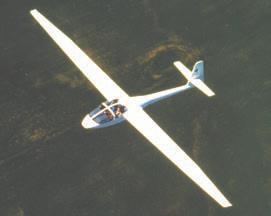
Induced drag is affected by the span-to-chord ratio, known as the aspect ratio. Wings with a high aspect ratio (such as those on sailplanes) produce significantly less induced drag than short, stubby wings.
The Total Drag on an Airplane
Total drag is the total of all the drag forces. As we have seen, total drag has two components:
• parasite drag; and
• induced drag
If we combine the graphs of parasite and induced drag as they vary with airspeed, we end up with a graph that illustrates the variation of total drag with airspeed (for a given airplane in level flight at a particular weight, configuration, and altitude). This total drag graph (figure 1-45) of drag versus airspeed (angle of attack) illustrates an extremely important relationship. It is a summary of all we need to know about drag.
Figure 1-43 Induced drag is greatest at low speeds and high angles of
versus airspeed.
Figure
Figure 1-44
High aspect ratio.
Wings of low aspect ratio
Wings of high aspect ratio
Chord Span
Figure 1-46 Aspect ratio.
The parasite drag increases with speed. The induced drag decreases as the speed increases. The graph shows how induced drag is predominant at low speed, while at high speed the parasite drag predominates. The total drag is least at the point where the parasite drag and the induced drag are equal. Many aspects of airplane performance are related to this minimum drag speed.
CPL
Drag from an Airfoil
At low speeds the total drag from the airfoil is high (because of induced drag) and at high speeds the total drag is high (because of parasite drag). A formula (similar to that for lift) can be developed for the drag produced by an airfoil:
Where:
• coefficient of drag (CD) represents shape and angle of attack;
• ½ ρV2 is dynamic pressure; and •S is the size of the object.
A drag curve for the airfoil relating CD to angle of attack can be developed. This is useful for comparison with the lift curve (CL versus angle of attack). Note that at high angles of attack near the stall angle, the coefficient of drag for an airfoil is high and is a large factor in the formula:
Figure 1-48
Coefficient of drag versus angle of attack.
At low angles of attack, as during normal cruise, the coefficient of drag for the airfoil is small, but the airspeed (V) is high, which has a large effect in the formula. This is why the drag force (D) is high at both extremes of angle of attack (and airspeed). In between these extremes is an angle of attack (and airspeed) where the drag force is a minimum. The minimum CD for a typical airfoil occurs at a small positive angle of attack.