PLUMBING, ELECTRICITY, ACOUSTICS
Sustainable Design
Methods for Architecture
Norbert Lechner
John Wiley & Sons, Inc.
This book is printed on acid-free paper. ∞
Copyright © 2012 by John Wiley & Sons, Inc. All rights reserved.
Published by John Wiley & Sons, Inc., Hoboken, New Jersey. Published simultaneously in Canada.
No part of this publication may be reproduced, stored in a retrieval system, or transmitted in any form or by any means, electronic, mechanical, photocopying, recording, scanning, or otherwise, except as permitted under Section 107 or 108 of the 1976 United States Copyright Act, without either the prior written permission of the Publisher, or authorization through payment of the appropriate per-copy fee to the Copyright Clearance Center, Inc., 222 Rosewood Drive, Danvers, MA 01923, 978-750-8400, fax 978-646-8600, or on the web at www.copyright.com. Requests to the Publisher for permission should be addressed to the Permissions Department, John Wiley & Sons, Inc., 111 River Street, Hoboken, NJ 07030, 201-748-6011, fax 201-748-6008, or online at http://www.wiley.com/go/permissions
Limit of Liability/Disclaimer of Warranty: While the publisher and author have used their best efforts in preparing this book, they make no representations or warranties with respect to the accuracy or completeness of the contents of this book and specifically disclaim any implied warranties of merchantability or fitness for a particular purpose. No warranty may be created or extended by sales representatives or written sales materials. The advice and strategies contained herein may not be suitable for your situation. You should consult with a professional where appropriate. Neither the publisher nor author shall be liable for any loss of profit or any other commercial damages, including but not limited to special, incidental, consequential, or other damages.
For general information on our other products and services, or technical support, please contact our Customer Care Department within the United States at 800-762-2974, outside the United States at 317-572-3993 or fax 317-572-4002.
Wiley publishes in a variety of print and electronic formats and by print-ondemand. Some material included with standard print versions of this book may not be included in e-books or in print-on-demand. If this book refers to media such as a CD or DVD that is not included in the version you purchased, you may download this material at http://booksupport.wiley.com. For more information about Wiley products, visit www.wiley.com
Library of Congress Cataloging-in-Publication Data:
Lechner, Norbert.
Plumbing, electricity, acoustics : sustainable design methods for architecture/Norbert Lechner. p. cm.
Includes index.
ISBN 978-1-118-01475-2 (cloth); 978-1-118-13010-0 (ebk.); 978-1-118-13011-7 (ebk.); 978-1-118-13108-4 (ebk.); 978-1-118-13109-1 (ebk.); 978-1-118-13110-7 (ebk.)
1. Buildings–Environmental engineering. 2. Buildings–Electric equipment–Design and construction. 3. Sustainable buildings–Design and construction. I. Title.
TH6031.L43 2011 696–dc23
ISBN 978-1-118-01475-2
Printed in the United States of America
10 9 8 7 6 5 4 3 2 1
2011018345
PREFACE ix
ACKNOWLEDGMENTS xi
1
ELECTRICITY – BASIC CONCEPTS 1
1.1 Introduction 2
1.2. History of Electricity 2
1.3 The Water Analogy 4
1.4 Ohm’s Law 6
1.5 Types of Electricity 6
1.6 Power Factor 9
1.7 Types of Circuits 11
1.8 Power Generators in Series and Parallel 15
1.9 Voltage Drop 16
1.10 Electrical Power 18
1.11 Electrical Energy 19
1.12 Paying for Electricity 20
1.13 Reduction in Maximum Demand 22
1.14 Transformers 23
1.15 Electricity and Safety 24
1.16 Electromagnetic Fields (EMF) 26
1.17 Conclusion 26 Resources 26
2
ELECTRICAL DISTRIBUTION IN BUILDINGS 27
2.1 Introduction 28
2.2 A Brief Historical Perspective 28
2.3 Centralized Electrical Power 30
2.4 Decentralized and Private Sources of Electricity 31
2.5 Electrical Distribution in Small Buildings 32
2.6 Electrical Distribution in Large Buildings 36
2.7 Switches, Fuses, and Circuit Breakers 39
2.8 Conductors 40
2.9 Conduits and Raceways 42
2.10 Office Landscapes 43
2.11 Electrical Safety Systems 47
2.12 Low-Voltage Circuits 50
2.13 Emergency Power 51
2.14 Communication and Building Control Wiring 53
2.15 Electrical Construction Drawings 56
2.16 Lightning Protection 56
2.17 Sustainability 58
2.18 Conclusion 59 Resources 59 3
PLUMBING—WATER SUPPLY
3.1 Introduction 62 3.2 Brief History of Water Supply 63
3.3 Sources of Drinking Water 64
3.4 Water Use 67
3.5 Private Water Supply 68
3.6 Rainwater Harvesting 71 3.7 Water Distribution in Buildings 79 3.8 Water Quality 85 3.9 Water Efficiency 85 3.10 Hot Water 88 3.11 Hot Water Conservation 97 3.12 Conclusion 103 Resources 103
61
4 DRAINAGE 105
4.1 Introduction 106 4.2 Short History of Sanitary Drainage 106 4.3 Basic Principles of Drainage 114 4.4 Basic Concepts of Plumbing Fixtures 115 4.5 Drainage Piping 116
4.6 Water Closets and Alternatives 121
4.7 Composting Toilets 125
4.8 On-Site Septic Tank Systems 126 4.9 On-Site Aerobic Systems 128 4.10 Special and Innovative Treatment Systems 130 4.11 Constructed Wetlands 131 4.12 Biologic Machines 134 4.13 Graywater Systems 136
4.14 Alternative Community Sewage Systems 139
4.15 Stormwater 141
4.16 Special Drainage Systems 152
4.17 Case Study 153
4.18 Conclusion 155
Resources 155
ARCHITECTURAL ACOUSTICS 157
5.1 Introduction 158
5.2 A Short History of Architectural Acoustics 159
5.3 The Physics of Sounds 161
5.4 The Biology of Sounds 170
5.5 Perception of Sound 175
5.6 Sound and Health 179
5.7 Sound-Absorbing Materials 180
5.8 Applications of Sound-Absorbing Materials 182
5.9 Sound Transmission 188
5.10 Design for Low Sound Transmission 189
5.11 Acceptable Noise Levels 194
5.12 Open-Plan Offices 196
5.13 Impact Noise 198
5.14 Mechanical Systems Noise Control 199
5.15 Theaters, Classrooms and Auditoriums 202
5.16 Rules for Drawing Ray Diagrams 205
5.17 Electronic Sound Systems 206
5.18 Noise Outdoors 206
5.19 Conclusion 210
Resources 211
FIRE PROTECTION 213
6.1 Introduction 214
6.2 A Short History of Fires in Buildings 216
6.3 Fire Principles 221
6.4 Fire Prevention 224
6.5 Passive Fire Protection 225
6.6 Detection 228
6.7 Alarms 229
6.8 Safe Egress 232
6.9 Fire Suppression 235
6.10 Non-Water Fire Suppression Systems 242
6.11 Smoke Control 243
6.12 Fire Codes 249
6.13 Elevators and Fires 250
6.14 Lightning Protection 250
6.15 Conclusion 251
CONVEYANCE SYSTEMS IN BUILDINGS 253
7.1 Introduction 254
7.2 A Short History of the Elevator 254
7.3 Elevator Types 261
7.4 Elevator Design 265
7.5 Escalators 271
7.6 Moving Walkways and Ramps 275
7.7 Vertical Transport and Health 276
7.8 Special Lifts for People 280
7.9 Material Conveying Systems 282
7.10 Conclusion 284 Resources 284
INDEX 285
PREFACE
“We should all be concerned about the future because we have to spend the rest of our lives there.”
Francis Kettering
“What is the use of a house if you haven’t got a tolerable planet to put it on?”
Henry David Thoreau
Plumbing, Electricity, Acoustics: Sustainable Design Methods for Architecture is a companion book to Heating, Cooling, Lighting: Sustainable Design Methods for Architects, because the two books together cover all or most of the topics in the field of environmental control. Although not mentioned in the title, this book also covers fire protection and building conveyance systems.
Although practicing architects and students of architecture are the primary audience of this book, it is also valuable for others in the building field. For engineers and contractors, this book can provide either an introduction to the subjects that are covered or an overview of topics related to their specialty. This book can also be useful to developers, building managers, homeowners, prospective building owners, and stakeholders who want to be involved in the design of their building.
This book emphasizes the concepts and facts needed at the schematic design stage, since that is where most of the important decisions are made for both the initial and long-term success of a building. Designers need to know not only what is required but also what options are available to them. Consequently, alternative strategies are presented where appropriate. This book also aids designers in making some of the more important decisions that will have to be made after the schematic design stage. Even the areas that are seen as the domain of engineers and consultants must be integrated into the design of the building at all stages. Since the architect is responsible for the success of the whole building, he or she must understand what the engineers and consultants are suggesting, and the architect must understand how these recommendations will impact the whole building.
The topic of electricity is covered in two chapters. Chapter 1 explains the basic concepts of electricity, while Chapter 2 explains how electricity is distributed throughout a building. Chapter 3 describes how potable water is obtained and distributed to the various plumbing fixtures in a building. Chapter 4 discusses plumbing fixtures and how they are drained. It also explains how to treat sewage and wastewater if a public sewer is not available, and it covers rainwater management. Chapter 5 presents architectural acoustics, and Chapter 6 covers fire protection in buildings. Finally, Chapter 7 discusses building conveyance systems with an emphasis on the people-moving systems.
In all chapters where it is appropriate, there is an emphasis on sustainability. It must be emphasized that sustainability will be achieved primarily through the elimination of waste (e.g., efficiency) and only partly through clean renewable energy. For example, zero-energy buildings result when the energy consumption is reduced about 80 percent because it is then practical for renewable energy to supply the remaining 20 percent.
Unlike renewable energy, which is constantly being supplied to the earth from the sun, no new water is being added to the planet. Furthermore, the usable fresh water, which is less than 1 percent of the total, has to meet the needs of a growing population of increasing affluence. Consequently, only greater efficiency will provide enough water for each person. Efficiency includes not only using less water for each activity but also making use of water normally discarded such as rainwater and wastewater.
Guidelines and rules of thumb are provided to help designers make their buildings use less energy, less water, and less of everything else, while making buildings achieve their primary objectives. Electrical energy can be saved not only by means of more efficient lighting fixtures and electrical appliances but also by turning these devices off when not needed. Manual and, increasingly, automatic switches and control systems are used because they take the bother out of turning things off. Saving water not only saves an increasingly limited resource but also saves the energy required to supply the water. In some situations, enormous amounts of energy are required, as in arid southern California, where fresh water is pumped over a mountain range and seawater is desalinated. Well-planned treatment of the effluent from a building’s drain system not only protects against potential health hazards but can also be a valuable source of reclaimed water and fertilizer. Building conveyance systems can utilize very efficient types of elevators and escalators, while architectural design can discourage the excessive use of elevators and escalators in situations where most people could walk a ramp or climb stairs. Green buildings are not only more sustainable but they can be healthier and more desirable places to live, work, and visit.
Because the United States is converting extremely slowly to the SI (Systeme Internationale d’Unites) system, both the old English and the SI units are given. (England switched to SI long ago.) To speed up the transition to SI, it is the policy of the federal government to use SI units on all of its projects, especially its building projects. In this book, the English “inch-pound” units are given first followed by the SI units in parentheses.
Now, in the twenty-first century, the implications of Henry David Thoreau’s words, uttered nearly 200 years ago, ring truer than ever. We must consider the environment when we build and construct buildings.
BASIC CONCEPTS
“I am an expert of electricity. My father occupied the chair of applied electricity at the state prison.”
—W. C. Fields (first half of the twentieth century)
“It is the triumph of civilization that at last communities have obtained such a mastery over natural laws that they drive and control them. The winds, the water, electricity, all aliens that in their wild form were dangerous, are now controlled by human will, and are made useful servants.”
—Henry Ward Beecher (mid-nineteenth century)
“We’ve arranged a civilization in which most crucial elements profoundly depend on science and technology.”
—Dr. Carl Sagan (second half of the twentieth century)
1.1 INTRODUCTION
Electrical power and its applications so completely pervade our lives that it is hard to imagine that a little over 100 years ago electricity in homes and businesses was a novelty about which architects did not have to concern themselves. As Carl Sagan’s quote implies, today we are fully dependent on electrical power. It is not surprising that the architecture of a building can be significantly affected by the need to supply power to lights and appliances. Although the architect rarely designs the electrical system, space must be allocated to transformer vaults and electrical closets. When supplying power to an open-plan office, the architect must understand the options in power and communication distribution systems since they can have major aesthetic consequences. For example, using power poles in an open plan office may be efficient but not desirable from an aesthetic point of view.
Specifying appliances and lighting fixtures sometimes requires an understanding of electricity. For example, some lighting fixtures are available in both 277V and 120V versions, and some appliances are available in both 120V and 240V. On what basis does one choose? Some appliances have a poor power factor. What does that mean, and what are the consequences? Should the building use one-phase or three-phase power? What is the difference?
Since many fires are caused by electrical failures, understanding electricity is also important for the safety of buildings and their occupants. Electrocution, although rare, can be practically avoided by proper design and specifications. Understanding electricity provides the reader with personal safety as well. For example, electrical shock can usually be prevented by the use of a ground fault circuit interrupter. How does such a device function, and how should it be used?
And most important of all, buildings must become much more sustainable. Since buildings consume over 70 percent of all electricity in the United States, reducing the consumption of electricity by buildings is of the utmost importance.
Thus, for many reasons, it is important to have an understanding of the basic concepts of electricity.
1.2. HISTORY OF ELECTRICITY
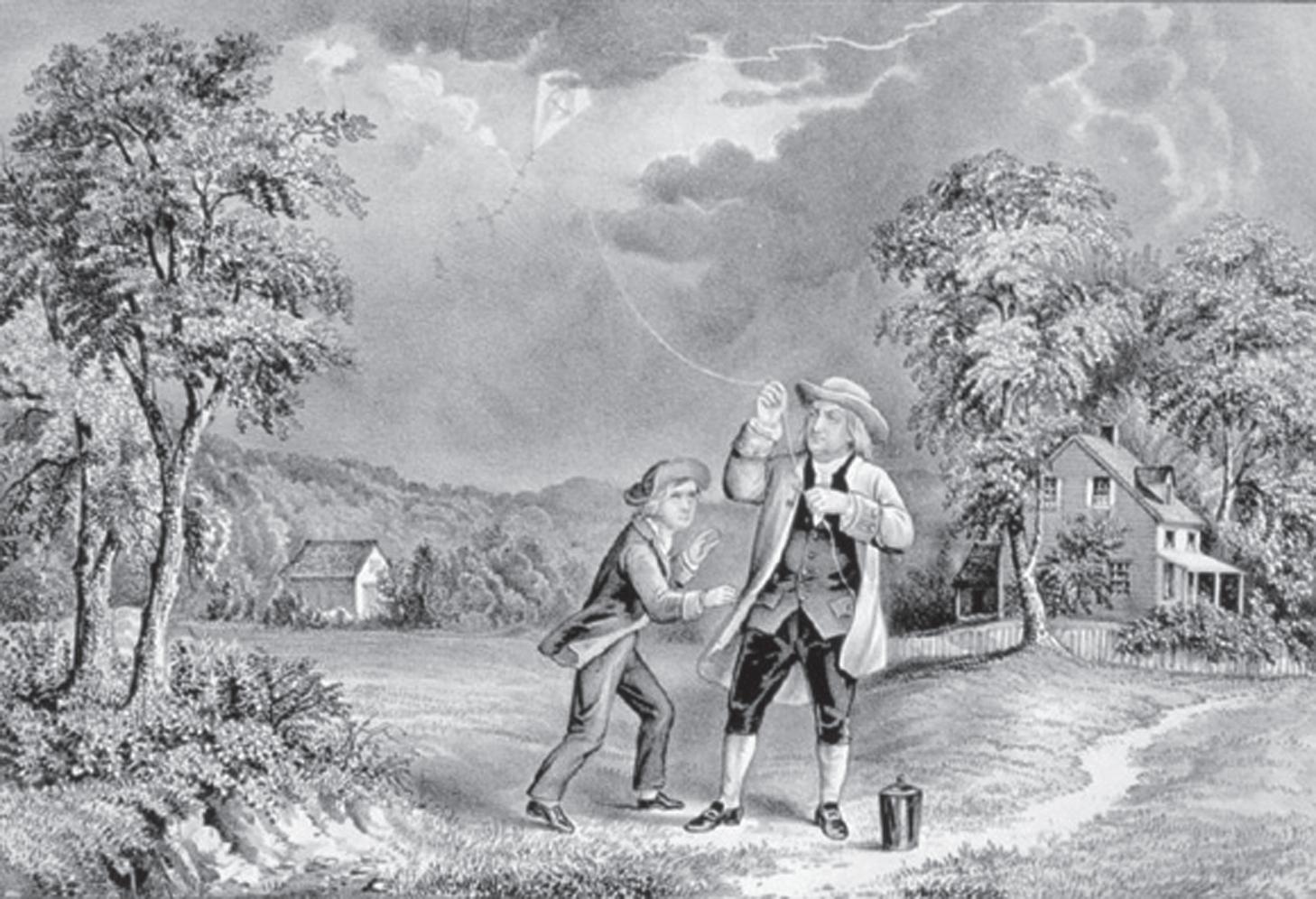
Static electricity was known to and described by the ancient Greeks around 600 BCE. Electricity was rediscovered during the Scientific Revolution of the sixteenth and seventeenth centuries. Investigation into electricity began in earnest in the seventeenth century, and by the middle of the eighteenth century, with the increased knowledge of its properties, Benjamin Franklin concluded that lightning must be made of electricity, which he proved with his famous kite and key experiment in 1752 (Fig. 1.2a). It was not only luck that prevented him from being electrocuted as were some other experimenters. He knew enough about electricity to take certain precautions, such as standing in a dry, sheltered location while flying his kite in a thunderstorm. He also knew that some materials were conductors (his wet kite string) and insulators (a dry silk ribbon by which he held the key). His understanding of electricity allowed him to invent the lightning rod for the purpose of protecting buildings.
The science of electricity developed rapidly after Alessandro Volta invented the battery in 1792, and thereby made available a steady flow (current) of electricity. Thereafter, the discovery of the relationship between magnetism and electricity made the development of electric motors, generators, and transformers possible. Besides Volta, some of the other scientists whose names have been immortalized by their adoption for use as names for electrical units are: Andre Ampere, George Ohm, and Heinrich Hertz. Although much was known about electricity, its composition remained a mystery until the end of the nineteenth century, when it was discovered that electricity is a stream (current) of electrons flowing from negative to positive charges.
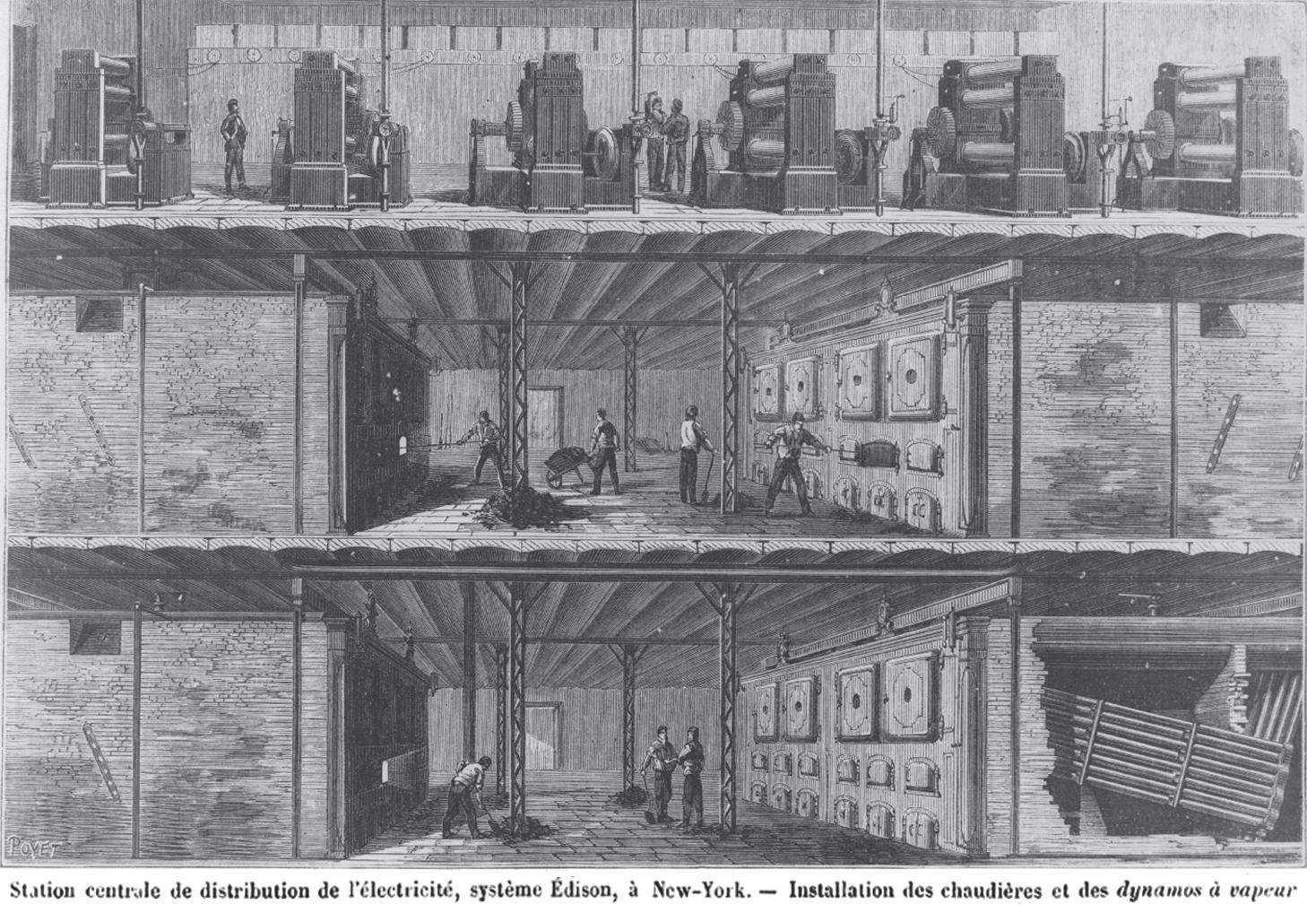
Thomas Edison put electricity to work. Until Edison perfected the electric lamp in 1879, all light sources came from open flames that created soot, heat, and often fire. Many had experimented with electric lighting, but Edison was the first to make it a practical reality. His creativity, versatility, and perseverance allowed him to succeed where many others had failed. To sell electric lamps, Edison had to also supply electricity, which required the invention of the electrical production and supply system. He opened his first direct-current central generating stations in both New York City (Fig. 1.2b) and London in 1882.
Of course, being an innovator, Edison also made mistakes. One of his biggest was to believe that direct current (dc) was better than alternating current (ac). Nicola Tesla, the great inventor and scientist, tried to convince Edison of the superiority of ac. Because he could not convince Edison, he sold his patents to George Westinghouse. Consequently, by the late nineteenth century, there were two competing electrical industries in the United States: Westinghouse for alternating current and Edison for direct current. To convince the public that his system was better, Edison claimed that dc was safer than ac because the electric chair used ac for executions. In reality, there is nothing inherently safer about dc.
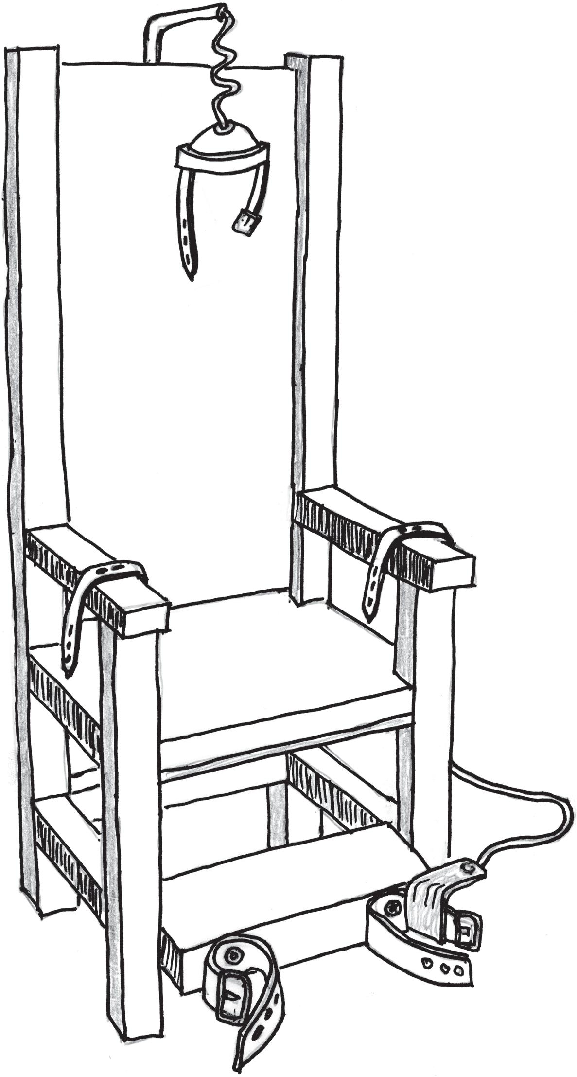
The electric chair was developed in 1890 because it was considered more humane than hanging. However, it has now been almost completely replaced by lethal injection. In the electric chair, a high voltage (about 2,000 volts) is used to drive about 5 amperes of current through the body
Fig. 1.2a Benjamin Franklin was internationally recognized for his research on electricity, and through his work, he invented the much needed lightning rod. Do not try his kite experiment at home! Other researchers trying this experiment died. Franklin took more precautions than this fanciful artwork shows. He was also lucky lightning did not strike his kite.
Source: Currier & Ives, Prints and Photographs Division of the Library of Congress.
Fig. 1.2b This cut-away drawing shows Edison’s 1882 Pearl Street Electric Power Station in New York City. The bottom two floors illustrate the coal-fired boilers, and the top floor shows a series of steamengine-driven generators.
Source: U.S. Department of Interior, National Park Service, Edison National Historic Site.
Fig. 1.2c The electric chair did not turn out to be as humane as its promoters believed. The intent of the skull cap was to direct electricity through the brain in order to destroy it first to eliminate pain.
(Fig. 1.2c). Metal head and leg bands are used to create a low resistance path through the whole body. Although most people die within a few minutes, some have survived more than 20 minutes. Electrocution is actually a high-tech version of burning someone at the stake. In the old days, people were burnt from outside in and now we can burn them from the inside out because electric currents always generate heat
The reason that Edison was wrong in promoting dc over ac will become clear later.
1.3 THE WATER ANALOGY
Because water is similar to electricity in many ways, and because we all have a very good understanding of the behavior of water, it makes a great analogy for many aspects of electricity. The scientists who named some of the properties of electricity understood this when they used the word current to describe the flow of electrons. Since all analogies have limits, we will only use the water analogy where it is helpful.
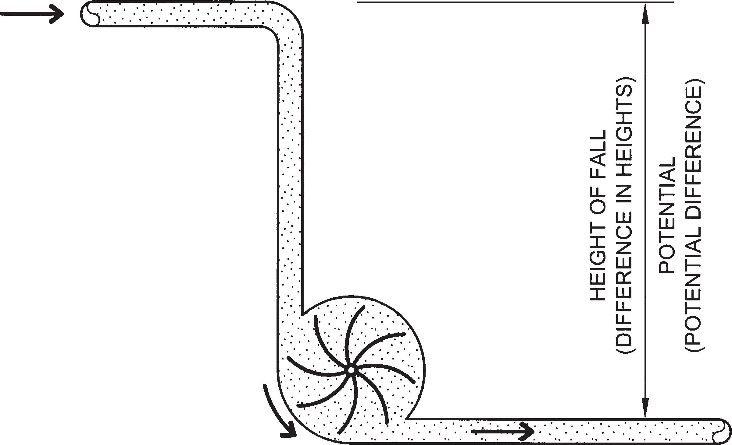
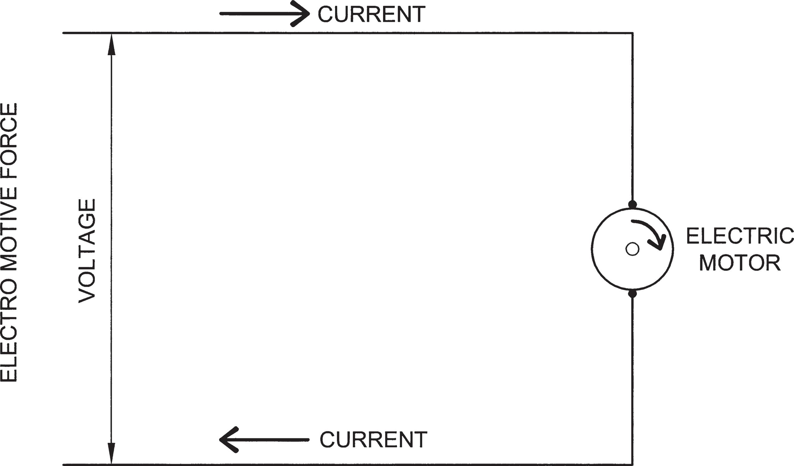
When people built water wheels, they understood that they would get the most power if the water fell from a great height and there was a large flow (current). In Figure 1.3a, you can see that the pressure (potential) powering the water wheel is a function of the height from which the water falls. However, the power output of the water wheel is also a function of the amount of water falling on it. Similarly, the output of an electric motor is a function of the electrical pressure, called the electromotive force, imposed on it and the electric current flowing through it (Fig. 1.3b). Electrical pressure results from a difference of electrical charges. Electrons will flow from a negative charge to a positive charge, and the greater the difference in charges the greater the electromotive force (E) measured in volts ( V )*. The electrical current (I) is propelled
* In most cases the following terms are interchangeable: electromotive force, voltage, electrical potential, and potential difference. They are all measured in volts.
by the voltage and its units are amperes (amps or A ). The electrical current is also impeded by the electrical resistance (R) measured in ohms ( Ω ) (see Table 1.3).
The flow of water in Fig. 1.3a is opposed not only by the resistance of the pipes but also by the resisting force as the waterwheel does work. Similarly, the current through a motor is opposed not only by the resistance of the wires in the motor but also by the resisting forces of the motor doing work. The first of these two properties that opposes the flow of electricity is called electrical resistance and will be discussed now. The second property that opposes the current is called inductive reactance and will be discussed later.
Just as the function of the water wheel system was to deliver power , so the function of an electrical circuit is also to deliver power (i.e., watts). Furthermore, as the power produced by a water wheel is a function of both height and flow, so too the power output of an electric circuit is a function of both the electromotive force (voltage) and current (amperes).
Fig. 1.3a The power output of the waterwheel is a function of the magnitude of the flow (current) and the difference in height, which creates the pressure.
Fig. 1.3b The power output of the electric motor is a function of the magnitude of the electric current and the electromotive force (voltage).
Table
1.3 The key properties of electricity (units are the same for S.I. and the American System)
Electromotive force
Current
Resistance
1.4 OHM’S LAW
volts (V)
amperes (amps or A)
ohms (Ω)
The simple relationship between current, voltage, and resistance is called Ohm’s law. It states that the current is directly proportional to the voltage and inversely proportional to the resistance as stated in the following formula:
I E R =
where:
I is the current measured in amperes (A)
E is the electromotive force measured in volts (V)
R is the resistance measured in ohms (Ω)
For example: What is the current flowing through an incandescent lamp that is rated 120 volts and 240 ohms?
I E R V amps Answer == Ω = 120 240 05
1.5 TYPES OF ELECTRICITY
Static electricity, which is usually created by friction, creates very high voltages but, luckily, very low currents. Thus, when static electricity discharges, the resulting spark is extremely short lived and is harmless unless the tiny spark ignites a combustible gas.
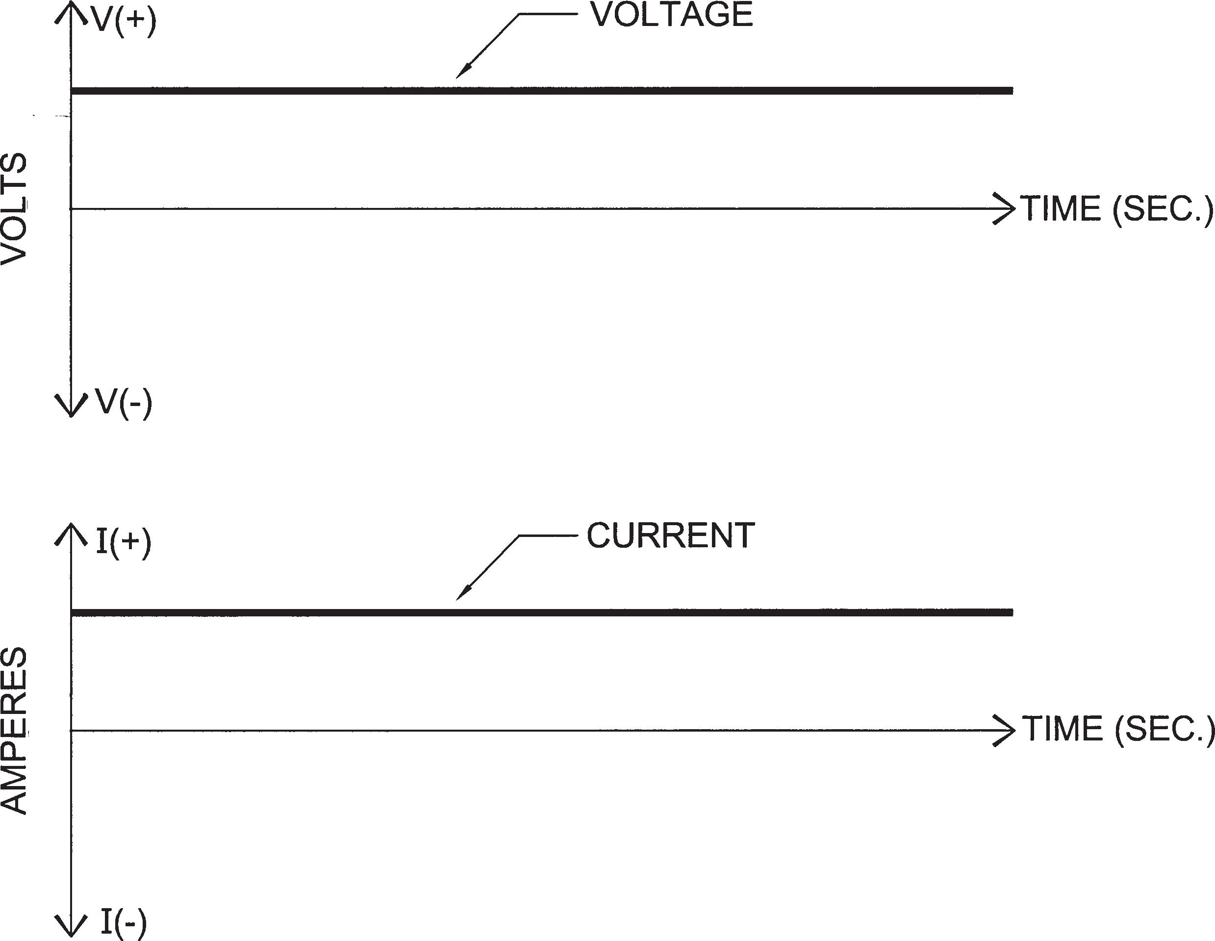
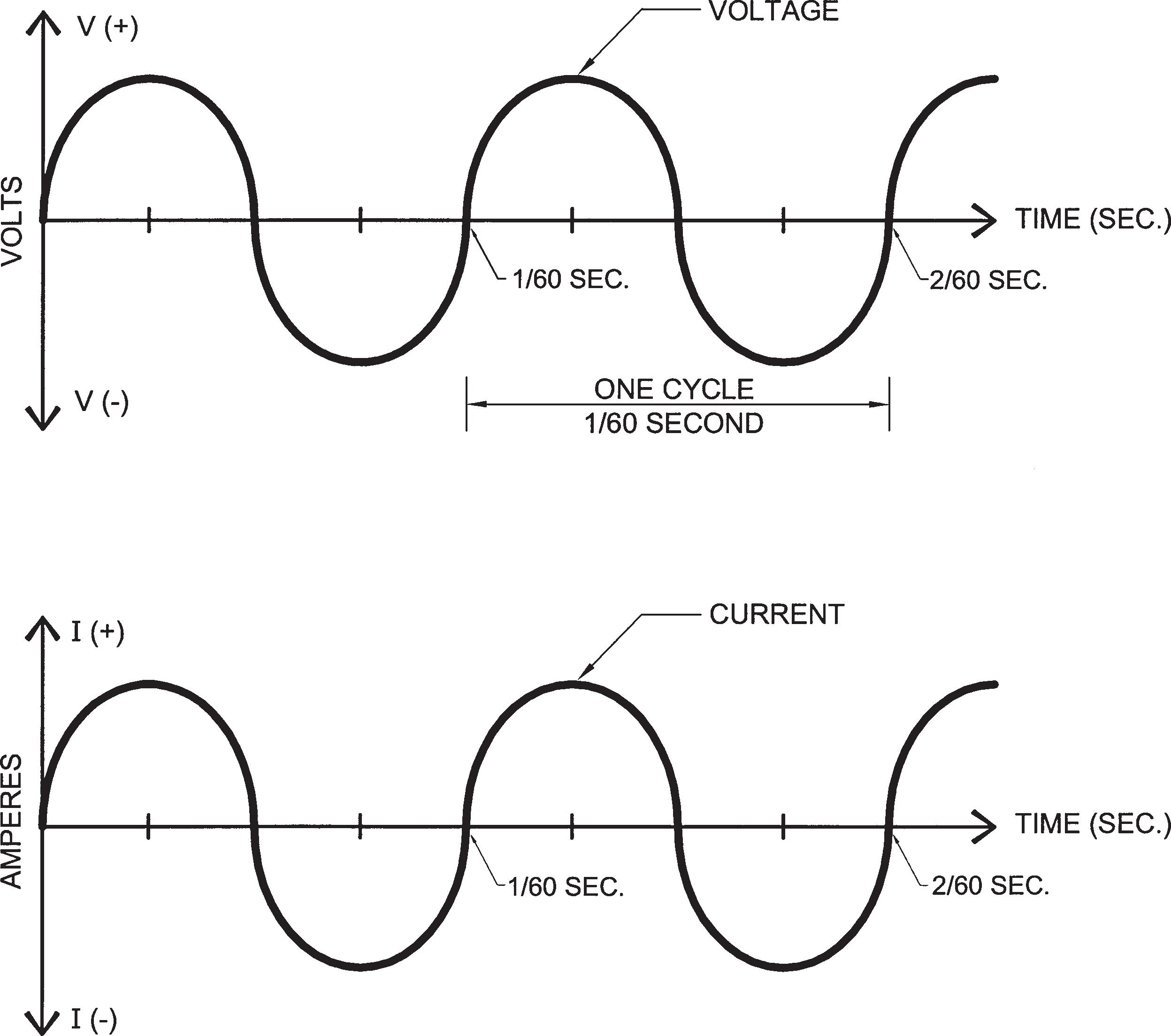
On the other hand, in normal electricity, the voltage and current are maintained over time. In direct current (dc), the voltage and current remain constant over time (Fig. 1.5a), while in alternating current (ac), the voltage and current change rhythmically over time (Fig. 1.5b). The rhythm is a sine curve because that is the natural outcome from generating electricity with a rotating generator. In the United States, each complete cycle of the sine curve is 1/60 sec long. Consequently there will be 60 such cycles per second (cps), and we call that a frequency of 60 hertz (Hz). Most of Europe and Asia, however, produce ac at a frequency of 50 Hz.
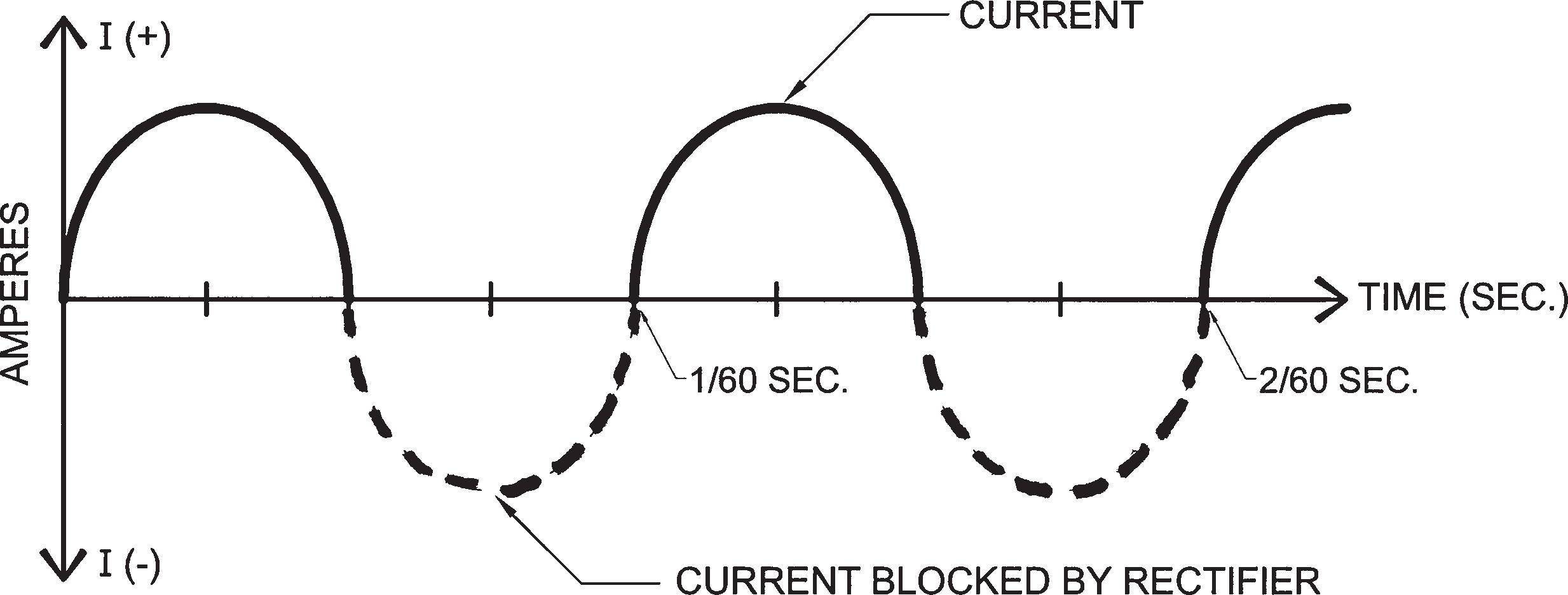
Almost all electricity used in buildings today is ac because it is so versatile. Its main virtue is that it can be easily changed from one voltage to another by means of a transformer. Nevertheless, there are still times when dc is required. The main application for dc in buildings today is for charging storage batteries for emergency power. This is similar to an automobile, where an alternator produces ac, but dc is needed to charge the battery that starts the engine. The ac is converted to pulsating dc by means of rectifiers or diodes, which are electrical devices that allow current to flow in only one direction (Fig. 1.5c).
Because most electronic devices, such as computers, run on lowvoltage dc, they have their own power supply, which converts the 120V ac line voltage to both dc and the required low voltage. In many electronic devices, the power supply is attached to the plug (Fig. 1.5d). Since electronic equipment, such as computers, are now a major electrical load in commercial buildings, there is increasing interest in providing low-voltage dc outlets along with 120V ac outlets. One of the benefits would be the elimination of all the wasteful power supplies that presently come with each electronic device. Another benefit would be the easy and efficient use
Fig. 1.5a These graphs show the voltage and current output from a battery. Because the voltage is constant and does not reverse (it stays above the horizontal axis), and since the current is driven by the voltage, it will likewise remain constant and will not reverse. Consequently, a battery produces direct current (dc).
Fig. 1.5b These graphs illustrate the behavior of alternating current (ac). The voltage changes in magnitude and direction (top graph), and since the current is driven by the voltage, it follows the same pattern (bottom graph).
Fig. 1.5c Because direct current is needed to charge batteries, the output of a car alternator which is ac is rectified to create pulsating dc.
of native power sources, such as solar, wind, fuel cells, and batteries, all of which supply dc. Converting these dc sources first into ac and then back into dc is a significant waste of money and energy. It is important to understand some of the consequences of supplying ac electricity at 60 Hz. An electrical cycle can be described by time (e.g., 1/60 second per cycle or 1/120 second per half-cycle) or in degrees (e.g., 360° per cycle or 180° per half-cycle). In a normal ac cycle, the voltage varies from zero at the start to a positive maximum at 90°, to zero at 180° to a negative maximum at 270°, and back to zero at 360°, which is also the start of the next cycle (Fig. 1.5e top graph). Consequently, the voltage
Fig. 1.5d Many electronic devices have their small power supply attached to the plug. The power supplies contain a stepdown transformer and rectifier to create low-voltage dc.
Fig. 1.5e In the normal electric service, which is also called one-phase power, there are two times each cycle when no power is delivered (see top graph). Three-phase power can deliver more power at the same voltage, because it consists of three separate ac currents that are 120° out of phase of each other. Consequently, there is never a time when current is not flowing through the motor.
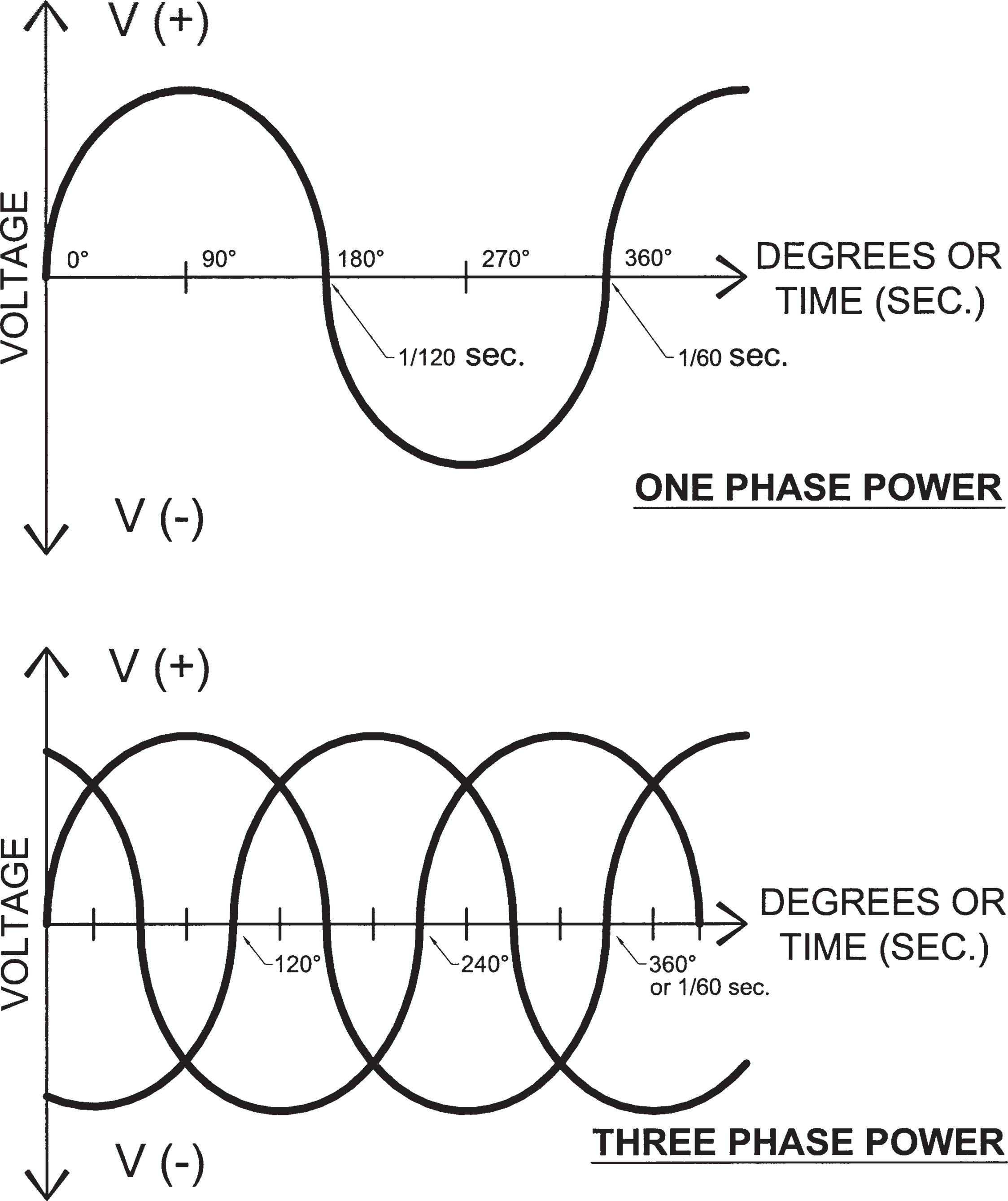
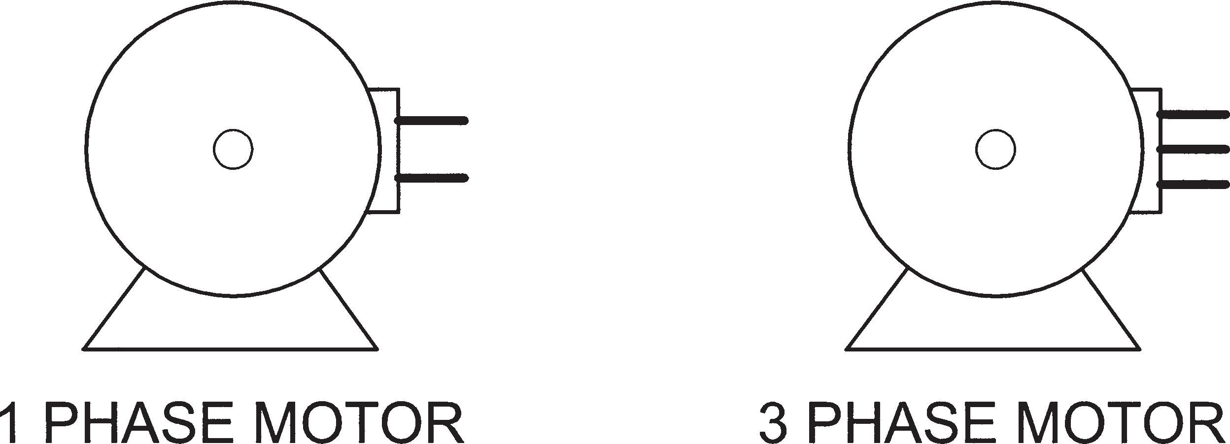
is zero twice each cycle, or 120 times each second (i.e., 2 times 60 Hz). And, of course, if there is no voltage, there is no current, or power being transmitted. Thus, electric motors receive 120 electric pushes per second, and old-style fluorescent lamps flashed 120 times each second. It is no wonder that Thomas Edison was convinced that dc is more efficient than ac; however, the benefits of ac greatly outnumber the disadvantages. The fact that in ordinary ac there is no current 120 times a second is in most cases not a problem. For example, our eyes see 120 flashes per second as a smooth continuous light. The ac pulses are only a problem for large motors that consume a lot of power. For such motors, three-phase power is available that consists of three separate ac currents 120° apart or, in other words, 120° out of phase (360° ÷ 3 = 120°) with each other. As can be seen in Fig. 1.5e (bottom graph), there is never a time when current is not flowing in at least two of the three phases. Three-phase motors are made differently from onephase motors and the two types cannot be interchanged (Fig. 1.5f).
1.6 POWER FACTOR
The formula of Ohm’s law (I = E/R) is only valid for circuits that supply power to devices that operate purely by electrical resistance (e.g., incandescent lamps and resistance heating elements). Almost all other electrical devices, such as motors and ballasts in lighting fixtures, use a magnetic field and are called inductors. These devices create an opposition to the flow of the current called inductive reactance, which together with the resistance is called impedance (Z), also measured in ohms. Thus, in most ac circuits, Ohm’s law states that the current is directly proportional to the voltage and inversely proportional to the impedance, as stated in the following formula:
where
I = current (amps)
E = electromotive force (volts)
Z = impedance (ohms)
Because magnetic coils (inductors) throw the current out of phase with the voltage, the power in a circuit is reduced. The negative impact of this phenomenon is often described by the power factor (PF), which is a number between zero and one, where one is the ideal. The power factor
Fig. 1.5f Three-phase motors need to have three electrical connections, whereas a normal (one-phase) motor needs only a twowire connection. Grounding wires are not included here and will be explained later.
Fig. 1.6 Any electrical device (e.g., electric motor) that has a coil of wire will operate by creating a strong magnetic field. Electrical coils, which are also called inductors, throw the current out of phase with the voltage, which is a problem for both the consumer and the power company. Fortunately, by adding capacitors this problem can be corrected (a small and a large capacitor are shown top and right). In a relay (lower left), a magnetic coil in one circuit operates switches in another circuit. In a solenoid (middle left), a magnetic coil moves a plunger to operate some mechanical device such as in a washing machine as it goes through its different operations.
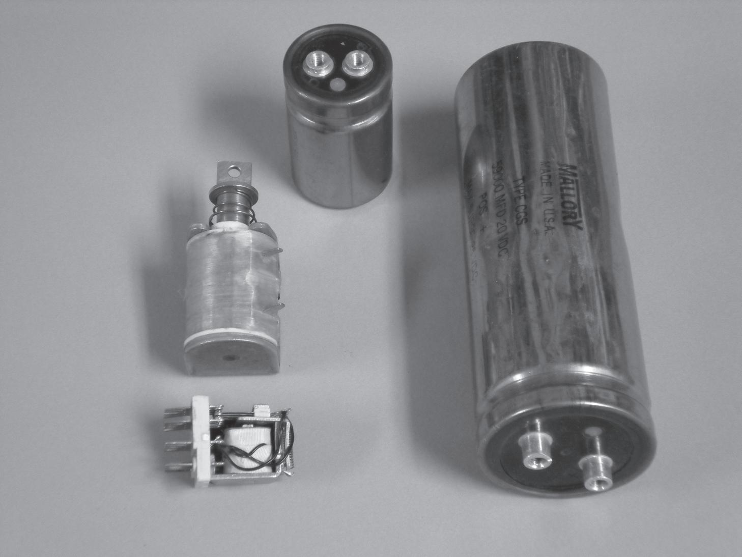
affects both the consumer and producer of electricity. Fortunately, electrical devices called capacitors (condensers) can correct this problem (Fig. 1.6). Consequently, many higher-quality electrical devices, such as motors and ballasts, have capacitors added at the factory to give them a high power factor. If too many electrical appliances are specified that have a low power factor, then the electric utility will apply a surcharge to the electric bill because it then has to spend money to correct the problem. The relationship between resistance, inductance, and capacitance is explained further in Sidebox 1.6.
SIDEBOX 1.6
Impedence
Impedance is the vector addition of resistance, inductive reactance, and capacitive reactance. The following vector diagram represents a particular motor that has a capacitor attached to it.
INDUCTIVE REACTANCE
RESISTANCE (Continued )
CAPACITIVE REACTANCE
Since inductive and capacitive reactance are in line, they can be added algebraically. Thus, the resulting inductive reactance is smaller and the capacitive reactance is canceled out.
RESISTANCE
INDUCTIVE REACTANCE
CAPACITIVE REACTANCE
The impedance (Z) of the motor is then the resultant of the resistance and remaining inductive reactance.
IMPEDANCE
RESISTANCE
INDUCTIVE REACTANCE
Note that the impedance is larger than the resistance and not in line (i.e., out of phase) with the resistance (or current). Also note that without the capacitor the impedance would be both larger in magnitude and more out of phase. The ideal situation would be to use a larger capacitor so that the capacitive and inductive reactances would be equal but opposite. Then, the impedance would be the same as the resistance.
1.7 TYPES OF CIRCUITS
Electrical devices can be connected either in series or in parallel or both. To better understand the consequences of these arrangements, let us again use a water analogy. For example, in heavy equipment, hydraulic instead of electrical systems are often used to transmit power. One way to transmit power with water is shown in Fig. 1.7a.
If we wanted to power three hydraulic motors we could arrange them either in series (Fig. 1.7b) or in parallel (Fig. 1.7c). The power output of each of the motors in series will be much less than its normal rating for two related reasons: (1) each motor receives only 1/3 the pressure (potential), and (2) because the same water must flow through each motor and is resisted by each, the total water flowing down is also one-third of that in Fig. 1.7a. With the help of the water analogy of a series circuit, let us look at an electrical series circuit, as shown in Fig. 1.7d. In series circuits, the total resistance is equal to the sum of all the resistances.
Or:
RT = R1 + R2 + R3 +
Thus, in a series circuit, the more resistances the greater the total resistance.