Next-Generation Solar Cells
Principles and Materials
Yoon-Bong Hahn
Tahmineh Mahmoudi
Yousheng Wang
Published by Jenny Stanford Publishing Pte. Ltd.
101 Thomson Road
#06-01, United Square
Singapore 307591
Email: editorial@jennystanford.com
Web: www.jennystanford.com
British Library Cataloguing-in-Publication Data
A catalogue record for this book is available from the British Library.
Next-Generation Solar Cells: Principles and Materials
Copyright © 2024 by Jenny Stanford Publishing Pte. Ltd.
All rights reserved. This book, or parts thereof, may not be reproduced in any form or by any means, electronic or mechanical, including photocopying, recording or any information storage and retrieval system now known or to be invented, without written permission from the publisher.
For photocopying of material in this volume, please pay a copying fee through the Copyright Clearance Center, Inc., 222 Rosewood Drive, Danvers, MA 01923, USA. In this case permission to photocopy is not required from the publisher.
ISBN 978-981-4968-66-9 (Hardcover)
ISBN 978-1-003-37238-7 (eBook)
4.3.3
5. Organic Solar Cells
5.1
5.3
5.4
5.3.2
5.3.3 Polymer Solar Cells
5.3.4 All-Polymer Solar Cells
5.3.5 Ternary Polymer Solar Cells
5.3.6 Organic Tandem Solar Cells Charge Dynamics in Polymer Solar Cells
5.4.1 Charge Dynamics Measurements
5.4.1.1 Transient absorption spectroscopy
5.4.1.2 Transient photovoltage and photocurrent
5.5.2
5.5.1.1 Transparent conductive oxide (TCO) substrate
5.5.1.2 Working electrode
5.5.1.3 Dye (or photosensitizer)
5.5.1.4 Electrolyte
5.5.1.5 Counter electrode (CE)
6.1
6.2 6.1.4 Application of Quantum Dots
6.2.1 Quantum Dots Solar Cell
6.3 Configuration
6.2.2 Basic Operation Principles and Physical Mechanism Quantum Dot/Semiconductor Heterojunction Solar Cells
6.3.1 Schottky Junction Solar Cells 6.3.2
6.4.2
6.4.3 6.4.2.3
7. Organic–Inorganic Hybrid Solar Cells
7.1 Graphene-Based Hybrid Solar Cells
7.2 Polymer–Quantum Dot Hybrid Solar Cells
7.2.1 Material Aspects
7.2.2 Hybrid Bulk Heterojunction Solar Cells with Large Bandgap Nanocrystals
7.2.3 Hybrid Bulk Heterojunction Solar Cells with Low-Bandgap Nanocrystals
7.2.4 Limiting
7.2.5 Interfacial Engineering in 7.3 Polymer–QD Hybrid Solar Cells
7.3.2.1 Tuning of the work function of graphene
7.3.2.2 Electron-transport materials
8.1.3 All-Inorganic Perovskites Perovskite Composition Engineering
8.2.1 A-Site Doping
8.2.2 B-Site Doping
8.2.3 X-Site Doping
9. Structures, Transport Materials, and Deposition
9.1 Perovskite Solar Cell Configurations
9.2 Transport Materials for Perovskite Solar Cells
11.3 Lead-Free Perovskite Solar Cells 221
11.3.1 Limitations of Pb-Based Perovskite Materials 221
11.3.2 Tin-Based Perovskites 222
11.3.3 Germanium-Based Perovskites 227
11.3.4 Antimony- and Bismuth-Based Perovskites 227
11.3.5 Halide Double Perovskites 228
12. Composites-Based Efficient and Stable Perovskite Solar Cells with Interface Engineering
12.1 Organic Materials–Based Perovskite Composites
12.1.1 Small-Molecule-Based Perovskite
Composites
12.1.2 Polymer-Based Perovskite Composites
12.1.3 Ammonium-Based Perovskite
Composites
12.1.4 Low-Dimensional/Three-Dimensional Perovskite Composites
12.2 Inorganic Material–Based Perovskite Composites
12.2.1 Metal Oxide–Based Perovskite
Composites
12.2.2 Carbon-Based Perovskite Composites
12.2.3 Semitransparent PSCs with Metal Oxide–Based Composites
12.2.4 Other Inorganic Halides–Based Perovskite Composites
12.3 Stability Enhancement with Interface Engineering
12.3.1 Why Is Interface Engineering Needed?
12.3.2
12.3.3
12.3.4
12.3.5
12.3.6 Interface Engineering at Multi-Interface Locations
12.4 Composite-Based Charge-Transport Materials
12.4.1 Composite-Based Electron-Transport Layer 12.4.2 Composite-Based Hole-Transport Layer
13. Characterization of Solar Cell Materials and Devices 271
13.1 Spectroscopic Techniques
13.2 Chemical Analysis
13.2.1 Fourier Transform Infrared
(FTIR) Spectroscopy
13.2.2 X-ray Photoelectron Spectroscopy (XPS)
13.2.3 Energy-Dispersive X-ray Spectroscopy
13.3 Physical Analysis
13.3.1 Raman Spectroscopy
13.3.2 Photoluminescence (PL) Spectroscopy
13.3.3 UV–Vis Absorption Spectroscopy
13.3.4 Ultraviolet Photoelectron
Spectroscopy (UPS)
13.4 Structural Analysis
13.4.1 X-ray Diffraction Analysis
13.4.2 Electron Microscopy
13.4.2.1 Transmission electron
microscope (TEM)
13.4.2.2 Scanning electron microscope (SEM)
13.4.3 Atomic Force Microscopy (AFM)
Characterization of Photovoltaic Parameters
13.5.1 Current–Voltage Analysis
13.5.2Incident Photon-to-Current 290 Conversion Efficiency Analysis
13.5.3 Impedance Spectroscopy
13.5.4 Space-Charge-Limited Current
Preface
Building a sustainable energy system is one of the great challenges of our time that has prompted both academia and industry to seek alternative energy and renewable energy solutions. Recently, advanced materials and technologies for the next-generation solar cells have been exploited to develop economically viable, high-performance solar cells. This book addresses the principles and materials for the development of the next-generation solar cells for a sustainable global society. It will appeal to advanced undergraduate- and graduate-level students as well as researchers interested in next-generation solar cells.
The first two chapters review electromagnetic radiation (EMR) and the physics and properties of semiconductors. Understanding the fundamental properties of EMR is essential for the design and fabrication of photovoltaic energy devices. Semiconductor materials are the most important parts of a solar cell because the absorption of photons, generation of charge carriers, and separation of photogenerated charge carriers take place in semiconductor layers of photovoltaic cells. Thus, understanding the physics and properties of semiconductors is very important for designing the materials and photovoltaic cells.
Chapter 3 deals with the structures of solar cells as well as their working principles and limitations. It describes in detail the methods to improve power-conversion efficiency. Chapters 4 to 7 introduce the various generations of solar cells. These photovoltaic devices can be classified into three generations based on the key materials used and the level of commercial maturity of the PV technology. Thirdgeneration solar cells, such as organic solar cells, quantum dots solar cells, and organic–inorganic hybrid solar cells, are especially described in detail in Chapters 5, 6, and 7, respectively.
Chapters 8 to 12 focus on the emerging perovskite solar cells (PSCs). The advent of PSCs has paved the way for significant PV developments due to impressive power-conversion efficiency. The extraordinary high efficiency of PSCs is attributed to several predominant breakthroughs, such as optimization of perovskite
films with additives and innovative design of device configurations with ideal interfacial materials. Chapter 8 introduces properties of perovskite materials as well as structures and basic working principles of PSCs. Chapter 9 reviews cell configurations, transport materials, and fabrication processes of PSCs in detail.
Chapter 10 discusses defects and ions’ migration because the performance of PSCs is greatly affected by the quality of interfaces, crystallographic defects, and ions’ migration. Ions’ migration in perovskite layer is especially a major cause of anomalous device behaviors, including light-soaking effect, current-voltage hysteresis, and slow decay of open-circuit voltage in active layer.
Chapter 11 focuses on quantum dots, tandem, and lead-free PSCs. PSCs suffer from efficiency degradation and device instability due to deterioration of perovskite molecules when operating under harsh conditions for a long time. To solve such problems, quantum dot photovoltaics and tandem PSCs have been developed. Another critical problem with PSCs is lead (Pb) toxicity, which prevents commercial use of PSCs. To replace lead with non-toxic materials, the Pb-free absorbers should have low toxicity and proper stability.
Chapter 12 covers composite-based, efficient, and stable perovskite solar cells with interface engineering. Perovskite-based composites combined with metals, metal oxides, and graphene are effective in solving the performance degradation and instability problems in PSCs. The chapter also introduces interface engineering as an approach to resolve interfacial instability, resulting from the interaction between the perovskites and charge transport materials.
Chapter 13 introduces characterization techniques of solar cell materials and devices. To develop reliable and efficient cells and devices, the materials should be examined in term of chemical, physical, and structural analysis. In addition, photovoltaic parameters should be defined to evaluate device performance.
Last but not least, we would like to acknowledge the publishers and authors who kindly permitted reprint of their work, Jenny Stanford Publishing for carefully editing of this book, and all of our families. Especially, I, Yoon-Bong Hahn, would like to pay special thanks to my co-authors for their constant efforts and enthusiasm.
Yoon-Bong Hahn
Tahmineh Mahmoudi Yousheng Wang March 2023
Chapter 1
Electromagnetic Radiation
Understanding the fundamental properties of electromagnetic radiation (EMR) is essential for the design and fabrication of photovoltaic energy devices. EMR is the emission and transmission of energy in the form of electromagnetic waves, i.e., electric field and magnetic field components. EMR is made when atoms absorb energy. The absorbed energy causes one or more electrons to change their position within an atom. When electrons return to their original position, electromagnetic waves are generated. Solar radiation, or sunlight, is the EMR emitted by the sun that can be captured and turned into various types of energy (e.g., heat and electricity) using energy devices. This chapter introduces the characteristics of EMR and the quantities that can be used to evaluate radiation and photon energy.
1.1 Light and Photon
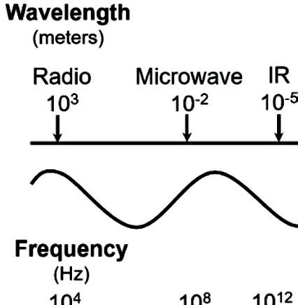
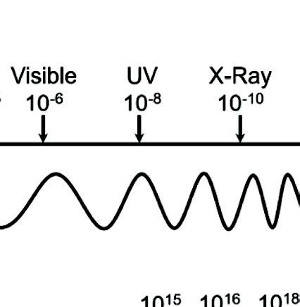
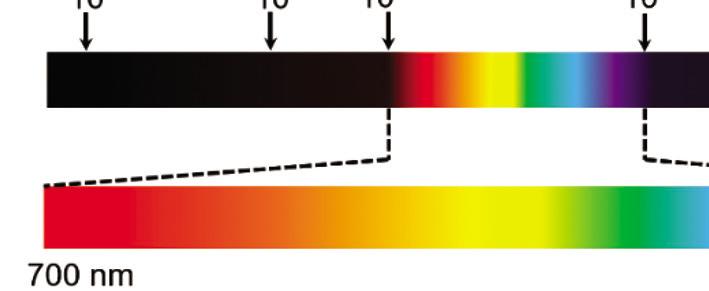
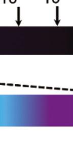
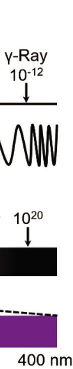
EMR travels through space at the speed of light in packets of radiant energy called photons, which contain neither mass nor charge. EMR can vary in strength from low energy to high energy, including radio waves, microwaves, infrared light, visible light, ultraviolet light, X-rays, and gamma rays. EMR is classified by wavelength (l)
Next-Generation Solar Cells: Principles and Materials
Yoon-Bong Hahn, Tahmineh Mahmoudi, and Yousheng Wang
Copyright © 2024 Jenny Stanford Publishing Pte. Ltd.
ISBN 978-981-4968-66-9 (Hardcover), 978-1-003-37238-7 (eBook) www.jennystanford.com
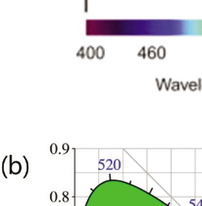
or frequency (n). Figure 1.1 illustrates the spectrum of EMR with visible light highlighted.
Figure 1.1 Spectrum of the electromagnetic radiation with visible light highlighted.
The optical region, which is the wavelength region responsible for light and solar energy conversion, consists of the infrared region (IR), the ultraviolet region (UV), and the visible-light region ranging in wavelengths from 400–700 nm. Wavelength and frequency hold the relationship [1]:
l n = c (1.1)
where c represents the speed of light (2.998 × 10⁸ m/s), which is a function of the refractive index of the medium (nr) through which the radiation travels.
Photon energy is calculated by:
E hc == hn l (1.2)
where h is Planck constant (h = 6.62607015 × 10⁻³⁴ J∙s).
The dimension of photon energy (E) is electronvolt (eV). It is worth noting that the bandgap of a solid (i.e., minimum energy required to promote an electron from the valence to the conduction band) and the wavelength of light that is reflected by the solid are related to one another by Eq. (1.2).
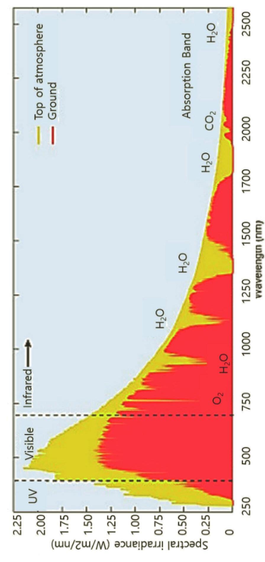
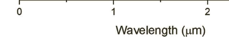
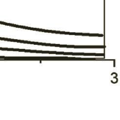
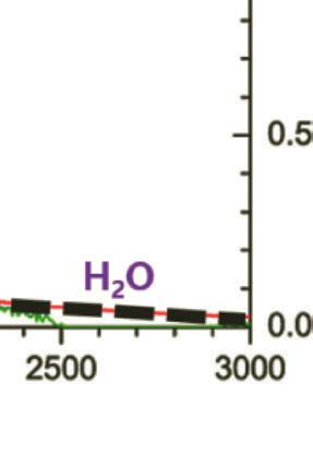
Figure 1.2 Solar spectral photon flux densities at the top of Earth’s atmosphere, at the Earth surfaces with estimated absorption of water, in vivo BChl pigment, carotenoids. BChla and BChlb and green sulfur bacteria. Reprinted with permission from Ref. [4], Copyright 2021, Elsevier.
The wavelength of photon energy emitting from a solid can be calculated using the following formula with the bandgap (Eg) of solid:
Through the atmosphere, light is influenced by gases, aerosols, and dust as they absorb photons with specific absorption bands. As sunlight reaches the atmosphere, most UVs (below 300 nm) get absorbed by ozone (O3) and most IRs (above 2 mm) are absorbed by atmospheric gases such as water vapor (H2O) and carbon dioxide (CO2) [2, 3]. Figure 1.2 shows the solar spectrum with several photons arriving at the atmosphere and Earth surfaces as a function of wavelength.
1.2 Photometry
Photometry is the science of measurement of light in a way that takes the sensitivity of human eyes. Contrary to radiometry, which measures light in wider wavelengths including UV and IR regions, photometry only measures in the visible spectral region (360 nm ~ 830 nm), where human eyes are sensitive. Human eyes are sensitive to three regions of frequencies, known as blue (~419 nm), green (~531 nm), and red (~558 nm). Observed colors are composed of a broad range of these three regions. The most dominant wavelength in a color is the color’s hue. The saturation of the color is the amount of distribution in wavelengths in the color. For example, a highly saturated color contains a narrow set of wavelengths [5].
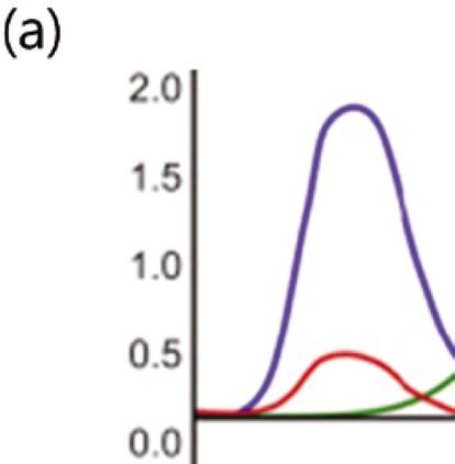
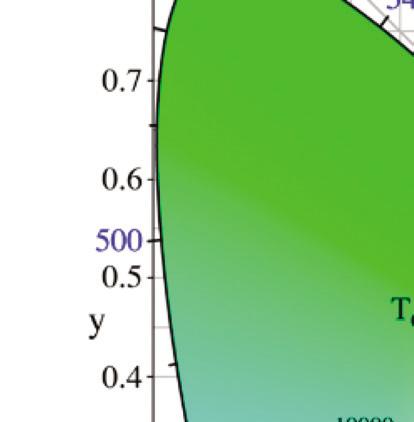
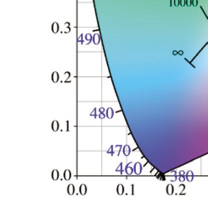
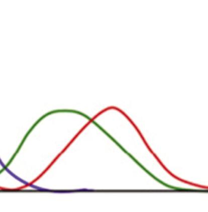
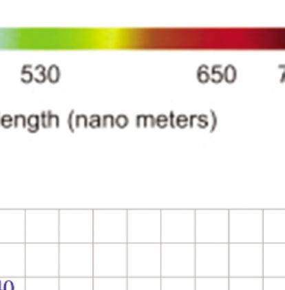
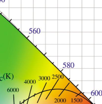
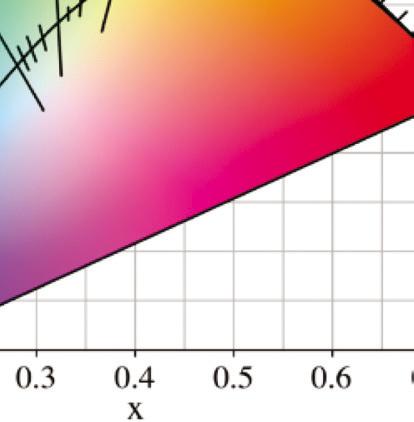
The concept of color by the human eyes is measurable by tristimulus values, which is the foundation of color language, and refers to the Commission Internationale de l’Éclairage (CIE) color system. Tristimulus values measure light intensity based on defined primary RGB (red-green-blue) color values, presented as X, Y, and Z coordinates, and can define precise color values around the world (Fig.1.3a).
A chromaticity diagram is a full plot of all visible colors sensible by average human eyes (Fig. 1.3b). The xy values indicate the contribution of the three primaries (RGB), and the boundaries indicate the highest saturation of spectral colors. In the chromaticity diagram, hot objects emit electromagnetic radiation at different
Figure 1.3 (a) The CIE standard observer color matching functions to map blackbody into XYZ coordinates. Reprinted with permission from [6], Copyright 2021, Elsevier. (b) The CIE 1931 color space chromaticity diagram. The Planckian locus is the path that a blackbody color emission through the diagram as the blackbody temperature rises.
ranges of frequency and wavelength. Hot body emission is called incandescence, which comes from the Latin verb incandescere,
meaning ‘to glow white.’ It specifically refers to the visible region, unlike thermal radiation which refers to IR or other electromagnetic radiation. For example, the white light of the tungsten filament bulb is equal to blackbody radiation at around 2900 K. Irradiating blackbodies in the chromaticity diagram form the Planckian locus. From low to very high temperatures, the emission of irradiating blackbodies changes from deep red to orange, yellowish-white, white, and bluish-white at the end [7–9].
1.3 Blackbody Radiation
All objects at a temperature above absolute zero (0 K, –273.15°C) emit energy in the form of EMR. A blackbody is a hypothetical object that completely absorbs all radiation energy, without reflecting, scattering, or transmitting it and reaches an equilibrium temperature, emitting all that energy quickly. Thus, a blackbody is a theoretical object which is a perfect absorber, and the emission of thermal energy radiated from the blackbody depends only on its temperature. The electromagnetic energy radiated from the surface of a hot object is called thermal radiation [10].
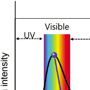
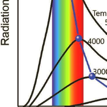
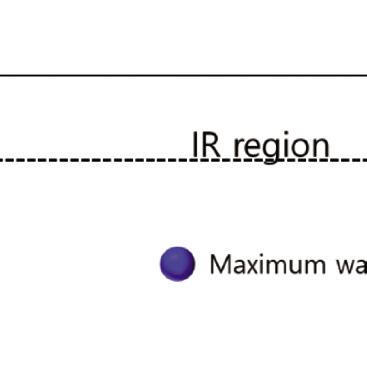
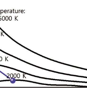
Figure 1.4 Blackbody radiation intensity curves as a function of wavelength and temperature.
The blackbody radiation at different temperatures is shown in Fig. 1.4. The features of blackbody can be explained by several laws:
■ Planck’s radiation law: Spectral-energy density of the emission (El) is a function of wavelength (l) and absolute temperature (T).
where h is Planck’s constant (h = 6.62607015×10⁻³⁴ J∙s), c is the speed of light, and k is Boltzmann constant (k = 1.38064852×10⁻²³ m2 kg s–2 K–1).
■ Wien’s displacement law: The blackbody radiation plot for different temperatures shows peaks at different wavelengths that are inversely proportional to the temperature.
■ Wien’s law: As the temperature of a blackbody increases, the peak wavelength decreases. The peak of the emission at all wavelengths increases as the temperature of the blackbody increases.
■ Stefan–Boltzmann law: The total energy being radiated (the area under the curve) increases rapidly as the temperature increases (E ~ T4). At any temperature above absolute zero energy is theoretically emitted at all wavelengths, but the blackbody radiation intensity curves never reach zero.
According to Wien’s displacement law, the spectral radiance of blackbody radiation per unit wavelength (i.e., the wavelength of emission peak) decreases as the temperature of the radiation object increases, given by:
where T is the absolute temperature and a is Wien’s displacement constant, equal to 2.9 × 10⁻³ m⋅K. Wien’s law states that the peak wavelength is inversely proportional to temperature but the peak frequency is directly proportional to temperature [11, 12]. When the temperature of an object rises, total radiation increases, and the emission peak shifts into the visible radiation range, causing the object starts to emit dark red and orange-red colors, and at very high temperatures the emission becomes white, as shown in the chromaticity diagram, Fig. 1.3.
Blackbody
1.4 Planck’s Radiation Law
Planck’s radiation law, formulated by Max Planck in 1900, is a mathematical equation to explain the spectral-energy distribution of emission by a blackbody. Planck assumed that the energy of oscillating atoms is the source of radiation. He further assumed that when an oscillating atom changes a state of energy E1 to a lower state of energy E2, a discrete amount of energy between two states (i.e., E1 – E2) is equal to the product of frequency (n) of radiation and a constant h (Planck’s constant). Then the blackbody radiation was determined by E1 – E2 = hn [9, 13–18, 20]. Planck’s radiation law for the energy radiated from a blackbody per unit volume in the wavelength interval Δl is given by Eq. (1.5).
The blackbody spectrum describes thermal radiation which is an essential concept for device engineering in physics and chemistry. For solar energy harvesting devices, in order to design photon energy-to-electricity devices, it is important to know the spectral distribution of solar irradiation, its intensity, and the amount of energy. In semiconductors, thermalized radiation is a useful tool to obtain transition rates for light absorption and emission.
1.5 Solar Spectrum
The solar spectrum covers wavelengths ranging from gamma rays to radio waves, as shown in Fig. 1.1. Solar radiation has irradiation energy as much as a blackbody radiator at around 5800 K.
As the solar radiation travels through the atmosphere, it is attenuated by absorption and scattering by active components in the atmosphere such as H2O, N2, O2, and CO2 (see Fig. 1.5). The absorption and scattering by active components in the atmosphere weakens the intensity of short-wavelength light and when sunlight reaches the Earth’s surface, the spectrum is severely narrowed between the far-IR and near-ultraviolet [21–26].
The optical path length through the atmosphere is determined by the air mass (AM) coefficient, which is defined as a ratio relative to the path length vertically upwards. The solar spectrum outside the atmosphere, approximated by the 5,800 K black body, is named
‘AM0,’ meaning air mass at ‘zero atmosphere.’ Solar cells used for space power applications, like those on communications satellites, are generally characterized using AM0.
The spectrum after passing through the atmosphere to sea level with the sun directly overhead is referred to ‘AM1,’ meaning air mass at ‘one atmosphere.’ Solar cell panels do not generally operate under exactly one atmosphere’s thickness: if the sun is at an angle to the Earth’s surface the effective thickness will be greater. Many of the world’s major population, solar installations, and industries lie in this area. Therefore, an AM number representing the spectrum at mid-latitudes is much more common, i.e., AM1.5 is used for midlatitudes, meaning 1.5 atmosphere thickness. AM1.5 corresponds to a solar zenith angle of 48.2°. The solar industry has been using AM1.5 for all standardized testing or rating of terrestrial solar cells or modules, including those used in concentrating systems.
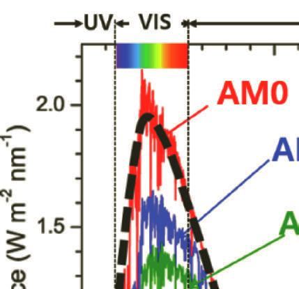
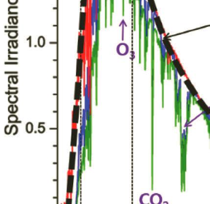
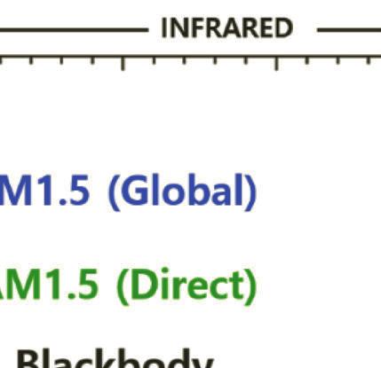
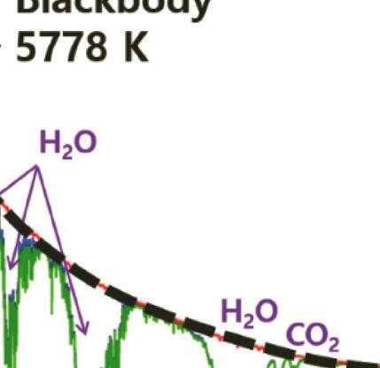
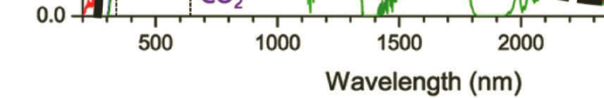
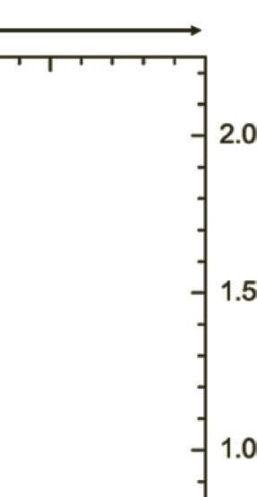
Figure 1.5 Standard solar irradiance spectrum in zero atmosphere AM0 (reference spectrum) and AM1.5. The dashed line refers to the blackbody at 5778 K.
Solar Spectrum
The reference spectrum of AM0 signifies the spectral of solar irradiance above the atmosphere. In 2000, the American Society for Testing and Materials established the reference spectrum of E490-00a (2019) as a standard solar constant for AM0 (zero air mass spectral irradiance). Furthermore, two reference spectra are included for the irradiance under absolute air mass of AM1.5G or Global spectrum (ASTM G173). AM1.5G is the spectrum that includes the blue sky and the surrounding ground. The integrated power of AM1.5G is 1000 W·m–2 with a photon flux of 4.31E21 S–1m–2. The standard AM1.5D or Direct spectrum—unlike AM1.5G—includes radiation coming only from small surroundings of the sun and projected orthogonally onto the cell. The difference between the AM1.5D and AM1.5G spectra is mainly the blue sky and light scattering in the atmosphere. The integrated power density of AM1.5 D is 900 W·m–2 [27–30].
References
1. Castrejón-García, R., Castrejón-Pita, J. R., Castrejón-Pita, A. A. (2010) Rev. Sci. Instrum., 81, pp. 055106.
2. Chen, Z., Zhu, L., Raman, A., and Fan, S. (2016) Nat. Commun., 7, pp. 13729.
3. Doscher, H., Young, J. L., Geisz, J. F., Turner, J. A., and Deutsch, T. G. (2016) Energy Environ. Sci., 9, pp. 74–80.
4. Cleveland, C. J. and Morris, C. G. (2013) Handbook of Energy: Chronologies, Top Ten Lists, and Word Clouds, Vol. 1, Elsevier.
5. Dyachenko, P. N., Molesky, S., Petrov, A. Y., Störmer, M., et al. (2016) Nature Communications, 7, pp. 11809.
6. Mark, N. and Aguado, A. (2019) Feature Extraction and Image Processing for Computer Vision. Academic Press.
7. Fowles, G. R. (1989) Introduction to Modern Optics. Dover: New York.
8. Howell, J. R., Siegel, R., and Menguc, M. P. (2010) Thermal Radiation Heat Transfer. CRC Press: New York.
9. Kangro, H. (1976) Early History of Planck’s Radiation Law. Taylor & Francis: London.
10. Kennard, E. H. (1918) Phys. Rev., 11, pp. 29–38.
11. Kiang, N. Y., Siefert, J., and Govindjee, B. (2007) Astrobiology, 7, pp. 222–251.
References
12. Landsberg, P. T. (1978) Thermodynamics and Statistical Mechanics Dover: New York.
13. MacIsaac, D., Kanner, G., and Anderson, G. (1999) Phys. Teach., 37, pp. 520–523.
14. Markvart, T. (2007) Appl. Phys. Lett., 91, pp. 064102.
15. Markvart, T. (2008) J. Opt. A, 10, pp. 015008.
16. Mooney, J. and Kambhampati, P. (2013) J. Phys. Chem. Lett., 4, pp. 3316–3318.
17. Murphy, A. B., Barnes, P. R. F., Randeniya, L. K., Plumb, I. C., et al. (2006) Int. J. Hydrog. Energy, 31, pp. 1999–2017.
18. Overduin, J. M. (2003) Am. J. Phys., 71, pp. 219–219.
19. Petty, G. W. (2006) Atmospheric Radiation, 2nd Ed. Sundog Publisher: Madison.
20. Planck, M. (1914) The Theory of Heat Radiation. P. Blakiston’s Son & Co: Philadelphia, PA.
21. Ries, H. and McEvoy, A. J. (1991) J. Photochem. Photobiol. A, 59, pp. 11–18.
22. Robitaille, P.-M. (2008) Prog. Phys., 3, pp. 36–55.
23. Ross, R. T. (1967) J. Chem. Phys., 46, pp. 4590–4593.
24. Shirasaki, Y., Supran, G. J., Bawendi, M. G., and Bulovic, V. (2012) Nat. Photonics, 7, pp. 13–23.
25. Sizmann, R., Köpke, P., Busen, R. (1991) Solar radiation conversion: In: Winter, C.-J., Sizmann, R. L., Vant-Hull, L. L. (eds.), Solar Power Plants. Fundamentals, Technology, Systems, Economics. Springer: Berlin.
26. Smestad, G. and Ries, H. (1992) Sol. Energy Mater. Sol. Cells, 25, pp. 51–71.
27. Waldman, G. (1983) Introduction to Light. Dover Publications: New York.
28. Würfel, P. (2009) Physics of Solar Cells. From Principles to New Concepts, 2nd Ed. Wiley: Weinheim.
29. Yablonovitch, E. (1982) J. Opt. Soc. Am. 72, pp. 899–907.
30. Zanetti, V. (1984) Am. J. Phys., 52, pp. 1127–1130.
Problems
1.1 Explain the relationship between wavelength, frequency, and photon energy.
1.2 The difference in energy between the valence band and the conduction band of solid material is called the ‘bandgap.’ What is the minimum wavelength in nm required to promote an electron from the valence to the conduction band of a semiconductor with a bandgap of 1.5 eV?
1.3 Explain Planck’s radiation law.
1.4 The solar spectrum intensity is defined by the AM parameter, briefly explain the AM parameter and the difference between AM1.5, AM1, and AM0.
1.5 If the absolute temperature of a black body is increased from T to 1.414T, by what factor is the total emitted power per unit area (RT) increased? (Use Stefan’s law.)
1.6 Light with wavelength of 525 nm is green. Calculate the energy in joules for green light photon.
1.7 What is the wavelength of light with frequency of 3.42 × 10¹¹ Hz?