CHAPTER II.
LOCATION AND CONSTRUCTION.
Location.
—Location is a moderate sized word with a vast meaning. It has two definitions as applied to meat packing houses.
First.
—Location as to a live stock supply. Pioneers in foreign lands looking for a cheap supply must take into consideration the quantity immediately available, the probabilities based upon feeding, climate, natural enemies—beast and bug—and the ambition of the people to produce as well as their ability to produce.
Sometimes an apparent supply is at hand but a searching investigation will show that it is an accumulated surplus, soon exhausted, with a resultant dearth. In the case of cattle, a supply cannot be created in a day but by persistent effort and in several generations of human life.
Transportation by trooping and by train, or the ability of the cattle to withstand the first or the ability of the railways to handle for want of facilities, are at times matters of much consequence.
Second.
—Location as applied to a position for operating, applicable to domestic or foreign works. There are several items of prime importance to be considered in selecting a location from this standpoint. In many instances a plant is established near a locality producing a sufficient quality of live stock suitable for a certain purpose, for example pigs suitable for export trade. In some instances the selection of a location is made for trade reasons, or to be adjacent to a stock yards; and in instances because property is
owned in a certain locality. Where situation can be of choice, the matters for most serious consideration are sewage disposal, water supply, prevailing winds and transportation facilities.
Water Supply.
—This is of great consequence. The quantity to be used for condensing purposes, refrigerating machinery operation, for cleansing, and in the regular course of business, is a very large amount, and if purchased from water supply corporations or municipalities, at prevailing rates, become a burdensome item of expense. The principal use for water can be classified under three headings:
BoilerPurposes
—This naturally will be selected from available sources based upon fitness, irrespective of cost.
Condensing
—First, for refrigerating machinery ammonia condensing and for steam engine condensing, in conjunction with the production of power and operating steam engines on refrigerating equipment. For this purpose cold water is desirable. If it can be obtained from wells it is the best practice, owing to such water usually being of low temperature. However, the cost of production must be considered, and that calls for engineering knowledge as to relative conditions. Usually, unless the surface water be in large quantity and available from a stream, the wells prove economical unless the water must be raised from great depths involving air lift pumping. There are instances, however, where turbidity makes water from streams undesirable and where well water is unobtainable, and in instances of this kind use of settling basins, reservoirs and cooling towers is resorted to.
ForCleaningandOtherPurposes
—The water for cleansing purposes, for food products, fats and premises, should be clean and free from contamination that render it unfit for potable uses.
—The question of sewage disposal from a packing house is of more consequence than the water supply, which is usually determined by the relative cost. The former is a matter of disposition. No matter how carefully the refuse from the slaughtered animal is collected for passing through the rendering department, or
how carefully the waters from cooking are collected for evaporation, quite large quantities of nitrogenous particles and many substances which are more cheaply disposed of by the way of the sewers, ultimately reach them. If the refuse finds its way to a rapidly flowing stream, it is taken care of by bacterial action, but if discharged into a dry stream or pool, or to a sewage disposal plant, it becomes a serious burden that sooner or later reverts to the packer.
Odors and Prevailing Winds.
—Naturally to minimize the distance of transport to stations for shipping or delivery to the consumer, or to be near to a supply of labor, every manufacturer is desirous of locating his works near to a city or on its outskirts, if not at a commercial stock yards. Where the latter are of comparatively large consequence to a community, the odors arising are usually considered a “necessary evil” and the packing plant as a part of that. No matter how carefully the plant may be operated, if the full commercial value is taken out of all products there are some departments in which it is difficult to abate the smells, and if the prevailing winds are towards a residence district, it is likely to cause disturbance. This statement can be qualified, however, because it is a fact that plants can be designed and can be operated so as to be kept within proper bounds and be of no more nuisance than the handling of the live animals, but it will always be well for the prospective packer to recognize that he would not care to live on the premises, nor will his neighbor appreciate his works any more than he. A packing house properly belongs to a district at a reasonable distance from residence property, and where the prevailing winds are not toward the residence district.
The features contributing most to the operation of a plant so as to avoid it becoming noisome is that of cleanliness, first, last and always; ample equipment to promptly dispose of all by-products, and to do it promptly.
Design and Errors.
—The location disposed of, the design and construction is a problem that cannot have too careful consideration. There are two grievous errors that may creep in; overbuilding and under building. Overbuilding recognizes the construction of a plant
too large for present needs, thereby making the capital investment too large for the business to be done, and sometimes resulting in the handicap of insufficient monies for plant operation with all the difficulties entailed. Under building, failing to recognize the growth that might occur and failing to so arrange that the growth can be made in a way that keeps the plant in balance and makes for economical operation. Either condition may lead to regrets.
Character of Business.
—At this point comes the consideration of the character of the business to be conducted and the proportioning of departments one to another suitably. For instance, in a beef shipping plant for fresh beef the coolers may have a hanging capacity equal to at least three times the daily slaughtering capacity, while at some market points the ratio may be ten times. Whereas, at a freezing plant it becomes a question of room to accumulate a cargo dependent upon transport facilities.
Requirements.
The requirements in the various localities, as to arrangement of departments; to comply with sanitary necessities as to light and ventilation, and the classes of materials required in construction, are changing from time to time and no set rule can be made, but these are axiomatic:
(1) Products prepared for food purposes must be quickly and thoroughly isolated from non-edible products.
(2) All departments should, so far as possible, be maintained in separate buildings.
(3) Building materials should, so far as possible, be nonabsorbent.
(4) Light and air should be arranged for in plenty.
(5) The question of movement of product to minimize labor should be given proper attention. In the building of a packing house it is only within the last few years that this matter has been studied from the standpoint of obtaining the best results at the least expenditure for operating.
(6) Formerly it was considered proper to build the killing house and coolers on the ground level, excavating a cellar for the storage of some of the products; the power house, tank rooms and other
buildings for the disposition of by-products were placed without reference to economy in operation. Experience has proven that it is economical to slaughter animals on the upper floor of a building, and instead of spreading out on the ground and covering a large area as formerly, to build higher over a smaller area. With a proper incline the animals will walk to an elevation of 50 or 60 feet without detriment to their condition, and it is much cheaper to do this than to kill them on the ground level and elevate the products, or to convey or transport them to distant buildings on the same level.
(7) The use of gravity is recognized as a proper procedure in all departments from a low labor cost standpoint. The locating of the buildings, one to another; to minimize the transferring of products; and the grouping of products as to convenience in shipping by wagon, by car or by boat, as the case may require, are also important.
(8) Very important is the question of grouping cold storage departments so as to minimize the wall space and exposure from radiation; likewise the concentration of buildings requiring heat to avoid the loss of fuel by reason of long steam lines, and radiation which can not be prevented.
Principles of Design.
The crux of the plant appears to be the slaughtering department for it is here the work begins and from this source radiates the various parts for disposal. One well-known and successful designer works with the idea of beginning at the rendering department, and establishing the tops of the rendering tanks, or digestors, on a level with the viscera separating floor, from which the refuse is readily transported without the use of elevator or lift service.
The slaughtering floor is naturally above this level, and all other departments disposed to meet the various needs. Obviously there being so many controlling factors, no examples can be set out to meet all conditions. There follows however, a ground plan and sectional view of several plants of varying sizes with descriptive data.
CHAPTER III.
PLANT DESIGN.
DESCRIPTION OF PLANTS — PLANT NO. 1 — PLANT NO. 2 — PLANT NO. 3 — PLANT NO. 4 —
TYPE OF PLANT — LOADING FACILITIES — PRODUCING DEPARTMENT — ABBATOIR BUILDING —
RENDERING BUILDING — LIVE STOCK — ICING DEPARTMENT — COOLER BUILDING — PORK
HOUSE — MANUFACTURING BUILDING — SALT SPACES — POWER DEPARTMENT — GRAVITY
SYSTEM — HOW TO BUILD — FIREPROOF DESIGN — ADVANTAGES — SLOW BURNING
CONSTRUCTION APPROVAL OF PLANS. —This chapter is devoted to a description of several types of plants.
Description of Plants.
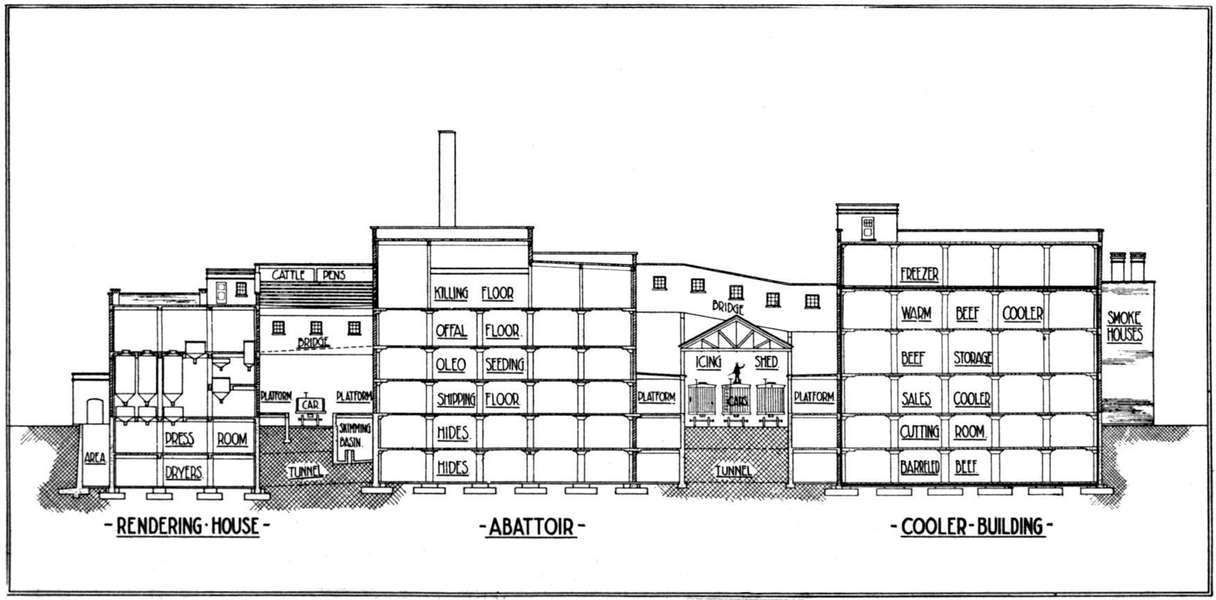
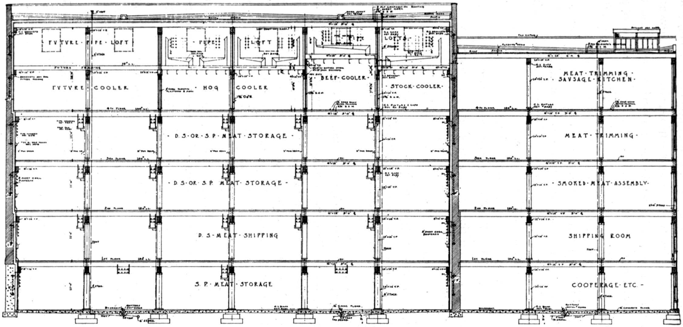
Plant No. 1.
—A moderate sized beef, mutton, and pork producing plant capable of slaughtering six hundred cattle, fifteen hundred sheep and fifteen hundred hogs daily, and taking care of the products of manufacture resulting therefrom. This design was developed upon the principle of gravity for movement of products with as little use of elevators as possible; the avoidance of excessive use of mechanical conveyors and contrivances; the grouping of buildings intended for hot or cold temperatures; economy of operation, and for minimum car movement.
LoadingFacilities.
The general arrangement provides for wagon and dray loading facilities fronting the main thoroughfare. The garage and office are at the left and right sides of the court. Three tracks are situated between the two groups of buildings to take care of the car loading. Usually the refrigerated products are loaded upon the east track, and non-refrigerated products, such as hides and bones, and the oleo department products, upon the west track. The intermediate track is used for the storing of cars. By use of the connecting platform at the south end either kind of cars can be
loaded on either track. A separate non-interfering railroad spur is provided for unloading coal, and cotton seed oil, and for loading tallow, while a distinct track is provided for loading cars of dry salt meats from the pork warehouse.
ProducingDepartment
—The abattoir is made the center of distribution, with the refrigerated buildings and departments directly communicative, situated nearby. The rendering and manufacturing departments—users of steam and power—are grouped near to the abattoir and to the power plant, while the buildings requiring refrigeration are grouped together and isolated from the manufacturing buildings. The stock pens connected with the plant
FIG. 5.—PLANT NO. 1, MODERATE SIZE PACKING HOUSE.
AbattoirBuilding
This building, six stories high, is given over to the following uses: Fourth floor, slaughtering; third floor, treatment, separation and cooking of by-products and manufacture of casings; second floor, oleo oil manufacturing; first floor, oleo oil storage, and shipping purposes; basement and sub-basement, storage of tallow and curing of hides.
RenderingBuilding are to the left of the manufacturing groups, but are not shown on the plan.
—Divided into two sections and separated by partitions, one side is used for the refining of cotton seed oil and the manufacture of edible tallows; the other side for cooking blood and rendering inedible tallows. The floors are used as follows: Second floor, level with viscera separating floor in abattoir, from whence raw stock is trucked to the filling floor without requiring use of elevators for filling of tanks; first floor, tank bodies and receptacles for collection of tallow. The skimming vats to which the tank residue, after drawing off the tallows, is passed, are level with this floor, enabling the separation and floating of the tallow and its collection; basement for press room, and sub-basement for drying tankage.
FIG. 6. EXTERIOR VIEW BEEF, SHEEP AND PORK PLANT.
The tank water to be evaporated is collected and passed to a separate building for treatment and evaporation.
LiveStock
The live stock pens are situated to the left of the rendering department extending north of the oil storage tanks from which position leads an incline, delivering the live stock into an elevated storage pen covering the area between the rendering house and the abattoir, and over the dressing room.
IcingDepartment
—Facilities for manufacturing ice for cooling cars are provided in the space directly north of the abattoir building. The three railroad tracks between the two groups of buildings are covered with a protecting shed, and from the bottom member of the trusses are suspended trolley rails for handling buckets of ice to be dumped into the tanks of the refrigerator cars.
CoolerBuilding
—The dressed beef, mutton and pork is transferred via bridge with chain conveyors, carrying the carcasses from the slaughtering house floor to the cooling rooms situated upon the third floor of the cooler building. From this floor the carcasses are conveyed for storage purposes to the second and first floor, and from there they are passed to the cutting room, city sales department, or cars. The basement and sub-basement are used for curing beef and pork joints. The fourth floor of this building is set aside for freezing products which, after being frozen, are shipped for storage to other premises owned by the same company.
FIG. 7. SECTIONAL VIEW INDICATING LEVELS AND COMPARATIVE LEVELS OF DEPARTMENT FLOORS.
The fourth floor of the pork house is utilized for chilling hogs; the third for cutting them, and all floors below for curing purposes. Note, the arrangement whereby the pork house and the cooler building are each connected with the team-loading platform and also closely arranged for car loading.
—A manufacturing building given over to the production of sausage, smoked meats, lard and the packing and shipping of same is immediately north of the cooler and pork buildings, and connected thereto at all floors where necessary. The city shipping department has its allotted space on the ground floor of the cooler building and the products finished in the manufacturing building move south toward the team loading platforms.
In this instance, but which rarely occurs, the city’s main sewer system is located at a deep level, which affords proper drainage and permitted the construction of two cellars. There are, therefore, two stories practically under ground. This is a decided advantage from the standpoint of radiation exposure, and it also affords an opportunity to provide salt storage and cooperage
stowing spaces on two levels adjacent to the railroad tracks. It further provides a means for securing a connecting tunnel below the track level, thus providing facilities for a perfect interchange from all cellar departments. Of equal consequence is the opportunity to pass all pipes for water, steam and refrigeration, power and lighting wires, as well as products, from one department to another. This makes for a low upkeep cost, little exposure, less radiation and greatly reduces the annual upkeep.
PowerDepartment
—The boilers were placed on a floor level with the basement. The coal pocket into which coal is dropped extends to the sub-basement level, providing a comparatively large coal storage. At the sub-basement level are the ash collecting bins. From this level are provided elevators of the continuous bucket type for raising the coal and ashes to tanks provided for storage, from which the coal and ashes gravitate to the furnaces and disposal cars respectively.
The engine foundations extend to the sub-basement level, with the main engine situated upon the basement level. The pumps are located in part on the lower level. All pipes and wires leading to the operating department are carried through the sub-basement, permitting the arrangement of all exhaust and steam piping beneath the engine room floor.
GravitySystem
—Attention is called to the fact that in the rendering department, for example, the products in their steps of manufacture are handled by gravity entirely until the finished dried fertilizer is produced, which has to be elevated to the ground level for car shipment, or for wagon delivery. The same features are true of the abattoir, hides and tallow in casks only, requiring the use of elevators for shipment.
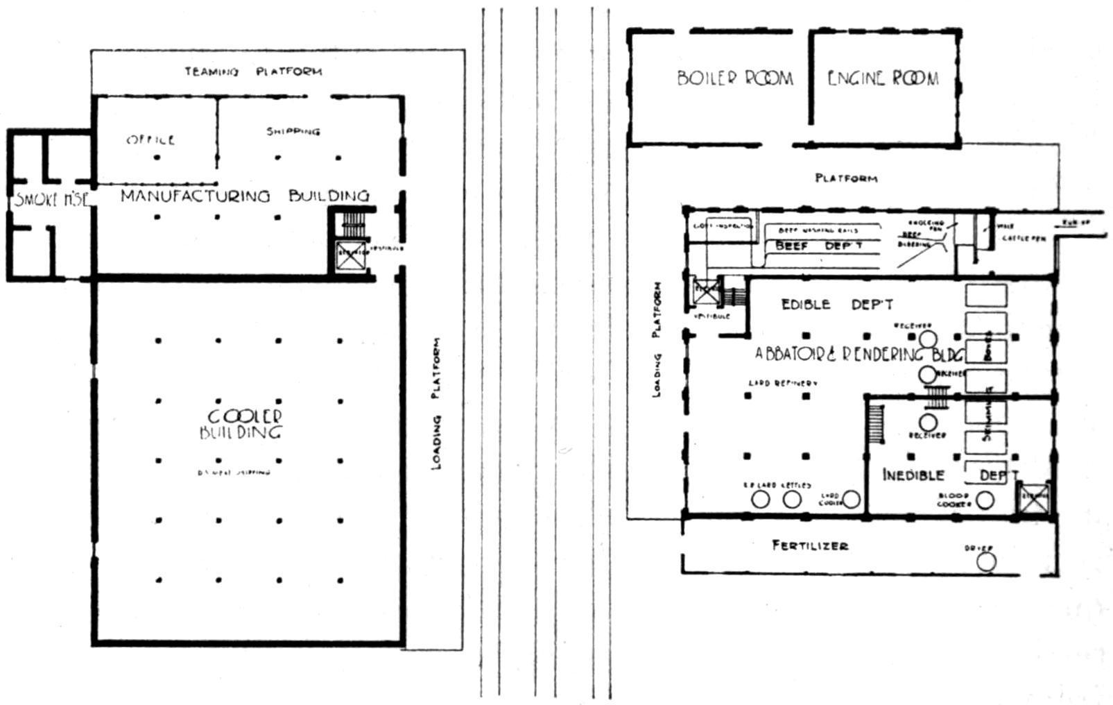
FIG. 8.—PLANT NO. 2, GROUND PLAN FOR COUNTRY PACKING HOUSE.
Plant No. 2.
—This plant was designed for a country point where the shipping by local freight cars or the city delivery was quite limited; where the major part of the product would be shipped by car, and where provision was made for quite an extensive growth. The capacity as designed being four hundred hogs and fifty cattle daily, with a complementary quantity of calves and sheep.
LoadingFacilities
—Again the three railways are provided for convenience in loading and for facilitating switching and icing.
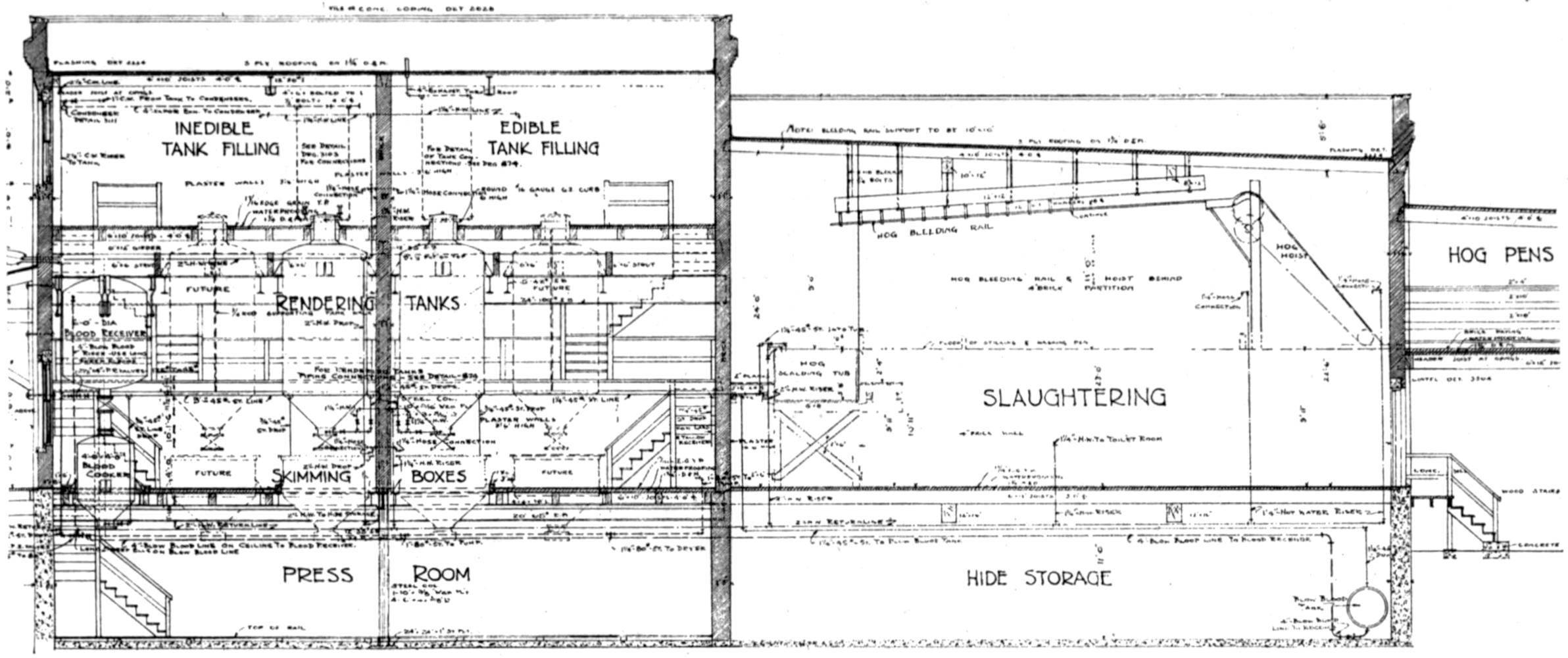
FIG. 9.—PLANT NO. 2, SECTION THROUGH SLAUGHTERING AND RENDERING BUILDING.
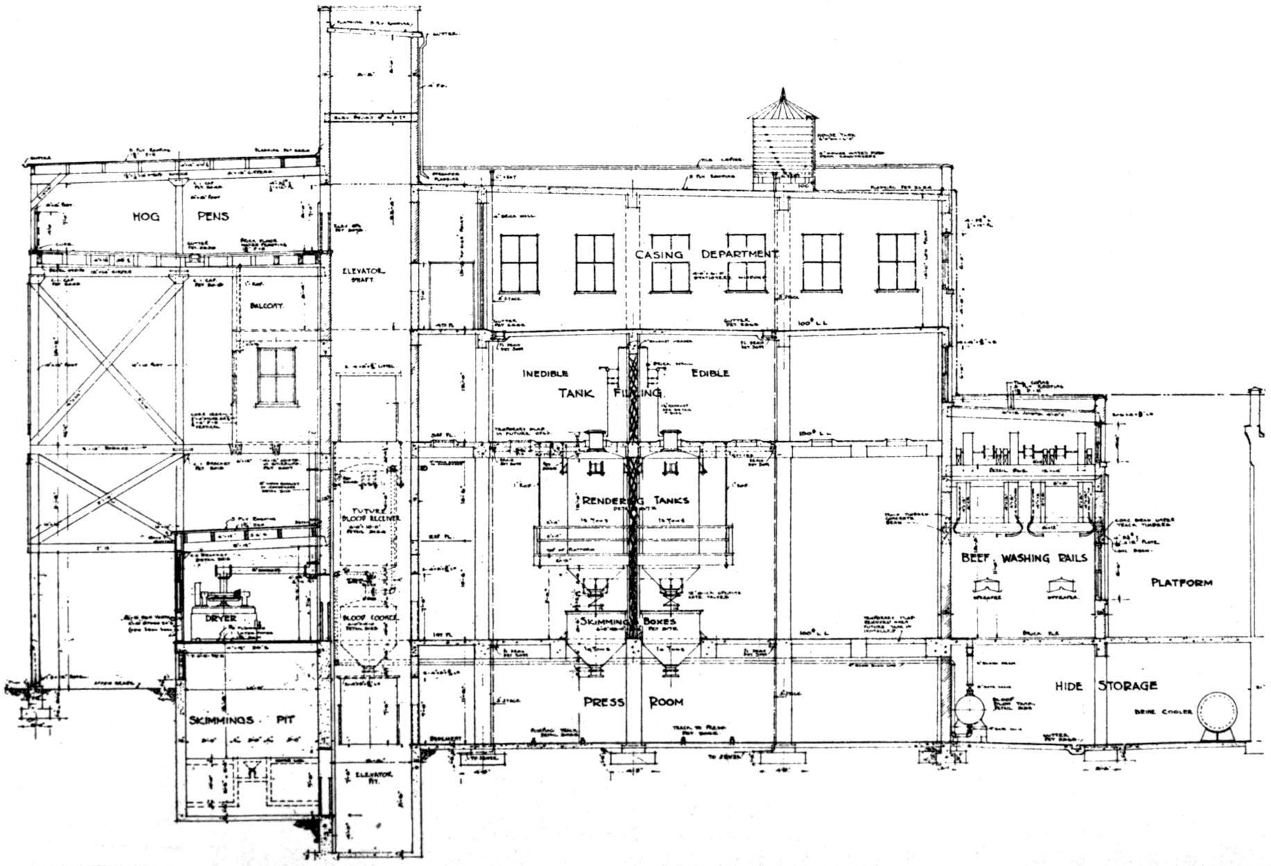
FIG. 10.—PLANT NO. 2, SECTION THROUGH MANUFACTURING BUILDING.
ProducingDepartment
In this plant the slaughter of hogs is the predominant business. The hog killing department was consequently designed amply large and for a growth to upwards of fifteen hundred hogs daily, while the rendering department provides for additional tanking facilities to be added as required. In this building, near to the source of production is placed a small air blast type of meat and leaf lard cooling space.
RenderingDepartment
—Owing to abattoir being isolated it was possible to set aside a portion of the building for the rendering department, and make the construction comply with the sanitary requirements as to light, air and ventilation. These features are illustrated by the sectional views.
LiveStock
The live stock receiving pens for cars and wagons are located on the ground as shown on plans, and a long ramp is arranged for the slow driving of hogs. Again, all products are passed downward in the process of manufacture.
IcingDepartment
FIG. 11. PLANT NO. 2, SECTION THROUGH COOLER BUILDING.
—Facilities are provided for harvesting ice from a stream situated north of the premises. The railroad tracks extend to the ice storage houses where facilities are provided for icing cars.
PorkBuilding
—Advantage was taken of the relative grouping and the space available to provide an open air hanging or drying room for hogs at a level of the killing floor and hog chill rooms. The hogs pass through this space on their way to the cooler. The pork building is arranged with chilling rooms on the upper floor and curing rooms beneath on all floors to and including the basement.
ManufacturingBuilding
Adjacent to the cooler building, space is provided for the making of sausage, cutting hogs, and trimming of sausage meat, processing of meats for smoking, packing and shipping.
PowerDepartment
—This is a minor matter since the electric current is purchased from a municipal lighting corporation, and the plant being in a cold climate, advantage is taken of these conditions. Note that in this plant every department except the killing department, which was made as large a unit as appeared to be necessary, may be extended without in any manner disturbing the relative situation of the departments. The uses of the several floors are shown in the sectional drawings.
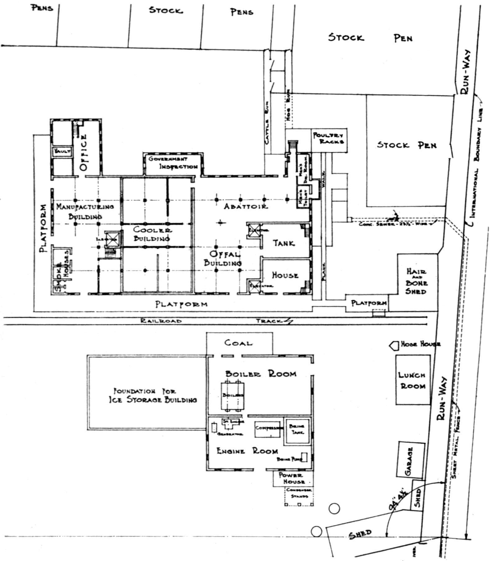
Plant No. 3.
Type of plant. The diagram (Fig. 12) is illustrative of a small local plant situated in a southwestern city, and built principally for a local mixed business. The plant will properly take care of one hundred hogs and fifty cattle daily, the necessary byproducts and the manufacturing departments, therefor. An ice business is operated in conjunction with this plant. The buildings are chiefly two stories in height. The plan and sectional drawings are sufficiently explicit to require no description.
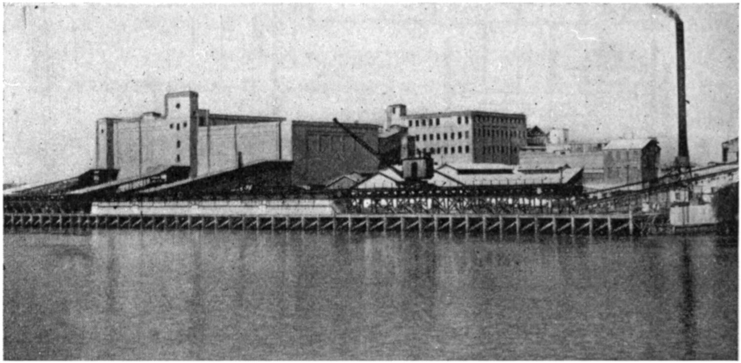
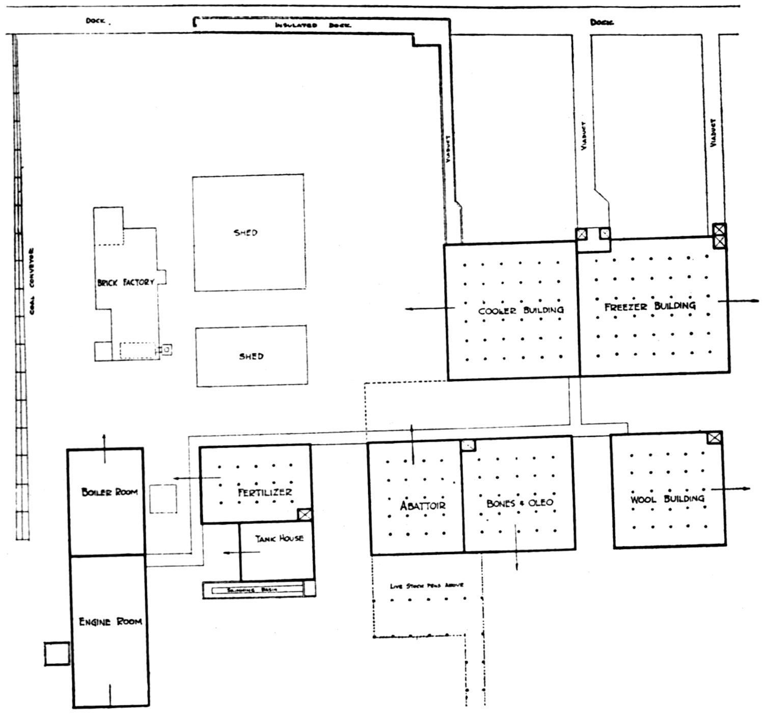
No. 4.
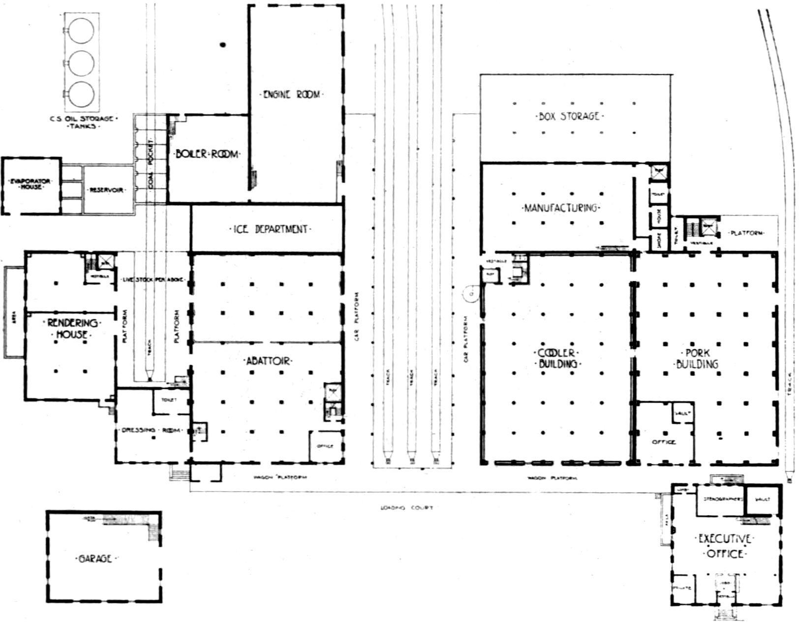
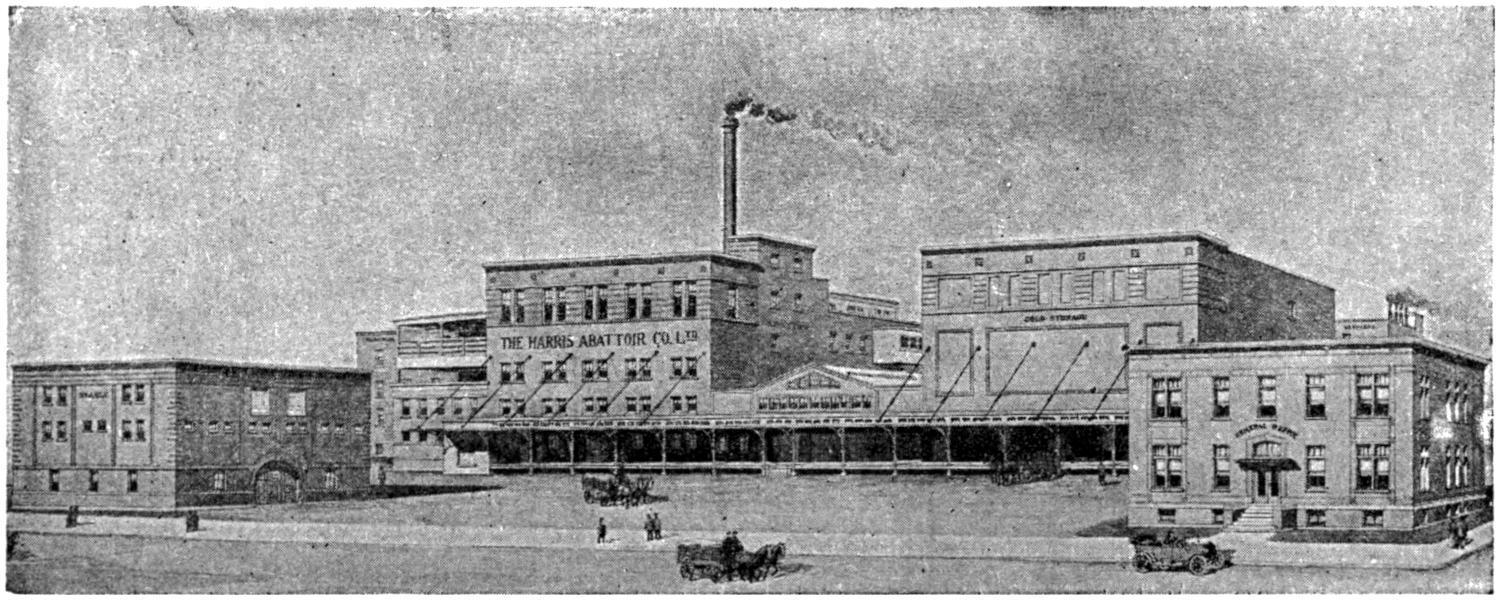
The accompanying vignette and ground plan are illustrative of an alongside deep water export plant. The photograph of front view illustrates the loading facilities which show ramps or
Plant
FIG. 12. PLANT NO. 3, GROUND PLAN OF SMALL LOCAL PACKING HOUSE.
inclines upon which conveyors are operated. These endless chains convey beef in quarter to the wharf at right angles thereto, where it is picked off the rail by ship’s tackle and lowered into the ship’s chambers.
Discussing the plant arrangement, note the position of the slaughter house with relation to the coolers and trace the movement of the products to the coolers, rendering, wool house. Also the further movement of the products to shipment. Particular attention is called to the arrows indicating the direction of growth of every department without disarranging the first intention as to movement, and minimizing the labor on the extended plant.
The steam producing department is in close proximity to the steam using buildings, viz: Power Department, Rendering House, Fertilizer and Slaughter House. Preference being given over electricity or refrigeration which can be transmitted longer distances at less loss.
How to Build.
—The question of design being settled the next matter of importance is the one involving the materials to be used in construction. That becomes a matter of investment and permanent
FIG. 13. PLANT NO. 4, SHOWING DEEP WATER EXPORT PLANT.
size or location of the buildings. Fireproof buildings are desirable on account of low cost of upkeep and a lower insurance rate. They are permanent in every way, but the difficult question is that of modifying, provided changes become necessary.
Fireproof Design.
—If decision is made for a fireproof building, re-inforced concrete is the first suggestion owing to its universal use as a building material, but there are several points to be given
FIG. 14.—PLANT NO. 4, GROUND PLAN FOR EXPORT PACKING HOUSE.
serious consideration before reaching a decision. One of these points being how to insulate so as to prevent losses. This matter will be taken up in a subsequent chapter describing a cold storage warehouse of eminent design. It is one of great importance.
Advantages of Fireproof Construction.
—The fireproof buildings have naturally a very great advantage in permanence from a standpoint of cost of upkeep and insurance charges, and from the greater loss of a cessation of business incident to destruction by fire. In most plants there are sufficient departments of such staple character so unlikely to be changed that it appears judicious to make them fireproof.
Slow Burning Construction.
—Many people are quite content with buildings of moderate height of slow burning construction; otherwise, a modified type of “mill construction” and with the use of sprinkler systems which minimize the insurance costs.
Approval of Plans.
There are many points in building construction to take care of in the matter of design, to meet the requirements of the insurance interests and local city building department regulations, which in the main coincide. Before entering into a contract to construct, it is well to have the drawings approved by the insurance boards and the city inspection bureau. It obviates expensive changes and additions. To build in such a manner as to bring the insurance rates to a minimum is certainly desirable. It is an advantage, too, to have the plant divided so that in case of fire the spread of the flames can be retarded and the fire confined to the building where it originated, or if some of the buildings are burned the balance can be saved. Fires invariably represent, to a well managed business, a far greater loss than is collectible on the insurance policies.
CHAPTER IV
REFRIGERATION EQUIPMENT
AMMONIA MACHINES AMMONIA COMPRESSOR CONDENSER RECEIVER COOLER
CONDENSING WATER UNIT BASIS COMPUTING FROM UNIT BASIS HOW RATED
FREEZER REQUIREMENTS FREEZERS IN SMALL PLANTS CYLINDER ARRANGEMENT WHY
BRINE CIRCULATION AIR CIRCULATING FORCE DRAFT COIL ROOM SYSTEMS BRINE
CHILLING BRINE METHODS TYPES OF BRINE COOLERS BALANCED BRINE SYSTEM
DIRECT EXPANSION TWO-STAGE COMPRESSORS.
Mechanical Refrigerating Equipment.
This agent is of great consequence in the operation of packing houses, and, therefore, it is deemed essential to explain the principles briefly; as well as to describe the uses.
Ammonia Machines.
—The use of ammonia refrigeration equipment either absorption or compression has so generally displaced all others for stationary or land use, and particularly in meat plants and cold storage houses, that for the present purpose it is unnecessary to go into a discussion of others. The compression system being so predominant in its use, a description of same is given.
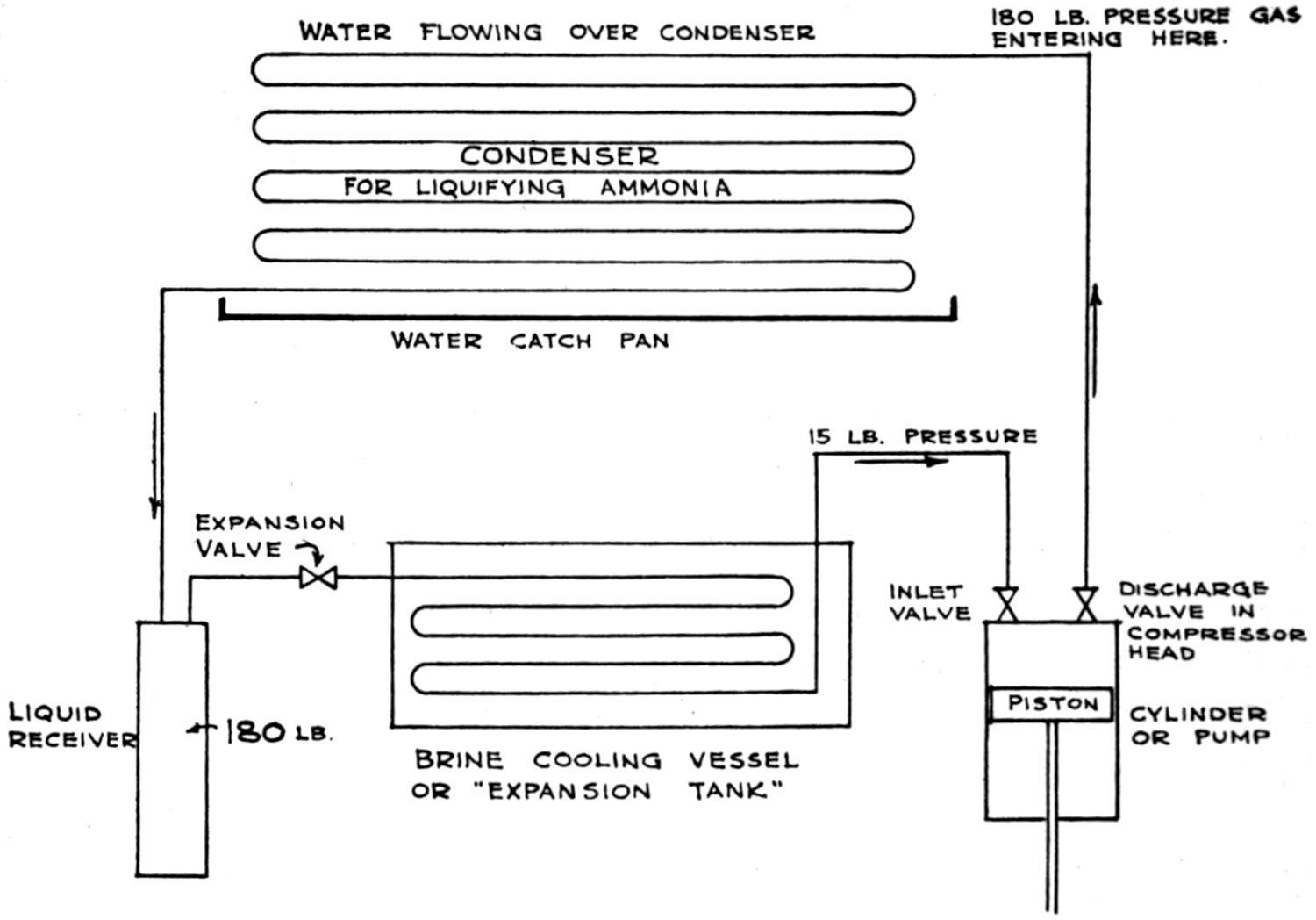
The diagram indicates a compression system in elementary form consisting of:
(1) A pump or compressor which withdraws the gas from the cooler or expansion tank, prepares and passes it to the condenser.
(2) The condenser or liquifier which gives to the water flowing over it the heat carried to it by the gas from the cooler.
(3) The cooler or expansion tank in which the heat extracted from the carcasses, the building walls or elsewhere, is passed to the ammonia gas for conveyance to the condenser.
—Leaving for a moment the description of the apparatus to acquaint the reader with ammonia: In the form used in a compression refrigerating machine, it bears the name “liquid anhydrous ammonia” meaning in a “dry liquid” form differentiating from the common household ammonia which is a water solution containing ammonia gas in variable quantity. The distinction between these two is that “anhydrous ammonia” will evaporate to naught; from household ammonia the gas will evaporate but the water will remain.
Ammonia is a chemical compound made up of one part nitrogen and three parts hydrogen and is expressed by the chemical symbol NH₃. It has some peculiar characteristics being analogous to water. It will assume a solid, liquid and gaseous form, at -115° F. and -28¹⁄₂° F. for solid and liquid respectively and will modify to a
FIG. 15. DIAGRAM SHOWING AMMONIA COMPRESSION SYSTEM.
gaseous form at any temperature above -28¹⁄₂° F. under “atmospheric” or conditions of no pressure.
Water, as is known, changes from a liquid to a solid at 32° F. and changes to a vaporous form at 212° F. but here the analogy ceases.
Ammonia has further peculiar advantages for use in refrigerating production that it becomes a liquid at variable pressures and temperatures; for example, when the temperature is reduced to 60° F. under a pressure of 92 pounds, when reduced to 80° under a pressure of 139 pounds and at 100°, under a pressure of 200 pounds; with variables above, between and below these conditions.
Ammonia, as will be seen, has variable forms and capacities under the conditions imposed upon it. Substances passing from a liquid to a gaseous form require heat to make this change and consequently absorb it; the complement to the giving up of heat when the process is reversed and the substance changed from a gaseous to a liquid form. The adoption or harnessing of these principles is the nucleus upon which mechanical refrigerating effect is built. A pound of water passing to steam will absorb about one thousand degrees of heat, ammonia has the same characteristic to a different degree. They both return the heat when the process is reversed.
Type of Machine Illustrated.
The diagram illustrates a single acting pump showing its piston, a liquifier or condenser where the ammonia is modified in form from a gas as received therein to a liquid; a receiver to which it flows and a cooler in which it is expanded and where the heat brought to it by the returning brine is picked up by the ammonia and carried to the condenser. The arrows indicate the direction of flow.
Compressor.
The “Compressor” is a pump, a cylinder fitted with a piston which withdraws the ammonia from the tank in which it is expanded. The piston is tightly fitted and when it travels in one direction, the gas flows in, filling the space, like any ordinary pump whether it be a water or gas pump. Upon the return stroke, the gas is compressed in the cylinder until the pressure in the piston is sufficient to equal or overcome that exerted against it accumulated in the condenser, when it is discharged thereto. There are spring
actuated valves interposed in the line of gas travel which close and retain in the condenser that gas which has been discharged, allowing the piston and compressor to repeat the just described performance many times per minute.
—The use of this element is to liquify the ammonia, really to extract the heat absorbed by the ammonia in the cooler and the heat generated in the compression. This condensing operation changes the form of the substance from gaseous to liquid. The most simple style of condenser is a series of pipes stacked together with ammonia on the inside of the several pipes, and water flowing over the outside. The gas on leaving the compressor is hot and at a high temperature, frequently as high as 250° F. or more, and the pressure from 140 to 220 lbs., depending upon the water supply, its temperature and quantity, and the area of the surface of the condenser.
The water flowing over the condenser absorbs the heat from within, the ammonia becoming cooled by contact with the comparatively cool walls of the pipe while flowing from one end to the other of the condensing coil, gradually changing from a gaseous to a liquid form.
—From the condenser the liquid ammonia is collected in the receiver so as to have a quantity stored for use and in reserve for the fluctuating requirements.
Condenser. Receiver. Expansion Valve.
—A small but important item in the system is the expansion valve which is a valve with a controllable opening and comparatively small. This is interposed in the line between the liquid receiver and the cooler or expansion tank.
Cooler or Expansion Tank.
—The next element is the cooler in whatever form it may exist, whether it be ammonia coils submerged in brine tank, shell and tube cooler built like a boiler in which the ammonia surrounds the tube through which the brine solution is pumped, or ammonia “direct” expansion coils in the air within a room, it matters not. At this point the heat given off by the substance to be cooled is absorbed by the ammonia and taken up for discharge to the water flowing over the condenser.
No substance will change from a liquid to a gaseous form unless heat be supplied to perform the work of making this change. At the outset it was stated ammonia will boil or evaporate at 28¹⁄₂° below zero Fahr. when under no pressure or in the open air. Further, if ammonia be contained in a vessel and the pressure be reduced below atmosphere, the boiling point is lowered still further. For example at 10.6 vacuum gauge pressure the boiling point will be 40° below zero.
Imagine a brine cooler such as a tank with coil submerged and surrounded by a brine solution: This brine is circulated through the building and by common knowledge we know it absorbs heat and is returned warmer than it was sent out. It is supplying the heat for boiling the ammonia gas.
Reverting to the expansion valves: Assume there is a pressure of 180 pounds in the condenser and a liquid temperature of perhaps 85 to 90 degrees; the same conditions existing in the receiver; also assume a pressure of 15 pounds on the ammonia coils which will produce a temperature condition of zero. In the diagram, the coil in the tank is attached to the expansion valve while on the other end of the coil is made the connection to the pump or compressor. This by its action is withdrawing the ammonia gas as rapidly as it is generated, due to the tightness of the piston, which if it is properly fitted will pump a vacuum upwards of 22 to 25 inches upon the system attached to it, unless gas be supplied to fill the space. In operation, the expansion valve is opened slightly, the liquid is freed into a space where the pressure is lowered, a condition created for expanding the ammonia to a gas and the heat contributed by the surrounding brine is absorbed by the ammonia changing from a liquid to a gaseous form.
The Cycle.
—The cycle, therefore, is a gas in the expansion tank at low pressure and temperature, admitted to the pump or compressor under this condition, compressed to a small volume and increased in pressure, discharged in this condition to the condenser where it becomes a liquid and in a condensed form at a lowered
temperature and ready to return to the expansion tank to be used over again.
Ammonia gas is the heat carrier. If it be used in packing house service, either it absorbs the heat directly from the rooms in which the animals are suspended or the brine in the tank is circulated through the rooms to absorb the heat and carry it back to the cooler or expansion tank.
Condensing Water.
—In Chapter II reference was made to the condensing water for refrigerating system. This is important because the lower its temperature, the less the pressure will be created which means the less the power must be exerted in the production of the mechanical refrigerating effect. The water flowing over the condenser carries the heat to the sewer. Thus the heat from the carcasses, the sun heat on the walls of the building, the actinic rays through the windows, the heat from the men employed within, that from the electric lights within, and that absorbed from the earth upon which the building stands must all be collected and eventually passed into the sewer.
Absorption Equipment.
—Absorption refrigeration equipment is used to some extent in packing house work, but its complexity makes unnecessary an attempt of its description in this work.
Unit Basis.
—The unit basis of refrigeration commonly used in expressing quantity is tons of refrigeration, meaning the tons of refrigerating duty that can be performed per day of twenty-four hours. The standard measurement per ton as adopted by the American Society of Refrigerating Engineers, is a cooling effect equal to 288,000 B.t.u., being equivalent to the extraction of this quantity of heat from any substance.
It has been established by the Bureau of Standards that in freezing one pound of water at 32° F., to ice at 32° F., 143.5 British thermal units of heat must be withdrawn from the water. For convenience in practice the fractional part is ignored, and 144 B.t.u. per pound of water is accepted as standard in calculations.
Computing From Unit Basis.
—If 144 B.t.u. are withdrawn from each pound of water at 32° F. to convert the water into ice at the
same temperature, the melting of the pound of ice at the same temperature must re-absorb an equal heat in the process of freezing, consequently the melting of one ton (2,000 pounds) of ice to water at the same temperature would absorb 2,000 × 144 B.t.u., or 288,000 B.t.u., the accepted standard for computing the heat absorbed in the performance of one ton of refrigeration duty. In ice melting this absorption of heat is latent, not sensible to the thermometer, as no change is apparent by thermometer test in the temperature of the ice and the water, nevertheless an appreciable cooling of surrounding is measurable by thermometer wherever ice melting takes place; for example, in an air-tight room, or in contact with solid substances, or with liquids, having a higher temperature than 32° F.
How Rated.
The rating of refrigerating compressors as usually stated by manufacturers is expressed in tons. This refers to the tons of duty that a machine will develop in a period of twenty-four hours continuous operation under assumed conditions of about fifteen pounds gauge, back or suction pressure, and 185 pounds head pressure. To perform this duty the compressor should be of sufficient size to displace or pump a volume of gas equal to 4¹⁄₄ cubic feet per minute. This rating of the machine is proper when you are producing temperatures of about 32° F. or over, and presupposes the plant to be properly balanced as to condensers, and to be properly provided with liquid receivers, oil extractors and other complementary equipment.
Freezer-Requirement.
—The growing demand for freezer space in and about packing houses, however, is so important that special means and methods must be provided to meet the conditions. It is impossible to produce freezer temperatures and conditions under the same back pressure as described above; the back pressures must be lowered and in doing so the capacity of the compressor is reduced very rapidly. The same compressor producing one hundred tons refrigeration duty at fifteen pounds back pressure and 185 pounds head pressure will only perform half the work when operating under
a back pressure of five pounds, the head pressure remaining the same.
The purchaser must never lose sight of the fact that in cooling freezer spaces the compressor capacity is reduced practically by half and that this is applicable to all portions of the system working under these conditions.
System to Adopt.
—No hard and fast rule can be adopted regarding the system of refrigeration to be adopted, whether by use of brine circulation or direct expansion. The case in hand and the nature of the business to be done seems to govern. For example, if the plant in which the business is mixed, wherein hogs, cattle and sheep are killed, curing performed, and lard made, with a limited amount of freezing, brine circulation for general use would seem the better. The excellent results obtained by the use of spray coolers, later described, seem to point to its use in chilling coolers, with brine circulated through ceiling or wall coils for cooling storage rooms.
Freezers in Small Plants.
If the plant be quite moderate in size and only sufficient to justify the installation of one compressor the amount of space required for freezing purposes is thus limited, and if commercial freezer space is available it is a question as to whether the operator can afford to deplete his small equipment capacity by installing freezers.
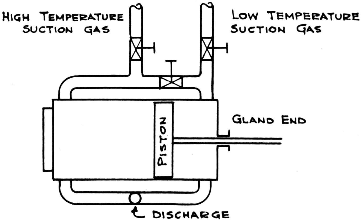
FIG. 16. SUCTION CONNECTION FOR DUO-PURPOSE COMPRESSOR.
Cylinder Arrangements.
If the plant be sufficiently large so that the machine equipment can be afforded in two units then it would be proper to install freezers. Supposing then that the plant justifies this arrangement the compressors would be connected to the brine tank for chilling purposes, and to the closed cooler for circulating purposes. The gland end of the compressors would be arranged so that they could be operated independently upon the freezer space at will.
Why Brine Circulation.
—The chief reason for using brine in the moderate sized plant is that with a reasonably large brine capacity there is a reserve cold (so to speak) stored in the brine which will permit of stopping the compressor, the brine continuing in circulation by pumping, and there is less likelihood of changes in temperature. Direct expansion chilling requires an almost constant machine operation.
Air Circulating.
—The chilling of packing houses and methods involved are various, each with its advocates. In Europe and where English methods are followed the system is chiefly forced draft. This system has been used to some extent in the United States, but the majority of the coolers are handled with lofts, and circulation therefrom is of natural sequence. The cellars and freezers are handled by pipes hung in the rooms.
Force Draft.
—The force draft or indirect cooling system consists of forcing chilled air, cooled by passing through batteries of expansion coils operated dry, or over which brine is passed, through a series of ducts, and withdrawing it; thence passing it through the coils and repeating. It is not favored among American packers owing to a belief that it increases shrinkage, and tends to darken beef; that large quantities of cold air are lost through open doors; because of the expense of operating fans, as well as the room taken up by ducts and the interference occasioned with meat rails.
Coil Room Systems.
The overhead bunker system as described under “Construction” in this work details the application of the United States practice.
Accepting the use of the coil room system and of still storage the question arises as to the application. A visit of inspection to the various packing plants throughout America will impress one with the fact of the existence of a wide variation of opinion and practice with regard to the methods of applying refrigeration for packing house purposes. There are two principal applications—direct expansion, wherein the ammonia gas is circulated through the coils throughout the premises, and brine circulation, open or closed, where chilled brine is circulated throughout the works.
Brine Chilling.
—The two types of brine chilling, open and closed, produce the same result, except as to the actual brine cooler, of which there are several, namely:
(1) Brine tank in which are submerged ammonia expansion coils.
(2) Double or triple pipe coolers in which brine and ammonia are circulated in annular spaces between pipes.
(3) Shell type coolers in which the brine is passed through tubes within a shell similar to an ordinary flue boiler.
For a close brine system, which is the term applied to a system where brine is circulated through pipes and not exposed to the atmosphere so as to absorb moisture, the shell type cooler is a convenient and economical means of chilling brine. It is so readily applicable to the use of a balanced system, thereby lessening the power requirement for pumping.
Double pipe coolers can be used in the same method, but are not quite so favorably considered owing to the aggregate quantity of joints.
Either the shell type cooler or the double pipe cooler can be safely used with an open system. The open type brine system is any system used wherein the cooling effect is produced by bringing the cold brine in direct contact with the air to be chilled, as in the spray system, the “Gardner” sheet system, or an open pan system.
Brine Methods—Recommendation.
Where it would seem best for other reasons to use a brine system, and the plant would justify the expenditure, it would appear well to use a double brine system—open brine in the hog chill rooms, and a closed system on the freezers, beef chill rooms, storage rooms.
Types of Brine Coolers.
—Open tanks with submerged coils are used on some plants. The investment is greater, but the risk is slightly less than in the use of closed type brine coolers, commonly called shell and tube type. Unless the engineering force of the plant is fully qualified and alert, there is danger of diluted brine and freezing the solution in shell type coolers, which is likely to split the tubes, causing leaks and the possibility of brine finding its way to the ammonia compressors, rendering them liable to damage of a serious nature. Whereas, with the open type tank and submerged coils, weakened brine might cause ice to form on the expansion pipes and render them inert, but no comparable damage could arise. However, we advocate an alert engineering force and the closed system.