The Research Handbooks in Money and Finance series presents a thorough analysis of recent scholarly developments in monetary and financial economics, forming an essential, authoritative and comprehensive reference guide to the field. Edited by esteemed international scholars, these Handbooks contain a wide range of specially-commissioned chapters covering the latest advances and research, and aim to be prestigious, high-quality works of lasting significance. Each Handbook consists of original contributions by an international team of scholars, and contributes to both the expansion of current debates and the development of future research.
For a full list of Edward Elgar published titles, including the titles in this series, visit our website at www.e-elgar.com.
Handbook of Corporate Finance
Edited by David J. Denis
Roger Ahlbrandt Sr. Chair in Finance, University of Pittsburgh, USA
All rights reserved. No part of this publication may be reproduced, stored in a retrieval system or transmitted in any form or by any means, electronic, mechanical or photocopying, recording, or otherwise without the prior permission of the publisher.
Published by
Edward Elgar Publishing Limited
The Lypiatts 15 Lansdown Road Cheltenham Glos GL50 2JA UK
Edward Elgar Publishing, Inc.
William Pratt House 9 Dewey Court Northampton Massachusetts 01060 USA
A catalogue record for this book is available from the British Library
Library of Congress Control Number: 2023951004
This book is available electronically in the Economics subject collection http://dx.doi.org/10.4337/9781800373891
ISBN 978 1 80037 388 4 (cased)
ISBN 978 1 80037 389 1 (eBook)
Typeset by Cheshire Typesetting Ltd, Cuddington, Cheshire
Contributors
Nihat Aktas, WHU – Otto Beisheim School of Management, Germany
Alice Bonaimé, University of Arizona, USA
Audra Boone, Texas Christian University, USA
Murillo Campello, Cornell University, USA
Jeffrey L. Coles, University of Utah, USA
Naveen D. Daniel, Drexel University, USA
David J. Denis, University of Pittsburgh, USA
Diane Denis, University of Pittsburgh, USA
Isil Erel, Ohio State University, USA
Murray Z. Frank, University of Minnesota, USA
Laurent Frésard, Università della Svizerra italiana, Switzerland
Vidhan K. Goyal, Hong Kong University of Science and Technology, Hong Kong
Kristine W. Hankins, University of Kentucky, USA
Jarrad Harford, University of Washington, USA
Gerard Hoberg, University of Southern California, USA
Yeejin Jang, University of New South Wales, Australia
Kathleen Kahle, University of Arizona, USA
Gaurav Kankanhalli, University of Pittsburgh, USA
Jonathan M. Karpoff, University of Washington, USA
Mark Leary, Washington University, St. Louis, USA
Michelle Lowry, Drexel University, USA
viii Handbook of corporate finance
Nadya Malenko, Boston College, USA
Lalitha Naveen, Temple University, USA
Greg Nini, Drexel University, USA
Naman Nishesh, University of North Carolina, USA
Vasudha Nukala, Washington University, St. Louis, USA
Paige Ouimet, University of North Carolina, USA
Gordon M. Phillips, Dartmouth University, USA
Elena Simintzi, University of North Carolina, USA
David C. Smith, University of Virginia, USA
Luxi Wang, University of Pittsburgh, USA
Michael S. Weisbach, Ohio State University, USA
Michael D. Wittry, Ohio State University, USA
Introduction to the Handbook of Corporate Finance
David J. Denis
This volume provides a collection of chapters summarizing scholarly research in the field of corporate finance. The field studies how companies acquire and allocate scarce capital. Accordingly, corporate finance research encompasses topic areas such as corporate financing and payout policies, investment decisions, and governance arrangements that protect the interests of capital providers. The chapters in this volume provide readers with a snapshot of the ‘state-of-the art’ critical thinking and evidence on a variety of issues within these general topic areas. Though the topics covered are arguably among the most important in corporate finance, they are not meant to be an exhaustive set under the corporate finance umbrella. Nonetheless, the volume should serve as a comprehensive resource for doctoral students, faculty, and practitioners interested in corporate finance.
In this introduction, I provide a brief overview of the chapters that make up the book. My purpose in doing so is to provide readers with a roadmap of the topics covered and how the various chapters fit together. It is not meant to be a substitute for reading the chapters themselves.
The book begins with Chapter 1 by Diane Denis on the corporate objective function. Although there is a long history within finance of relying on shareholder wealth maximization as the appropriate criterion for evaluating corporate finance decisions, increased political and societal demands for corporate social responsibility (CSR) have led some to argue that the corporate objective function should be re-evaluated. Denis details the economic underpinnings of the shareholder wealth maximization objective and critically evaluates alternative approaches, such as stakeholder welfare maximization. Her analysis reveals significant problems with these alternative approaches, and reaffirms shareholder wealth maximization as the most appropriate criterion for evaluating corporate decisions.
Part II of the book summarizes research in the classic corporate finance questions of Corporate Financing and Payout Policies. In Chapter 2, Murray Frank and Vidhan Goyal note that, after more than 50 years of research, corporate capital structure decisions remain a challenging puzzle to understand. Over this time, finance scholars have uncovered a number of useful empirical facts that establish important roles for taxes, funding needs, and informational imperfections in explaining observed capital structure decisions. Yet, after summarizing the available empirical evidence, Frank and Goyal conclude that there is still no generally accepted unified theory that can account for all of the stylized facts. Their survey thus points to the need for continued research in this area.
Chapters 3 and 4 survey the literature on corporate payout policy. In Chapter 3, Mark Leary and Vasudha Nukala survey studies that empirically analyze dividend policy. As their survey indicates, this literature has uncovered a large set of stylized facts about the nature of (and trends in) dividend policies that are not in dispute. At the same time, however, there remains considerable disagreement on whether and why dividends matter. For example, do dividends directly impact firm value or are they simply signaling
value-relevant information to investors? In summarizing the evidence on the various possibilities, Leary and Nukala highlight the most productive areas for future research.
In Chapter 4, Alice Bonaimé and Kathleen Kahle document that share repurchases have become an increasingly common form of corporate payout, totaling nearly $1 trillion in 2018, an amount that exceeded total dividends paid in that year by U.S. companies. Bonaimé and Kahle survey the recent literature that seeks to understand: why companies increasingly prefer share repurchases to dividends; whether these motives lead to decisions that are value-increasing for shareholders; and how repurchases interact with other corporate finance policies such as liquidity management, investment decisions, and hedging policy, as well as other important considerations such as product market competition and labor contracts.
In Chapter 5, David Denis and Luxi Wang explore the causes and consequences of corporate cash holdings. As their survey indicates, cash has become an increasingly large component of corporate balance sheets over the past 50 years. Their survey assesses: (i) cross-sectional and time-series patterns in cash holdings; (ii) theoretical explanations for these patterns; and (iii) recent empirical evidence that sheds light on the primary causes and consequences of such holdings.
In Chapter 6, Greg Nini and David Smith document an important innovation in the corporate financing market – the use of leveraged loans. Their analysis reveals that this market has grown to a size comparable to that of high-yield corporate bonds, thereby providing risky issuers important access to debt capital. Because these issuers have sharply different risk profiles from those of investment-grade bond issuers and bank borrowers, Nini and Smith focus much of their survey on the distinct features of primary markets, secondary markets, and contracting structures within the leveraged loan market.
Part II concludes with Chapter 7, by Kristine Hankins and Gerard Hoberg, on corporate risk management policies. If access to capital is important to firms, the ability to manage the uncertainty of cash flows should be valuable to shareholders. At the same time, risk management can be a vehicle for tailoring the company’s risk profile to managerial preferences rather than shareholder preferences. Hankins and Hoberg provide a broad taxonomy for categorizing corporate risks, and analyze how managing risk can be valuable for various corporate stakeholders. With this taxonomy in mind, their chapter also surveys the broad array of financial and operational hedging tools studied in the literature.
Part III of the book explores research in the areas of Mergers, Acquisitions, and Takeover Defenses. M&A transactions represent some of the largest discrete investment decisions that companies make, and result in a substantial restructuring of the ownership and control of corporate assets. An enormous body of scholarship has documented (among other things) the motives for these transactions, their wealth consequences for various stakeholders and parties to the deals, the sources of these wealth consequences, and the various forms that the transactions can take. Part III focuses on more recent research that extends this prior literature in several directions, including: the intricacies of the deal process; the proliferation of cross-border merger activity; the existence of merger waves; and the various defensive tactics employed by firms in the face of unwanted takeover advances.
In Chapter 8, Nihat Aktas and Audra Boone survey the nascent literature on the private component of the takeover process. Historically, merger negotiations have been secretive
and their details beyond the reach of finance scholars. However, access to mandated merger-related regulatory filings and surveys of practitioners has opened the ‘black box’ of the negotiations process to empirical analysis. Aktas and Boone summarize novel evidence in three areas: (i) the primary drivers of deal initiation and target-acquirer matching; (ii) the role played by internal M&A teams and external advisors; and (iii) the determinants of the method of sale.
In Chapter 9, Isil Erel, Yeejin Jang, and Michael Weisbach explore the causes and consequences of cross-border mergers and acquisitions. Although most prior research has focused on domestic deals, Erel et al. note that roughly one-third of merger activity around the world since 1990 has involved cross-border deals. Their survey highlights research on the factors leading firms to acquire a firm in another country. These factors include differences in economic development, laws, institutions, culture, labor rights, protection of intellectual property, taxes, and corporate governance.
In Chapter 10, Jarrad Harford surveys the literature on the underlying drivers of merger waves. This literature encompasses aggregate merger waves, industry-specific waves, and waves of cross-border transactions. Although no single explanation for waves seems to dominate, the bulk of the evidence supports the conclusion that merger waves are a response to shocks to operating environments that facilitate the efficient reallocation of corporate assets. The clustering of transactions is often driven by financing conditions that are conducive for completing the deals. In addition, there is some evidence that market misvaluation potentially plays a role as well.
Part III closes with Chapter 11, by Jonathan Karpoff and Michael Wittry, which traces the evolution of takeover defenses over several decades. Their survey summarizes how firms use takeover defenses, the extent to which they forestall takeovers, the costs and benefits of adding/removing defenses, and the net effect of such defenses on firm value and operations. This literature shows that the costs and benefits of defenses vary across firms and over an individual firm’s life cycle.
Part IV summarizes recent work in the important areas of Corporate Ownership and Governance Structures. In Chapter 12, Jeffrey Coles, Naveen Daniel, and Lalitha Naveen review the large literature that analyzes how corporate boards perform their two primary functions: monitoring executive performance and advising the top executive, with a particular focus on studies that have emerged over the past 15 years. These studies analyze how factors such as director characteristics, skill sets, personal connections, busyness, and incentives affect the ability and willingness of the board to perform their duties as monitors and advisors. Moreover, because the assignment of directors to firms is not random, a large part of this literature must address the endogeneity between board structure and firm outcomes. Coles, Daniel and Naveen also review the various ways in which this issue has been addressed in the recent literature.
Much of the research in corporate finance over the years has focused on public companies because: (i) these companies have traditionally been economically more important; and (ii) data has been more readily available for public than for private companies. As data constraints have been reduced, an increasing amount of research has incorporated findings from private firms. In Chapter 13, Michelle Lowry reviews research that documents how private companies have chosen to remain private longer in recent years, and that they increasingly resemble public companies. First, there is growing overlap in the sources of capital for public and private firms. Second, governance structures of private firms have
evolved to meet the demands that are more often associated with public firms. Third, although a frequently stated motivation for going public has traditionally been the desire to obtain liquid shares to be used as acquisition currency, firms are increasingly growing via acquisitions even prior to going public. The bottom line is that markets have evolved such that there is now considerably less distinction between public and private ownership of firms.
In Chapter 14, Nadya Malenko combines aspects of ownership structure and governance in providing an overview of research on information flows within corporations. Because effective decision-making requires information, but such information is dispersed among multiple agents within a firm, both the firm’s organizational structure and its governance arrangements can affect how information is produced and ultimately used. In surveying the theoretical and empirical studies on this topic, Malenko focuses on three key areas: (i) the choice between centralized and decentralized decision-making; (ii) the composition and decision-making of the board of directors; and (iii) the role of shareholder activism in affecting communication among shareholders and between shareholders and management.
Much of the research in corporate finance explores the impact of market frictions on corporate finance decisions. Traditionally, this research has focused on frictions related to asymmetric information and agency problems. This focus has considerably deepened our understanding of how decisions are made and their impact on stakeholders. In recent years, however, scholars have identified several other important influences on corporate decisions. Part V of the book – Other Important Influences on Corporate Finance Decisions – highlights research on three of these influences: uncertainty, product market competition, and considerations related to labor.
In Chapter 15, Murillo Campello and Gaurav Kankanhalli note that uncertainty over future business conditions is a ubiquitous feature of corporate decision-making. However, this uncertainty can arise from many different sources and can be difficult to measure. After providing a simple conceptual framework for understanding how several corporate decisions are affected by uncertainty, Campello and Kankanhalli review recent advances in the measurement of uncertainty, distinguishing between aggregate uncertainty and firm-specific uncertainty. They then survey the evidence on how uncertainty shapes important corporate financial decisions, such as corporate investment, the composition of firm assets, innovation, liquidity management, corporate payouts, and mergers.
In Chapter 16, Laurent Frésard and Gordon Phillips review the literature that studies how product markets and competition interact with corporate financial decisions. This work shows that not only are firm decisions influenced by the product market(s) in which they operate, but that these decisions also directly shape those markets and the resulting competition. Specifically: the nature and intensity of interactions in the product market appears to influence the ability of firms to obtain financing (and on what terms); it impacts their investment, acquisition, and innovation decisions; and it helps shape their organizational and governance structures. Frésard and Phillips conclude that product market considerations have first-order effects on firm decisions.
In Chapter 17, Naman Nishesh, Paige Ouimet, and Elena Simintzi survey the relatively nascent literature that lies at the intersection of labor economics and corporate finance. As is true in the literature on product markets and corporate finance, a common theme that runs through the labor/finance literature is that decisions made by firms have an
impact on labor, while labor market considerations affect firm decisions. The authors review evidence in three primary areas: (i) the relationship between ownership and labor market outcomes; (ii) the relationship between capital structure decisions and labor markets; and (iii) the connection between labor and inequality within firms and investments in technology adoption.
These chapters provide a thorough survey of the important work that has been done on some of the most critical decisions corporate financial managers make. Of equal importance, however, is that each set of authors outline a number of unresolved issues that should be addressed in future research. As noted at the outset, this introduction is meant to give readers an overview of how the book is organized and how the chapters fit with one another. I hope that it has provided readers with the motivation to dig deeper into a careful reading of these excellent contributions.
PART I
CORPORATE OBJECTIVES
Another random document with no related content on Scribd:
forming the angles of a square. The cables are separately clamped, the top plate overlapping the clamp straps. The multiple cable enters on one side; three singleconductor cables enter on the opposite side, and two on each of the intermediate sides. The top plate is provided with a lowering ring.
The junction boxes. These boxes, in different sizes, are used in splicing multiple and single-conductor cables; they consist of two rectangular plates of iron or steel united by four ½-inch bolts at the corners. The plates are hollowed in the middle to form a chamber to receive the Turk’s-heads and the joints connecting the conductors. The ends of the plates are curved to admit the cable ends. The Turk’s-heads are clamped to the lower plate by straps and screw bolts, the cavity of the upper plate covering them when bolted in position. Each cable end is thus made fast before the box is closed.
The distribution box buoy. This buoy is used to mark the position of the distribution box during the planting of mines and subsequently, in practice and in service, until such time as the mine commander desires to remove it. It may be either a can or a keg buoy—a beer keg of one-half barrel capacity is well suited for this purpose.
The mine buoy. This buoy is used to mark the position of the mine when planted. It may be a small can buoy, preferably cork filled, or a piece of wood with a hole bored through it. The size of the buoy is determined by the swiftness of the current. It is attached to the maneuvering ring of the buoyant mine by 60 feet of ½-inch rope.
The measuring reel and frame. The frame consists of two longitudinal pieces, 3 by 4 by 66 inches, placed 17 inches apart, center to center. At 11½ inches from each end two cross pieces, 3 by 4 by 20 inches in length, are fastened to the longitudinal pieces with through bolts. At the center point of these cross pieces are placed standards, 3 by 4 by 16¾ inches, which have journals for the axle of the reel, counter-sunk in their upper ends. Two iron braces, one on each side, hold each standard firmly in a vertical position. An iron clamp is also attached to the upper ends of the standards, by means of which the axle is prevented from jumping out of the journals. Distance from center to center of standards is 43 inches.
The iron axle of the reel is 1½-inch round iron, 54 inches in length. At each end of the axle a screw thread is cut for the nut which holds the crank in place. Inside the screw thread the axle is squared to receive the socket of the crank. Two collars prevent the wooden reel from binding on either standard. The cranks are of the usual design. The drum of the reel is 8½ inches in diameter; heads are 2½ inches thick, made in two layers, cross-grained, and are 24 inches in diameter; length of drum over all is 36 inches. Iron plates are fastened in the center of each head, through which the axle passes. The reel is prevented from turning on the axle by keys.
Three ¾-inch rods pass through the iron plates and drum and bind these parts firmly together.
At 6 inches from the ends of the longitudinal pieces a hole is bored to receive a lag screw, ½ inch by 6 inches, by means of which the whole apparatus can be firmly fastened to the deck.
The brake is a piece of 3 by 3 by 36 inch hardwood, used as a lever to bring pressure on the drumhead. There is one for each side, and, when not in use, each rests on one of
the longitudinals, being held in place at one end by two staples and at the other end by a bolt and pin.
Near the drum on one head is a hole through which the inner end of the measuring line can be passed and stapled to the outside of the head.
The cable-reel frame. The frame is made in two parts which, when in use, are held in proper relative positions by means of two iron ties provided with turnbuckles at their centers. The ends of these ties are bent over at right angles and fit in sockets in the two end parts.
Each end part consists of a standard having an iron head through which works a screw turned by a small lever, the upper end carrying a journal in which the end of the reel axle rests. The lower end of the standard rests on a horizontal piece and has a diagonal brace on each side, the outer ends of these braces being dovetailed into the longitudinal piece and the inner ends into the standard near the top. Dovetailed into the longitudinal piece at its middle point is a piece extending out at right angles, bottom flush with bottom of the longitudinal. A diagonal brace similarly fastened prevents any outward movement of the standard. The whole is held firmly together by bolts and lag screws.
Lag screws are also provided, by means of which the ends of the frames can be fastened to the deck of the vessel if desired.
The reel axle is 2½ by 2½ inch squared iron, rounded at the ends for 6 inches to fit the journals of the frame. A disk secured by a set-screw at one end of the axle and the friction brake wheel at the other end hold the axle in position with respect to the reel.
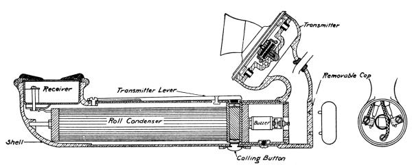
FIG. 11.—BOAT TELEPHONE, MODEL 1906.
The brake wheel is 18 inches in diameter. The friction band is 1½ inches by ⅛ inch, and is fastened at one end to one of the standards of the frame. The other end is attached to a lever whose fulcrum is also attached to the same standard.
Boat telephones. The different models in use are as follows:
(a) Model 1904. The system consists of two telephone hand sets, a buzzer, and a battery of dry cells of about 8 volts, all connected in series by means of cable and earth connections.
In operating the telephones a call is made by pressing the button, and when talking the lever is held down.
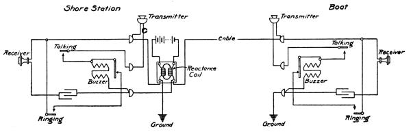
(b) Model1906.—The system consists of two telephone hand sets, a reactance coil, and a source of energy that will furnish about 15 volts, dry cells preferred, connected as shown in figure 11. The terminals do not have to be poled, as the receiver is not in the primary circuit and can not be demagnetized.
To regulate the buzzer, remove the cap in the base and with a small screw driver loosen the lock nut on the center screw (a small portion of a turn is all that is necessary). With a smaller screw driver the screw may be adjusted to increase or decrease the rate of vibration, increasing or decreasing the sound. Then tighten the lock nut. In case the contact is dirty the entire buzzer and condenser may be removed by disconnecting the cord and removing the screw on the back of the telephone just below the call button. As the contacts are aluminum, this will seldom have to be done.
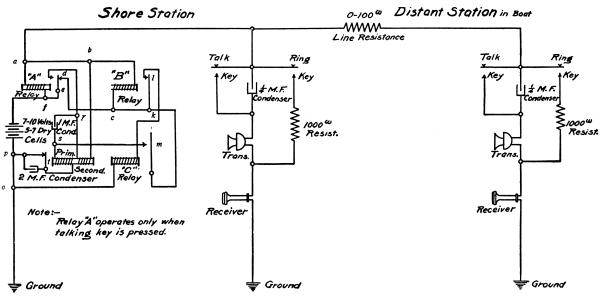
(c) Model1909.—The system consists of two telephone hand sets, an apparatus box, and a battery of from 7 to 10 volts, all connected as shown in figure 12. The talking and ringing circuits are normally open at the talking and ringing buttons, respectively.
Apparatus box.—Seven dry cells in series should be connected to the posts of the apparatus box marked “+” and “-,” and the post marked “G” connected to a ground plate.
Shore hand set. The blue cord of the shore hand set should be connected to the ground plate. Either of the red cords of the shore hand set should be connected to the post in the apparatus box marked “L” and the other to the conductor in the cable that is to be used for telephoning purposes.
Boathandset. The blue cord of the boat hand set should be connected to the ground plate and one of the red cords to the conductor in the cable to which the hand set on the shore is connected. The other red cord is free.
Signaling.—From figure 12 it will be seen that in either hand set, when neither the ringing nor the talking switch is closed, a condenser within the hand set is in series with the transmitter and the receiver, so that the practical effect is to permit an alternating or variable current to pass through the transmitter and the receiver, but to prevent a direct or continuous current from so doing.
By pressing the ringing key of either hand set the circuit in that hand set is closed through the 1,000 ohms resistance and the receiver to ground. Thus, when the ringing key of the boat hand set is pressed, this allows the direct current from the battery to pass (see fig. 12) through f, e, d, c, “B,” b, a, line, the ringing key, 1,000-ohm resistance, and receiver of the boat hand set, to ground, and back through o and p to battery. Similarly, a
circuit through the battery, f, “A,” and a, is made, thus placing relays “A” and “B” in parallel. The relay “B” operates, but relay “A,” being less sensitive than “B,” does not operate. Relay “B” closes the circuit at l, and thus completes the circuit from battery through f, e, d, c, k, l, “C,” o, p, back to battery. This causes relay “C” to operate and to complete a local circuit from battery through f, e, d, k, m, s, primary, t, vibrator, p, back to battery, causing the vibrator to vibrate and inducing in the secondary winding of the induction coil an alternating current, which passes through the 1 M. F. and 2 M. F. condensers, through the hand sets in parallel, and by alternately increasing and decreasing the attraction of the receiver magnets for their diaphragms produces a loud humming sound in each receiver.
Similarly the shore station may call the boat station.
Talking. When the ringing key is released and the talking key is depressed the 1,000ohm resistance is cut out and the condenser in the hand set is short circuited. The current is then sufficient to operate relay “A,” and this relay in operating allows the other relays to resume their normal positions.
When the variations in the pressure upon the transmitter diaphragm in either hand set varies the resistance of the corresponding branch circuit a slight variation in the current from the battery is produced. The internal resistance of the battery is sufficient to produce a slight variation in its terminal voltage. The resulting variations in the line voltage, and hence in the drop across the receivers, produce the usual vibrations in the receiver diaphragms. These variations also produce slight variations in the current through the primary winding of the induction coil, resulting in greater variations across the terminals of the secondary winding. Since the secondary winding is in series with the battery, the practical effect is to amplify the variations in the line voltage, and hence in the talking currents.
Successful working of the relays is obtained only by a careful adjustment of the screws which regulate the throw of the armatures. The relay “A” is located in front of the “+” battery post, the relay “C” in front of the “G” post.
FIG. 12.—BOAT TELEPHONE, MODEL 1909.
In addition to the above matériel there are necessary for the mine system certain electrical instruments, as well as tools, appliances, and supplies requiring no special description, which are enumerated in the supply list. (Appendix 8.)
Figures 17a and 17b, at the end of the book, show the construction of an improvised mine target.
CHAPTER III.
LOADING ROOM DUTIES.
Making a telegraph joint. The insulation is removed from the ends for 1½ inches and the wires brightened. The ends to be joined are placed across each other about one-third distance from the insulation, making an angle of about 45° with each other. The wires are grasped firmly at the junction and each free end wound tightly around the other wire for four turns; the winding should be in opposite directions. The ends of the wires are trimmed down so they will be smooth and present no sharp points.
When wires are joined with brass jointers three-fourths inch of each wire is bared and the wires are inserted in the jointer; each end is crimped with pliers in the direction of the longer axis; the rest of the jointer is crimped and the ends or sharp points rounded off. When brass jointers are used care should be exercised not to crimp them too hard, as the wires may be partly cut through and finally broken. Special care must be used with the fuse leads, as the secondary circuit of the mine transformer can not be tested after the compound plug is assembled.
Insulating a joint. A piece of rubber tape about 2 inches long is used, with ends cut diagonally. The tape is stretched, and starting at a point about three-fourths inch back on the insulation, with the long edge of the tape on the inside, it is wound around the joint under tension, each turn covering the previous turn about one-third. The wrapping is continued until the same amount of insulation is covered on each side, when the wrapping is worked backward over the joint and the end is secured by pressing it firmly a short time or placing a drop of cement under it.
Making a water-tight joint.—The two ends of wire are scraped clean for about three-fourths of an inch and joined by a brass jointer, which is then crimped. The insulation is scraped clean about 2 inches on each side of the jointer and covered with rubber cement. (Cement is not absolutely essential.) Two strips of rubber tape are cut about 6 inches long, with diagonal ends, and stretched. Beginning about 1½ inches along the insulation, the tape, with the long edge on the inside, is wrapped firmly and tightly until about one-fourth of an inch of the insulation on the other side is covered; it is wound back and forth over the joint so as to taper toward the ends. The other piece of tape is used, beginning at the other end and wrapping as before. The finished insulation should be thick at the middle and taper toward the ends. It should be firm and tight. The insulation is covered with tin foil, wrapped with protective tape, and vulcanized for about 30 seconds. The protective tape and tin foil are then removed, the joint inspected, and new protective tape wrapped on, using two pieces, starting at opposite ends and finally ending each beyond the center.
Making a Turk’s-head.—The cable is trimmed square and a wrapping of four or five turns of marline is made about 15 inches from the end. The collar, flat side first, is slipped on until it rests on the marline; the iron wires are bent back regularly over the collar. The jute wrapping is unwound to the collar and trimmed, and all the iron wires are cut with the pliers, removing all but 4 inches and 6 inches from alternate strands; the iron wires are bent separately to fit the collar closely (making two right angles with the pliers), and the ends arranged smoothly along the cable; the end of a piece of marline is engaged under one of the wires near the collar and wrapped regularly and closely around the cable, and the free end of marline secured with two half hitches. About 15 feet of marline are required for single conductor cable; 24 feet for multiple cable.
Testing fuses.—The following apparatus is used for testing in the loading room: A double-pole double-throw switch, a 150-volt voltmeter, and sufficient dry cells to give a full throw when using the lower scale of the voltmeter. The apparatus is connected up on the
testing table so as to make resistance measurements by the voltmeter method. To test fuses, leads are carried from the switch to an iron or other suitable receptacle outside of the building and the fuse leads joined thereto. A full deflection should be obtained when the circuit is closed through the fuses.
Preparing a compound plug for service. The transformer to be used is first tested for a good circuit between the red wires, a poor circuit between the ends of the black wire, a good circuit between the black or primary lead and the reactance terminal, no circuit between the red and black wires, and no circuit between any wire and the case. The resistance of the circuits is determined by the voltmeter method. The upper end of the black wire (see fig. 8) is prepared for use by baring the wire for about one-half inch and securing it to the binding post in the neck of the transformer. The ball seat is screwed home. The spring plate, distance ring, and ball are placed in the circuit-closer cap, which is held inverted and the transformer screwed into it, the threads being coated with ruberine.
(a) Old model, brass fuse can. Starting with the compound plug dismantled.
A piece of loading wire is cut about 3 feet long and the ends bared. One end is joined by a telegraph joint to the primary terminal of the transformer and the joint is taped. This wire and the two secondary wires are drawn through the fuse can, which is screwed on the transformer, the threads of the latter having first been coated with ruberine.
Two mine service fuses, which have been tested for continuity of circuit, are connected in multiple across the secondary (red) terminals and the joints taped.
The can is held vertically and the explosive, if trotol, poured in up to the screw threads for the fuse can cap; if dynamite, inclosed in a cloth bag and placed in the can. The fuses are embedded in the explosive.
The loading wire is drawn through a lead washer and the fuse can cap; the latter, its threads having been coated with ruberine, is screwed into place.
A rubber packing is pushed over the loading wire into the stuffing box in the fuse can cap, a brass gland is threaded down so that it is close against the rubber packing, and the follower is screwed home with moderate pressure. The lower tube is screwed into place, compressing a lead washer between it and the fuse can cap. The threads of the follower and lower tube are coated with ruberine.
The loading wire is drawn through a lead washer and the hole in the plug proper, and the latter screwed hard against the lower tube.
A rubber packing and a brass gland are placed upon the loading wire and forced into their seat in the plug proper by means of the follower, the threads of which have been coated with ruberine.
(b) Rubber fuse can. Starting with the compound plug dismantled.
Two mine service fuses, which have been tested for continuity of circuit, are cut with 9-inch leads, wires bared for about 1 inch and connected in multiple. A piece of loading wire is cut about 3 feet long and the ends bared for telegraph joints. It is threaded through a hole in a cake of dry guncotton. The two fuses are inserted by pushing each separately into the same hole and the loading wire drawn up until it is the same length above the cake as the fuse leads.
Three other primer cakes are threaded on the wire; two above the fuses, and one below. This arrangement will leave the fuses in the third cake. The cakes are held in one hand with the fuse leads upright, and the fuse can slipped over the cakes, being careful to thread the fuse leads and loading wire through the opening.
The screw threads of the fuse can cap are covered with ruberine and it is screwed firmly into place onto the fuse can. The stuffing box of the cap is assembled.
The plug proper is held upright in a vise. The fuse can, the threads of the cap having been coated with ruberine, is screwed home and secured by its set-screw. The loading wire must be pulled through the opening in the plug proper with extreme care. It must not be injured in placing the fuse can in position and in screwing it home. The transformer leads are cut about 6 inches long, and the ends bared for 1 inch. The brass collar is screwed on the transformer; a little ruberine on the screw threads facilitates the operation. The connecting collar is slipped over the fuse leads and loading wire and allowed to rest on the fuse can. The transformer is supported by allowing two of the connecting bolts to slip into the holes in the collar; telegraph joints or brass jointers may be used between the secondary leads and the fuses and between the primary lead and the loading wire. The joints are wound with rubber tape, care being taken that there are no sharp ends to cut through the tape.
The transformer is raised vertically above the fuse can until the lead wires are extended. It is lowered and at the same time the leads are coiled in the base of the transformer. As the transformer and collar approach their position on the connecting bolts, the connecting collar is screwed on the transformer, the threads of the transformer having been covered with ruberine. The connecting collar will take care of the remainder of the leads and joints. The set-screw in the connecting collar is screwed home; the brass collar is placed on the connecting bolts and secured in position by the nuts and cotter pins.
The lips of the fuse can and connecting collar are covered with a thin covering of rubber cement. A piece of rubber tape is cut about 18 inches long and laid around this opening without stretching. A piece of protective tape is cut about 18 inches long and laid over the rubber tape with considerable stress. This forces the soft tape over the lips on the connecting collar and the fuse can and makes a tight but flexible joint. The stuffing box in the plug proper is prepared as under (a).
Great care must be taken not to injure the insulation of the loading wire in tightening up the follower in the stuffing box of the fuse can or of the plug proper.
(c) Trotol fuse can.—Starting with the compound plug dismantled.
Two mine service fuses, which have been tested for continuity of circuit, are cut with 12-inch leads, the wires bared for 1 inch and connected in multiple. A piece of loading wire is cut about 3 feet long and the ends bared for telegraph joints. The loading wire is threaded through the fuse can and cap. The threads of the fuse can are covered with ruberine. The can is screwed into the cap. The threads of the connecting collar are coated with ruberine and the collar is screwed down entirely. The loading wire should project about 4 inches above the connecting collar. The stuffing box of the cap is prepared. The plug proper is held upright in a vise. The fuse can cap, its threads having been coated with ruberine, is screwed firmly into the plug proper by means of a spanner wrench. The loading wire must be pulled through the opening in the plug proper with extreme care. It must not be injured in placing the fuse can in position and screwing it home.
The fuses are inserted in the fuse can, which is filled with trotol to the top of the connecting collar. The transformer leads are cut 4 inches long and the ends bared for 1 inch. The threads of the brass collar are covered with ruberine. It is screwed on the transformer. The latter is raised vertically above the fuse can and lowered on the connecting bolts.
Telegraph joints are made between the secondary leads and the fuses and the primary lead and the loading wire. The joints are wound with rubber tape, care being taken that no sharp ends cut through the tape. The leads and joints are coiled in the base of the transformer. The connecting collar, its threads having been covered with ruberine, is screwed upon the transformer against the brass collar. The bolt-securing nuts and cotter pins are placed in position. The stuffing box in the plug proper is assembled as under (a).
The actual resistance of the assembled plug in the vertical and the horizontal positions is determined by testing with a voltmeter.
In service, after the loaded plug tests out satisfactorily, all set screws are set up.
When compound plugs are prepared for drill or for instruction purposes the use of ruberine or other waterproofing material on the screw threads is omitted; care must be taken that the transformer leads are not needlessly shortened.
Loading a mine. The mine case is carried from the storeroom to the loading room and placed on a loading skid or other receptacle with the loading hole up. The plug is removed and the screw threads are thoroughly cleaned. The explosive detail brings in a box of explosive from the explosive house and inserts a loading funnel into the loading hole. The charge for a 32-inch mine case is 100 pounds of explosive. For the larger cases, the charge should be the maximum that the conditions warrant; it is specified at present as 200 pounds, though larger charges are desirable if enough explosive can be obtained and the excess buoyancy of the case will warrant the use of more than 200 pounds. The cartridges of dynamite, the trotol, or the blocks of guncotton are inserted by hand and so placed in the mine case that there will be ample room for inserting the compound plug. Only one box of explosive for each mine being loaded is brought into the loading room at one time. After the proper amount of explosive has been placed in the mine case the screw threads are thoroughly cleaned with button brushes and then coated with ruberine or other material to prevent access of water. The compound plug, with its screw threads similarly coated, is screwed home with the socket wrench, a lead washer being used between the plug and mine case. A bar put through holes in the sides of the skids and through the maneuvering ring will prevent the case from falling over and from turning while the compound plug is being screwed home.
In order to insure setting the compound plug tight, it is advisable to tap the end of the lever of the socket wrench a few times with a
large mallet or a large wooden bar. The mine cap is bolted on and the mine put in a tank for test. If time admits, it may remain in the water 24 hours. It should show practically the same resistance as the compound plug. If this test be made, the loading wire must be long enough for this purpose.
Upon completion of this test the mine is taken from the tank, the loading wire pushed inside the cap to avoid injury in handling, and the loaded mine taken to the planting wharf.
The precautions to be observed in handling explosives and loading mines are given in Appendix 1.
CHAPTER IV.
LOCATING DISTRIBUTION BOX, LAYING MULTIPLE CABLE, AND MARKING OUT MINE FIELD.
(NOTE.—The operations in Chapters IV and V are described in what is thought to be the logical order, but circumstances may alter their sequence, and, in fact, several of the steps may be carried on simultaneously.)
For the work on the water there will be needed five boats, viz., a mine planter or suitably fitted-up heavy tug, a small tug or heavy launch called the distribution box boat, and three launches or yawls. The capacity of the planter is such that a group of 19 mines can be handled at one time.
The instructions to be observed by the master of a mine planter in marking out a mine field and in planting mines are to be found in Appendix No. 6.
Determining location for distribution box.—From an examination of the chart, or of the approved scheme for mining, the locations of the lines and groups of mines are determined. A distribution box is to be placed about 350 feet in rear of the center of each group of mines. The locations for the distribution boxes are marked on the plotting board and their azimuths from each of the ends of the horizontal base or their azimuth and range from the vertical base station are determined.
Marking location of distribution box.—An anchor with buoy attached is placed upon the deck of a small tug and carried out to
one of the selected spots. By a system of signals the boat is directed to the location determined and there the anchor is thrown overboard. The locations for the other distribution boxes are marked in a like manner.
Laying multiple cable. The cable-reel is placed upon the forward deck of the planter and raised on the jacks. The planter then proceeds as near the mining casemate as the depth of water permits, and one end of the cable is passed ashore, either by a launch, by yawls, or by any other suitable method. In case the planter can not approach nearer the shore than 100 yards it will be necessary to coil more than enough cable to reach the shore in a figure of eight in a yawl, which is then towed toward the desired point on shore, the men aboard the yawl paying out the cable as it proceeds. This end is drawn in through the conduit or gallery to the casemate or terminal hut. It may be secured by taking a telegraph hitch around it with a chain and spiking the chain to some heavy timbers or fastening it to some holdfast. When cable ends have already been laid they will be picked up and joined to the multiple cable for the groups.
The shore end having been secured, the planter moves out to the position of the distribution box, unreeling the cable as it goes. If the water be very deep, a friction brake must be extemporized to prevent the reel from overrunning. (While the planter is laying the cable, the casemate party tags and attaches the shore end as explained later.) To prevent kinks as far as possible cable should be laid with as much tension as practicable.
If the cable is not long enough, a second one must be joined to it. This is preferably done by passing the ends to a small boat. The junction is made, either using a junction box with Turk’s-heads and taped joints, or opening back the armor for about 5 feet from the ends, making taped joints, protecting them with tape, and then rewrapping the armor and seizing the ends with wire. Care must be taken to join the proper conductors of the two ends.
In the meantime the distribution box boat with a detachment of one noncommissioned officer and five men takes the distribution box and moves out to the spot marked by the buoy. It picks up the buoy and makes fast to the anchor line.
The planter continues laying the multiple cable until it reaches the distribution box boat. The multiple cable is then cut and the end passed to the distribution box boat, usually by a heaving line. The cable is lashed to the boat; a Turk’s-head is worked upon the end and then secured in the distribution box. As a precautionary measure for the recovery of the distribution box, should it be lost overboard during mine planting, it is well to have the multiple cable buoyed about 100 yards in rear of the distribution box.
In case it may be desired not to use the distribution box at once, the separate conductors of the multiple cable should be tagged, tested, and insulated. The cable should be buoyed and dropped overboard to be recovered subsequently.
Identifying, tagging, and testing the conductors of the multiple cable.—Tagging.—In the casemate the conductors are separated, carefully identified, tagged, and attached to the corresponding terminal of the terminal bar on the operating board. The mine switch for No. 19 is opened and the telephone terminal attached to its stud so as to use No. 19 for communicating with the distribution box boat. The ends in the distribution box boat are separated, one terminal of a boat telephone is attached to No. 19, and the other earthed either by attaching to the cable armor or to an earth plate hanging overboard in the water. Communication is thus established with the operator in the casemate. Nos. 1, 13, and 19 are picked out easily; the remaining ones are tagged in contraclockwise direction.
Verifying the tagging.—The casemate is then notified that the boat party is ready to check the tagging. This is done as follows: The power switches on the operating board are all closed, except 19, and direct current put on the cable by closing switch No. 3 up. The casemate operator then directs the boat party to earth in regular
succession the various conductors. This is done most quickly by touching the conductor to the cable armor. The corresponding automatic switch on the operating board should drop. Any errors in tagging detected by this test should be corrected at once. This test also checks the continuity of circuit of each conductor.
Insulation test. The operator then directs the boat party to prepare the cable end for insulation test. This is done by separating the conductors, holding them in the air, and drying them if necessary.
When prepared, word is sent to the casemate operator, who tests as follows: He closes switch No. 7 up. This throws D. C. power on the mil-ammeter plug of the operating board and introduces in the circuit the mil-ammeter and its protective lamp. The green lamp is then unscrewed and the mil-ammeter plug used on the D. C. jaw.
If there be no leak in the multiple cable, since the ends at the distribution box boat are held in the air, there will be no appreciable reading of the mil-ammeter.
If there be a leak, this fact will be revealed by a reading on the mil-ammeter. To discover the particular conductor or conductors on which this leak exists, each power switch is opened in succession and the mil-ammeter plug inserted on the jaw of the power switch.
No. 19 is now tested in the same way by first shifting both telephones to No. 1, the boat end being held in the air. The operator reports the result of the test.
Upon completion of these tests the power is turned off. Post power should not be used for testing, because the negative side of the post power may be grounded.
Marking out the mine field.—In using automatic anchors it is not necessary to mark the mine field; but in using mushroom anchors it is generally done. The material required consists of 1 measuring line with reel and frame, 5 anchors, 5 keg buoys, and 5 raising ropes.
A buoyed anchor is dropped about 350 feet in front of the distribution box buoy. This marks the position of mine No. 10 and of the center of the group.
This marking buoy is picked up by a launch which makes fast to the anchor rope. The planter now passes to the launch one end of a measuring line, which has marks at 280, 300, 350, 580, and 600 feet. These marks may be made by painting 3 feet of the measuring line some distinctive color at the designated points. The planter moves out slowly along the line to be occupied by the mines, unreeling the measuring line as it goes, and drops buoys at the 300 and 600 foot marks. It then returns and does the same for the other side of the line. These five buoys mark the line to be occupied by the mines, indicate the positions of mines Nos. 4, 7, 10, 13, and 16, and in addition cut up the distance into 300-foot lengths, which enable the planter to plant mines at a close approximation to 100 feet apart.
Taking soundings on line of mines.—When automatic anchors are used, such information as may be required about depth of water may usually be obtained from charts. This may not be sufficiently accurate for planting with ordinary anchors. In the latter case soundings must be taken at the spots where the mines are to be planted.
These soundings are made from the launches. The launches take a measuring line marked at every 100 feet, stretch it between the planted buoys, and take the soundings at every 100-foot point. The soundings are recorded in a blank book showing the number of the corresponding mine and state of the tide. It may be found more satisfactory to hold one end of the measuring line at the buoy and circle across the line of mines with the launch, getting the sounding at the point of crossing.
Preparing mooring ropes.—The mooring ropes are cut off with square ends, and the ends passed through the holes in the mooring sockets. The strands and wires are untwisted and spread out for a length equal to the length of the socket hole. The rope is pulled back
until the ends are about flush with the top ends of the hole; a piece of marline is tied about the rope below the socket. If necessary to hold the socket, a piece of burlap may be wrapped around below the socket, and a fold allowed to fall over the hand. Generally, means can be found to set the socket upright while pouring full of alloy. The alloy consists of 9 parts of lead and 1 part of antimony melted together. A melting pot heated by a plumber’s furnace, or preferably a Khotal lamp, is used for this purpose. Great care must be taken to see that there is no oil or water on the socket or mooring rope before pouring the alloy.
The length of the mooring rope for buoyant mines No. 32 equals the depth at low tide, less 15 feet. This allows 5 feet for the length of the mine, anchor, and shackles, and 10 feet for submergence. When thimbles and clips are used the mooring rope is cut 3 feet longer and is bent back a foot and a half at each end for the thimbles and clips.
For the larger mine cases, an additional allowance must be made for the length of the cylindrical part of the case.
Each mooring rope is carefully tagged at each end with the number of the corresponding mine.
CHAPTER V.
ASSEMBLING AND PLANTING MINES.
NOTE. The instructions to be observed by the master of a mine planter in marking out a mine field and in planting mines are to be found in Appendix No. 6.
The planter detail. This consists of the chief planter and 3 noncommissioned officers and 16 privates, distributed in three details, as follows: One noncommissioned officer and six privates on each side of the planter and one noncommissioned officer and four privates aft.
Tools and supplies.—The tools and supplies to be taken aboard for the work described are:
On the planter.
Alcohol.
Anchors.
Axe.
Boat hooks.
Buoy, key.
Buoys, mine.
Cable cutter.
Cables, multiple.
Cables, single conductor.
Cable tags.
Clips, cable.
Cotter pins.
Crank handle for automatic anchor.
Dry cells.
Grappling hooks.
Hammers. Heaving lines.
Kerosene.
Knives, submarine mine.
Lamps, alcohol (2).
Life buoys (3).
Marline.
Marlinespikes. Matches.
Megaphone.
Mines.
Monkey wrenches. Nuts.
Ropes, mooring.
Ropes, raising.
Shackles, anchor.
Shackles, mine.
Shoes, mine-cap.
Sister hooks. Spring balance. Stamping outfit.
Tools and materials necessary to make Turk’s-heads and joints.
Voltmeter.
Washers. Waste. Wire, soft-drawn copper.
Wrench, socket, for automatic anchor.
On distribution box boat. Alcohol. Anchors, boat (2). Axe. Boat hook. Boat telephone with connectors and earth plate.
Breaker of drinking water. Buoy.
Cable tags. Compass, boat.
Distribution box.
Flags, boat (2).
Gasoline (tankful).
Green light. Hammers.
Heaving lines. Kerosene.
Knives, submarine mine. Lamps, alcohol (2).
Lashings. Life buoys (2).
Life preservers, one for each man. Marline.
Marlinespike. Matches.
Megaphone.
Monkey wrenches. Notebook and pencil. Red light.
Rope, raising.
Ropes, buoy (2). Shackles.
Tools and materials to make Turk’s-heads and joints. Waste.
White lights (2).
In each yawl.
Anchor, boat. Anchor line. Boat hook.
Heaving line.
Life buoy.
Life preservers, 1 for each man.
Marline.
Megaphone.
Oars and locks (7).
Sounding line.
Preparing mine cables. A reel of single-conductor cable is taken from the tank and placed on a cable-reel frame. A piece 20 feet long is cut off the end to eliminate the part which was above water during storage. The cable for the mines is now unreeled, cut to the following lengths plus twice the approximate depth of the water, and each end carefully tagged with the number of the corresponding mine. A Turk’s-head is made on each end.
The mine cables are coiled in figure 8’s. In order to secure uniformity in the size of the coils, they may be coiled on a rack (improvised at the post). This rack is made of one 12-foot length of 4 by 6-inch scantling, crossed at right angles by two 6-foot lengths (4 by 6 inch) placed 5 feet apart. Four 1-inch holes are bored through each of the timbers about 2 feet from each of the crossings, and a 2-foot length of gas pipe is inserted in each hole. These pipes make the form on which the coils are made.
A cable must be coiled for planting so that both ends are free, one to be passed to the distribution box boat, the other to be carried forward on the planter and attached to the mine. This is accomplished by starting the coil about 135 feet from the mine-cap end, the approximate length required to run forward when using a mine planter. The cable is coiled on the form, spreading out the laps at the center to reduce the height at that point, until the entire length is coiled. The outer loops and the center of the figure 8 coil are lashed, leaving the ends sufficiently long to lash the part of the cable remaining uncoiled. The mine-cap end of the cable is then coiled on top of the coil and lashed with the ends of the rope.
Single-conductor cables when coiled should be tested for continuity of circuit and grounds before being placed aboard the planter.
For continuity of circuit the two ends of the cable are connected to a battery and voltmeter in series. If the cable has no break, the reading of the voltmeter should show approximately the same deflection as when the battery circuit and voltmeter alone are in circuit.
To test for a ground the cable is submerged in a testing tank, leaving both ends out. It is advisable, when practicable, to extend a lead from one of the operating boards of the mining casemate to the cable tank. One end of the cable to be tested is connected to this lead and the test made as prescribed for “insulation test” on page 44. The condition of a multiple-conductor cable can be quickly determined by this arrangement. If the above method is not practicable, a dry-cell battery with a mil-ammeter and protective lamp may be installed at the cable tank; or, in place of the milammeter and lamp, a voltmeter placed in series with the battery and cable may be used, the resistance being obtained by the voltmeter method. One side of the battery should be grounded by touching the cable armor or by using an earth plate. In actual service, cable which tests under 1 megohm should not be used; for practice, cable under 10,000 ohms should not be used. If post power is used as a
source of energy for testing, the system should be free from grounds. Care should be taken to have the cable ends and battery leads free from grounds and dry.
Cables are raised and lowered into the tank by means of a cable yoke, which consists of an 11-foot length of 4 by 6 inch scantling, with three hooks on the lower side and a ring on the upper side at the center for hoisting. The lower hooks, which are secured to the scantling by a bolt and ring, hook into the lashing on the cable. Washers are placed under the bolt heads to prevent their slipping through the holes.
Swinging or traveling cranes with triplex blocks are used for lowering and raising cable and yoke.
The coils of single-conductor cable are carried aboard the planter, to the aft deck, by the cable detail, or they may be lowered onto the deck by means of the cable yoke and a derrick on the wharf. The cable for mine No. 1 is placed on the starboard side of the aft deck and its mine-cap end is carried forward on the cable racks close to the mines. The other cables, Nos. 2 to 9, inclusive, are placed in succession on the starboard side in the same manner. The cables, Nos. 19 to 10 are placed in succession on the port side, with No. 19 at the bottom. The coils on each side are placed on top of each other. The cable should be removed from the racks when its corresponding mine is being prepared for planting.
At the same time the other apparatus and appliances are carried aboard and placed forward, the proper supply on each side. The anchors are placed as convenient to the forward davits as possible.
Finally, the loaded mines are put aboard. If they contain dynamite they should be protected from the direct rays of the sun by being covered with a paulin.
Preparing mines for planting.—The detail on each side of the planter prepares a mine on its own side. The loading wire from the mine is cut to the proper length, a water-tight joint is made with the single conductor of the corresponding cable, and the Turk’s-head is
clamped in place, care being exercised that no part of the leading-in wire is caught under the clamp. The cable is lashed with soft-drawn copper wire or secured by clips to the bails just above the ring.
The proper mooring rope is now shackled at one end to an anchor, at the other end to the mine, and is lashed to the mine cable with soft-drawn copper wire at every 5 feet. If automatic anchors be used, the mooring rope is shackled to the mine after the anchor and mine are swung outboard; the lashing of the cable to the mooring rope is omitted.
A rope for raising the mine is cut to the length of 80 feet plus the depth of water. One end is attached to the anchor by an anchor knot or bowline, the other to the mine cable by two half hitches and a seizing of soft-drawn copper wire. It should not be secured at other points.
The mine buoys have attached to them 60 feet of ½-inch rope, which is marked at every 5 feet. The free end is slipped through the maneuvering ring of the mine and tied to the buoy.
When planting mines for practice, marline may be used to seize the raising rope to the cable and to lash the cable to the bail and mooring rope.
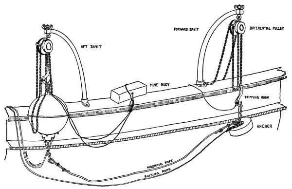
A mousing must be put around the upper hook of the differential block to prevent the block from jumping off the hook when the mine or anchor is tripped. The tripping hook of the differential block on the forward davit is attached to the anchor and it is hoisted and swung outboard clear of the rail. The mine is similarly slung from the after davit by its maneuvering ring or by a rope sling through the latter. Both mine and anchor are lowered as close to the water as conditions will permit. A heaving line is bent onto the free end of the mine cable, generally by means of a clove hitch and two half hitches.
The aft detail now removes or cuts the rope lashings of the coil of the corresponding mine cable. A detail sees that the cable and raising rope are held on the gunwale ready for planting. These should not be allowed to trail in the water. A man stands near the
mine davit ready to throw the mine buoy clear of the planter when the mine is tripped. (Fig. 13 shows the mine and anchor slung for planting and fig. 14 shows the relative position of the various parts in the water. In these figures the cable should be shown as lashed to the mooring rope.)
The distribution box boat should precede the planter to the mine field. The distribution box buoy, to which the anchor rope is fastened by a bowline, to the bight of which the raising rope is secured, is taken aboard at the bow, if the tide is coming in toward the box, and the anchor rope is made fast. The distribution box is then raised by its raising rope and secured in the stern. The boat is thus anchored fore-and- aft, perpendicular to the line of mines, with its bow pointed toward the position of the center mine of the group. If the tide is running out from the box, the buoy should be taken in at the stern, the boat being held in position by the raising rope of the distribution box and then by the multiple cable. The anchor rope is finally made fast in the bow. During the planting of mines a man should always stand ready to slacken away on the anchor rope if necessary.
FIG. 13.—MINE READY FOR PLANTING.
FIG. 14.—MINE PLANTED.
If the buoy for the distribution box is not in place, the cable must be underrun, either from shore or from a buoy planted for this purpose. This is done preferably with a yawl. The cable is raised, taken aboard, and placed over a roller or rowlock in the stern. The cable is then pulled in over the stern and lowered over a roller or rowlock in the bow. If the planter is to underrun cable, a cathead is put in place and a snatch block is lowered by a raising rope secured to a hoisting windlass. The cable is placed in the snatch block and the planter moves forward slowly. When it is desired to transfer the cable to a small boat the snatch block is lowered into the boat and the cable removed.
After the distribution box boat has secured the box in position, the lid is removed and the cable is tested as prescribed on page 44. A signal is then raised to indicate to the planter that the distribution box boat is ready for the planting of mines.
Planting the mines.—If there be a strong tide, the mines should, if possible, be planted at such time that the planter, in going out toward the line of mines, moves against the tide.
The planter moves out and passes close to the distribution box boat, with the latter to port. As it passes slowly by, a heaving line is thrown by a man forward of the beam to the distribution box boat, whose party immediately hauls in the mine cable, bends on another heaving line, and lashes the cable to the boat. It is desirable to have a second heaving line ready in case the first one fails. If the water be rough the cable end is passed to the boat by a launch.
The planter moves forward to the position to be occupied by mine No. 10. If automatic anchors are used, the distance weight is lowered at the command “Lower weight,” given after the cable is secured in the distribution box boat. As the planter approaches this position the command “Get ready” is given. As the forward davit comes abreast of the position of No. 10 mine, the officer in charge of the planting commands “Let go”; the tripping hook of the mine is released first and that of the anchor immediately thereafter. The mine buoy, cable, and raising rope are then thrown overboard.
(Caution. The men operating the tripping hooks must be very careful that they stand back of all cable and rope, so that they may not be caught. All others must stand clear.)
The planter turns so that the stern will be thrown away from the planted mine. When the stern is clear of the mine buoy “All clear” is signaled from the stern.
The planter then executes a sweeping circle to starboard, passes to the rear, and comes up with the distribution box boat to starboard. As it moves by, the free end of mine cable No. 9 is passed to the boat and secured as before. The planter moves ahead to a point 100 feet to the left of mine No. 10, and as it crosses the line, plants mine No. 9, swings off to port, circles and comes up from the rear with the distribution box to port, and so on alternately until all the mines are planted.