covers one of the ARRT-designated content areas, namely physics and instrumentation, patient care, and imaging procedures. However, the categorization of topics is far from clear-cut. For instance, a question regarding the appropriate type and dose of iodinated contrast for a given procedure could just as easily fall under the category of patient care as that of imaging procedures. Since topic categories often overlap, many subjects will appear in more than one section of the book, most likely with a slightly different perspective. Using the example above to illustrate, in the section on patient care, contrast media is covered from a global standpoint and includes such things as its characteristics and types. In the section on imaging procedures, the topic of contrast media arises again, this time in regard to why certain agents are preferred for certain types of procedures.
Having worked as a technologist for over 20 years, I have approached this text with a technologist’s (not a physicist’s or a radiologist’s) perspective. The focus is on caring for patients and creating quality exams, with just enough physics so that everything makes sense. It is apparent from the content specifications of the advanced level CT certification exam that the ARRT shares my philosophy. Seventy percent of the questions contained on the exam relate to exam protocols and patient care.
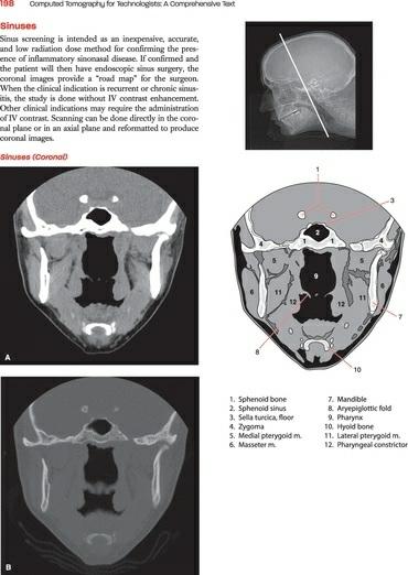
The ability to accurately identify cross-sectional anatomy is an important aspect of the technologist’s job and comprises a significant portion of the ARRT certification exam. The anatomy section included in this text is intended only as an introduction to cross-sectional anatomy; the images included should give the reader an idea of the level of anatomic detail with which the technologist is expected to become familiar. Many excellent texts currently exist that provide a full range of cross-sectional images, should the reader wish to continue their studies.
Many individuals are looking for a “cookbook” of exam protocols. There are two main problems with creating such a cookbook. First, there are no universally accepted protocols that could be considered the standard of care in the field. Protocols are as varied as the professionals that use them, with adjustments made for the type of patient, the type of scanner, and the preferences of the radiologists. The other main barrier to a cookbook approach is that the rapid advancements in the field of radiology make any such document obsolete before the ink dries. With that caveat, in each main anatomic category, I have included a few exam protocols, in many cases ones
that we use at the University of Michigan. These are intended as a frame of reference only with the expectation that protocols must constantly evolve to keep up with new developments in the field.
ADDITIONS
AND UPDATES TO SECOND EDITION
Although advances are continuously being made in CT, the fundamental concepts required for the radiology professional have changed little from the publication of the first edition. However, there have been a number of changes and developments in the field; new data that of sufficient interest and importance have been included in the second edition. The format has been kept essentially intact, as it has proved a successful teaching tool. The new edition retains the simplicity that has made the first edition so popular.
Although CT fundamentals have not changed, enormous strides have been made in the development of multidetector CT (MDCT). These developments greatly boosted equipment sales with virtually all vendors participating in what has been coined the “CT slice wars.” Systems leapt quickly from the first 4-slice scanner to 16-, 32-, 64-, and now 256- and 320slice configurations. Fortunately, a firm understanding of helical scanning principles and the issues related to MDCT will allow technologists to easily adjust their thinking to any number of detectors contained in a particular model of scanner.
New material has been added on dual-energy and dual-source CT systems. Although the concepts are not new, newer technology has overcome previous limitations and allowed these designs to make it into mainstream clinical practice.
As the slice wars plateau and wind down, lowering radiation dose without compromising image quality has moved to the forefront. The increase in media attention regarding radiation dose from CT procedures has fueled the trend. Hence, additional information has been included regarding patient radiation dose. This includes methods to reduce dose, such as adaptive statistical iterative reconstruction techniques, and factors in expanded MDCT that contribute to the dose, such as overranging.
Yet the level of risk to patients associated with radiation is not without
controversy. It seems that the pendulum continues to swing. From the early years of CT in the 1980s when few radiology professionals had even a basic idea of the dose their scanners delivered to the early 2000s when information surfaced concerning the effects of low-dose radiation on atomic bomb survivors who were irradiated as children prompted a heightened concern among healthcare professionals and the public. More recently, the pendulum seems to be moving back to a more moderate position with a number of strong voices in the field questioning the validity and applicability of extrapolating data from atomic bomb survivors to relatively low-dose radiologic studies. To increase the reader’s understanding of this hot-button issue, a summary of the debate has been included in the chapter on radiation dosimetry.
Lois E. Romans, RT, (R)(CT) Michigan Medicine, University of Michigan Ann Arbor, Michigan
User’s Guide
This User’s Guide introduces you to the helpful features of Computed Tomography for Technologists: A Comprehensive Text, second edition, that enable you to quickly master new concepts and put your new skills into practice.
Chapter features to increase understanding and enhance retention of the material include:
Key terms help you focus on the most important concepts as you progress through the chapter.
Key Concepts Boxes present important information for readers to remember (exam material).
Clinical Application Boxes use real-life scenarios to illustrate and explain concepts.
Review Questions at the end of each chapter promote a deeper understanding of fundamental concepts by encouraging analysis and application of information presented.
Recommended Reading or References provide the opportunity to expand on the knowledge gained from the chapter.
Examples of Exam Protocols are included for each major anatomical area.
CT Cross-Sectional Slices accompanied by shaded diagrams and a reference image are featured in the Cross-Sectional Anatomy section of the book.
Glossary in the back of the book defines all the key terms used throughout the text.
Student Resources
The online student resource center at http://thePoint.lww.com/RomansCT reinforces what you learn in the text. Student resources include full text online, PowerPoint slides, and the protocol tables from the book containing localizer images to guide technologists in setting the scan range of each specific study. See the inside front cover for details on how to access these resources.
Instructor Resources
The online instructor resources available for use with Computed Tomography for Technologists: A Comprehensive Text, second edition, include PowerPoints, an image bank, and situational judgment questions.
Reviewers
The publisher, author, and editors gratefully acknowledge the valuable contributions made by the following professionals who reviewed this text:
Matthew G. Aagesen, MD
Musculoskeletal Fellow
University of Michigan Health System
Ann Arbor, Michigan
Sulaiman D. Aldoohan, PhD, DABR
Assistant Professor
Department of Radiological Sciences
College of Medicine
University of Oklahoma Health Sciences Center
Oklahoma City, Oklahoma
Jonathan Baldwin, MS, CNMT, RT(CT)
Assistant Professor and Clinical Coordinator Nuclear Medicine
Statistical and Research Design Consultant
College of Allied Health
University of Oklahoma Health Sciences Center
Oklahoma City, Oklahoma
Jeff L. Berry, MS, RT (R) (CT)
Associate Professor, Radiography Program Director
Director of Advanced Imaging and Continuing Education
College of Allied Health
University of Oklahoma Health Sciences Center
Oklahoma City, Oklahoma
Jonathan R. Dillman, MD
Abdominal Radiology Fellow
University of Michigan Health System
Ann Arbor, Michigan
Lois Doody, Med
Instructor
Medical Radiography Program
BCIT
Vancouver, British Columbia
Susan K. Dumler, MS, RT (R)(M)(CT)(MR)
Lecturer
Fort Hays State University
Lecturer and Clinical Coordinator
Department of Allied Health
Fort Hays State University
Hays, Kansas
John W. Eichinger, MSRS, (R)(CT) ARRT
Program Director-Radiologic Technology
Technical College of the LowCountry
Beaufort, South Carolina
James H. Ellis, MD, FACR
Professor of Radiology
University of Michigan Health System
Ann Arbor, Michigan
Frances Gilman, MS, RT, R, CT, MR, CV, ARRT
Assistant Professor and Chair
Department of Radiologic Sciences
Thomas Jefferson University
Philadelphia, Pennsylvania
Ella A. Kazerooni, MD, FACR
Professor of Radiology
Director, Cardiothoracic Radiology
University of Michigan Health System
Ann Arbor, Michigan
Kathleen Lowe, RTR, RTMR, BappSc
Faculty Diagnostic Imaging
Dawson College
Westmount, Quebec, Canada
Leanna B. Neubrander, BS, RT (R) (CT)
Instructor, Department of Radiologic Sciences
Florida Hospital College of Health Sciences
Orlando, Florida
Saabry Osmany, MDDr.
Department of Nuclear Medicine and PET
Singapore General Hospital
Singapore
Deena Slockett, MBA, RT (R), (M)
Associate Professor, FHCHS
Program Coordinator
Department of Radiologic Sciences
Orlando, Florida
Suzette Thomas-Rodriguez, BS (Medical Imaging),
ARRT(R) (CT) (MRI)
Senior Lecturer
Department of Radiological Sciences
College of Science Technology and Applied Arts of Trinidad & Tobago
Port-of-Spain, Trinidad
Amit Vyas, MD
Neuroradiology Fellow
University of Michigan Health System
Ann Arbor, Michigan
Bettye G. Wilson, MAEd, ARRT(R) (CT), RDMS, FASRT
Associate Professor of Medical Imaging and Therapy
School of Health Professions
University of Alabama at Birmingham Birmingham, Alabama
Acknowledgments
I cannot overstate the contributions of Dr. James Ellis from the University of Michigan Radiology Department. I routinely handed him a sow’s ear and he unfailingly amazed me by returning a silk purse. His meticulous review went far beyond my wildest expectation. His thoughtful suggestions and patient guidance improved every aspect of the manuscript. The second edition greatly benefited by the expertise of Jeff Berry, Radiography Program Director, University of Oklahoma Health Sciences Center. His extensive educational experience ensured that each concept presented was consumable by the typical student and that new developments in the field were included. Special thanks to Dr. Saabry Osmany for his help in editing the chapter on PET/CT and for supplying PET/CT images. I gratefully acknowledge the expertise of diagnostic physicists Emmanuel Christodoulou and Mitch Goodsitt, who helped me make sense of the complex data available on radiation dose. Thanks to my dear friend and fellow technologist Renee Maas for support, encouragement, and willingness to be my model when I needed photographs of a patient in a scanner. Thanks to 3D lab technologist Melissa Muck, who supplied outstanding images for the chapter on postprocessing techniques. My gratitude to the many CT technologists at the University of Michigan that helped me to find just the right images: Ronnie Williams, Ricky Higa, John Rowe, and Eric Wizauer. Thanks to Lisa Modelski for keeping me organized. Finally, my thanks to the exceptionally talented artist, Jonathan Dimes, who listened to my ramblings and somehow produced exactly what was in my mind’s eye.
Table of Contents
Preface
User’s Guide
Reviewers
Acknowledgments
SECTION I: Physics and Instrumentation
CHAPTER 1 Basic Principles of CT
CHAPTER 2 Data Acquisition
CHAPTER 3 Image Reconstruction
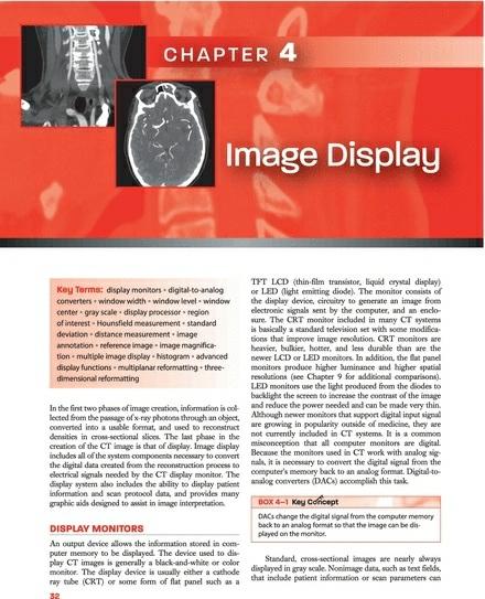
CHAPTER 4 Image Display
CHAPTER 5 Methods of Data Acquisition
CHAPTER 6 Image Quality
CHAPTER 7 Quality Assurance
CHAPTER 8 Post-processing
CHAPTER 9 Data Management
SECTION II: Patient Care
CHAPTER 10 Patient Communication
CHAPTER 11 Patient Preparation
CHAPTER 12 Contrast Agents
CHAPTER 13 Injection Techniques
CHAPTER 14 Radiation Dosimetry in CT
SECTION III: Cross-Sectional Anatomy
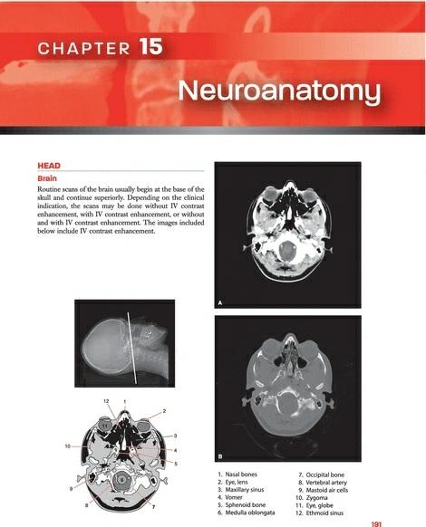
CHAPTER 15 Neuroanatomy
CHAPTER 16 Thoracic Anatomy
CHAPTER 17 Abdominopelvic Anatomy
CHAPTER 18 Musculoskeletal Anatomy
SECTION IV: Imaging Procedures and Protocols
CHAPTER 19 Neurologic Imaging Procedures
CHAPTER 20 Thoracic Imaging Procedures
CHAPTER 21 Abdomen and Pelvis Imaging Procedures
CHAPTER 22 Musculoskeletal Imaging Procedures
CHAPTER 23 Interventional CT and CT Fluoroscopy
CHAPTER 24 PET/CT Fusion Imaging
Glossary
Index
SECTION I Physics and Instrumentation
Chapter 1 • Basic Principles of CT
Chapter 2 • Data Acquisition
Chapter 3 • Image Reconstruction
Chapter 4 • Image Display
Chapter 5 • Methods of Data Acquisition
Chapter 6 • Image Quality
Chapter 7 • Quality Assurance
Chapter 8 • Post-processing
Chapter 9 • Data Management
The cornerstone of a technologist’s responsibility is to produce consistently high-quality examinations while ensuring the safety and well-being of patients. Educational content for the CT technologist must be evaluated with that goal in mind. It is not necessary that a technologist’s understanding of CT physics rival that of a medical physicist. I believe in the concept expressed in the phrase “You don’t have to know how to build a car to be a good driver.” However, understanding the physical aspects of CT technology allows the technologist to identify deficiencies in images and to take appropriate corrective actions, just as understanding the basics of auto mechanics will help a driver know whether the car simply needs gas or
whether a trip to the repair shop is warranted. The physics presented in this section will allow technologists to move past the rote learning of examination protocols and allow them to grasp why we do what we do. They will understand the connection between the choices they make selecting scan parameters and the radiation dose delivered to the patient. It will not prepare them for a career as a physicist. For those readers who desire a more in-depth understanding of CT physics, there are many textbooks from which to choose.
Conventional radiographs depict a three-dimensional object as a twodimensional image. This results in overlying tissues being superimposed on the image, a major limitation of conventional radiography. Computed tomography (CT) overcomes this problem by scanning thin sections of the body with a narrow x-ray beam that rotates around the body, producing images of each cross section. Another limitation of the conventional radiograph is its inability to distinguish between two tissues with similar densities. The unique physics of CT allow for the differentiation between
tissues of similar densities.
The main advantages of CT over conventional radiography are in the elimination of superimposed structures, the ability to differentiate small differences in density of anatomic structures and abnormalities, and the superior quality of the images.
TERMINOLOGY
The word tomography has as its root tomo, meaning to cut, section, or layer from the Greek tomos (a cutting). In the case of CT, a sophisticated computerized method is used to obtain data and transform them into “cuts,” or cross-sectional slices of the human body.
The first scanners were limited in the ways in which these cuts could be performed. All early scanners produced axial cuts; that is, slices looked like the rings of a tree visualized in the cut edge of a log. Therefore, it was common to refer to older scanning systems as computerized axial tomography, hence the common acronym, CAT scan.
Newer model scanners offer options in more than just the transverse plane. Therefore, the word “axial” has been dropped from the name of current CT systems. If the old acronym CAT is used, it now represents the phrase computer-assisted tomography.
The historic evolution of CT, although interesting, is beyond the scope of this text. However, for clarity, a few key elements in the development of CT are mentioned here.
Although all CT manufacturers began with the same basic form, each attempted to set their scanners apart in the marketplace by adding features and functionality to the existing technology. As each feature was developed, each manufacturer gave the feature a name. For this reason, the same feature may have a variety of different names, depending on the manufacturer. For example, the preliminary image each scanner produces may be referred to as a “topogram” (Siemens), “scout” (GE Healthcare), or “scanogram” (Toshiba). Another well-known example is a method of scanning that, generically, is referred to as continuous acquisition scanning; this method can also be called “spiral” (Siemens), “helical” (GE Healthcare), or “isotropic” (Toshiba) scanning. In many cases, the trade name of the function is more widely recognized than is the generic term. This text refers to each function
by the name that best describes it or by the term that is most widely used. Once one understands what each operation accomplishes, switching terms to accommodate scanners is simple.
CT image quality is typically evaluated using a number of criteria:
Spatial resolution describes the ability of a system to define small objects distinctly.
Low-contrast resolution refers to the ability of a system to differentiate, on the image, objects with similar densities.
Temporal resolution refers to the speed at which the data can be acquired. This speed is particularly important to reduce or eliminate artifacts that result from object motion, such as those commonly seen when imaging the heart.
These aspects of image quality will be explained more fully in Chapter 6.
COMPUTED TOMOGRAPHY DEFINED
Computed tomography uses a computer to process information collected from the passage of x-ray beams through an area of anatomy. The images created are cross-sectional. To visualize CT, the often-used loaf of bread analogy is useful. If the patient’s body is imagined to be a loaf of bread, each CT slice correlates to a slice of the bread. The crust of the bread is analogous to the skin of the patient’s body; the white portion of the bread, the patient’s internal organs.
The individual CT slice shows only the parts of the anatomy imaged at a particular level. For example, a scan taken at the level of the sternum would show portions of lung, mediastinum, and ribs but would not show portions of the kidneys and bladder. CT requires a firm knowledge of anatomy, in particular the understanding of the location of each organ relative to others.
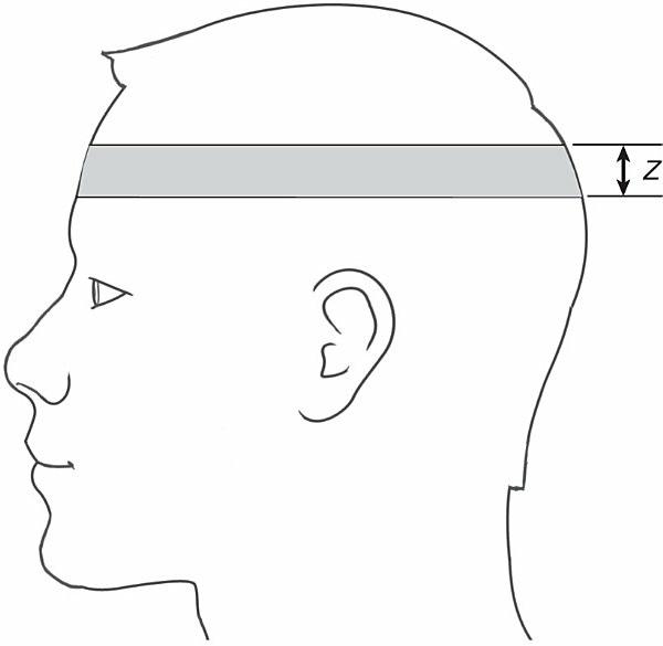
Each CT slice represents a specific plane in the patient’s body. The thickness of the plane is referred to as the Z axis. The Z axis determines the thickness of the slices (Fig. 1-1). The operator selects the thickness of the slice from the choices available on the specific scanner. Selecting a slice thickness limits the x-ray beam so that it passes only through this volume; hence, scatter radiation and superimposition of other structures are greatly diminished. Limiting the x-ray beam in this manner is accomplished by mechanical hardware that resembles small shutters, called collimators, which
adjust the opening based on the operator’s selection.
FIGURE 1-1 The thickness of the cross-sectional slice is referred to as its Z axis.
The data that form the CT slice are further sectioned into elements: width is indicated by X, while height is indicated by Y (Fig. 1-2). Each one of these two-dimensional squares is a pixel (picture element). A composite of thousands of pixels creates the CT image that displays on the CT monitor. If the Z axis is taken into account, the result is a cube, rather than a square. This cube is referred to as a voxel (volume element).
FIGURE 1-2 The data that form the CT slice are sectioned into elements.
A matrix is the grid formed from the rows and columns of pixels. In CT, the most common matrix size is 512. This size translates to 512 rows of pixels down and 512 columns of pixels across. The total number of pixels in a matrix is the product of the number of rows and the number of columns, in this case 512 × 512 (262,144). Because the outside perimeter of the square is held constant, a larger matrix size (i.e., 1,024 as opposed to 512) will contain smaller individual pixels. Each pixel contains information that the system
obtains from scanning.
BEAM ATTENUATION
The structures in a CT image are represented by varying shades of gray. The creation of these shades of gray is based on basic radiation principles. An xray beam consists of bundles of energy known as photons. These photons may pass through or be redirected (i.e., scattered) by a structure. A third option is that the photons may be absorbed by a given structure in varying amounts, depending on the strength (average photon energy) of the x-ray beam and the characteristics of the structure in its path. The degree to which a beam is reduced is a phenomenon referred to as attenuation.
BOX 1-1 Key Concept
The degree to which an x-ray beam is reduced by an object is referred to as attenuation.
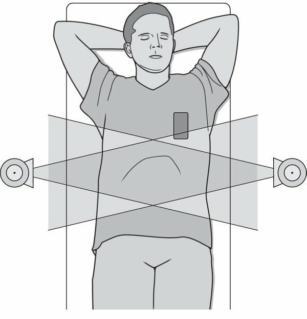
In conventional radiography, the x-ray beam passes through the patient’s body and activates an image receptor. Similarly, in CT, the x-ray beam passes through the patient’s body and is recorded by the detectors. The computer then processes this information to create the CT image. In both cases, the quantities of x-ray photons that pass through the body determine the shades of gray on the image.
By convention, x-ray photons that pass through objects unimpeded are represented by a black area on the image. These areas on the image are commonly referred to as having low attenuation. Conversely, an x-ray beam that is completely absorbed by an object cannot be detected; the place on the image is white. An object that has the ability to absorb much of the x-ray beam is often referred to as having high attenuation. Areas of intermediate attenuations are represented by various shades of gray.
The number of the photons that interact depends on the thickness, density, and atomic number of the object. Density can be defined as the mass of a substance per unit volume. More simply, density is the degree to which