Chapter 6: Designing with Field Programmable Gate Arrays
6.1 (a) 4 Cells, if N is used as the clock enable. When N = 1 then
X0 + = S' D0 + S X1 (3 variable function) (two 3 variable functions
X1 + = S' D1 + S X2 (3 variable function) will fit into one cell)
If the clock enable is not used each bit requires a separate cell: 8 cells total.
X0 + = N S' D0 + N S X1 + N' X0 (5 variable function)
(b)
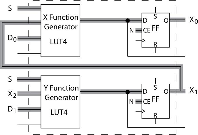
(c) X function generator output = X0 + = S' D0 + S X1
Y function generator output = X1 + = S' D1 + S X2
6.2 (a) QA0 + = En (Ld U + Ld' QA0') + En' QA0 = En (X) + En' QA0
QA1 + = En (Ld V + Ld' (QA0 QA1) + En' QA1 = En (Y) + En' QA1
(b)
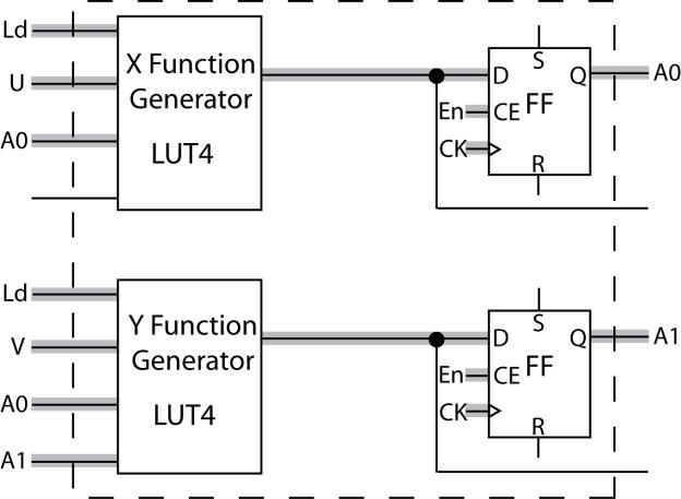
X = Ld U + Ld' QA0 ' Y = Ld V + Ld' (QA0 QA1)
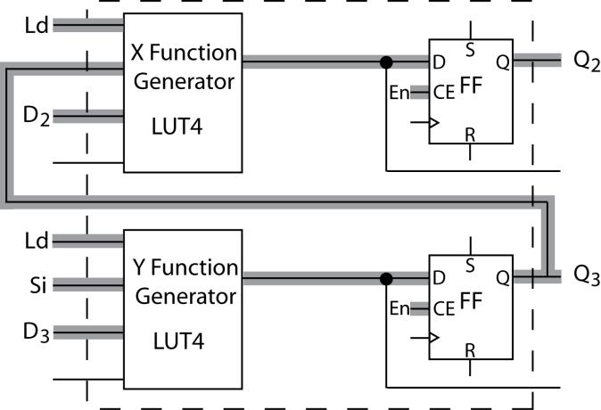
6.3 (a) Q2 + = EN' Q2 + EN (Ld D2 + Ld' Q3)
Q1 + = EN' Q1 + EN (Ld D1 + Ld' Q2)
Q0 + = EN' Q0 + EN (Ld D0 + Ld' Q1)
(b) Two cells
(c) Y = Ld D3 + Ld' Si X = Ld D2 + Ld' Q3
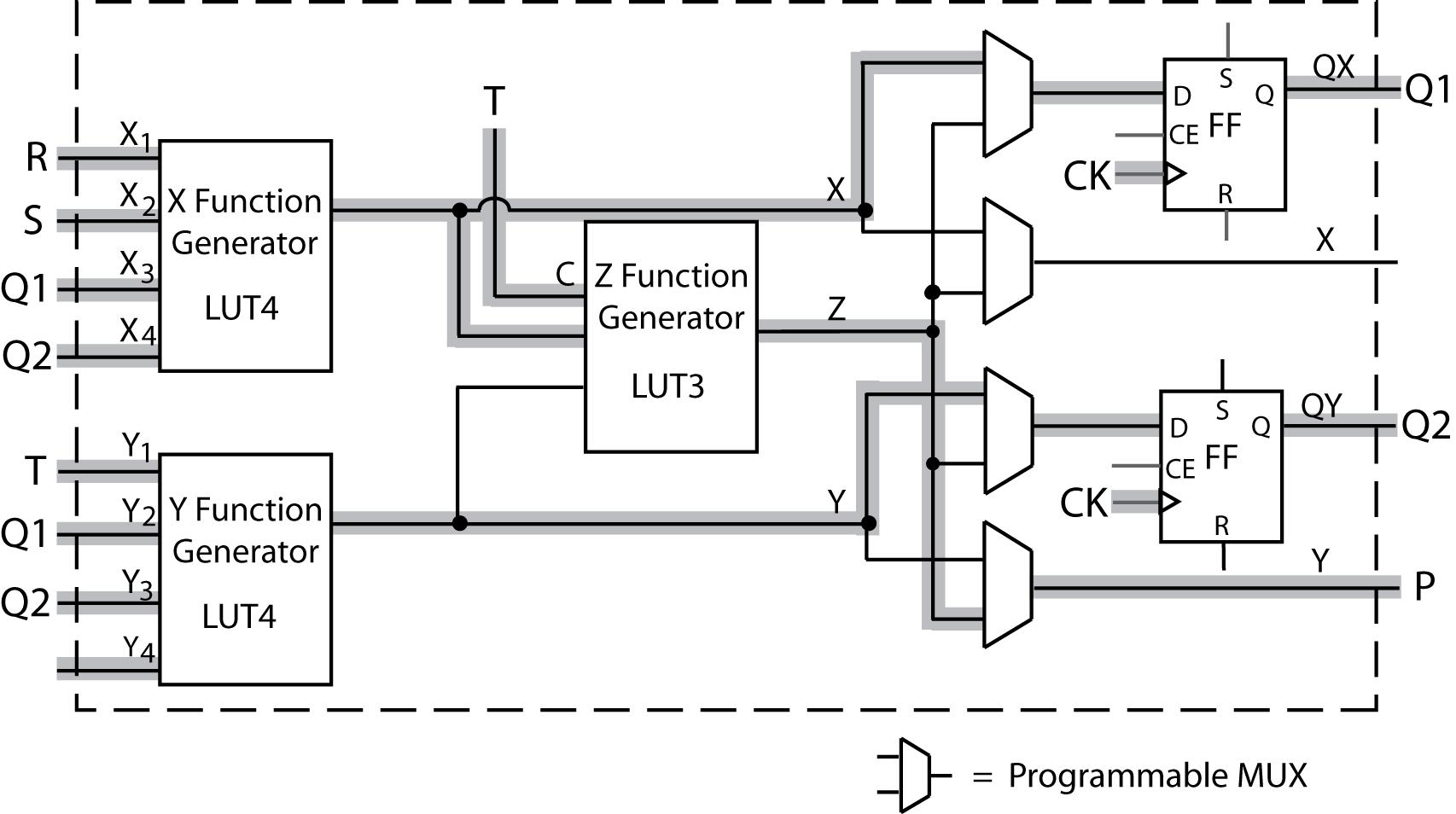
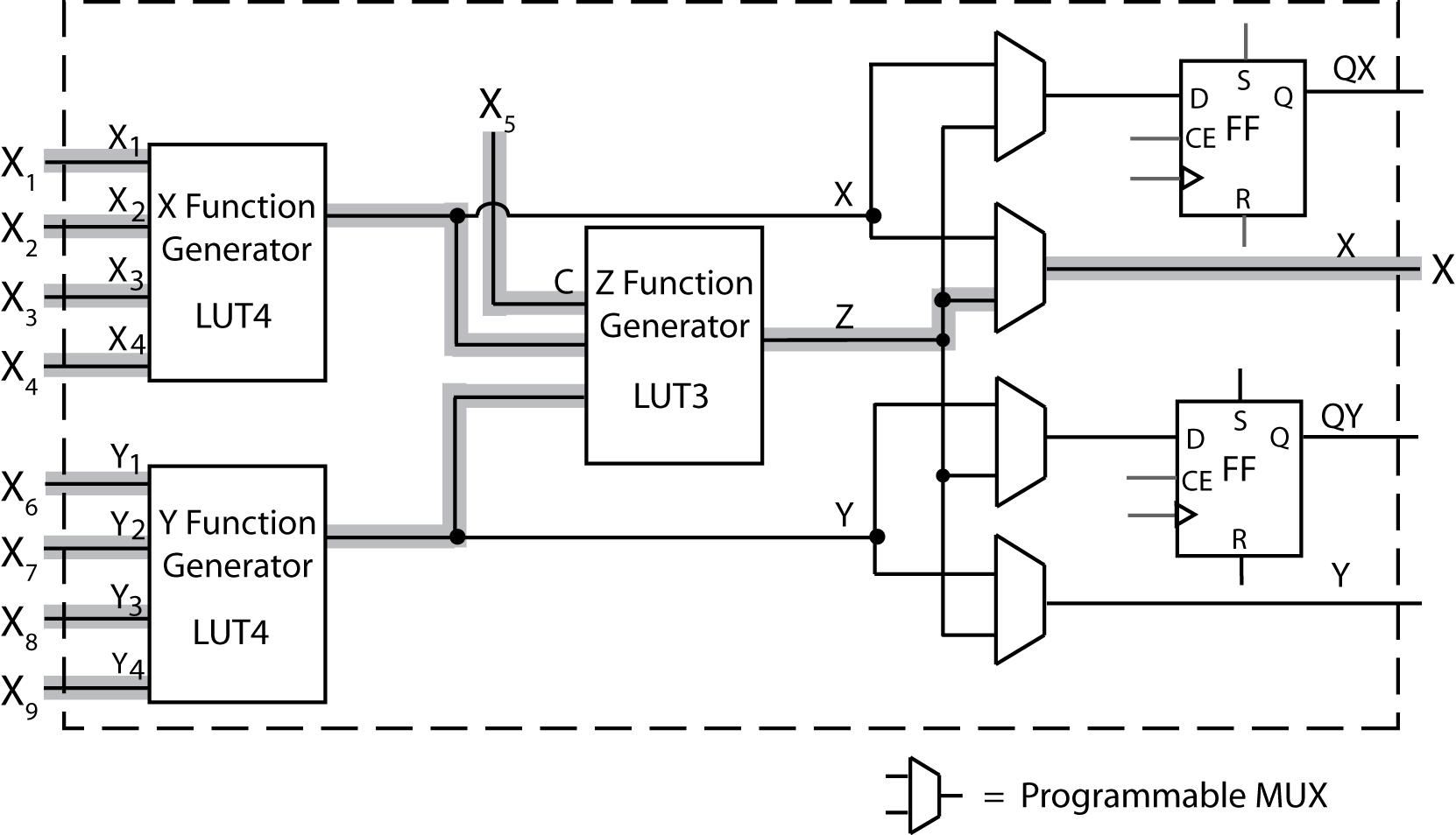
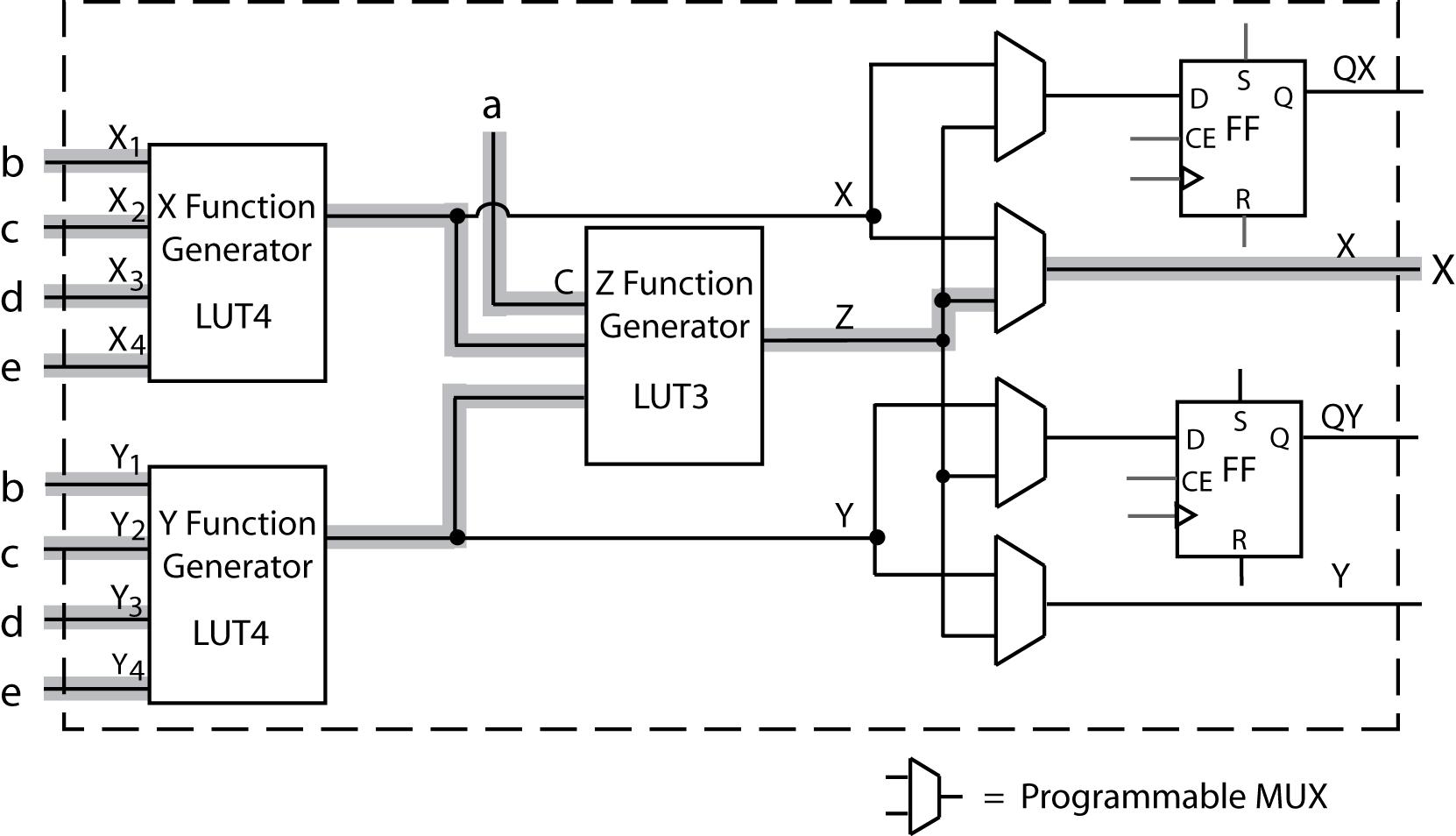
6.4 (a) The next state equation of Q1 can be implemented using the X function generator with the inputs R, S, Q1, and Q2. The next state equation of Q2 can be implemented using the Y function generator with the inputs T, Q1, and Q2. The output P can be implemented using the Z function generator with the inputs T (C input) and the X function generator.
(b)
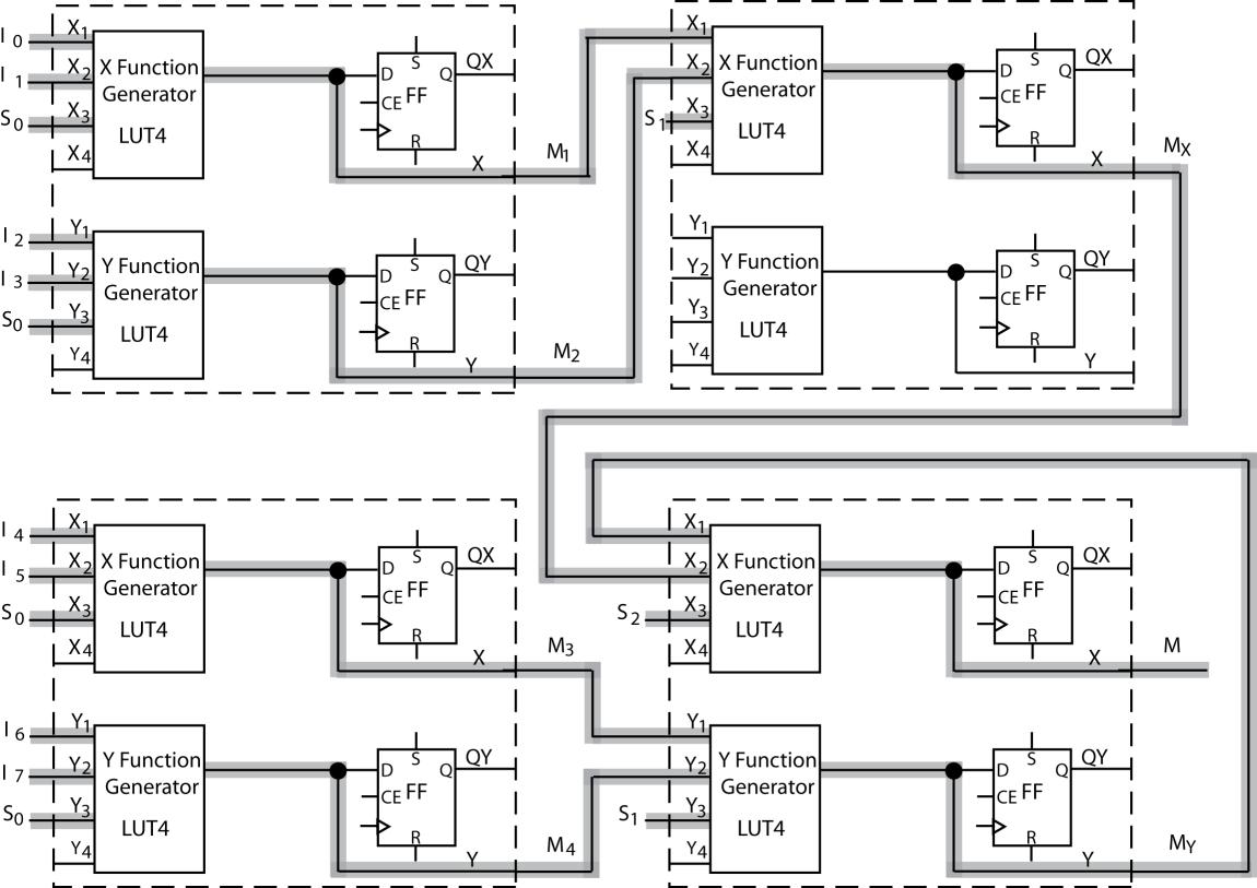
6.5 (a) M =
The 8-to-1 MUX can be decomposed into seven 2-to-1 MUXes, and implemented in four Figure 6-1(a) logic blocks.
The X and Y functions for each block each implement one 2-to-1 mux as labeled:
(b) Three 2-to-1 MUXes (or a 4-to-1 mux) can be implemented in each Figure 6-3 logic block. In total, three blocks are required to implement seven 2-to-1 MUXes. The X, Y, and Z function generators for each block implement a 2-to-1 MUX as labeled:
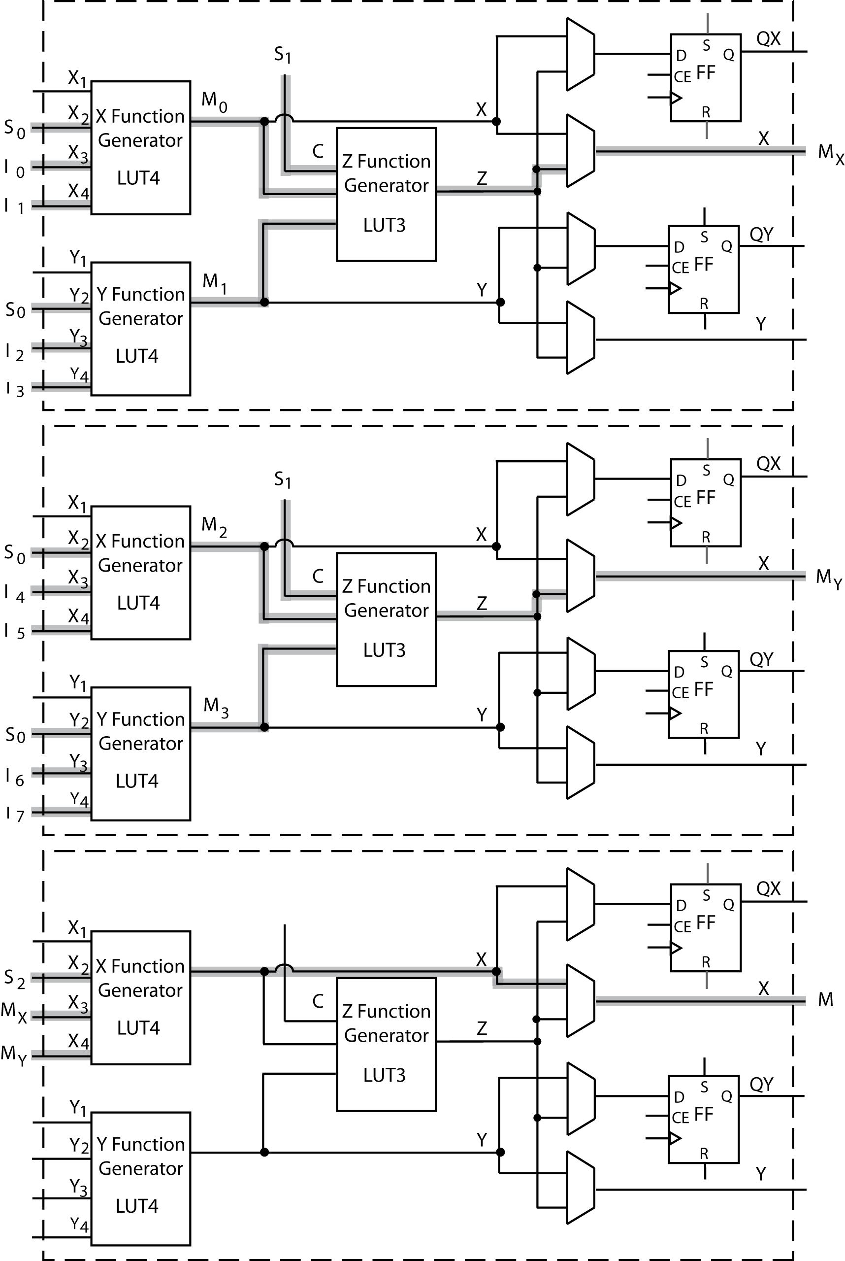
(c) Each function generator used implements a 2-to-1 mux, and has the same LUT contents: 0, 1, 0, 1, 0, 0, 1, 1, 0, 1, 0, 1, 0, 0, 1, 1
(d) Each function generator used implements a 2-to-1 mux X and Y LUT4s have 0, 0, 0, 0, 1, 1, 0, 0, 0, 0, 1, 1, 1, 1, 1, 1
Z LUT3s have 0, 0, 1, 1, 0, 1, 0, 1 (Consider C as MSB, Y as LSB)
6.6 (a) module Figure6_1a(X_in, Y_in, clk, CE, Qx, Qy, X, Y, XLUT, YLUT); input [1:4] X_in, Y_in; input clk, CE; input [0:15] XLUT, YLUT; inout X, Y; output Qx, Qy;
reg Qx, Qy; wire [1:4] X_Index, Y_Index;
initial begin
Qx = 1'b0; Qy = 1'b0; end
assign X_Index = {X_in[4], X_in[3], X_in[2], X_in[1]}; assign Y_Index = {Y_in[4], Y_in[3], Y_in[2], Y_in[1]}; assign X = XLUT[X_Index]; assign Y = YLUT[Y_Index];
always @(posedge clk) begin if(CE == 1'b1) begin Qx <= X; Qy <= Y; end end endmodule
(b) module LUT_Mux(I0, I1, I2, I3, S0, S1, M); input I0, I1, I2, I3, S0, S1; output M;
wire Qx1, Qy1, Qx2, Qy2, MM; wire [1:4] in1, in2, in3; wire M1, M2, Mout;
assign in1 = {I0, I1, S0, 1'b0}; assign in2 = {I2, I3, S0, 1'b0}; assign in3 = {M1, M2, S1, 1'b0}; assign M = Mout;
Figure6_1a B0(in1, in2,1'b0, 1'b0, Qx1, Qy1, M1, M2, 16'b0101001101010011, 16'b0101001101010011); Figure6_1a B1(in3, 4'b0000, 1'b0, 1'b0, Qx2, Qy2, Mout, MM, 16'b0101001101010011, 16'b0000000000000000); endmodule
6.7 (a) module Figure6_3(X_in, Y_in, clk, CE, C, Qx, Qy, X, Y, XLUT, YLUT, ZLUT, SA, SB, SC, SD); input [1:4] X_in, Y_in; input clk, CE, C; input [0:15] XLUT, YLUT; input [0:7] ZLUT; input SA, SB, SC, SD; output X, Y; output reg Qx, Qy;
initial begin
Qx = 1'b0; Qy = 1'b0; end
wire [1:4] X_Index, Y_Index; wire [1:3] Z_Index; wire X_int, Y_int, Z_int; wire MuxA, MuxB, MuxC, MuxD;
assign X_Index = {X_in[4], X_in[3], X_in[2], X_in[1]}; assign Y_Index = {Y_in[4], Y_in[3], Y_in[2], Y_in[1]}; assign Z_Index = {Y_int, X_int, C}; assign X_int = XLUT[X_Index]; assign Y_int = YLUT[Y_Index]; assign Z_int = ZLUT[Z_Index];
assign MuxA = (SA == 1'b0)? X_int : Z_int; assign MuxB = (SB == 1'b0)? X_int : Z_int; assign MuxC = (SC == 1'b0)? Y_int : Z_int; assign MuxD = (SD == 1'b0)? Y_int : Z_int; assign X = MuxB; assign Y = MuxD; always @(posedge clk) begin if(CE == 1'b1) begin Qx <= MuxA; Qy <= MuxC; end end endmodule
(b) module Code_Converter(X, clk, Z); input X, clk; output Z;
wire Q1, Q2, Q3, Zout; wire [3:0] D_in; wire T1, T2, T3, T4; assign in = {X, Q1, Q2, Q3}; assign Z = Zout;
Figure6_3 B0(D_in, D_in, clk, 1'b1, 1'b0, Q3, Q2, T1, T2, 16'b0001111111000000, 16'b0110000001000000, 8'b00000000, 1'b0, 1'b0, 1'b0, 1'b0);
Figure6_3 B1(D_in, D_in, clk, 1'b1, 1'b0, Q1, T3, T4, Zout, 16'b1010001110000000, 16'b1010010110011000, 8'b00000000, 1'b0, 1'b0, 1'b0, 1'b0); endmodule
6.8 (a) A 4-to-16 decoder requires 16 outputs, and each function needs no more than 4-variables. 8 Figure 6-1 (a) logic blocks are required.
(b) X-Function LUT: 1, 0, 0, 0, 0, 0, 0, 0, 0, 0, 0, 0, 0, 0, 0
Y-Function LUT: 0, 1, 0, 0, 0, 0, 0, 0, 0, 0, 0, 0, 0, 0, 0
6.9 (a) 4 logic blocks are required, 8 LUT4’s (See Figure 3-6 for truth table).
a = n7 + n6
b1 = n5'n4'
b = n7 + n6
c1 = n5
c
d
6.10 Expanding F around X6 results in 4 variable functions which can be realized using one function generator each. F
For block one: X LUT has inputs
'. Y LUT has inputs X
, X3, X4, and X5 and realizes F2 =
For block two: X LUT has the outputs of block one’s X LUT (F1) and Y LUT (F2), X6, and X7 as inputs. The X LUT realizes F = X6 (F1) + X6' (G1) + X7. The Y LUT is unused.
6.11 Expanding Q+ around U Q results in 4 variable equations which can be realized using one function generator each.
Q+ = U Q (V' W + X' Y + V W') + U' Q' (V X' Y' + V' Y + X Y + V' X)
Q+ = U Q (Xfunc) + U' Q'(Yfunc)
Mark connections in a manner similar to Problem 6.1’s solution.
For block one: X LUT has inputs V, W, X, and Y and realizes V' W + X' Y + V W' Y LUT has inputs V, X, and Y and realizes V X' Y' + V' Y + X Y + V' X
For block two: X LUT has U, Q, and block one’s Xfunc and Yfunc as inputs and realizes Q+ = U Q (Xfunc) + U' Q'(Yfunc)
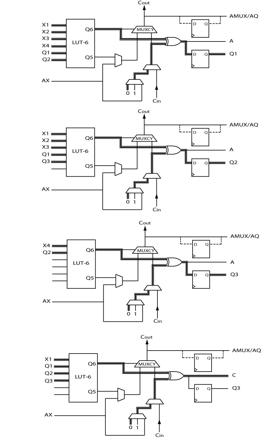
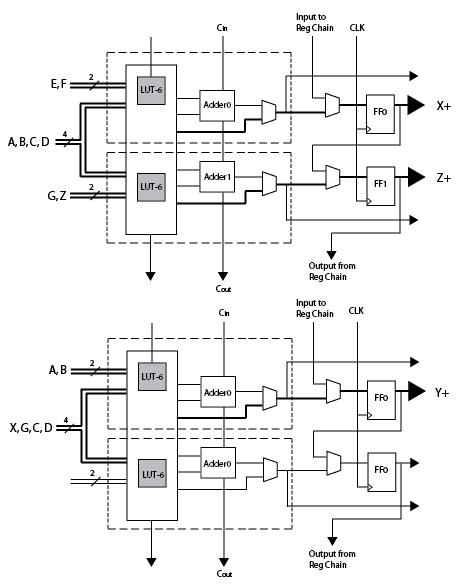
6.12 To realize the next-state equations, we need to use at least four Kintex logic slices (Figure 6-13). One Kintex logic slice is ¼ CLB. Therefore, only 1 CLB is needed.
6.13 One cell. Expanding around X5 results in 4 variable equations which can be realized using one function generator each and X5 can be used as the C input.
Implement internal logic cell connections in a manner similar to Problem 6.12 Solution with U, V, W, and X as inputs to the X-function generator, T, V, W, and X as inputs to the Y-function generator and Y as the C input.
(b) The original equation can be implemented as follows:
Block 1:X-LUT has inputs U, V, W, X and realizes V W' X + U' V' W
Y-LUT has inputs T, V, W, X and realizes V W' X + T V' W
Block 2:X-LUT has Y and Block 1’s Xfunc and Yfunc as inputs and realizes Z = Y (Xfunc) + Y' (Yfunc)
Y-LUT is unused
6.16 F = X6 (X
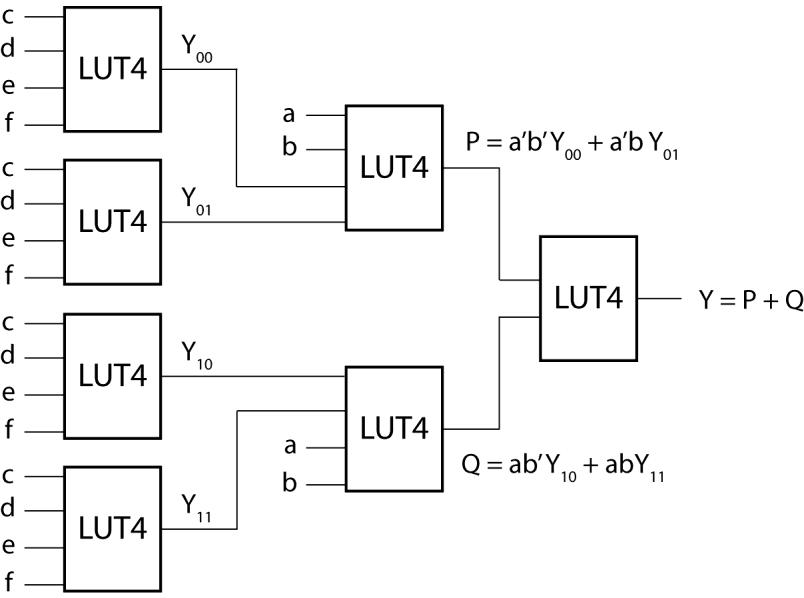
6.17 Y = a'b'Y00 + a'bY01 + ab'Y10 + abY11
Y00 = Ya=0,b=0 = cde'f + c'def
Y01 = Ya=0,b=1 = cde'f + cdef ' + c'de'f
Y10 = Ya=1,b=0 = cde'f + cd 'ef '
Y11 = Ya=1,b=1 = cde + cde'f + cdef ' + cd 'e'f
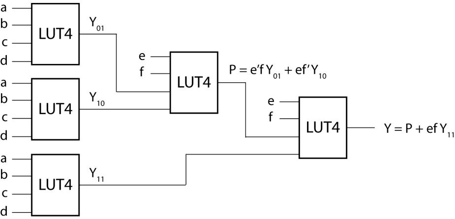
6.18 Y = e'f ' Y00 + e'f Y01 + ef ' Y10 + efY11
Y00 = 0
Y01 = abcd
Y10 = a' bc'd ' + b'c'
Y11 = ab'cd + a'bc'd'
6.19 (a) Y = a' (bc'd'e + b'c'e) + a (b'cd'e + b'c'e + bcde) = a' (Y1) + a (Y2)
Y1 = bc'd'e + b'c'e
Y2 = b'cd'e + b'c'e + bcde
(b)
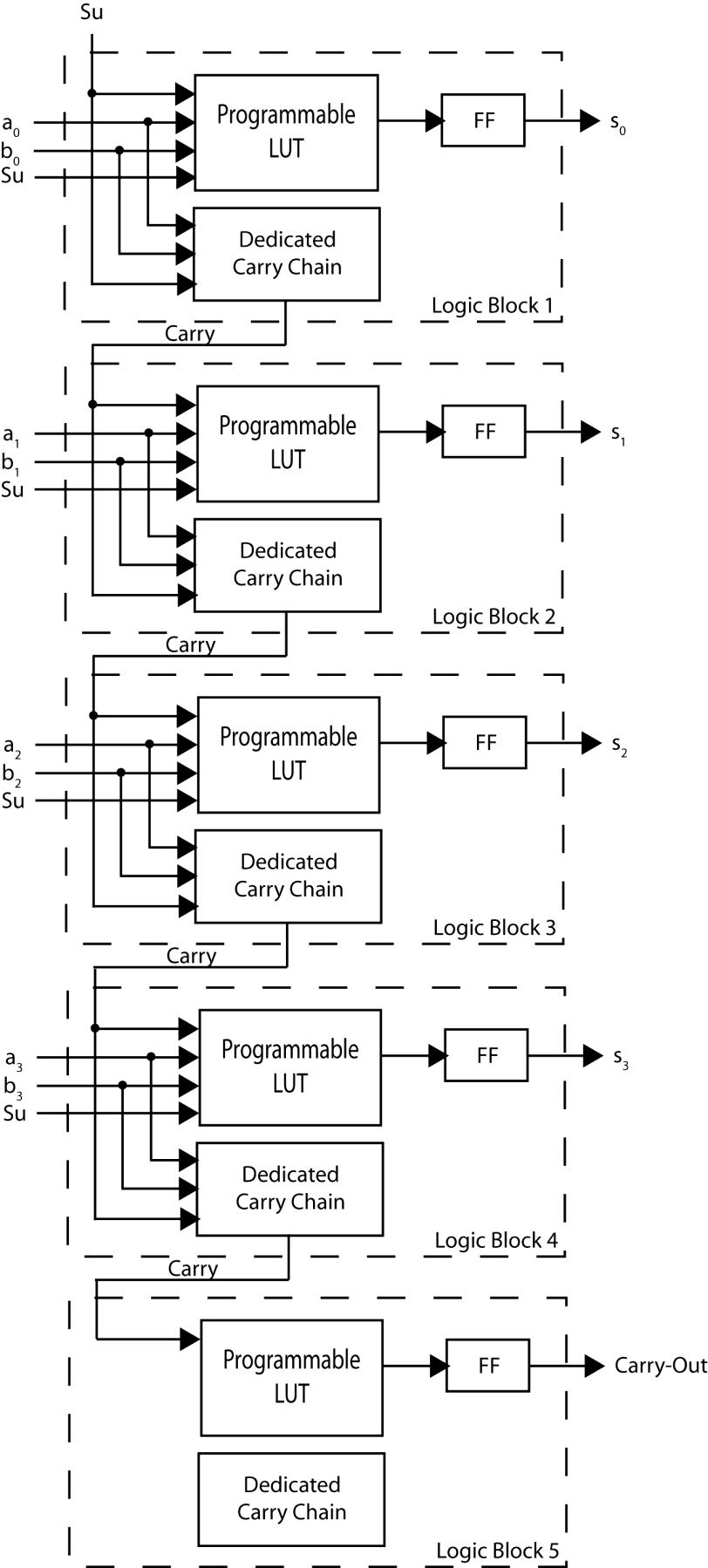
6.20 (a) Eight LUTs are required. Each bit of the adder requires one LUT to generate the sum and one LUT to generate the carry-out.
(b) Four LUT4s are required. Each bit of the adder requires one LUT4 to generate the sum. Dedicated carry chain logic generates the carry-out.
(c) When Su is 1, the circuit should add a to the 2’s complement of b by inverting each bit of b and setting bit 0’s Cin to.
Each bit will have the same output function: