Cross section
in direction Berlin
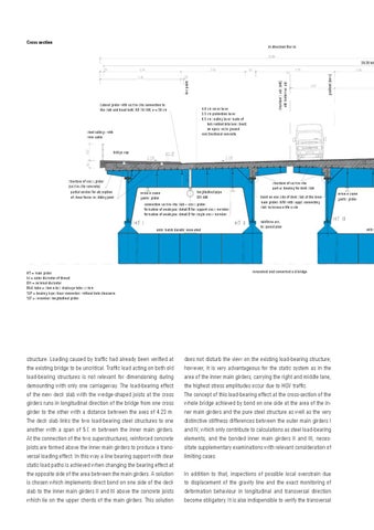
Lateral girder with cast in-situ connection to the slab and head bolts KD 10-100; a = 50 cm
4.0 cm cover layer 3.5 cm protection layer 0.5 cm sealing layer made of hot-welded bitumen sheets on epoxy resin ground constructional concrete
steel railings with wire cable
gradient (new)
structure’s axis (old) old motorway axis
low point
39.39 tot
bridge cap
structure of cross-girder (cast in-situ concrete) partial anchor for absorption of shear forces in sliding joint
remove crane gantry girder
longitudinal pipe DN 400
connection cast in-situ slab – cross-girder formation of analogous detail B for support cross-member formation of analogous detail D for single cross-member
entry hatch durably renovated
HT = main girder M = outer diameter of thread DN = nominal diameter BML tube = sleeve-less drainage tube system SLP = bearing type shear connectors without hole clearance SLT = secondary longitudinal girder
structure. Loading caused by traffic had already been verified at the existing bridge to be uncritical. Traffic load acting on both old load-bearing structures is not relevant for dimensioning during demounting with only one carriageway. The load-bearing effect of the new deck slab with the wedge-shaped joists at the cross girders runs in longitudinal direction of the bridge from one cross girder to the other with a distance between the axes of 4.23 m. The deck slab links the two load-bearing steel structures to one another with a span of 5.0 m between the inner main girders. At the connection of the two superstructures, reinforced concrete joists are formed above the inner main girders to produce a transversal loading effect. In this way a line bearing support with clear static load paths is achieved when changing the bearing effect at the opposite side of the area between the main girders. A solution is chosen which implements direct bond on one side of the deck slab to the inner main girders II and III above the concrete joists which lie on the upper chords of the main girders. This solution
structure of cast in-situ part as bearing for deck slab bond on one side of deck slab at the inner main girders II/III with suppl. connecting slats to increase life cycle reinforce acc. to special plan
renovated and converted old bridge
does not disturb the view on the existing load-bearing structure; however, it is very advantageous for the static system as in the area of the inner main girders, carrying the right and middle lane, the highest stress amplitudes occur due to HGV traffic. The concept of this load-bearing effect at the cross-section of the whole bridge achieved by bond on one side at the area of the inner main girders and the pure steel structure as well as the very distinctive stiffness differences between the outer main girders I and IV, which only contribute to calculations as steel load-bearing elements, and the bonded inner main girders II and III, necessitate supplementary examinations with relevant consideration of limiting cases. In addition to that, inspections of possible local overstrain due to displacement of the gravity line and the exact monitoring of deformation behaviour in longitudinal and transversal direction become obligatory. It is also indispensible to verify the transversal
remove crane gantry girder
entry