Roofing underlay membranes
General functions and background information
Requirements for technical characteristics and durability
Description and comparison of current membrane technologies, including accessories
Study to evaluate the long-term suitability of external sealing membranes for use as roofing underlay membranes on pitched roofs.



Bibliography
[1] Bednar Deseyve; Hygrothermal Performance of Windtight Roof Constructions. Development of durable and energy efficient roof constructions without wind induced increase of thermal losses. Institute of Material Technology, Building Physics and Fire Protection, Technical University of Vienna. Research report FWF L233-N07, 2010
[2] EN 13859-1
Flexible sheets for waterproofing – Definitions and characteristics of underlays – Part 1: Underlays for discontinuous roofing; 2014
[3] EN 13859-2
Flexible sheets for waterproofing – Definitions and characteristics of underlays – Part 2: Underlays for walls; 2014
[4] EN 1928
Flexible sheets for waterproofing – Bitumen, plastic and rubber sheets for roof waterproofing – Determination of watertightness; 2000
[5] EN 13111
Flexible sheets for waterproofing – Underlays for discontinuous roofing and walls – Determination of resistance to water penetration; 2010
[6] EN ISO 811
Textiles – Determination of resistance to water penetration – Hydrostatic pressure test; 2018
[7] Prüfverfahren zum »Nachweis der Schlagregensicherheit von Unterdeck- und Unterspannbahnen« (Test procedure for verification of protection against driving rain provieded by roofing underlay membranes), Technical University of Berlin, Institute of Civil Engineering, Chair of Building Physics and Building Constructions
[8] EN ISO 12572
Hygrothermal performance of building materials and products – Determination of water vapour transmission properties –Cup method; 2016
[9] EN 1931
Flexible sheets for waterproofing - Bitumen, plastic and rubber sheets for roof waterproofing - Determination of water vapour transmission properties; 2000
[10] VKF Prüfbestimmungen zur Ermittlung des Hagelwiderstandes (VKF test directives for determining hail-impact resistance) VKF/AEAI Association of Cantonal Fire Insurance Institutes, Bern, 03/2018
[11] Zeitwertermittlung und Lebensdauer von Bauteilen – Kriterien, Methoden, Verfahren, Lebensdauerkatalog von Bauteilen (Current value determination and service life of building components – Criteria, methods, procedures, service life catalogue of building components); Arbeitsgruppe »Lebensdauer vom Bauteil«, Bund Technischer Experten e.V. (‘Service life of building components’ working group. German Association of Technical Experts); 08/2019
[12] Oswald, Sous, Zöller; Forschungsbericht »Dauerhaftigkeit von diffusionsoffenen Unterspann- und Unterdeckbahnen unter Eindeckungen« (Research report on ‘Durability of diffusion-open roofing underlay membranes underneath roof coverings’); Aachen Institute for Structural Damage Research and Applied Building Physics, Fraunhofer IRB Verlag; 2014
[13] DIN 4108-11
Thermal insulation and energy economy in buildings - Part 11: Minimum requirements to the durability of bond strength with adhesive tapes and adhesive masses for the establishment of airtight layers, Beuth-Verlag, Berlin; 11/2018
[14] Satas; Handbook of Pressure Sensitive Adhevise Technology; Springer; 01/1989
Introduction 1 . Functions of the external sealing layer
The purpose of the external sealing of a thermally insulated structure or building envelope is to protect critical structural layers – e.g. thermal insulation or timber elements – that are vulnerable to exterior influences such as weathering (rain, snow, wind), surface water and groundwater. This protection is necessary because many building materials can be damaged by excessive moisture as a consequence of the formation of pests (fungi) that cause the building fabric to degenerate. In addition, thermal insulation with increased moisture content has a higher thermal conductivity, which compromises the planned design effectiveness of this insulation. As part of the scope of this study, the exterior sealing of timber structures underneath roof coverings will be examined for pitched roofs (roof pitch ≥ 5°).
These sealing layers are commonly referred to
as the ‘second waterproof layer’ on the roof.
These structural layers may be created using suitable panel-form materials (e.g. wood fibreboard with appropriate hydrophobisation and seam profiles) or roofing underlay membranes (also referred to more generally as ‘external sealing membranes’ in this study).
Much of the content of this study – such as that relating to the various technologies available and their functions and requirements – can also be applied to wall applications, i.e. to breather membranes or weather-resistive barriers (WRBs). However, the focus of the present study is roofing membranes installed underneath closed roof coverings, and the content of this study refers to this area of application. The sealing of flat roofs and waterproofing measures such as those in areas of structures in contact with the ground are not part of the scope of this study.
Significant improvements in technologies used in external sealing membranes have been achieved since the turn of the millennium.
Nonetheless, earlier technologies are also still in use; there is often little awareness of the disadvantages of these technologies, and these disadvantages are also not directly visible as the affected structural layers are generally hidden underneath a closed roof covering.
The purpose and subject of this study is to discuss the most important functions of external sealing membranes, the relevant technologies and their characteristics and differences, and the applicable requirements in terms of materials and installation.
The study aims to provide a reliable foundation for decision-making relating to planning of the external sealing layer, the selection of appropriate products and materials, and the proper installation of this layer.
Before the various membrane technologies and their advantages and disadvantages can be considered, a basic understanding of the functions of this important structural layer must first be established. The main functions of the external sealing layer are presented and explained in general terms here. Firstly, two distinct construction stages can be identified for a given building or component:
• The unfinished stage during the construction phase, when the external sealing layer frequently also has to provide temporary protection against exposure to the elements
• The finished component including the roof covering, which provides the primary protection against the elements; during this phase, the external sealing layer serves as a secondary sealing layer for the entire service life of the building
1 1 Protection for structures against water from the outside during the construction phase (exposure to the elements / temporary covering)
Protection against weathering from the outside is generally necessary to protect the building and/or supporting structure (e.g. timber roof structure) on new builds and to protect existing, possibly converted and occupied building parts on renovation projects to refurbish the roof envelope. Temporary coverings are used to provide protection for a limited period during the construction phase on pitched roofs. Temporary coverings can be implemented as follows:
• Covering with tarpaulins – In this case, the roof area is covered over with suitable tarpaulins. Tarpaulins that are sufficiently waterproof and tear-resistant should be chosen (see Fig. 2).
• Covering with a temporary shelter –Here, a complete framework structure with a rainproof covering is constructed over the actual roof as a temporary measure. Scaffolding framework and tarpaulin sheeting are frequently used (see Fig. 3).
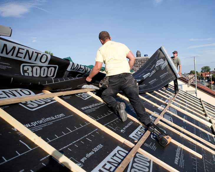
• Roofing underlays – In this case, structural layers that will be located underneath the roof covering and roof/counter battens – i.e. the external sealing that is dealt with in this study – are used to provide weathering protection during the construction phase too. The components involved here include roofing underlay membranes and panels such as wood-fibre underlay panels (see Fig. 4).
As a general principle, joints and penetrations are to be sealed in a rainproof manner and appropriate wind suction protection is to be
provided where necessary. The products and materials used to implement the temporary covering must of course also be suitable for purpose. According to building regulations, this will generally be the case for sub-roofs and for roofing underlays (membranes or panel-form materials) that are suitable and recommended by their manufacturers for this purpose. The manufacturers should provide information on the maximum period of exposure to the elements of their products. Careful attention should be paid to the specified data! Some manufacturers differentiate between the maximum exposure period of membranes with regard to UV exposure and the maximum period of use as a temporary covering. To avoid misunderstandings and confusion, pro clima does not differentiate between these two parameters for its external sealing membranes: with pro clima, the maximum outdoor exposure period also applies to use as a temporary covering.
To ensure the long-term performance of membranes, the maximum outdoor exposure period specified by the manufacturer should not be exceeded.
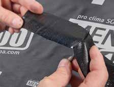
When roofing underlay membranes are used as temporary covering, it is important that the membrane joints (seam protection) and penetrations around nails or screws are sealed in a rainproof manner (see Figs. 5 and 6). Seals around perforations (e.g. with nail-sealing tapes or through the use of membranes with integrated seal protection) is obligatory when underlay membranes are used as temporary covering – regardless of the conditions the membranes will be exposed to in their subsequent covered state (in normal service).
This consideration is not taken into account by many project planners and installers.
It should also be noted that a temporary covering generally cannot provide a level of rain protection that is comparable with that of a finished, covered roof with an additional rain-protection measure implemented underneath. However, this is not the purpose of a temporary covering. The main reason for this is that a temporary covering will be perforated by numerous nail- or screw-type fasteners and that joints can be implemented only in a provisional manner (e.g. around skylights, chimneys etc.). Additionally, the rain loading on a temporary covering is considerably higher than that for the additional rain-protection measure in the subsequent, covered state. By definition, a temporary covering is a non-permanent, provisional measure during the construction phase. As a result, a small level of moisture entry cannot be fully excluded in the case of full exposure to the elements. Small amounts of penetrating
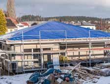
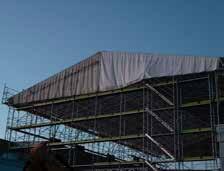
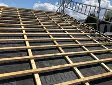
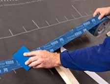
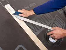
Fig. 6: Sealing of perforations around counter batten fasteners with nail-sealing tapes / compounds or through the verified selfsealing capacity of the membrane itself.
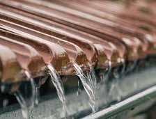
Fig. 7: Protection against the elements is mainly provided by the roof covering on the finished roof. However, water may still breach the roof covering in the case of driving rain, for example.

or complicated roof geometries.
water are not necessarily a defect and can be tolerable in certain cases. However, this can only be assessed by a qualified person on site on a case-by-case basis.
1 2 Protection for structures against water from the outside during normal service (covered state)
When the roof is finished, weathering protection is mainly provided by the roof covering. Nonetheless, low-pitched roofs with a pitch below the so-called ‘standard roof pitch’ (see below for an explanation of this term) can lead to water penetrating under the roof covering in the case of heavy rain events, strong winds, wind-driven snow, melting snow or damage to the roof covering. A second waterproof layer is necessary to deal with these eventualities. There are various additional rain-protection measures available, which differ in terms of the products and materials used and the manner of installation.
The loading on the second waterproof layer underneath the roof covering and, as a consequence, the choice of type of external sealing is dependent on the probability that water will penetrate below the roof covering. The decisive factors here are the roof pitch, the type of roof covering, the standard roof pitch for this roof covering, and the applicability of any so-called increased requirements for the roof in question.
The standard roof pitch is the lowest pitch at which a roof covering can be regarded as rainproof. If the actual roof pitch is below this standard roof pitch, more effective additional rain-protection measures have to be implemented. Data on the standard roof pitches of various roof coverings can be found in national regulations or in technical specifications provided by manufacturers. In the case of manufacturer specifications, note the difference between the standard roof pitch and the minimum roof pitch – the standard roof pitch is the critical parameter here! However, the minimum roof pitch (e.g. if a waterproof sub-roof is being constructed) is often stated or used as a marketing argument.
certain circumstances, these conditions can lead to higher loadings on the second waterproof layer and may require more effective design measures.
1 3 Protection for structures against condensation water from the inside
With regard to protection against condensation water – i.e. protection against the entry of moisture contained in the indoor air during the cold season – timber structures should always have a high degree of potential protection against moisture damage. This is achieved by providing for high drying reserves – which are also necessary to deal with the entry of moisture in an unforeseen manner through leaks in the airtight building envelope. In simplified terms, it can be stated that timber components must be designed in such a way that they allow for drying out on at least one component side (i.e. outside and/or inside).
As a consequence, the structure should be as diffusion-open (vapour-permeable) as possible on the exterior side of the component to allow for drying out to the outside during the cold season (condensation period) when the water vapour diffusion flow is generally from the inside towards the external air.
The diffusion resistance of this component layer is particularly important as the exterior sealing underneath a ventilated roof covering or behind rear-ventilated facade cladding is essentially in immediate contact with the external air and any moisture has to be transferred to the ventilation layer at this location. As a rule, the products used for the external sealing layer (membranes or boards) should be selected to be as diffusion-open as possible (see Fig. 9).
1 4 Protection for the thermal insulation against wind flow
Modern pitched roofs are fully insulated and their supporting layer is not ventilated. In this case, highly diffusion-open underlay membranes should be used that allow as much moisture as possible to escape to the outside.
It should also be noted that manufacturers of covering materials (e.g. roof tiles) sometimes quote their own internal standard roof pitch that can be less than the standard roof pitch as per technical standards. Project planners and tradespeople should take into account that this parameter may deviate from the generally recognised roofing practice. This deviation should be explained in detail to the project client and documented in writing, if necessary in a separate contract.
More demanding conditions may arise as a result of the structural design (e.g. roof surface divided into many different surfaces), the type of use, climatic conditions or the mounting of additional equipment (see Fig. 8). Under
protected against damage due to condensation caused by cooling of the structure (see Fig. 10).
A comprehensive investigation carried out by Holzforschung Austria (the Austrian Forest Products Research Society) demonstrates the extent of the impact of leaks in windtightness layers. Guidelines that were subsequently published based on this investigation define the required level of quality for the implementation of windtight joints at eaves and bargeboards. Other research publications, such that by Bednar and Deseyve (2010) from the Institute of Material Technology, Building Physics and Fire Protection at the Technical
University of Vienna [1], clearly identify the negative effect of wind on thermal insulation.
It can be seen in this report that the effective U-value of a roof structure in the eave area is directly dependent on the wind throughflow. In some cases, the U-value and the resulting heat losses are increased by a factor of up to 6!
To seal the thermal insulation in a windtight manner, windtight layers consisting of appropriate membranes or panel-shaped materials are necessary, combined with windtight sealing (e.g. taping) of joints, overlaps and other transitions.
Fig. 10: In the absence of a windtightness layer (left), wind can flow through the insulation material and cause heat losses. With a windtight sealing layer (right), the stationary air allows the insulation to do its job as properly.
2 . Technologies
As already discussed, roof coverings or facade claddings with gaps (e.g. interlocking coverings with roof tiles or panel cladding on walls) cannot provide absolute protection against water and wind throughflow from the outside. Wind-driven snow and driving rain can force water into the covering/cladding through the gaps and joints and this water can cause damage to structures. For many years now, the outer envelope of building structures has been expected to contribute to thermal protection and these requirements are becoming more stringent. However, the performance of the thermal insulation can be compromised, which in turn leads to higher costs for energy and a reduction in the level of comfort for the end user. In this context, various measures have been implemented in the past to provide additional sealing for vulnerable points
2 1 Previous technologies
Thermal insulation materials, particularly fibrous materials, are effective only when installed in cavities that are filled with stationary air. If this stationary air is swirling or if there is air flow through it, the effectiveness of the insulation is reduced considerably as heat will be removed by convection – this phenomenon is sometimes referred to as ‘wind washing’. In this case, the thermal insulation will not achieve the performance level that is expected and that was assumed in design calculations. This can result in significant energy losses.
As a consequence, a windtightness layer is necessary to prevent wind flow through the insulation layer.
This windtightness layer prevents or reduces both the entry of cold external air and also circulation flow in the insulated cavities. In this way, the performance of the insulation is safeguarded and the structure itself is also
One previous method involved the installation of thin timber shingles behind the joints on roofs. In the case of roof coverings with plain rounded tiles, these shingles were installed behind the joints between the individual roof tiles to direct any penetrating water onto tile directly underneath. In Northern Germany, sections of tar paper (bitumen) were fitted and folded around the tops of the roof tiles for the same purpose. The heating of the roof covering during normal service by solar irradiation caused these sheets of tar paper to join up by melting, which made the covering rainproof. Another method was to coat roof tiles and joints with mortar on the inside. On external walls, facade cladding (panel cladding or smaller plates) was often installed without any additional rainproofing measures. Due to the vertical geometry involved, the risk of penetration of water as a result of driving rain,
for example, is lower on walls than on roofs. In addition, there was generally a masonry wall behind the cladding, which is not as sensitive to water entry as a timber roof truss or fibrous thermal insulation.
At a later stage in technological development, the first, unsophisticated membranes were installed underneath the roof covering with the aim of protecting the component layers and indoor spaces underneath against driving rain and wind-driven snow – initially, these were bitumen membranes (installed over the roof sheathing or freely hanging across the rafters), and subsequently plastic membranes made of PE were used. To improve tear resistance, a scrim reinforcement was stuck onto or integrated into these membranes. Both of these membrane types have a strong vapour-inhibiting effect and are effectively vapour-closed, depending on the definition used.
As a result, unventilated, fully insulated structures were not possible with these membranes due to the risk of condensation formation. For this reason, the compartments between the rafters were not completely filled with insulation and an air gap was left free over the insulation so that rear-ventilation could take place; the result was a so-called ‘cold roof’ (see Fig. 11).
This structural layout has a number of disadvantages, however. For a start, the thermal insulation is not protected against wind circulation, which reduces its effectiveness. In addition, these structures are inefficient as they are not fully insulated. In practice, bitumen membranes with scrim reinforcement age very quickly and become brittle. When work is being carried out on roofs, it is often observed that the scrim reinforcement is the only part of the original membrane that remains or that the membrane
Fig. 11: Older, rear-ventilated ‘cold roof’ structure: Rear-ventilation was necessary between the membrane and the insulation due to the presence of diffusion-inhibiting underlay membranes.
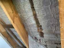
Fig. 12: Old, damaged underlay membrane (with scrim reinforcement) – outgassing of volatile plasticisers has led to significant embrittlement.

Fig. 13: 3-ply structure of a roofing underlay membrane – fleece layers on the outside protect the thin functional layer. This membrane can have a number of different operating principles (e.g. microporous or monolithic).
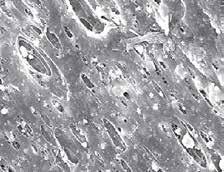
14:
functional layer –Microscope image with 1,000x magnification, the micropores can clearly be seen.
disintegrates without much additional effort (see Fig. 12).
2 2 Currently available technologies
For roof structures, the approaches to joint sealing described above (shingles, sheets of tar paper, coated roof tiles) are no longer permitted as part of current generally recognised practice. Current practice requires full-surface layers consisting of membranes or suitable panels to be installed underneath the roof covering – with the exception of secondary buildings such as carports, barn, sheds. Modern roofing underlay membranes are diffusion-open, i.e. permeable to water vapour, which means that moisture (e.g. from the heated indoor space) can be transferred to the external air during the cold season (condensation period) to keep the thermal insulation and timber structure dry. Various technologies are available for the production of diffusion-open membranes. These technologies will now be introduced and discussed.
2 2 1 Micro-perforated membranes
Micro-perforated membranes are a relatively old technology that was used the 1980s and is no longer common. These membranes, which are generally made of PE plastic, are perforated using spiked rollers during production. When the membrane is observed against background light, these perforations can be seen with the naked eye. The size and shape of these micropores prevents liquid water from penetrating due to the drop shape that the water assumes as a result of its surface tension. As the pores are formed by spikes, they have a funnel-like cross-section. At the narrow end of this funnel, the perforations are relatively tight to water drops. However, they are still large enough to allow water vapour molecules to pass through the membrane. As a consequence, these membranes are sufficiently impermeable to liquid water while simultaneously remaining open to water vapour transport. As a rule, this technology does not achieve very low diffusion resistances. For example, sd values of approx. 3 m, which are actually classified as vapour-inhibiting according to common definitions, are typical for these membranes.
A further disadvantage of this technology is the so-called tent effect that can arise with these membranes. With this phenomenon, water is drawn through the perforations if an absorbent material – e.g. a fibrous insulation material packed between the rafters – is directly in contact with the membrane. This effect is comparable to that which occurs if human bodies, clothing or similar objects are directly in contact with a canvass tent sheet, causing the point of contact to become wet.
2 2 2 Spunbonds
Spunbond materials are fleece fabrics that consist of long fibres. They are manufactured by thermally melting a polymer (e.g. HDPE) and then shaping it with a nozzle into very thin, infinitely long fibres (filaments). These filaments are then extended by an air current or else mechanically. Once they have hardened, they are drawn to produce fleece layers. In the meltblown process, the liquid filaments are torn apart by a hot air current. The resulting fine microfibres, which are then cooled down, create microfibre fleeces. The fibres in meltblown fleeces are significantly finer than those in spunbonds. As a consequence, these fleeces are more dense but have a lower strength. There are also composite materials where a number of different fleeces are combined as laminates – e.g. SMS (spunbond-meltblownspunbond), which has two layers of spunbond around a middle layer of meltblown fibres. The aim here is to combine the positive properties of both materials: the higher mechanical strength of spunbonds and the higher density of microfibrous meltblown materials.
2 2 3 Microporous membranes
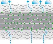
With this type of roofing underlay membrane, membranes made of polypropylene are mainly used as closed films. Polypropylene itself is diffusion-tight. To allow water vapour transport through it, i.e. to create diffusionopenness, calcium carbonate is added to the PP film during the production process to create pores and the film is then stretched. This results in several million tiny micropores per square metre that have a diameter of between 0.02 and 1 µm. Protection against liquid water is based on the principle that water drops formed due to surface tension will not be able to pass through the pores. Water drops typically have a size of around 100 µm or greater. Micropores are smaller by a factor of hundreds or several thousand. In comparison, water vapour molecules have a size of around 0.00004 µm and can pass through the micropores in the membrane by the capillary effect (see Fig. 14).
2 2 4 Monolithic membranes, 3-ply Multiple-ply membranes where the functional film is covered on both sides by fleeces are common. These offer a certain amount of protection against mechanical stress and UV exposure for the film, which itself plays a critical role in important technical properties such as permeability for diffusion, watertightness and protection against driving rain (see Fig. 13).
Monolithic functional films are used on modern roofing underlay membranes. The main
difference relative to conventional microporous technology is that these membranes are pore-free. As a result, these membranes are very impermeable to the passage of liquid water. Water vapour is actively transported along the molecular structure of the functional layer – essentially by diffusion, but also supported by hydrogen bonds. Hydrogen bonds are attractive forces between polar groups on the polymer chains of the functional layer and polar water molecules. These membranes are also referred to as hydrophilic membranes as a result of the water-attracting forces that are at play. All pro clima membranes in this category have monolithic functional layers with a TEEE (thermoplastic elastomer ether ester) membrane. In the case of TEEE, polyether groups are added to polyester to achieve the hydrophilic behaviour described above (see Fig. 15).
In the production process, the functional layer is applied in liquid form between the fleeces (which generally consist of polypropylene) and compressed by rollers. This creates a strong composite.
There are also 3-ply membranes on the market with a TPU (thermoplastic polyurethane) functional layer in the middle. This is generally stuck to the fleeces in the form of a thin film using an additional adhesive (e.g. acrylate). These adhesive bonds have the disadvantage that they are generally not very temperatureresistant (in both the cold and very hot temperature ranges). As a result, delamination of these membranes can occur under the action of temperature. As thin TPU layers are often used for costs reasons, these membranes generally have lower durability than 2-ply TPU membranes, for example (see below).
2 2 5 Monolithic membranes, 2-ply
In comparison with 3-ply structures, 2-ply membranes have their functional layer, which generally consists of thermoplastic polyurethane (TPU), applied onto a backing fleece (e.g. made of polyester) in the form of a coating (see Fig. 16).
The advantage of this is that the sealing layer (TPU) can be directly bonded at joints and that there is no covering fleece over this layer, as is the case with 3-ply structures. In the manufacturing process, TPU is generally applied to the backing fleece in liquid form with a co-extruder.
The liquid coating penetrates into the fleece to a certain extent and surrounds the fleece fibres. In addition, a chemical bond forms between the TPU and polyester. These two phenomena lead to a very strong bond between the two layers, which significantly reduces the risk of delamination of the individual layers at a later stage.
The TPU coating has the additional advantage that it is very elastic (up to 700%) and very robust with regard to mechanical loading
when installation workers are walking across the membrane during construction. TPU also has higher resistance to UV radiation relative to other materials that are used in similar roofing underlay membranes.
The (monolithic) principle of operation is similar to that for the 3-ply structure in terms of moisture transport (see 2.2.4)
2 2 6 Test methods
A number of test methods are available to determine whether a roofing underlay membrane has pores (micro-perforated/microporous) or has a monolithic (closed) functional film. For example, specimens of each product can be clamped between two chambers in a test bottle (see Fig. 17) in a sealed manner. One chamber contains water, the other contains air. The test bottle is oriented so that the water layer is over the membrane specimen. Overpressure is then created in the air chamber underneath the membrane specimen using compressed air (e.g. with a hand-held bellows). With microporous membranes, air bubbles will rise up through the water – a clear indication of small holes or pores in the membrane. In the case of monolithic membranes, no air can penetrate through the membrane. The pulsing motion of the membrane specimen shows that pressure is acting on the membrane. However, no air bubbles rise through the water.
Fleece layers TEEE
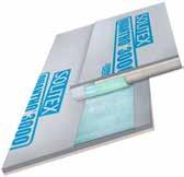
2 3 Weldable roofing underlay membranes
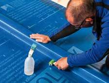
Weldable roofing underlay membranes are required for the implementation of waterproof sub-roofs. They are used on low-pitched roofs with roof covering pitches (often significantly) less than the standard roof pitch. Sub-roofs are subject to more demanding conditions due to driving rain, wind-driven snow etc. and have to provide a greater level of protection than normal roofing underlay membranes. This is achieved by homogeneous welding of membranes to one another, which creates a significantly more rainproof joint than adhesion of normal underlay membranes with additional adhesives. There are two possible methods of installing these membranes around counter battens: additional strips of underlay can be installed over the counter battens (inclusion) or else the underlay is installed underneath the counter battens and additional nail-sealing products are used. The same membrane materials are used for both variants (see Fig. 18).
2 3 1 Diffusion-tight membranes: Bitumen, plastic membranes
In the past, bitumen membranes (‘tar paper’) were installed on roof sheathing consisting of solid wood panels. One disadvantage of
Fig. 16: Different membrane structures. Top: 3-ply underlay membrane with functional layer between two protective fleeces. Bottom: 2-ply underlay membrane; here the functional layer is located above a backing fleece.
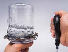
17: Test bottle as a simple method of detecting the presence of micropores – pressure is applied underneath the membrane using a hand-held pump; if micropores are present, air will pass through the membrane and rise up in the form of bubbles.
Different structures. Top: Underlay membrane with functional layer between two protective fleeces. Bottom: Homogeneously weldable underlay membrane; here the functional layers are located on the two exterior sides, around a backing fleece.
bitumen membranes is that their material acts as a vapour barrier. However, the exterior surface of building components and thermal insulation structures should be as diffusionopen as possible to allow any moisture that has entered to escape again. This is not possible or is greatly hindered when bitumen membranes are installed on the outside; rear or other ventilation is often provided in this case. In this layer, located under the strongly vapour-inhibiting bitumen membrane and/or roof sheathing, moisture can be removed to the external air by convection by the air current. However, the additional ventilation layers make the structure thicker and more complicated to build. In addition, ventilation layers cannot always be created in a reliable manner – for example, if air inlet and outlet openings are difficult to create (e.g. close to roof valleys).
In current practice, bitumen, plastic and elastomer membranes are still used that are based on PVC, EVA, FPO (with PE or PP), PIB or EPDM. These materials are still strongly vapour-inhibiting or vapour impermeable, which can lead to the disadvantages described above.
2 3 2 Diffusion-open membranes: Homogeneously weldable TPU membranes
Diffusion-open membranes that can also be homogeneously welded to one another are a modern, relatively new alternative to the conventional underlay membranes described above.
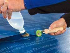
To create these underlays, multiple-ply membranes are used with a backing fleece in the middle (based on polyester, for example) and with a functional layer of thermoplastic polyurethane (TPU) on each side. This arrangement differs from conventional roofing underlay membranes, which generally have their functional layer positioned in the middle between two protective fleece layers (see Fig. 19). The advantage of two-sided, weldable membranes is that the sealing layers can be directly bonded to one another – for example, in the overlap area. In contrast, joints on conventional roofing underlay membranes are bonded using adhesive tapes or self-adhesive strips on the covering and/or protective fleece layers and not on the actual functional layer itself. Another difference is that sub-roof membranes are not stuck to one another using an additional adhesive, but are instead welded to one another in a homogeneous manner. This is achieved by dissolving (liquefying) the TPU layer either thermally using a hot air gun or else chemically with an appropriate solvent (see Fig. 20). The homogeneous welding of the sealing layers creates a ‘uniform’, reliable, seamless seal.
When compared with conventional roofing underlay membranes (bitumen etc.), modern
TPU membranes are vapour permeable, which offers enormous advantages from design and building physics viewpoints and also in terms of protection against condensation water! Additional ventilation layers, which could be unreliable and difficult to implement under certain circumstances, are no longer necessary. As a result, the full depth of the supporting structure can be used efficiently for insulation purposes.
There are additional advantages in terms of installation work. For example, TPU membranes are significantly more flexible, and can thus be folded more easily than bitumen membranes. When counter battens are being enclosed with bitumen membranes, the edges of the counter battens need to be bevelled to avoid sharp fold angles and resulting cracks in the bitumen membrane (see Fig. 21). This is not necessary with TPU membranes. These membranes can also be installed into 90° valleys without the membrane material tearing. Counter battens can also be enclosed with an additional strip of membrane that is fitted later after initial laying of membranes underneath the counter battens (see Fig. 22). This makes overall installation easier. If bitumen or vapour-inhibiting membranes were used, this procedure would not be possible as timber components (counter battens) would be surrounded by a strongly vapour-retarding layer. This runs contrary to currently applicable best practice, which requires a possible method of drying out for timber and wood wood-based materials. This technology is already commonly used and a certain amount of long-term experience with it is available, so it can be regarded as current state-of-the-art practice. Nonetheless, the relatively new technology of homogeneously weldable roofing underlay membranes has generally not yet been included in national construction regulations.
3 . Requirements for external sealing membranes and comparison of various systems
If panels, which are not described here in detail, and membranes are to carry out the functions introduced in Section 1, they must have the required properties and fulfil the relevant requirements. The definition and properties of roofing underlay membranes are dealt with in EN 13859 Part 1 [2] (for roofs) and Part 2 [3] (for walls). These standards also stipulate methods for testing the relevant properties.
In addition, certain national regulations specify further requirements for underlay membranes, such as mechanical strengths or resistance to the passage of water.
3 1 Watertightness – Protection against water penetration from the outside
3 1 1 Static watertightness
The main function of external sealing membranes is to protect building components against moisture from the outside (see Section 1.1).
Various procedures are used to test this property in terms of ‘Resistance to water penetration’ and related classification.
EN 13859 differentiates between the classes W1, W2 and W3. Class W1 is tested in accordance with EN 1928 [4]. The material specimens to be tested (3 samples for each test) are subjected to a water column of 200 mm for two hours. No water penetration may be observed over the entire test period. In a second test, the same procedure is carried out with an artificially aged material specimen. The tests for the classes W2 and W3 are carried out with a different method, which is described in the test standard EN 13111 [5]. In this case, 2.25 L of water is carefully poured over a sloped surface and onto a material specimen. With the cross-sectional area of the test chamber of 300 mm by 150 mm, a 50 mm deep layer of standing water results, which is applied over a period of 3 hours. The requirements for class W2 are still met if water passes through – as long as the quantity of water is less than 100 ml. If membranes do not pass this test, they are to be assigned to class W3.
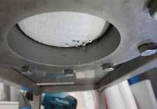
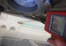
The test for the highest class, W1, can be seen to be significantly more demanding. Alongside testing for the W1 class, a hydrostatic pressure test to determine the maximum water column can also be carried out in accordance with EN ISO 811 [6] (see Fig. 23 a / b). In this test, higher water columns are generally achieved than with the test described above as per
EN 1928 (e.g. as per class W1). However, the water columns measured in accordance with EN 1928 and EN ISO 811 cannot be compared to one another, as the tests use different procedures that simulate different loadings. The W1 test procedure tests watertightness (including after ageing) over a longer loading period (2 hours), e.g. in connection with continuous light rain, whereas the hydrostatic pressure test with increases of 10 cm or 60 cm in the water column per minute simulates relatively short-acting heavy rain with water drops with high impact speeds. In addition, the criteria for stopping the tests are different. The water column test as per EN ISO 811 determines the pressure when three drops have formed at three different points. Very small droplets or drops that repeatedly form at the same location do not count.
In the test in accordance with EN 1928, no water may penetrate at all; this is checked using filter paper that changes colour if it becomes wet. Roofing underlay membranes from pro clima are subjected to testing as per EN ISO 811 to make it easier to compare them with other products. Membranes with monolithic (closed) functional films, such as pro clima SOLITEX MENTO 3000 which can support a water column of 10,000 mm, offer excellent reliability. Membranes with microporous functional layers or those consisting of spunbonds cannot support these high water columns. They often have significantly lower specifications or else no corresponding data is quoted at all in the technical data provided by manufacturers. Membranes that pass water column tests at 2,500 mm and higher values have good watertightness, while those with values around 10,000 mm have exceptional watertightness.
3 1 2 Resistance to driving rain
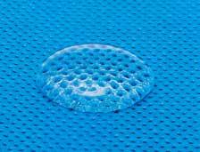
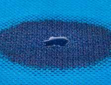
Driving rain is always possible during construction projects. In this case, the loading that acts on a sub-roof or underlay is not simulated in a realistic manner by static watertightness tests. In the case of a driving rain event, rain can impact on membranes with speeds of up to 30 km/h. The water drops can have a diameter of up to approx. 5 mm. During a bad thunderstorm, 30 to 40 litres of rainwater can fall per square metre within a short period of time. The impact of the drops is then combined with the drainage loading of water run-off from the roof, with accumulations of backed-up water. The loading from a weather event of this kind can be very demanding and differs from static
easier.
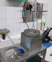
water loading, and for this reason underlay membranes are also subjected to driving rain tests [7]. In these tests, strong wind speeds are created with a blower in a test stand with an area of approx. 2.5 m² (with four fields: two of which have freely hanging membranes, one installed over thermal insulation as a soft substrate, and another over roughly finished, unplaned sheathing boards as a hard substrate). Water is also sprayed onto the blades of the blower, which is then split into drops that are directed by a blower funnel and impact on the test surface (see Fig. 24). The drops that are created simulate natural drops during driving rain events very well in terms of size, distribution and water content. This has been confirmed in comparative experiments. To test the sufficiency of protection against driving rain, multi-stage tests with the procedure described above are carried out, in which the specimens are subjected to between 50 and 60 mm of precipitation with a gradually increasing wind speed of up to 72 km/h (force 8 on the Beaufort wind scale) over a period of 3 hours.
In order to evaluate the test results for the freely hanging membrane, the size, number and distribution of drops at water penetration are recorded and evaluated using a points scale (0 to 10), where a score of 0 represents no or only a few, small drops and thus is the best performance. The requirements in Germany are regarded as fulfilled if a score of <6 is achieved.
Observation of drops is not possible in the test fields where the membrane specimens are installed above a substrate (hard or soft). In this case, the percentage water penetration is determined and compared with defined limit values.
All pro clima underlay membranes have successfully passed this driving rain test. For example, all membranes in the SOLITEX MENTO series demonstrated no water penetration in the freely hanging state, which resulted in the best possible score of 0. High protection against driving rain results from the fact that there are no pores present in the monolithic membrane. High impact speeds or water drops with reduced surface tension are not a problem for these membranes.
In comparison, windtightness membranes with microporous functional layers offer less protection against driving rain and can quickly become permeable under the conditions described above
3 1 3 Effect of dirt on membranes
As described above, the watertightness of porous membranes is based on the surface tension of water drops and the fact that the pores are significantly ‘smaller’ than these drops. However, the surface tension of water can be reduced if other chemical substances
are present. Possible examples on construction sites include cleaning agents, substances contained in timbers (resins or terpenes), wood preservatives (salts and surfactants), solvents and chainsaw oil. The reason for this is that hydrophilic components in these substances become attached to water molecules and come between these molecules. This reduces the attractive forces between the water molecules and the surface tension decreases (see Fig. 25 a / b). In this case, porous membranes will offer significantly lower watertightness – both under static loading and under dynamic conditions in a driving rain test. As a result, considerable amounts of moisture can enter into the thermal insulation and lead to damage to the structure and mould formation. This phenomenon can also be clearly demonstrated in laboratory measurements. For example, samples with both monolithic and microporous membranes were partially coated with chainsaw oil and then subjected to a hydrostatic pressure test in accordance with EN ISO 811; in the test reported on here, half of each sample was treated with oil. Once pressure corresponding to a water column of approx. 3 metres has been applied, significant differences become apparent: no water penetration is observed for the monolithic membrane, even in the area coated with oil, whereas the microporous membrane shows significant water drop formation in the oil-coated area relative to the untreated half of the sample (see Fig. 26). This demonstrates the problem of decreased watertightness on microporous membranes when the surface tension is reduced. Monolithic membranes (such as all pro clima roofing underlay membranes) remain reliably watertight under these conditions.
3 2 Diffusion behaviour – removal of water vapour
to the outside
As explained in Section 1.3 structures with moisture-sensitive materials (e.g. timber, wood-based materials or fibrous insulation materials) in Central European climates should be designed to be as diffusion-open as possible on the outside. External sealing membranes are generally the outermost layer on these structures, so their diffusion resistance is critically important. The property that quantifies the diffusion resistance is the equivalent air-layer thickness for water vapour diffusion (sd value), which is determined in accordance with EN ISO 12572 [8] for underlay membranes with sd values < 0.2 m and in accordance with EN 1931 [9] for sd values ≥ 0.2 m.
Underlay membranes should have sd values that are as low as possible to facilitate the greatest possible removal of moisture to the outside.
3 2 1 Passive moisture transport through microporous membranes
In this case, moisture transport to the outside takes place as a passive process (see Fig. 27). This transport is significant only if there is a relatively high vapour partial pressure gradient. However, this is not always the case on modern, well-insulated structures.
Moisture transport is also dependent on air movement (convection). If there is no convection (e.g. too little of a temperature difference between the inside and outside of the membrane, which is installed over thick thermal insulation), moisture transport will be significantly reduced. This can also happen if the pores on the membranes are blocked by dirt, large amounts of vapour or condensation formation on the inside, for example. Air movement will also be prevented in these cases. Too much moisture may accumulate here and the structure can be damaged.
3 2 2 Active moisture transport through monolithic membranes
Pore-free membranes with monolithic functional layers (e.g. a TEEE film) facilitate active moisture saturation through the membrane material (see Fig. 28). A minimal vapour partial pressure gradient is sufficient for this transport.
If condensate is present at the inner surface in drop form, this condensate is actively transported along the molecular chains of the film in the direction of the vapour partial pressure gradient (generally to the outside). If there is increasing moisture, the vapour transport will even increase because it takes place actively. The diffusion resistance reduces, and the membrane becomes more permeable to water vapour.
3 2 3 Consequences and comparison of systems
As a result of all this, microporous membranes have a significantly higher tendency to experience diffusion-related formation of a water film on their rear side, relative to monolithic membranes (see Fig. 29). Mould formation on the thermal insulation or roof sheathing can occur underneath the membrane due to this water film or to the already increased level of air humidity without condensation (see Fig. 30).
During the winter period, a sealed ice layer can form if the water film freezes. Ice is essentially impermeable to water vapour, and the result is that a vapour-open external layer is turned into a vapour barrier. As a consequence, even more condensation can form and freeze on the ice layer; in an extreme scenario, moisture damage can occur that only becomes noticeable when temperatures have risen again and the
ice layer has melted. With monolithic membranes, water film formation and the resulting risk of an ice layer are practically ruled out due to active moisture transport. This has been observed on real construction projects in comparison with microporous membranes under the same conditions (see Fig. 31).
3 3 Windtightness
As mentioned above, current building regulations do not specify any requirements regarding the installation of windtight building components and the quality level to be achieved. Accordingly, no requirements have been stipulated with respect to the production of materials/products used to install windtightness layers.
In general, it can be stated that pore-free membranes have greater resistance to air and wind throughflow than porous membranes due to their structure (see also Section 2.2.2). Wind can also pass through simple fleece membranes with no functional film to a certain extent. In this regard, roofing membranes with a monolithic functional layer offer the greatest possible protection in terms of windtightness. In addition to the membranes themselves, the joints between membranes and connections to adjacent components also play an important role in achieving windtightness. These joints and connections are generally implemented using adhesive bonds. As a consequence, the quality and above all the durability of these adhesive bonds affects the windtightness. The adhesives used should have high final adhesive strengths and good durability (see Section 4.2).
3 4 Hail protection
A roofing underlay that is used as a temporary covering and/or weather protection during the construction period is not just exposed to normal weather conditions; extreme weather events such as cloudbursts or hailstorms can also occur. Subsequently, when the roof is covered, strong hail events can cause significant damage to the roof covering and lead to greater loading on the underlay installed beneath the covering. As a result, consideration should be given to the level of hail protection offered by membranes.
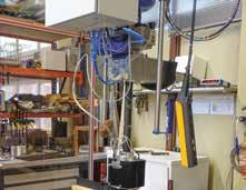
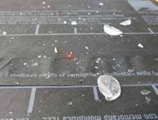
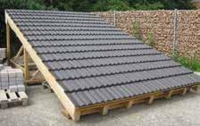
Hail-impact tests have been carried out on pro clima roofing underlay membranes in accordance with the test directives of the Swiss Association of Cantonal Fire Insurance Institutes (VKF/AEAI) [10] to verify the level of protection offered by these membranes. In these tests, the membranes listed in Table 1 on the next page were installed over a wood-fibre insulating panel and were bombarded with hailstones with the largest possible size (diameter 50 mm) from a hail launcher at a speed of 110 km/h (see Figs. 32 and 33). The membranes were subsequently
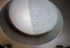
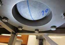
Fig. 26: Hydrostatic pressure test with reduced surface tension – the right-hand side of the membrane sample was coated with chainsaw oil, and subsequently subjected to a pressure test with a water column of approx. 3 metres. Top: Microporous membrane – significant passage of water through the half with oil coating. Bottom: Monolithic membrane – no water penetration.
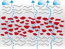
Fig. 27: Schematic representation of the principle of a microporous membrane – water drops cannot pass through the membrane due to their size; water vapour molecules, which are significantly smaller, can pass through the micropores by capillarity.
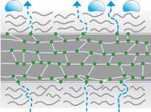
Fig. 28: Schematic representation of the principle of a monolithic membrane – water vapour molecules are actively transported along the molecular structure.
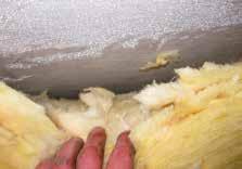
Mould infestation underneath a microporous underlay membrane – the wood fibreboard underneath the membrane has become damp due to weak passive moisture transport, thus providing favourable conditions for mould growth.
visually examined for tears in the area of the hail impact and their watertightness was tested using a hydrostatic water column. The membranes must still be watertight after bombardment with hailstones in order to pass this test.
Many commonly available roof tiles achieve a hail-impact resistance class of HR 4. Roofing underlay membranes from pro clima achieve a higher class of HR 5 when installed over a wood-fibre insulating panel, and thus offer an increased level of protection for roofs. Even if hailstones cause the roof tiles to break, the membranes will keep the roof substructure dry.
3 5 Durability
3 5 1 Durability in general
It is very important that external sealing membranes exhibit the properties described above not just when they are first installed or for the first few years of service life of the building. After all, the membranes will remain in place over the underlying structure for a very long period and are generally difficult to inspect as they are covered by other structural layers. Project planners, installers and clients must be able to have faith in the products that are installed! A service life of around 50 to 60 years is assumed for roof coverings (clay or concrete roof tiles) [11].
After this period, the roof covering is generally replaced. The additional rain-protection measures (e.g. roofing underlay membranes) installed underneath the roof covering must also have a long service life, as they can only be renewed when the roof covering in being replaced.
of the membranes were still in place between the rafters.
One of the conclusions drawn by the authors is that different material properties appear to have a significant influence on the durability of the membranes, alongside the effect of the installation situation (e.g. with regard to UV exposure and thermal loading). Indeed, it was observed that products installed in challenging situations were sometimes more durable than those installed under favourable conditions. As a result, there appeared to be major differences in the material qualities of the membranes that were investigated. The authors also stated that quality and durability tended to correlate with the product price. In simpler terms: cheaper membranes are generally less durable, more expensive products are usually significantly more stable!
3 5 2 Field
tests
the monolithic membrane remains dry.
Unfortunately, the situation encountered on existing buildings is often sobering! Investigations such as the study of the durability of diffusion-open underlay membranes underneath roof coverings carried out by the Aachen Institute for Structural Damage Research and Applied Building Physics [12] have shown that the majority of membranes in service do not even fulfil the minimum requirements. Many of the membranes that were evaluated showed signs of significant disintegration well before the service life of the roof covering was reached. In certain cases, only loose remnants
Hail resistance test. Membranes can be bombarded with hailstones at speeds of up to 110 km/h from a hail launcher. Table 1: Hail impact
The price difference between very cheap membranes with poor performance and more durable membranes that performed better was estimated to be €2 to €4 per m². This would result in average additional costs of €500 to €1,000 for the total roof area of an average single-family home. However, the added value in terms of reliability and durability of structures delivered by this investment is enormous; the initial additional costs are much less than those caused by potential damage to structures in the case of material failure at an early stage of the building’s service life. How can project planners and installers decide which underlay membranes will remain stable and watertight in the long term? The relevant product standards (EN 13859-1/-2) only require verification of W1 watertightness after 14 days of exposure to intense UV light and 90 days of storage at 70 °C. pro clima commissions accredited test laboratories to carry out additional, more demanding tests on all of its membranes and associated products that can be subjected to outdoor exposure. For example, artificial ageing in the case of the SOLITEX MENTO 3000 and SOLITEX MENTO 5000 underlay membranes was carried out not at 70 °C as stipulated in EN 13859, but at 120 °C in order to simulate extreme loading on sealing films from ageing. The test conditions should be considered in comparison with actual service conditions.
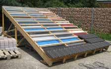
Alongside (internal and external) laboratory tests, long-term tests are also carried out on pro clima underlay membranes – both underneath roof coverings and also with permanent direct exposure to the elements. In this way, the behaviour of these products when subjected to UV radiation and fluctuations in wind, humidity and temperature can be observed under real mechanical loading. To study behaviour with exposure to the elements, the relevant membrane specimens are left without a roof covering and are thus directly exposed to weathering conditions with no protection. To study long-term behaviour under service conditions, a typical construction with counter battens, roof battens and roof tiles as covering was installed over the membranes. In both cases, pro clima underlay membranes and a selection of products from other manufacturers were installed for testing. Samples of the membranes were then taken and investigated at regular intervals. First, a visual check was carried out to detect any noticeable damage; after this, important technical properties such as resistance to the passage of water (hydrostatic column height) were tested in the laboratory.
This continuous evaluation showed up serious differences in the resistance to ageing of various membranes – both under direct exposure and in long-term testing underneath a roof covering.
3 5 2 1 Testing with direct exposure
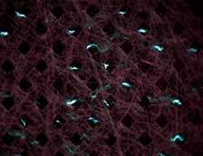
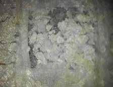
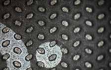
Underlay membranes from pro clima and six membranes from other manufacturers were tested and compared on the outdoor exposure test set-up (see Fig. 34). Measurement of the hydrostatic pressure head on membranes that had not yet been installed or aged showed good watertightness with water columns of the order of several metres. Subsequent measurements after 4 and 8 weeks showed no meaningful changes in this. However, significant changes were detected after 13 weeks of outdoor exposure. In certain cases, the water columns that were measured were less than a fifth of the original values. Under microscopic magnification, signs of serious disintegration were detected for these membranes. Cracks and crumbing were clearly visible here (see Figs. 35a / b).
After 24 weeks, only one of the six membranes from competitors could be subjected to any water column at all. The other five membranes no longer had any watertightness. In contrast, all of the pro clima SOLITEX membranes that were tested were still watertight after this long outdoor exposure period and still had good measurement values (see Fig. 36).
3 5
behaviour in actual service, pro clima underlay membranes (incl. SOLITEX MENTO 3000) and five commonly used underlay membranes from competitors were installed on a test roof under realistic conditions (see Fig. 37 a / b). Prior exposure to the elements was deliberately avoided so that the test would deal only with ageing under covered conditions. The hydrostatic water column and mechanical strength were measured at various points in time. After two years of real-time ageing, samples were taken for the first time after installation and were evaluated. Even at this early stage, an average water column of just 57 cm was measured for one of the membranes. This was a significant disimprovement compared to the new value of over 300 cm. All other membranes showed minimally changed performance. The SOLITEX MENTO 3000 underlay membrane achieved values of > 300 cm. After a test duration of over 11 years, two of the investigated membranes had a water column resistance of just 20 cm, while another had a value of 56 cm. The SOLITEX MENTO 3000 underlay membrane still achieved a very good value of 230 cm after this relatively long ageing period (see Fig. 38 a / b).
3 5 3 UV-resistance
UV rays can damage and even cause complete disintegration of certain materials. In particular, the ageing of plastic membranes that are used as underlays is accelerated by UV radiation.
First, the radiation alters the polymer chains, which then lose elasticity because radiation is able to split organic bonds. In addition, UV causes the loss of volatile plasticisers. Both of these processes lead to embrittlement and possibly also to the formation of cracks in materials. Membranes are subject to significant demands in this regard, particularly during the exposure phase where the membranes are installed, but the roof covering has not yet been fitted; during this phase, UV radiation impinges directly on the membrane surfaces. This phase should be kept as short as possible. In this context, manufacturers specify the maximum permissible period of outdoor exposure in the technical specifications for membranes. These outdoor exposure periods should not be exceeded. If they are exceeded, the membranes will not start to disintegrate immediately; however, the predicted and required overall service lives of the membranes can no longer be guaranteed in the longer term.
Even when they are covered over, the underlay membranes continue to be subjected to loading – for example, at the edge of the roof surface (air inlet openings, etc.) and also in the main surface area of the roof (with interlocking roof coverings such as roof tiles and slates, etc.). Depending on the type of roof
covering used, a UV radiation loading on the underlay of between 2 and 10% of the total radiation acting on the outside of the roof can be assumed. The demands are particularly challenging in unconverted attic spaces where sunlight can enter through windows or skylights and impinge upon the unprotected rear side of the membrane, even in areas with indirect, diffuse UV radiation.
As a consequence, high UV-resistance is critical to ensure that underlay membranes will remain durable in service. This is achieved by a number of means:
• Addition of modern, permanent UV stabilisers in place of volatile plasticisers. This prevents embrittlement due to outgassing of plasticisers.
• Use of thick covering fleeces on multiple-ply membranes. This protects the thin functional layer of the underlay membrane against UV exposure. In simplified terms, it can be stated that UV-resistance increases with increasing thickness and surface weight of the covering fleece.
3 5 4 Resistance to heat
Very high temperatures can occur underneath roof coverings such as roof tiles, slate or metal coverings, and also underneath roof-integrated PV and solar thermal equipment. Measurements such those reported in [12] have recorded temperatures of up to 70 °C under roof tile coverings. Under certain circumstances, even higher temperatures can occur below other coverings. Roofing underlay membranes generally consist of polymers, i.e. long bonded chains of molecules. If they are subjected to heat for long periods, the long polymer chains can break up and degrade. Shorter chains can cause materials to become brittle (similar to the action of UV radiation). If accelerated ageing of this type occurs, plastic membranes can lose their mechanical strength. Highquality, durable products generally have a thermostable functional layer. Monolithic TEEE (thermoplastic elastomer ether ester) functional films have a melting point of over 200 °C, while microporous membranes made of polypropylene have melting points of approx. 160 °C. Alongside their higher melting points, TEEE membranes also have better long-term thermostability than microporous membranes. TEEE has been in use for many years under demanding, even extreme conditions in practical service. For example, TEEE is used in airbags. In this particular application, this material must function reliably at very low and very high temperatures – ranging from
to
tutes. In these tests, durability after artificial ageing in accordance with EN 13859-1 was determined: the tensile elongation behaviour and watertightness were measured after UV and thermal ageing. Temperature ageing at 70 °C for a duration of 90 days is specified in EN 13859-1.
The underlay membranes in the SOLITEX MENTO series were subjected to even more demanding conditions and fulfilled the required performance for this test at both 100 °C and 120 °C. As a result, SOLITEX underlay membranes can boast significantly higher heat-resistance than other typical commercially available membranes and can withstand extreme temperature conditions
3 5 5 Hydrolytic stability
Hydrolysis refers to the splitting of chemical bonds under the action of water. This phenomenon can also occur with certain organic compounds, such as plastics based on carbon chains.
In general, many different substances can lead to an irreversible chemical change in certain materials. Reactions in the presence of acids or bases are usually involved here, but even the supposedly ‘neutral’ substance of water can cause serious degradation of building materials. Hydrolysis involves a chemical reaction between water molecules and plastics that have groups that are attacked by water, such as ester, amide or nitrile groups. Plastics formed by polycondensation are particularly vulnerable in this regard. In simple terms, long-chain polymers are produced by removing water molecules to build up the chains. If water and a certain amount of heat are present where the plastic is in service, the reverse process can occur and these chains break down again. The effect is similar to that with UV radiation. This phenomenon also causes plastics to deteriorate in terms of important properties such as mechanical strength.
4 . Connection products for creating rainproof seals
4 1 General
Underlay membranes need to be sealed in a waterproof manner to create sufficient raintightness. Depending on the type of application, three main types of joints need to be sealed:
• Taping of membrane overlaps and joints
• Joints at the roof edges (e.g. eaves and bargeboards) and at adjacent/penetrating components (e.g. chimneys, skylights etc.)
• Sealing of perforations under the counter battens
4 2 Taped joints
The exterior windtightness layers must be reliably sealed. This applies both to adhesion of membranes to one another and also to the joints between membranes themselves and any penetrations or adjacent building components. As a rule, high final adhesive strength is the most important consideration for adhesion in building applications, such as the creation of windtightness. Adhesives that are formulated to be soft often give the initial impression that they create strong bonds, as thin adhesives penetrate quickly into the substrate, but they have comparatively low final adhesive strengths. These joints can fail under low loads that act over long periods (e.g. those due to wind or relative movement between components). The most suitable adhesives have sufficient initial tack to ensure the adhesive tape sticks to the subsurface initially, but also have high final adhesive strengths to support unforeseen loads.
120 days (this corresponds to around 17 years in reality, according to Satas [14]). The joint can then already be regarded as permanent. As part of tests on the durability of joints, the pro clima adhesion products listed above were also subjected to accelerated ageing under the conditions described above. The test period was also increased from 120 days to 700 days here. Accelerated ageing for 700 days corresponds to 100 years in reality, according to Satas. The test results for these adhesion products from pro clima were also positive for this increased period of accelerated ageing (see Fig. 39).
Watertightness is another important consideration for adhesion products for use in windtightness layers. Rain or condensation on underlay membranes are frequent occurrences in everyday reality on building sites. Even when roof coverings have been fitted, adhesive bonds may still be exposed to liquid water (from condensation run-off or wind-driven rain or snow, for example) under certain circumstances. For this reason, the adhesive technology used should be based on a water-resistant adhesive (e.g. SOLID acrylate adhesive). In contrast, adhesives based on water-soluble acrylate emulsions can liquefy in the presence of water and, in the worst case, can fail (see Fig. 40).
4 2 1 Adhesion with self-adhesive strips

Fig. 39: The ageing resistance of airtightness adhesives can be tested in accordance with the DIN 4108-11 standard. Artificial ageing of 120 days corresponds to around 17 years. Ageing was extended to 700 days (corresponds to 100 years) for pro clima adhesion products.
Watertightness of
over the
The heat-resistance of SOLITEX MENTO membranes has been tested in the laboratory as part of tests by independent testing insti-
In construction practice, problems can arise in connection with hydrolysis if plastics are exposed to liquid water for long periods. This water could arise from condensation either dripping from the roof covering or else forming on the underside of the membrane as a result of high air humidity. On lower quality materials, signs of degradation first appear at localised points (‘pitting’), and later on complete failure of the membrane can occur. To avoid problems of this nature, it is important to select and combine the right materials when manufacturing roofing underlay membranes. For this reason, the covering fleeces and TEEE functional layers of SOLITEX MENTO membranes are designed to provide long-lasting protection against hydrolysis
There are currently no regulated requirements for the strengths and durabilities of windtight adhesive bonds on underlay membranes. However, investigations of the durability of airtightness adhesive tapes and compounds can serve as a guide in this regard. Ideally, adhesion products should be usable both inside (for airtightness) and outside (to create windtightness) too. This holds true for pro clima adhesives such as TESCON VANA tape and the joint adhesives in the ORCON series. A process for accelerated ageing of adhesive joints has been developed at the University of Kassel as part of a research project on quality assurance for adhesive-based joint technology in airtightness layers. This new process is now included in the German DIN 4108-11 standard [13], which demands that adhesive joints have to demonstrate certain specified minimum tensile strengths after being stored at increased air temperature and humidity (65 °C and 80% relative humidity) for a period of
The use of self-adhesive strips has proven itself in service for bonding membrane overlaps in exterior applications (e.g. underlay membranes). The advantage of these strips compared to taping of the overlap with an additional adhesive tape is that the self-adhesive zones are located underneath the overlap and are protected against run-off water. If tape is applied over the overlap, any run-off water will flow directly over or against the taped joint, which increases the loading on the joint and the associated risk of failure. The optimal design for these strips is in the form of adhesive strips on opposing edges of the membranes. When the membranes are installed on site, the adhesive strips can be stuck together, which even works well under unfavourable conditions such as cold or damp (see Fig. 41).
4 2 2 Self-adhesive strips with a sealing lip
Self-adhesive strips with a sealing lip represent a further improvement of this technology. This arrangement can be found on 2-ply underlay membranes with a TPU functional layer. In this
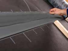
Fig. 41: Membrane overlaps with self-adhesive strips – in this case, the adhesive bond is located under the overlap and is protected against water run-off. The adhesive-to-adhesive bond is reliable even under unfavourable conditions.
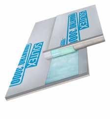
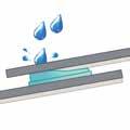

Fig. 42: Self-adhesive strip with a sealing lip – the TPU coating and adhesive extend beyond the end of the backing fleece, which means that the two functional layers can be directly bonded to one another.


Left: Foam-based nail seals only seal above the fleece – water in the upper, water-transporting fleece can enter through the penetration in the membrane. Right: Butyl-based nail seals create a seal at the membrane level and prevent water entry.

Free-flowing
there.
case, the TPU coating extends beyond the edge of the backing fleece layer below it. Some of the width of the adhesive strips is then deliberately positioned over this area with no fleece. In this way, a ‘barrier zone’ is created where the underside of the fleece is protected against capillary entry of water and the functional layers (TPU) of the overlapped membranes can be stuck directly to one another. This prevents seepage of water through the backing fleece, which significantly improves the watertightness of the sealed joint (see Fig. 42)
4 3 Sealing at perforations (nail-sealing)
Nails or screws that are used to fasten counter battens or supporting battens perforate the additional rain-protection measures such as underlay membranes. To prevent or minimise water entry at these points, additional seals between the counter battens and the underlay may be required depending on the applicable requirements (i.e. the class of additional measures); they are obligatory in the case of temporary coverings. Sealing tapes or compounds are commonly used solutions here. As an alternative, membranes that have a verified self-sealing ability may also be used (see 4.3.3).
4 3 1 Nail-sealing compounds
Sealing compounds are foaming, single-component polyurethane substances that expand and then harden in the presence of air and moisture. For this reason, these compounds are applied first and the counter batten is then put in place and fastened. The sealing compound displaces air in the gap between the counter batten and the underlay membrane, and also penetrates deep into the fleece and fibre structures of the counter battens and membranes. In this way, capillary water flow through the covering fleece on the membranes is prevented and, at the same time, the gap between the counter batten and underlay is sealed, meaning that no water can reach the nail or screw fasteners. However, one disadvantage of these systems is that no UV stabilisers are used and that the foam formed often gradually degrades. In addition, the foam only lies over the surface of fleece-free surfaces, such as 2-ply TPU underlay membranes. However, sealing is only effective if there is a chemical bond with the surface, which is not always the case with all materials or products.
4 3 2 Nail-sealing tapes
Conventional sealing tapes (for nails) often only consist of foam. It should also be remembered that these sealing tapes do not seal the actual (nail) perforations in the
membrane layer, but instead seal the gap between the counter batten and membrane through a strong compression effect. If there is insufficient compression pressure at a given location, precipitation water can seep behind the foam tape.
Water transport can also take place through the covering fleece on many composite membranes that have fleece materials over their functional layer, as this covering fleece is not watertight in itself, but serves only to protect the film beneath it.
Nail-sealing tapes made of highly flexible butyl rubber directly seal the perforation in the membrane’s functional layer by penetrating into the hole formed along with the shaft of the nails or screws. This method achieves very good sealing, independently of the compression pressure that acts (see Fig. 43 and 44).
4 3 3 Underlay membranes with perforation protection (‘self-sealing’)
Membranes with intrinsic perforation protection are relatively new, but are already in widespread use. The material properties of these membranes lead to automatic sealing around nail or screw penetrations, and no additional nail-sealing products are necessary as a result. The vast majority of the established products of this type have a 2-ply structure, with an upper functional layer that is often TPU-based. To achieve the required nail-sealing performance, the sealing effect between the counter batten and membrane through surface pressure is harnessed. In addition, the ‘rubber-like’ TPU coating surrounds the penetrating nail and seals it directly. This makes overall installation easier and quicker. As perforation protection is available across the entire surface of the membrane, this system is also less susceptible to (installation) errors. European Technical Assessments (ETAs) have become established as a means of documenting the performance and applicability of products of this type. In contrast with procedures that use additional nail-sealing products, the relevant ETAs verify and document the sealing performance of the membrane itself.
4 4 Use of closed systems from a single manufacturer
In construction practice, the question often arises whether system components for additional rain-protection measures from different manufacturers can be mixed. In particular, less expensive nail-sealing tapes are often used – e.g. simple foam tapes. In general, manufacturers of membranes also supply associated accessories. This ensures that components are suitable and that no incompatibilities occur. Alternatively, accessories from other manufacturers can be used, but in this case these manufacturers should confirm and document suitability and material compatibili-
ty with the relevant underlay membrane. However, it is questionable whether this will actually happen in practice in a manner that is clear to the installer. A further consideration is that mixing various systems often leads to
discussions with parties such as assessors in practice. The use of closed systems from a single manufacturer offers the greatest possible certainty for project planners, installers and developers (see Fig. 45)
5 . Summary and conclusions
Roofing underlay membranes have to fulfil a range of important tasks. During the construction period, they have to protect the underlying structure against the worst that the elements can offer. In subsequent normal service, however, it can also be expected that significant amounts of water (driving rain, wind-driven snow etc.) will enter through the finished roof covering. A fully functional roofing underlay thus provides protection for the thermal insulation and supporting structure against moisture damage over the entire service life of the roof covering, which may be for up to 50 years. On the one hand, liquid water entering from the outside should be kept out; on the other hand, water vapour should be able to escape from the structure to the outside as quickly as possible and in large quantities. For this reason, the membranes should ideally be engineered to be highly diffusion-open. This is feasible with monolithic functional films, in particular, as they have no pores and provide maximum protection against liquid water from the outside with their closed structures, while also ensuring good active moisture transport out of the structure. A high degree of protection against water penetration is reflected in laboratory tests on watertightness (e.g. hydrostatic water column or driving rain tests with no water penetration detected) – this also applies under challenging conditions such as contamination with substances that reduce the surface tension of water. In comparison, the watertightness of conventional microporous membrane decreases greatly in this situation. Active moisture transport through monolithic membranes also significantly reduces the risk of formation of condensation or even ice on the underside of underlay membranes. Microporous membranes tend to encourage water film formation due to their passive moisture transport, which increases the risk of mould infestation and moisture damage to structures.
An additional consideration that is becoming more important in the context of climate change and the associated increase in extreme weather events is the issue of the hail resistance of roofs. Large hailstones are capable of completely destroying roof coverings. In this scenario, it is important that
the underlay layer can offer sufficient protection. Ideal protection is offered by constructions with underlay membranes that have verified hail resistance that is as high as possible (HR 5 class), installed over wood fibreboard panels that form a rigid substrate and can also absorb impact energy thanks to their soft structure. In the past, bitumen and plastic membranes that allowed for no drying out of moisture to the outside were mainly used in the construction of sub-roof underlays. More recently, the use of diffusion-open, homogeneously weldable TPU membranes has become common practice. These offer the same degree of protection, but allow moisture to escape out of the insulation structure by diffusion. In addition, these membranes are generally easier to work with.
A high degree of material durability is required if underlay membranes are to be able to carry out their functions in the long term. In particular, UV radiation and heat can cause plastics to age. For this reason, SOLITEX underlay membranes have stable, plasticiserfree, non-volatile stabilisers. The functional film, which is primarily responsible for the overall performance of a membrane, should be as temperature-resistant as possible. The use of TEEE, which has a high melting point and good long-term thermostability, has proven itself in practice.
The ageing resistance of underlay membranes is tested using a test procedure stipulated by standards, but the artificial ageing that is simulated can only be applied to real service conditions to a limited extent. For example, it has been observed in field tests that many membranes that have been artificially aged in accordance with the relevant test standard (EN 13859-1) and subsequently showed positive test results are subject to premature ageing under realistic conditions – both in the exposed state during the construction period and also later on with a roof covering. The watertightness of some of these membranes was no longer intact after just a few years. In contrast, the SOLITEX underlay membranes that were tested still had very good watertightness at the end of the test duration of over 11 years and thus offer long-term protection to the structures underneath them.
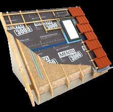


Fig. 45: Underlay membranes and accessories – associated products may be necessary to seal joints, tape over overlaps and seal nail penetrations; ideally, system components provided by the membrane manufacturer should be used.
Further information about installation and design details is available in the planning documentation that is available from pro clima.
You can contact our Technical Support at Technical Support in Germany: Phone: +49 6202 278245
E-mail: support@proclima.com proclima.com
MOLL – bauökologische Produkte GmbH
Rheintalstraße 35-43 · 68723 Schwetzingen · Germany
Tel.: +49 6202 2782 0 · info@proclima.com · proclima .com
1AR04650 2024-10
Your pro clima partner
