Architectural Portfolio


2
Table of Contents Row Home ...................................................................................... 1 1st Year, Fall Term. Boathouse ....................................................................................... 5 1st Year, Spring Term Conceptual Massing ................................................................ 9 2nd Year, Winter Term School ............................................................................................... 13 2nd Year, Spring Term Callowhill Mixed-Use ................................................................ 19 4th Year, Spring Term Academic Building.................................................................... 23 5th Year, Winter/Spring Term Aquaponics - Urban Agriculture ....................................... 29 6th Year, Fall/Winter Term (Ongoing) Technical Examples .................................................................. 35 3
Row Home
1st year, Winter 10 Weeks
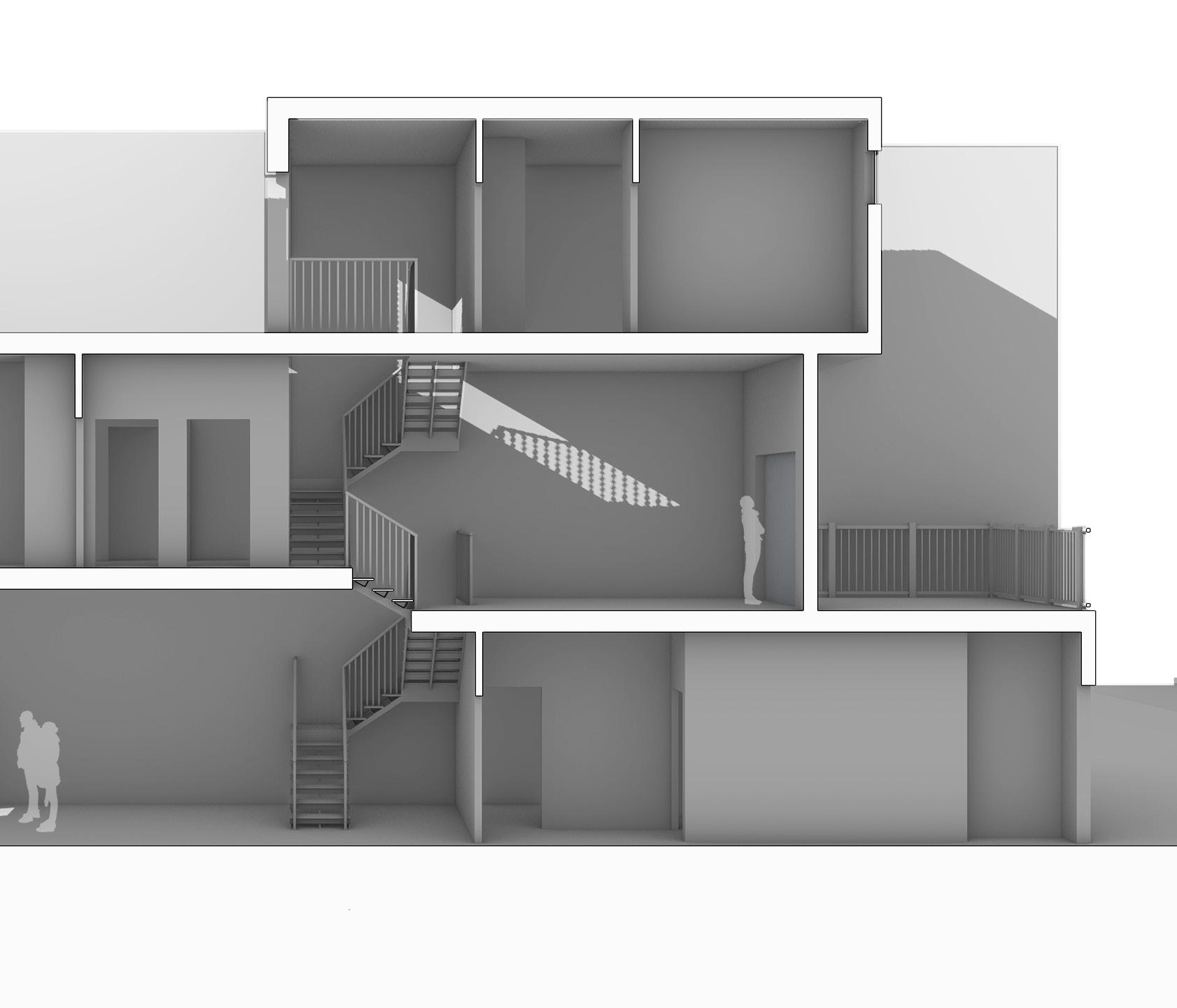
The purpose of this design was to create a row home for a multi generational family. Challenges in the design included how light and air would enter into row homes as they are narrow with adjacent buidlings. This only allows for three exposed sides being the front, back, and top.
The design focused on where private and public programs lie within the design and how that allows light and air enter them. The location of programs was determined by what needed light and air. Gathering from multiple precedents, the location of the staircase is a center of where the most private and enclosed programs would be. As spaces move away, the programs would be open or public.
Having the stairs in the center allow for spaces on either end to have access to light and air.

Along with this, the design includes private spaces be in the upper floors and the public being towards the lowest floor to included guest.
The site is located right inbetween two complete opposite designs of facades. To the right were historical facades, to the left were newer, modern facades. The facade of the design mimiced the historical on the lower levels, the most visible to the public, while the top floor was modern, but less visible.
1
2


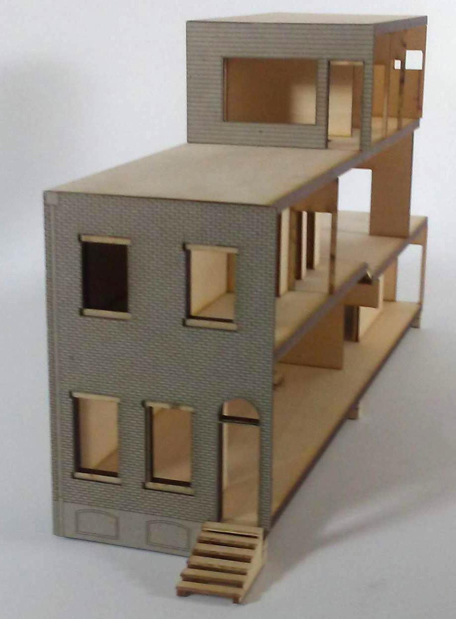 Exterior Facade Detail
Interior Stair Detail
Exterior Facade Detail
Interior Stair Detail


4
The goal of the design is to incorporate how various program spaces work with each other and the users within while the form used influence between exterior to interior actions as forces on the site. The design includes suiting the needs of the client and their organization goals.
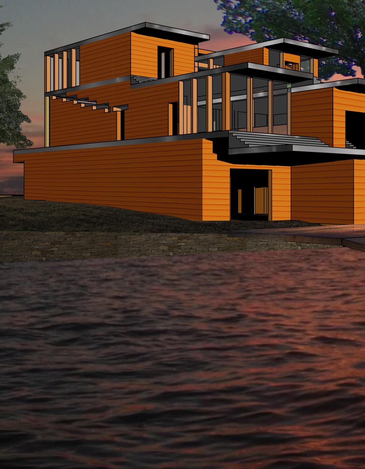
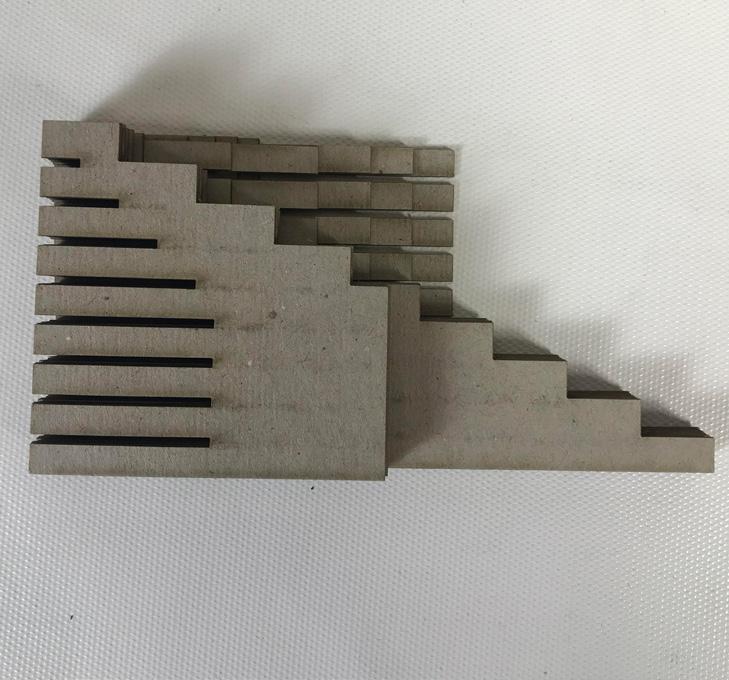
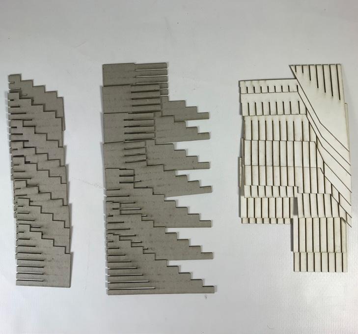
The design used the forces of compression from different elevations of the site onto itself and interlocking of the land to water in order to create the form of the design. This was done by arranging the program spaces to mimic the land, pulling the land upwards and shifting the spaces along the land. The programs themselves include learning and tutoring spaces for the client's needs. These are located at the top as quite, private spaces. Going downwards, include more public spaces such as workout space. Lowest level adjacent to the water is the storage, a large, active space.
The circulation further creates land as if they were different levels in elevation. This includes the large change going upwards from the path on a large set of stairs before multiple small sets of stairs while the design within includes smaller changes.
Boathouse
1st year, Spring 10 Weeks

Digital Circulation Model


 Site Joinery Diagram
7


8
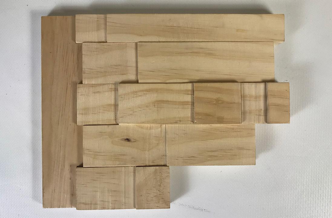
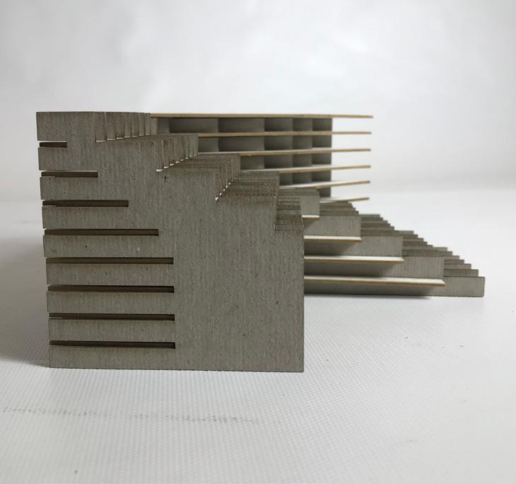
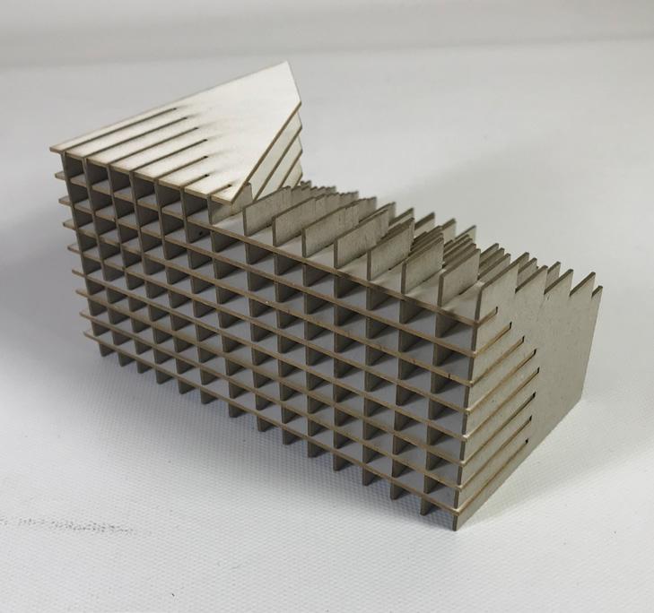
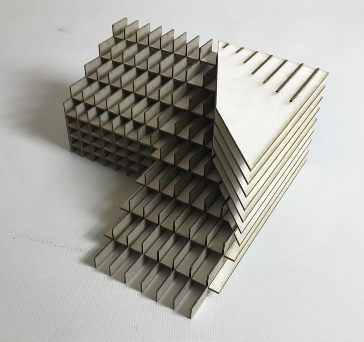
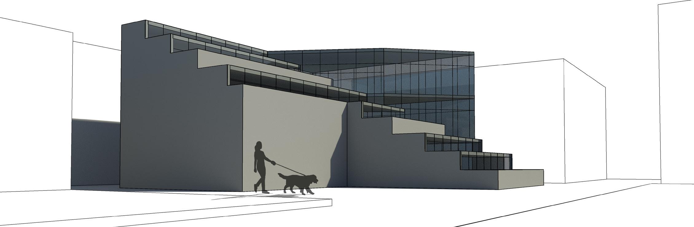
This exercise presented different ways of creating various mass to forms using digital variations and creating a physical model to explore the uses of each. It also introduced use to Revit, how to use it and its various features.

The use of fracture and grade created a combination of a simple cut with a dramatic change. This form showed an interlocking between each other and to represent this, the physical model used the horizontal planes of the fracture to connect with the vertical planes of the grade.
The conceptual site opens the design to a large park area and cuts to allow the sun to continue its path.
Conceptual Massing
2nd year, Winter 6 Weeks
9

10


11
ARCH 225 | B3 Liu OVERALL 3D ISOMETRIC VIEW ISOMETRIC VIEW 12

School
2nd year, Spring 10 Weeks
Designing a school gave me a chance to create connections between a public institue with the communities in which they sit in that would benefit not just the children but for other users of all ages. Typical design issues that arise are which programs should be open/ closed to the community and how the public should have access to them while keeping the safety of the students. Among these design prompts was working with an existing structure and how that would influence my design. Important design decisions that I found is to include seperate courtyard spaces and having a connection between a private classroom to a public library or open space. To achieve this, I pushed and pull different programs to create central, entrance, and gym courtyards. Rather than connecting classrooms to the main library and central courtyard, I created clusters of classrooms with a seperate shared library/study area and ourdoor space. This allows for public programs to be positioned away from the private use of the classrooms without taking away their access to these programs. When designing the overall experssion, I felt it was important to keep the existing structure as I added the new addition, but wanted to connect both through the use of material. The angled roofs allowed for light into otherwise dark areas such as the back street and centeral courtyard while the skylight in the gym faces east as they are used during the evening, mitigating direct light.

14
First Floor Plan Scale: 1/16” = 1’-0” Second Floor Plan 0’ 5’ 10’ 20’ 40’ A B C D E F G H A B C D E F G H A B C D A B C D First Floor Plan Scale: 1/16” = 1’-0” Second Floor Plan Section A-A 0’ 5’ 10’ 20’ 40’ A B C D E F G H A B C D E F G H A B C D A B C D 15

First Floor Plan Scale: 1/16” = 1’-0” Section A-A Section B-B Section C-C Section D-D Section E-E Section F-F Section G-G Section H-H 0’ 5’ 10’ 20’ 40’ South Elevation East Elevation B C D B E F G H A B C D 16


17
Mass to Form

18
Mass to Form Diagram
Callowhill
4th year, Spring 10 Weeks
After 20 weeks of group work in urban planning within Callowhill, a structure was chosen to develop a mixeduse building of residential and program of choice. My preference was a library located closest to the Spring Garden station and at the entrance of the Callowhill site. The library provides a public gathering space that would benefit visitors, commuters, and the residents. The building is one of the first structures to be seen from the I-95 underpass for those taking the Market-Frankford Line.


SPRINGGARDENSTREET

5th 6thstreet 7thstreet


CallowhillStreetHIGHWAY - I76 HIGHWAY-I95 5thstreet 4thstreet 3rdstreet 2ndstreet


21 30' - 0 3 0 '0 " PROPERTY L I NE 2ND FL LIBRARY ABOVE RESIDENTIAL ABOVE 2ND ST. CONNECTION TO SPRING GARDEN STATION MAIN ENTRANCE AERIAL VIEW VIEW ACROSS STREET SITE PLAN


22 VIEW ALONG TRAIL
VIEW AT CALLOWHILL ENTRANCE

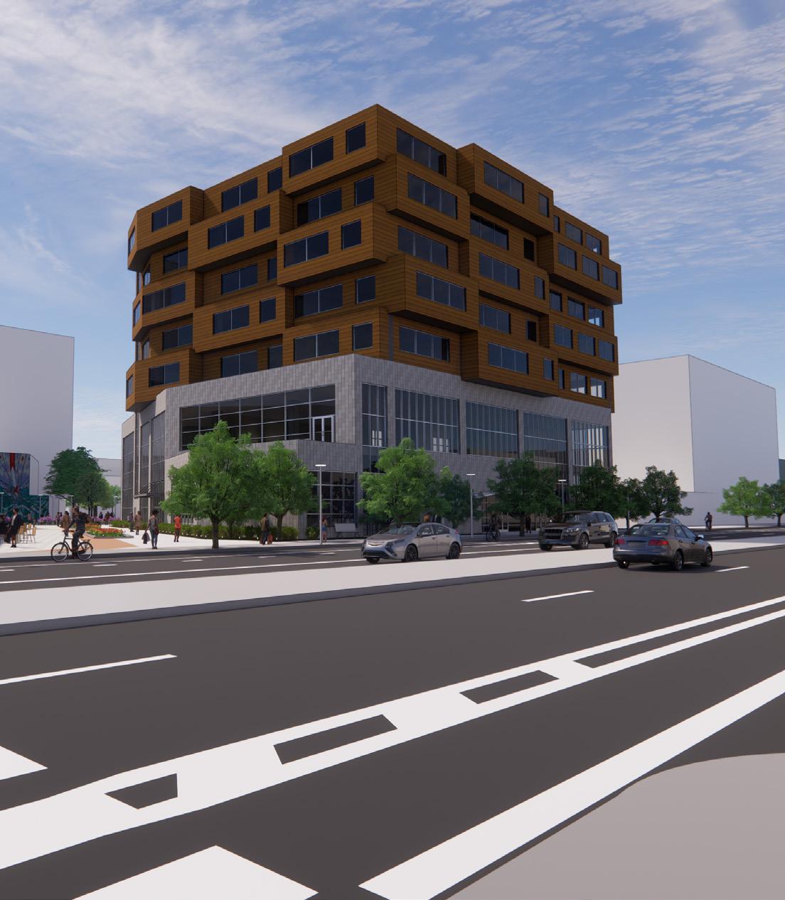
Academic Building
5th year, Spring 10 Weeks
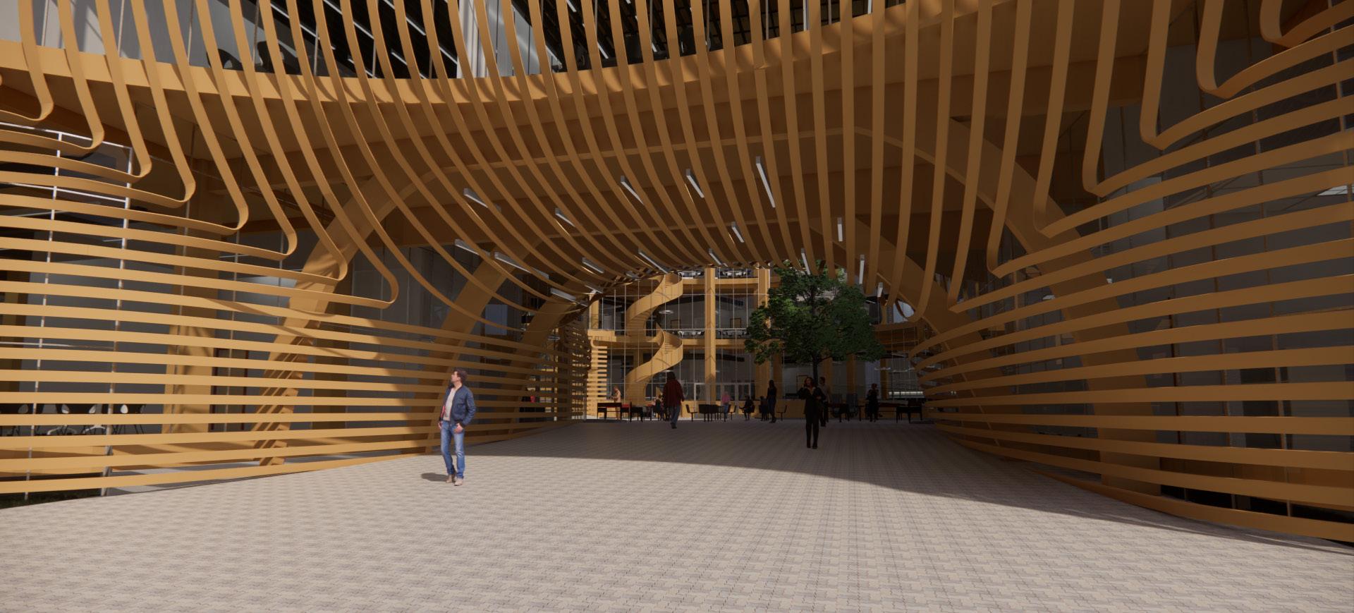
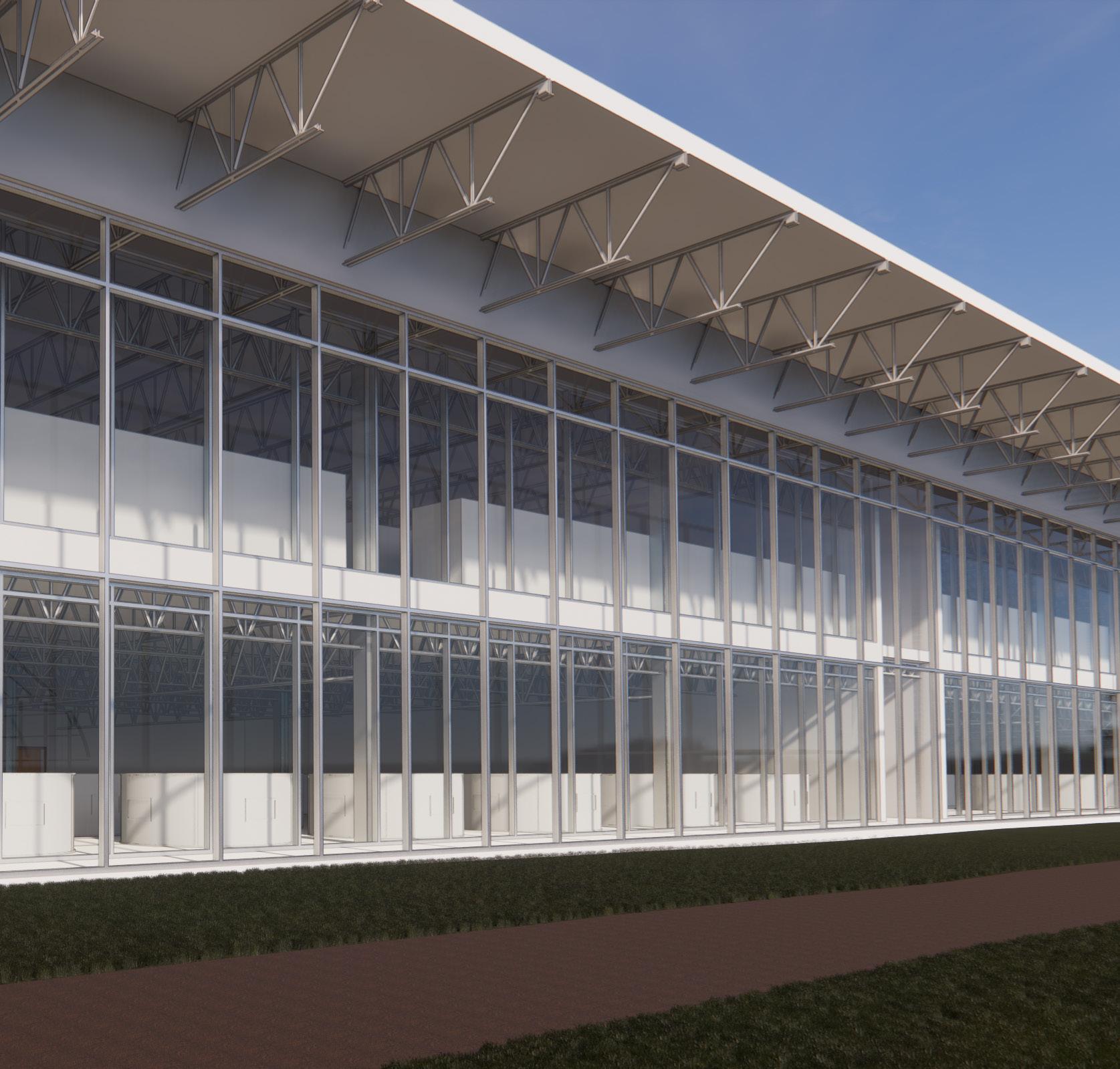
Individual design after an initial 10 weeks of group work in designing an interdisciplinary building on Drexel's campus that merges the school of Biomedical Engineering and Dornsife School of Public Health. This building sits at the corner of Drexel's campus, University City, and Powelton/ Mantua neighborhoods. It serves as a connection between UCity and Drexel while bringing healthcare to the adjacent neighborhoods.
The voids in the building form a path while the curvature of the wood facade draws users through the courtyard.

24


DN UP 25 Fourth Floor Ground Floor South
Elevation North Elevation


Level 4 1/16" = 1'-0" 4 Facade Studies -South Level 2 23' - 0" Level 3 38' - 0" Level 4 53' - 0" Level 1A 4' - 0" 1/16" = 1'-0" Facade Studies -South 26 South Portal Section South Portal Elevation West Elevation
Elevation
East
POROUS PAVEMENT/ PLANTING (Capture rainwater, reduce runo )


MECHANICAL/ COOLING TOWER (Capture rainwater, reduce runo ) FILTER/


GREEN ROOF (Capture rainwater, reduce runo )


RESTROOMS,
STORE RAINWATER USE IN BUILDING (LABS,
ETC.) AND IRRIGATION
2 3
36TH ST 34TH ST
MARKET ST.
27 Sustainability - Water
FILBERT ST. LANCASTERAVE. WARRENST.
Site Plan


28
South Facade
Courtyard
South Portal
West Facade

29 AquaponicsUrban Agriculture 6th year, Fall Term 11 weeks (Ongoing)
Beginning of my senior project throughout the final year of my architecture degree. With the option to design anything, I chose to design an aquaponics facility, the combination between hydroponics and aquaculture, that would be a sustainable food source for urban environments while expanding the knowledge of aquaponics to the community. This approach will help narrow the gap between the world's growing population and decreasing cropland while tackling other issues due to agriculture.
30
FISH CROPS WATER FISH WASTE AQUACULTURE HYDROPONIC WATER WATER WITH AMMONIA WATER WITH NITRATE PLANTS CONSUMES NITRATE CONTAINS EXCESS FISH FOOD AND FISH DROPPINGS AERATE WATER AERATE WATER BACTERIA TURNS AMMONIA INTO NITRATE FILTER SMALL FISH FISH FEED SEEDLING REUSE 31 30 '0 " 30' - 0" 20' - 0" 15 '0 " 25 '0 " 20' - 0" 5 '0 " 140 " 50' - 0" 12 '0 " 15' - 0" 20' - 0" 12 '0 " OFFICE MEETING ROOM GALLERY LOBBY CLASSROOM STORE DESK RECEPTION DESK STACKED HYDROPONIC SYSTEM STORAGE MEETING DESK FISH TANK DISPLAY SHELVES DISPLAY STACKED HYDROPONIC SYSTEM FISH TANK CIRCULATION GLASS CONNECTION CHECKOUT Programs - F.O.H. Aquaponic Cycle
INPUT PROCESS OUTPUT
Programs
TRADITIONAL
32 AQUACULTURE (MODULAR) HYDROPONIC (MODULAR) FILTER (MODULAR) STACKED HYDROPONIC SYSTEM FISH TANKS AIR PUMP AIR PUMP FILTER TANK SUMP TANK CLARIFIER ANNUAL OUTPUT Tilapia: 5 tons 1280 lbs, 6 week cycle ANNUAL OUTPUT Leaf Lettuce: 1,404 cases 24-30 heads/case 40 '0 " 40 '0 " 40 '0 " 30' - 0" 15' - 0" 30' - 0" AREA METRICS Hydroponic Beds: 1200 SF 9810 Plants
Plants / SF
~8
HYDROPONIC
HYDROPONIC WATER BED 550 " 60' - 0"
(MODULAR)
- Aquaponics
- Greenhouse
Programs
33 300’ 600’ 900’ 0’ 128’ 256’ 384’ 0’ 1” = 285’ 1” = 128’ 64’ 128’ 192’ 0’ 1” = 64’ 300’ 600’ 900’ 0’ 1” = 300’ 200’ 400’ 600’ 0’ 1” = 200’ 100’ 200’ 300’ 0’ 1” = 100’ 16’ 32’ 48’ 0’ 1” = 16’ 32’ 64’ 96’ 0’ 1” = 32’ FUTURE EXPANSION First Floor Second Floor Section
CAPTURE RAINWATER & SOLAR PANELS
INCREASE THERMAL MASS
PHOTOVOLTAIC GLASS
MINIMIZE ENVELOPE
CAPTURE RAINWATER
CAPTURE RAINWATER & SOLAR PANELS
Sustainability Methods - Aquaponics
INCREASE THERMAL MASS
PHOTOVOLTAIC GLASS ORIENTATION
Sustainability Methods - Greenhouse
34
ENVELOPE
6th year, Winter Term 11 weeks (Ongoing)

35
AquaponicsUrban Agriculture
Continuation of the Fall Term project, the winter term focuses on technical aspects of structure and systems within my design. The roof's form of the aquaponics building changes to waves to represent water. The pitch of the roof helps guide rainwater towards the front that visitors can view as it flows before being collected within an underground cistern.

36
LOADING/ RECEIVING
FUTURE
FUTURE
OBSERVATION DECK
FUTURE EXPANSION (HYDROPONICS)
FUTURE EXPANSION (HYDROPONICS)
OBSERVATION DECK
Second Floor Plan
AQUACULTURE AQUACULTURE FILTER FILTER PACKAGING -PLANTS PACKAGING -FISH LOADING/ RECEIVING MEETING RM OFFICE LOBBY DRY STORAGE MECH.
EXPANSION (AQUACULTURE)
FILTER FILTER HYDROPONICS HYDROPONICS LOADING/ RECEIVING
1/64" AQUACULTURE AQUACULTURE FILTER FILTER PACKAGING -PLANTS PACKAGING -FISH LOADING/ RECEIVING MEETING RM OFFICE LOBBY DRY STORAGE MECH.
EXPANSION (AQUACULTURE)
FILTER FILTER HYDROPONICS HYDROPONICS
1/64" 37
First Floor Plan
SUMP TANK CLARIFIER FILTER AIR PUMP AIR PUMP HYDROPONICS AQUACULTURE BUILDING CISTERN MECHANICAL MECHANICAL
HYDROPONICS 38
System
Ventilation
AQUACULTURE
Water
Diagram Mechanical
Diagram
39 South Elevation
1/32" = 1' 40 East Elevation South Elevation North Elevation
OBSERVATION
DECK
PROCESSING AREA
FOOTING/ FOUNDATION
ROOF
ROOF FRAMING
SECOND FLOOR
SECOND FLOOR FRAMING
AQUAPONICS FACADE
OUTER FACADE
Exploded Structural Axon
ENTRANCE/ PUBLIC AREA 41
42
Section
Section
Cross
Longitudinal
Technical ExamplesAquaponics Fall Design
8' - 0" 40' - 0" 40' - 0" 40' - 0" A B C D 30' - 0" 30' - 0" 30' - 0" 30' - 0" 12 13 14 15 16 17 43
Section Exploded Axon
44
Roof Framing Axon
Second Floor Framing Axon
Cantilever Framing Axon
Technical ExamplesAquaponics Winter Design
46
Second
Roof Framing Axon
Floor Framing Axon