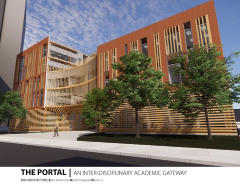
THE PORTAL | AN INTER-DISCIPLINARY ACADEMIC GATEWAY END ARCHITECTURE | Evan Kanterman Nicole Fitzgerald David Liu
TEAM DESIGN DESIGN FOR INTEGRATION . . . . . . . . . . . . . . . . . . . . . . . . . . . . . . . . . . . . . 1 COMMUNITY. . . . . . . . . . . . . . . . . . . . . . . . . . . . . . . . . . . . . 16 ECOLOGY . . . . . . . . . . . . . . . . . . . . . . . . . . . . . . . . . . . . . . . . 26 WATER. . . . . . . . . . . . . . . . . . . . . . . . . . . . . . . . . . . . . . . . . . . 30 ENERGY. . . . . . . . . . . . . . . . . . . . . . . . . . . . . . . . . . . . . . . . . . 32 WELL-BEING. . . . . . . . . . . . . . . . . . . . . . . . . . . . . . . . . . . . . . 35 RESOURCES. . . . . . . . . . . . . . . . . . . . . . . . . . . . . . . . . . . . . . 40
DESIGN DOCUMENTATION . . . . . . . . . . . . . . . . . . . . . . . . 43
INDIVIDUAL DESIGN TEAM DESIGN CRITIQUE . . . . . . . . . . . . . . . . . . . . . . . . . . 66
DESIGN FOR WATER. . . . . . . . . . . . . . . . . . . . . . . . . . . . . . . . . . . . . . . . . . . 69 ECONOMY . . . . . . . . . . . . . . . . . . . . . . . . . . . . . . . . . . . . . . . 70 ENERGY. . . . . . . . . . . . . . . . . . . . . . . . . . . . . . . . . . . . . . . . . . 72 WELL-BEING. . . . . . . . . . . . . . . . . . . . . . . . . . . . . . . . . . . . . . 76 RESOURCES. . . . . . . . . . . . . . . . . . . . . . . . . . . . . . . . . . . . . . 80
DESIGN DOCUMENTATION . . . . . . . . . . . . . . . . . . . . . . . . 86
TEAM DESIGN
ARCH 488, WINTER TERM TEAM MEMBERS: Evan Kanterman Nicole Fitzgerald David Liu
DESIGN FOR INTERGRATION | NARRATIVE AND HYPOTHESIS
END ARCHITECTURE | E N D
HYPOTHESIS If there is an opportunity to bridge the community and Drexel with advanced health opportunities, sustainable living, and inclusivity, then designing a building that creates transparency between the university and the community is vital to the programs. NARRATIVE The interdisciplinary building will serve as a new threshold between Drexel University, the surrounding local communities, and the new academic/ professional development in the area. The site will act as a connector to the entrance of U-City Square, while also reaching out towards the local communities of West Philadelphia. The massing will address the sustainable and programmatic needs of the users through the expressive and unique form. The outer boundaries of the form create an edge surrounding the site and curve inward to shape the path. The three masses are linked by connector spaces that create a central area at the ground level. The mass will be positioned to have a private entrance for the Community Wellness HUB and a main entrance for all users from the courtyard into the building. The courtyard will be filled with porous pavers and a central green gathering space that controls the direction of water flow. Native vegetation will be lined throughout the entire courtyard, that need minimal sun lighting. The circulation will unify clusters of flexible collaborative spaces, private learning spaces, and public wellness spaces to create an inclusive educational experience as users move through the building.
WELLNESS HUB
PUBLIC
PUBLIC THRESHOLD
The building forms a direct threshold that links U-City Square and the research hub to Drexel University.
DREXEL UNIVERSITY
REACHING OUT
The program is specifically designed to reach out to the people in the community and the students of Drexel University.
1
DREXEL ACADEMIC UNITS | DESIGN FOR INTERGRATION
10,260 sqft
7TH FL 6TH FL
25,300 sqft
5TH FL
25,300 sqft 10,260 sqft
4TH FL
25,300 sqft
3RD FL 2ND FL
10,260 sqft
TERRACE 34,700 sqft
1ST FL LAB
LAB OFFICE SUPPORT
SUPPORT
LOBBY
CAFE
AUDITORIUM
BOSSONE RESEARCH CENTER PROGRAM PROPORTIONS AVERAGE ROOM SIZE - AUDITORIUM: 4,200 SQFT - LAB: 600 SQFT - OFFICE: 160 SQFT - LARGE LAB: 940 SQFT
END ARCHITECTURE | E N D
MISSION To promote health and quality of life through education, research, and innovation that integrates engineering and life sciences in a global context VALUES An independent, college-level interdisciplinary academic unit that is positioned to lead cutting-edge university wide initiatives. A rich integration of engineering and the life sciences. Involvement of every student experiential learning through Drexel’s Co-op Program. FACILITIES Bossone Research Enterprise Center Constantine N. Papadakis Integrated Sciences Building FACULTIES Paul Brandt-Rauf, ScD, MD, DrPH : Dean(1) - Previously Dean of Public Health at the University of Illinois at Chicago - At Columbia, he had doubled student enrollment and expanded its research programs with an increase in funding. - Background in research focused on environmental health, written extensively on ethical, legal and social issues in occupational/environmental health policy and practice. Background in teaching various levels of students. CORE - 28 RESEARCH - 5 AFFILIATED 40 EMERITUS - 5 STUDENT BODY Students are encouraged to participate or take leadership roles in BIOMED-related groups: Alpha Eta Mu Beta (AEMB) Drexel Biomedical Graduate Association (DBGA) Drexel Biomedical Undergraduate Association (DBUA) Medical Device Entrepreneurship Association (MDEA)
SCHOOL OF BIOMEDICAL ENGINEERING, SCIENCE AND HEALTH SYSTEMS Information about Biomedical engineering at Drexel University and the program spaces within Bossone Research Enterprise Center.
2
DESIGN FOR INTERGRATION | DREXEL ACADEMIC UNITS
END ARCHITECTURE | E N D
OPEN OFFICE OFFICE
LAB
7TH FL
10,260 sqft
6TH FL
25,300 sqft
5TH FL
25,300 sqft
4TH FL
10,260 sqft
3RD FL
30,900 sqft
2ND FL
10,260 sqft
1ST FL SUPPORT
34,700 sqft LOBBY CLASSROOM AUDITORIUM
STUDY
NESBITT HALL PROGRAM PROPORTIONS AVERAGE ROOM SIZE (1) - AUDITORIUM: 4,300 SQFT & 1750 SQFT - CLASSROOM: 900 SQFT - OFFICE: 160 SQFT - LAB: 940 SQFT - STUDENT LOUNGE: 725 SQFT
MISSION (2) To improve the health of communities and populations through innovative education, research, and cooperation with other civic, business, and academic institutions committed to solving our world’s most difficult health challenges. VALUES (2) Health as a human right and the importance of social justice to health. Translation of knowledge into actions to improve population health and eliminate health disparities. Sustainable and equitable community partnerships. FACILITIES Dornsife School of Public Health, Nesbitt Hall Dornsife Center for Neighborhood Partnerships West Philadelphia Community Center (WPCC) (Partnership) FACULTIES (WITHIN RESEARCH INTERST) Ana V. Diez Roux, MD, PhD, MPH: Dean(3) - Known for her research on the social determinants of population health and the study of how neighborhoods affect health. - Research areas include social epidemiology and health disparities, environmental health effects, urban health, psychosocial factors, cardiovascular disease epidemiology, and more. - Awarded for her contributions to public health from the American Public Health Association. CHONIC HEALTH PROBLEMS - 52 BEHAVIORAL HEALTH - 48 HEALTH EQUITY/SOCIAL JUSTICE - 53 HEALTH IN COMMUNITIES - 106 NOVEL RESEARCH METHODS - 90 PUBLIC HEALTH POLICY - 38 PUBLIC HEALTH THEORY - 6 STUDENT BODY Become part of a close-knit and diverse community within Drexel. Student experience extends beyond classrooms and labs to include organizations, school-wide events, and many other ways to get involved. Drexel’s hometown of Philadelphia offers many opportunities to put public health into practice.
DORNSIFE SCHOOL OF PUBLIC HEALTH Information about Dornsife School of Public Health at Drexel University and the program spaces within Nesbitt Hall.
3
PROGRAM RELATIONSHIP | DESIGN FOR INTERGRATION
END ARCHITECTURE | E N D
LAB LAB OFFICE OFFICE
OFFICE OFFICE
LAB CLASSCLASSROOM ROOM
OFFICE
LAB CLASSCLASSOFFICE ROOM ROOM
SUPPORT SUPPORT
OFFICE
OFFICE
HUB HUB MORE ACTIVE
CLASS-CAFECAFE CLASSROOM SUPPORT ROOM LOBBY LOBBY ADJACENCIES ADJACENCIESAUDITAUDITPROXIMITIES PROXIMITIES ORIUM ORIUM STUDY STUDY
SUPPORT
CLASSROOM
HUB INTERMEDIATE POINT MORE ACTIVE USED AT ALL HOURS STUDY INTERMEDIATE POINT
The intermediate point between classroom and AUDITauditorium is open study space or individual study space to offer different types of learning once class ORIUM gets out.
CLASSROOM
DIRECT DIRECT CONNECTION CONNECTION AUDITAUDITLOBBY LOBBY ORIUM ORIUM MORE PEOPLE MORE PEOPLE
CAFE
CAFE
ADJACENCIES PROXIMITIES
AUDITAUDITCLASSORIUM ORIUM ROOM
The classroom and lab are located near office spaces since this is a highly frequented area of relationships.
STUDY STUDY
ADJACENCIES PROXIMITIES
INTERMEDIATE INTERMEDIATE POINT POINT USED USED AT ALL AT HOURS ALL HOURS STUDY STUDYLAB
HUB HUB MORE MORE ACTIVE ACTIVE
LAB
AUDITORIUM
LOBBY
AUDITORIUM
ADJACENCIES & PROXIMITIES
AUDITORIUM
LOBBY
The diagram infers which spaces should be near each other for a more efficient building design.
4
CLASSCLASSROOM ROOM
LAB LAB
DIRECT CONNECTION LOBBY MORE PEOPLE
AUDITORIUM
DIRECT CONNECTION
The auditorium and lobby share a direct connection to hold more people.
DIRECT CONNECTION MORE PEOPLE
DESIGN FOR INTERGRATION | PROGRAM RELATIONSHIP
END ARCHITECTURE | E N D
LOBBY CAFE
LOBBY (1000 SF
LOUNGE (725 SF)
CAFE (225 SF)
KITCHEN (160 SF)
RESTROOM (100 SF)
UTILITY (100 SF)
STORAGE (100 SF)
LARGE LAB (940 SF)
LAB (600 SF)
SUPPORT OFFICE (160 SF)
LAB
OPEN OFFICE (350 SF) CONFERENCE ROOM (275 SF)
OFFICE
WAITING AREA (100 SF) CLASSROOM (900 SF)
CLASSROOM STUDY
STUDY (160 SF) COLLABORATIVE AREA (225 SF)
AUDITORIUM
MULTIPURPOSE (2100 SF) AUDITORIUM (4200 SF)
PROGRAM DAYLIGHTING
The amount of daylighting differs by the type of space.
PROGRAM SIZE
The average program sizes differ based on the amount of use and the type of space.
The programming is broken down by spaces that a typical school of public health and biomedical engineering building would have. The amount of sunlight, the size, and relationships are all important for the framework of how the program is laid out. The relationships help form a effective building that minimizes travel distances and allow students, faculty, and the community to use the supporting spaces around where they need to go.
5
MASSING ITERATIONS 1 | DESIGN FOR INTERGRATION
INITIAL MASSING ITERATION
Basic uniform mass showing full original volume.
6
END ARCHITECTURE | E N D
INITIAL MASSING ITERATION
Split the mass into multiple parts form separation of program at the ground level.
Adjust the heights of each mass to respond to the site and fit the required program.
INITIAL MASSING ITERATION
Connect the masses with bridges to tie the programs together above.
DESIGN FOR INTERGRATION | MASSING ITERATIONS 1
END ARCHITECTURE | E N D
SITE AXON (SE)
SITE AXON (NW)
VIEW FROM FILBERT STREET
VIEW FROM U-CITY
UPPER LEVEL PROGRAM
VIEW FROM 36TH STREET
VIEW FROM WARREN STREET
POWELTON/ MANTUA
U-CITY
DREXEL
GROUND LEVEL PROGRAM
7
MASSING ITERATIONS 2 | DESIGN FOR INTERGRATION
END ARCHITECTURE | E N D
MASSING MASSINGSTUDIES STUDIES| |SITE SITEC C
ITERATION 1
The massing is a simple U-shape that is cut back on the corner at 36th Street for the first 6 floors and the top 5 floors are a L-shape.
COURTYARD COURTYARD
ARCH 488 | END |C END ARCHITECTURE ARCHITECTU MASSING STUDIESARCH | 488 SITE
ITERATION 2
The massing is an U-shape that cuts back 10’ on the interior and exterior upper floors and has a tower extruding upwards.
ITERATION 3
AVOIDING AVOIDING SHADOWS SHADOWS
| SITE CSTUDIES | SITE C SSING
The massing is a U-shape that cuts a path through the site on the first two floors and doesn’t on the upper floors.
COURTYARD
CONNECTION CONNECTION
Using Using a simple a simple U-shape U-shape forms forms a courtyard a courtyard could could allows allows for communities for communities to come to comePushing Pushing the mass the mass minimizes minimizes the amount the amount of shadow Using of shadow a simple castcast onU-shape the on other-side the other-side forms aofcourtyard the of theCarving could Carving away allows away from forfrom communities the mass the mass creates to creates come a path a path from Pushing from U-City the U-City into mass into Drexel’s minimiz Drexel ca together together and and congregate. congregate. U-shape and and minimizes minimizes amount of shadow of shadow fromfrom the adjacent the|adjacent building.and congregate. makes makes Filbert Filbert Street Street feel feel less less like U-shape alike back a back and street. minimizes street. ARCH 488 | ENDU-shape ARCHITECTURE ARCH 488the|| END EtheNamount DARCHITECTURE E Nbuilding. Dtogether
COURTYARD
ARCH 488 | END ARCHITECTURE | E N D
AVOIDING SHADOWS
CONNECTION
HEAT HEAT STORMWATER STORMWATER HEATcampus and VEGETATION VEGETATION ple U-shape forms a courtyard could allows for communities to comeSHADOWS Pushing the mass minimizes the amount ofCONNECTION shadow cast on the other-side of theCONNECTION Carving away from the mass creates a path from U-City into Drexel’s AVOIDING SHADOWS AVOIDING together and congregate. and minimizes the amount of shadow from theUtilizing adjacent building. makes feel less like a back street. CoolCool roofsroofs offeroffer a unique a unique advantage advantage ofU-shape minimizing of minimizing the buildings the buildings impact impact on the on the Utilizing the open the open courtyard courtyard as a as collection a collection ofCool stormwater ofFilbert stormwater roofsStreet offer would awould unique help help reduce advantage reduce the of theminimizing The The open the open courtyard buildings courtyard also impact also creates on creates the the opportunity theUtilizing opportunity the foropen afor open acourtyar open space sp
mass munities minimizes to come the amount Pushingofthe shadow mass minimizes cast on thethe other-side amount of the shadow Carving cast on away the from other-side the mass of the creates Carving a pathaway fromfrom U-City theinto mass Drexel’s creates campus a path and from U-City into Drexel’s campus and urban heatheat island island effect. runoff and and astreet. cistern a cistern system system could could allow 100% forstreet. 100% recyclable recyclable water water onurban site. on site. heatvegetation island vegetation effect. to cool to cool down down this this areaarea in the in hotter the hotter months runoff months and more amore cistern thanthan a sys sto nd minimizes the amount U-shape of shadow and minimizes from the adjacent the amount building. ofurban shadow from theeffect. adjacentmakes building. Filbert Street feel lessrunoff likeMASS amakes back Filbert Street feel less like allow a for back TO FORM
The massing diagrams show the intent of the courtyard.
METHODOLOGIES: METHODOLOGIES: TheThe site site massing massing waswas developed developed based based off of offresponse of response to the to the surrounding surrounding site site andand CONCLUSION METHODOLOGIES: CONCLUSION & CITATIONS & CITATIONS The site : Inmassing conclusion : In conclusion was the developed the massing massing based has has a off good aofgood response response response to to the the to surrounding the site site andand to shadows to site shadows andof th neighborhoods. neighborhoods. TheThe massing massing waswas alsoalso a response a response to sustainable to sustainable strategies strategies thatthat could could be implemented be implemented intointo the the However, neighborhoods. However, moving moving forward Theforward massing it is it key was is key that also that the a response the massing massing looks to sustainable looks at sunlight/glazing at sunlight/glazing strategies that in more in could more detail bedetail implemented andand possibly possibly imp into design. design. TheThe series series of diagrams of diagrams above above werewere developed developed in Illustrator in Illustrator withwith a Revit a Revit background background to show to show the the process process of the of the the design. the stepping stepping Theback series back offofthe off diagrams the street street on above the on the Nothern were Nothern developed sideside of the in of Illustrator the building building to with reduce toareduce Revit thebackground “heaviness” the “heaviness” of to the show of the massing the mass pr massing massing iteration. iteration. Warren massing Warren Street. iteration. Street.
The U-shape was used to create a courtyard, pushing the form allowed light in, and creating a void emphasized a path. The use of an open courtyard would collect rain water, along with having cool roofs, and vegetation were among the factors that formed the mass.
8
DESIGN FOR INTERGRATION | MASSING ITERATIONS 3
END ARCHITECTURE | E N D
ITERATION 1
Opens towards UCity and neighborhood while connecting to Drexel from above
ITERATION 2
Faces UCity while using 36th street, due to frequent traffic, to create seperate entries for the private neighborhood and South of Market St.
Neighborhood Neighborhood
Health Health Development Development
Base form of site
Connection to adjacent areas
E E
Neighborhood Neighborhood
Health Health Development Development
UCityUCity to Drexel to Drexel PathPath
W W
Extend path and connect to Drexel
Increase Increase sunlight sunlight
Angle towards sun
MASS TO FORM
MASSING ITERATIONS Different important forces of the site influenced the massing in various ways. These include a connection to adjacent spaces such as the public/ neighborhood, a connection between UCity and Drexel, and solar access.
9
FINAL MASSING ITERATION | DESIGN FOR INTERGRATION
1. MAXIMUM SITE COVERAGE & FAR
2. CARVE OUT PATHS & SPLIT MASSING
NW AERIAL
10
END ARCHITECTURE | E N D
3. PUSH/PULL VOLUMES
4. UNIFY THE MASSING
SE AERIAL
DESIGN FOR INTERGRATION | MASSING DIAGRAMS
END ARCHITECTURE | E N D
RIGID EDGES
TRANSPARENT CORE
FLEXIBLE CONNECTIONS
UNIFIED PROGRAM
ENTRY POINTS
VERTICAL CIRCULATION
GROUND FLOOR CIRCULATION
UPPER FLOOR CIRCULATION
11
PRRECEDENT RESEARCH | DESIGN FOR INTEGRATION
END ARCHITECTURE | E N D
Level 6
COURTYARD
Level 4
Level 5 Sun Shading Reduces Heat Gain and Glare
Sun Shading Reduces Heat Gain and Glare
COURTYARD
Level 3
Passive Cooling Strategies
Level 4
Level 3
Passive Cooling Strategies CLASSROOMS
Level 2 CLASSROOM
LAB SUPPORT
LAB
Level 2
LAB SUPPORT
LOCKERS/GOWNING
LAB SUPPORT
Key Programmatic Relationships
OPEN STUDY
OPEN LAB
Level 1
Support Collab. Study Private Study Classroom Lobby Lab/Lecture
CLASSROOM
CLASSROOM
Key Programmatic Relationships
LAB SUPPORT
LAB
OFFICES
OPEN STUDY
PRIVATE STUDY
LOCKERS/GOWNING
Level 1
Support Study Office Classroom Lobby Lab/Lecture
MONASH UNIVERSITY S&T RESEARCH & INNOVATION BUILDING
UNIVERSITY OF ARIZONA HEALTH SCIENCES EDUCATION BUILDING
Location: Monash, Australia Architect: DesignInc Year Completed: 2010 Area: 183,000 sf Year: 2010
Location: Phoenix, Arizona Architect: CO Architects Year Completed: 2012 Area: 268,000 ft² Year: 2012
12
DESIGN FOR INTEGRATION | PROGRAM INTENT
END ARCHITECTURE | E N D
GROUND LEVEL
Auditorium/Lecture Hall Building Service Classroom Clinical Room Flex Alcove Lab Lobby Multi-Purpose Space Office/Study Pod Open Study/Lounge Help Desk Simulation Room Vertical Circulation
LEVEL 2-4
Programs Auditorium/Lecture Hall Building Service Classroom Clinical Room Flex Alcove Lab Lobby Multi-Purpose Space Office/Study Pod Open Study/Lounge Help Desk Simulation Room Vertical Circulation
LEVEL 4-6
Typical Dimensions 35’ x 45‘ Varies 20’ x 30’ 30’ x 60’ 20’ x 20’ 30’ x 60’ Varies 40’ x 60’ 10’ x 12’ Varies 10’ x 10’ 10’ x 12’ Varies
LEVEL 6-8
Floor Basement Level 1 Level 2 Level 3 Level 4 Level 5 Level 6 Level 7 Level 8
Area 6,520 sf 22,878 sf 22,878 sf 26,538 sf 26,538 sf 13,420 sf 13,420 sf 6,520 sf 6,520 sf
Total
165,258 GSF
13
PROGRAM INTENT | DESIGN FOR INTEGRATION
END ARCHITECTURE | E N D
PROGRAM INTENTION | SITE C
GROUND LEVEL
ARCH 488 | END ARCHITECTURE | E N D
LEVEL 2-4
LEVEL 4-6
LEVEL 6-8
METHODOLOGIES: As part of the narrative we started collaging ideas for spaces that would be in the building. On the CONCLUSION & CITATIONS : Since the building is curved it’s important to have more open areas with furniture that blog one of the comments was “Start to consider how these spaces may evolve in our project” and “it could be good can be moved and is flexible. There’s some opportunity for spaces that we didn’t include in here that we want too add to have another version of this board that directly connects to the diagrams we create in order to fully describe the moving forward. intended experience”. I started mapping where these spaces would be.
PROGRAM INTENT IMAGE BOARD
Types of spaces used throughout the building.
14
DESIGN FOR INTERGRATION | PROGRAM INTENT
END ARCHITECTURE | E N D
PROGRAM INTENTION | SITE C
GROUND LEVEL
ARCH 488 | END ARCHITECTURE | E N D
LEVEL 2-4
LEVEL 4-6
LEVEL 6-8
METHODOLOGIES: As part of the narrative we started collaging ideas for spaces that would be in the building. On the CONCLUSION & CITATIONS : Since the building is curved it’s important to have more open areas with furniture that blog one of the comments was “Start to consider how these spaces may evolve in our project” and “it could be good can be moved and is flexible. There’s some opportunity for spaces that we didn’t include in here that we want too add to have another version of this board that directly connects to the diagrams we create in order to fully describe the moving forward. intended experience”. I started mapping where these spaces would be.
PROGRAM INTENT IMAGE BOARD
Types of spaces used throughout the building.
15
SITE A ANALYSIS | DESIGN FOR COMMUNITY
END ARCHITECTURE | E N D
RACE ST.
SEPTA TROLLEY WALK FROM TROLLEY SEPTA MFL WALK FROM MFL WALK BIKE
33ND ST.
CHERRY ST.
C LA
CUTHBE
ND
ST
ER
AV E. 32ND ST .
B
RT ST.
CA
33ND ST .
34TH ST .
A
JFK BLVD .
36TH ST .
ARCH ST .
MARKET
ST.
1 LANCASTER AVE. LOOKING AT SITE
2 LANCASTER AVE LOOKING AT DREXEL
3 LANCASTER AVE. LOOKING AT SITE
4 ACROSS MARKET LOOKING AT SITE
QUALITATIVE: School building cluster, corner lot
QUANTITATIVE: 1 main path, access
EXPERIENTIAL OVERVIEW LOT TYPE: Corner lot, entire site surrounded by streets on the East, South, & West edges ACTIVITY: Mild activity on Lancaster Walk, mostly students. Market and JFK are busy NOISE: Moderate due to cars and trucks on Market SUNLIGHT: Shadows on the site vary by time of day and season WIND: Most wind blow from the North SITE VISIBILITY: Visible from the East and South, sorta blocked on the West but can see when closer on Lancaster Walk, completely blocked on North side VEHICULAR TRAFFIC: High for this area anywhere from large trucks to bikes TRANSPORTATION: 2 min. from trolley, 5 min. from subway, 2 min. from bus, direct bike access
16
QUANTITATIVE: ½ in shade, 2 min from pub. Trans., Surrounded by streets on N,S,W
QUANTITATIVE: ½ in shade, 3 traffic lights
DESIGN FOR COMMUNITY | SITE B ANALYSIS
END ARCHITECTURE | E N D
LA
NC
WA R
C
RE
1
AS
TE
RA VE .
NS
T.
FILBERT
ST.
2
B 3
MARKET ST. 4
A
1 FILBERT ST. WEST APPROACH
2 FILBERT ST. EAST APPROACH
QUALITATIVE: Little to no vehicle or foot traffic, one building across street (Annex), shading from adjacent building
EXPERIENTIAL OVERVIEW LOT TYPE: Covered from the west and east by adjacent buildings ACTIVITY: Busy with pedestrian and vehicular traffic on Market St. while quiet on Filbert St. NOISE: Noisy due to traffic on Market St., but gets quieter towards Filbert St. SUNLIGHT: Lots of sun throughout the day WIND: Strong winds on Filbert St. but calms down on Market St. SITE VISIBILITY: Higher visibility along South due to wider street, but lower visibility from the North VEHICULAR TRAFFIC: High traffic along Market St. while there is almost to no traffic on Filbert St. TRANSPORTATION: Trolley and Train access from corners of the block
3 MARKET ST. WEST APPROACH
4 MARKET ST. EAST APPROACH
QUALITATIVE: Lots of traffic, large open street, no shading on north side
SITE B Site B is located at 3501 Market Street and is close to multiple transit stops and is convenient for public transportation. On top of that, it is adjacent to a wide and busy street so it can be viewed from further away. The site sits between opposite neighborhoods where the north is quieter and closer to the neighborhood while the south is business and academic.
17
SITE C ANALYSIS | DESIGN FOR COMMUNITY
END ARCHITECTURE | E N D
3
C 2
4
1 1 VIEW FROM FILBERT STREET
B
QUALITATIVE: Corner Lot, Accessible by Transportation, Light Traffic, Quiet, Mostly Student Activity
2 NORTH VIEW FROM 36TH STREET
QUANTITATIVE: ½ in shade, 2 min from pub. Trans., Surrounded by streets on N,S,W
EXPERIENTIAL OVERVIEW LOT TYPE: Corner lot, surrounded by streets on the North, South, and West edges.
A
ACTIVITY: Relatively low activity, mostly students and local residents. 36th street is busiest. NOISE: Mostly quiet, but likely to increase due to new development around the site. SUNLIGHT: Shadows on the site vary throughout the day. WIND: Most wind blows strongly from the West and slightly from the North. SITE VISIBILITY: Visible from the North/East, can be seen from 31st St./Powelton Ave. VEHICULAR TRAFFIC: Relatively low activity, mostly students and local residents. TRANSPORTATION: 2 min. from trolley, 6 min. from subway, 2 min. from bus, direct bike access.
3 SOUTH VIEW FROM 36TH STREET
QUANTITATIVE: ½ in shade, 2 min from pub. Trans., Surrounded by streets on N,S,W
4 VIEW FROM WARREN STREET
QUANTITATIVE: ½ in shade, 2 min from pub. Trans., Surrounded by streets on N,S,W
SITE C The site is affected mostly by the adjacent Drexel academic buildings, as well as the taller buildings to the North/West of the site. These buildings influence the sun/wind exposure, as well as the views around the site. The area is generally quiet, but with the addition of over half a dozen new buildings close by in U-City Square over the next few years, including new Drexel academic facilities, the site activity will increase dramatically.
18
DESIGN FOR COMMUNITY | SITE B ANALYSIS
END ARCHITECTURE | E N D
3.
6.
2.
12.
10.
10.
14.
4.
3.
8. 12.
4.
8.
SITE A 1. 2. 3. 4. 5. 6. 7. 8. 9. 10. 11. 12. 13. 14.
8.
SITE B Buckley Field Armory/Squash Center Cannaris Hall (Student Housing) Nesbitt Hall U-Cross (Student Housing) Cira Centre One Drexel Plaza Pearlstein Business Learning Center 30th Street Station Lebow College of Business The Korman Center Bulletin Building Drexel College of Engineering Disque Hall
6.
1.
11.
1. 2. 3. 4. 5. 6. 7. 8. 9. 10. 11. 12.
5.
1.
5.
1.
11.
SITE C Domus (Student Housing) Arrive University City (Student Housing) 3535 Market Street (Mixed Use) Innovation Plaza (U-City Square) Powel School URBN Center URBN Annex Drexel Science Center Summit (Student Housing) Urban Eatery Buckley Tennis Courts Drexel Recreation Center
1. 2. 3. 4. 5. 6. 7. 8. 9. 10. 11. 12.
Shops/Restaurants Summit (Student Housing) Community Education Center Drexel Science Center URBN Annex Quaker Court (Student Housing) URBN Center The Link (Student Housing) 3535 Market Street (Mixed Use) Arrive University City (Student Housing) Powel School 3735 Market (Mixed Use)
SITE COMPARISON
Site A is located directly adjacent to student housing and is surrounded by academic buildings, all with large footprints and tall in height. Site B on the other hand, is surrounded directly by more modest buildings, mostly academic but with some variation. Site C is surrounded by the most dense development, with the tall buildings of U-City square nearby.
19
SITE C ANALYSIS | DESIGN FOR COMMUNITY Powelton Village
END ARCHITECTURE | E N D
Mantua
WALK SCORE
88 TRANSIT SCORE
98 BIKE SCORE
95
Drexel C olleg & Health e Of Nursing Professio ns
Drexel University
10
5
MFL TRANSPORTATION MAP
The transportation map highlights the methods of transportation near the site.
The chosen site is walkable for Powelton Village, Mantua, and Drexel Communities. It's a block away from Market Street which has bike lanes, the trolley line, the Market Frankford Line, and Buses stops; which is convenient for people traveling into the city. The new interdisciplinary building is situated across the street from the College of Nursing building.
20
AR AR A SELF-DIRECTED SELF-DIRECTED PROGRAM PROGRAM ||DESIGN COMMUNITY COMMUNITY COMMUNITY WELLNESS WELLNESS HUB HUB HUB FOR COMMUNITY |WELLNESS EQUITABLE COMMUNITIES SELF-DIRECTED PROGRAM | COMMUNITY WELL
1.1.1.Future Future FutureSearch Search SearchNetwork Network Network 1. Future Search 2.2.2.Dean Dean Deanofof ofthe the theSchool School Schoolofof ofPublic Public PublicHealth Health Health 2. Dean of the S 3.3.3.Dean Dean Deanofof ofthe the theSchool School Schoolofof ofBiomed Biomed BiomedEng., Eng., Eng.,Science, Science, Science,&&&Health Health HealthSystems Systems Systems 3. Dean of the S 4.4.4.Dornsife Dornsife DornsifeCommunity Community CommunityAdvisory Advisory AdvisoryCouncil Council Council(DCAC) (DCAC) (DCAC) 4. Dornsife Com 5.5.5.Community Community Communityofof ofMantua Mantua Mantua 5. Community o 6.6.6.Community Community Communityofof ofPowelton Powelton Powelton Village Village Village 6. Community o 7. Volunteer Sta 7.7.7. Volunteer Volunteer VolunteerSta Sta Sta 8. Faculty & Stud 8.8.8.Faculty Faculty Faculty&&&Students Students Students 9. Civic 101 Clas 9.9.9.Civic Civic Civic101 101 101Class Class Class
y of Powelton Village 7. Volunteer Sta Sta ARCHITECTURE 8.END Faculty & Students | E N D tudents9. Civic 101 Class lass
Systems
NG
1. Future Search Network 1. Future Search Network 2. Dean of the School of Public Health 2. Dean of the School Public Health 3. of Dean of the School of Biomed Eng., Science, & Health Systems 3. Dean of the School BiomedCommunity Eng., Science, & Health Systems 4. of Dornsife Advisory Council (DCAC) 4. Dornsife Community Advisory Council (DCAC) 5. Community of Mantua 5. Community of Mantua 6. Community of Powelton Village 6. Community of Powelton Village 7. Volunteer Sta 7. Volunteer Sta 8. Faculty & Students 8. Faculty & Students9. Civic 101 Class 9. Civic 101 Class
ARCH 488 | END&ARCHITECTURE RESEARCH SCIENCE HUB MAP | E N D The site is located within the research and science hub.
RESEARCH RESEARCH RESEARCH&&&SCIENCE SCIENCE SCIENCEHUB HUB HUBMAP MAP MAP (1) (1) (1)Master Master MasterPlan Plan Plan
SELF-DIRECTED PROGRAM | COMMUNITY WELLNESS HUB
1. Future Search Network 2. Dean of the School of Public Health 3. Dean of the School of Biomed Eng., Science, & Health Systems 4. Dornsife Community Advisory Council (DCAC) 5. Community of Mantua 6. Community of Powelton Village 7. Volunteer Sta 8. Faculty & Students 9. Civic 101 Class
RESEARCH & SCIENCE HUB MAP NEIGHBORHOOD ENGAGEMENT MAP
The site is located in the (1)neighborhood Master Plan engagement area.
NEIGHBORHOOD NEIGHBORHOOD NEIGHBORHOODENGAGEMENT ENGAGEMENT ENGAGEMENTMAP MAP MAP (1) (1) (1)Master Master MasterPlan Plan Plan RESEARCH & SCIENCE HUB MAP (1) Master Plan
1.1.1.Fu F 2.2.2.DD 3.3.3.DD 4.4.4.DD 5.5.5.CC 6.6.6.CC ARCH 7.7.7.VV 8.8.8.Fa F 9.9.9.CC
1. Futur 2. Dean 3. Dean 4. Dorn 5. Com 6. Com 7. Volun 8. Facul 9. Civic
NEIGHBORHOOD ENGAGEMENT MAP COMMUNITY WELLNESS HUB MEANING COMMUNI The missing of the is to Plan heal, unite, and bridge the community. (1) HUB Master
COMMUNITY COMMUNITY COMMUNITYWELLNESS WELLNESS WELLNESSHUB HUB HUBMEANING MEANING MEANING NEIGHBORHOOD ENGAGEMENT MAP (1) Master Plan
COMMUNITY WELLNESS HUB MEANING
1. Future Search Network 2. Dean of the School of Public Health 3. Dean of the School of Biomed Eng., Science, & Health Systems 4. Dornsife Community Advisory Council (DCAC) 5. Community of Mantua 6. Community of Powelton Village 7. Volunteer Sta 8. Faculty & Students 9. Civic 101 Class LINKAGE
STAKEHOLDERS OF THE HUB
The main stakeholders of the interdisciplinary building and the HUB.
STAKEHOLDERS OF THE HUB
LINKAGE LINKAGE LINKAGE 1.1.1.Future Future FutureSearch Search SearchNetwork Network Network
1. Future Search Network 2. Dean of the School of Public Health 3. Dean of the School of Biomed Eng., Science, & Health Systems 4. Dornsife Community Advisory Council (DCAC) 5. Community of Mantua 6. Community of Powelton Village link1. the three user groups. The Future SearchSta Network 7. Volunteer 2. Dean of the School of Public Health 8. Faculty & Students 3. Dean of 101 the Class School of Biomed Eng., Science, & Health Systems 9. Civic
LINKAGE
The program aims to LINKAGE
MISSION OF THE EXPANSION
MISSION OF THE EXPANSION
program will engage and educate the community. MISSION OF THE EXPANSION
1. Future Search Network 4. Dornsife Community Advisory Council (DCAC) 2. Dean of the School of5. Community Public Health of Mantua Community of Powelton Village 3. Dean of the School of6.7. Volunteer Biomed Eng., Science, & Health Systems Sta Faculty & Students 4. Dornsife Community8.Advisory Council (DCAC) 9. Civic 101 Class 5. Community of Mantua 6. Community of Powelton Village MISSION MISSION MISSIONOF OF OFTHE THE THEEXPANSION EXPANSION EXPANSION 1. Future SearchSta Network 7. Volunteer 2. Dean of the School of Public Health 8. Faculty & Students
21
LOBBY LOBBY
SERVICE
SERVICE
SERVICE
SERVICE
MISC. LABSMISC. LABSMISC. LABS MISC. LABS
LOBBY
ARCH 488 | END ARCHITECTURE | E N D
HEALTH HEALTH HEALTH HEALTH MANAGEMENT MANAGEMENT & MANAGEMENT & MANAGEMENT & & POLICY POLICY POLICY POLICY DEPARTMENT DEPARTMENT DEPARTMENT DEPARTMENT
LOBBY
AUDITORIUM AUDITORIUM AUDITORIUM AUDITORIUM MULTIMULTI- MULTIMULTIPURPOSEPURPOSE PURPOSE PURPOSE SERVICESERVICE SERVICE SERVICE ROOM ROOM ROOM ROOM SERVICESERVICE SERVICE SERVICE
BASEMENT
COMMUNITY COMMUNITYCOMMUNITY & ENVIROMENTAL ENVIROMENTAL & & ENVIROMENTAL & ENVIROMENTAL ENVIROMENTAL & ENVIROMENTAL & & ENVIROMENTALENVIROMENTAL & HEALTH & HEALTH & HEALTH & OCCUPATIONAL OCCUPATIONAL OCCUPATIONAL OCCUPATIONAL OCCUPATIONAL OCCUPATIONAL OCCUPATIONAL OCCUPATIONAL PREVENTION PREVENTION PREVENTION HEALTH HEALTH HEALTH HEALTH HEALTH HEALTH HEALTH HEALTH DEPARTMENT DEPARTMENT DEPARTMENT DEPARTMENT DEPARTMENT DEPARTMENT DEPARTMENT DEPARTMENT DEPARTMENT DEPARTMENT DEPARTMENT
LEVEL 4
CARDIOVASCULAR ENGINEERING & NEUROENGINERING
CARDIOVASCULAR ENGINEERING & NEUROENGINERING
CARDIOVASCULAR ENGINEERING & NEUROENGINERING
STUDY STUDY STUDY STUDY STUDY STUDY STUDY STUDY SPACES SPACES SPACES BIOMEDICALSPACES BIOMEDICAL SPACES BIOMEDICAL SPACES SPACES SPACES BIOMEDICAL MEDICAL BIOMEDICAL BIOMEDICAL BIOMEDICAL NEERING ENGINEERING ENGINEERING ENGINEERING ENGINEERING ENGINEERING ENGINEERING ENGINEERING UBLIC & PUBLIC & PUBLIC & PUBLIC & PUBLIC & PUBLIC & PUBLIC & PUBLIC EALTH HEALTH HEALTH HEALTH HEALTH HEALTH HEALTH HEALTH BIOMATERIALS BIOMATERIALS BIOMATERIALS BIOMATERIALS ARED SHARED SHARED SHARED SHARED SHARED SHARED SHARED AND TISSUE AND TISSUEAND TISSUE AND TISSUE BIOMECHANICS ENGINEERING ENGINEERING ENGINEERING ENGINEERING STUDY STUDY SPACES SPACES
STUDY SPACES
MOST PUBLIC MOST PUBLIC MOST PUBLIC
LEVEL 5
MOST PUBLIC
PUBIC AND PRIVATE (COMMUNITY & STUDENTS) PUBIC AND PUBIC PRIVATE AND PUBIC PRIVATE (COMMUNITY AND PRIVATE (COMMUNITY & STUDENTS) (COMMUNITY & STUDENTS) & STUDENTS) SEMI PRIVATE (STUDENTS) SEMI PRIVATE SEMI PRIVATE (STUDENTS) SEMI PRIVATE (STUDENTS) (STUDENTS) MOST PRIVATE (STAFF) MOST PRIVATE MOST PRIVATE (STAFF) MOST PRIVATE (STAFF) (STAFF)
The program organization is based on departments in each school.
22
COMMUNITY HEALTH & PREVENTION DEPARTMENT
SEMI PUBLIC SEMI (COMMUNITY PUBLIC SEMI(COMMUNITY PUBLIC CAN(COMMUNITY USE) SEMI CANPUBLIC USE)CAN (COMMUNITY USE) CAN USE)
LEVEL 6
PROGRAM ORGANIZATION
LEVELS 2-3
BIOINFORMATICS AND COMPUTATIONAL
EPIDEMIOLOGY & BIOSTATISTICS DEPARTMENT
STUDY SPACES
LEVEL 1
BIOINFORMATICS AND COMPUTATIONAL
EPIDEMIOLOGY & EPIDEMIOLOGY EPIDEMIOLOGY & & BIOSTATISTICS BIOSTATISTICS BIOSTATISTICS DEPARTMENT DEPARTMENT DEPARTMENT
LEVEL 1A
BIOINFORMATICS AND COMPUTATIONAL
HEALTH MANAGEMENT & POLICY DEPARTMENT
EPIDEMIOLOGY EPIDEMIOLOGY & EPIDEMIOLOGY & & EPIDEMIOLOG BIOSTATISTICS BIOSTATISTICS BIOSTATISTICS BIOSTATIST DEPARTMENT DEPARTMENT DEPARTMENT DEPARTME
STUDY STUDY STUDY STUDY STUDY SPACES SPACES SPACES SPACES SPACES BIOMEDICAL BIOMEDICAL BIOMEDICAL BIOMEDICAL BIOMEDICAL BIOME ENGINEERING ENGINEERING ENGINEERING ENGINEERING ENGINEERING ENGIN & PUBLIC& PUBLIC & PUBLIC & PUBLIC & PUBLIC& PU HEALTH HEALTH HEALTH HEALTH HEALTH HEA BIOMATERIALS BIOMATERIALS BIOMATERIALS BIOMATERIALS SHARED SHARED SHARED SHARED SHARED SHA AND TISSUE AND TISSUE AND TISSUE AND TISSUE BIOMECHANICS BIOMECHANICS BIOMECHANICS BIOMECHANICS ENGINEERING ENGINEERING ENGINEERING ENGINEERING STUDY STUDY STUDY STUDY SPACES SPACES SPACES SPACES STUDY STUDY SPACES SPACES
MISC. LABS MISC. LABSMISC. LABSMISC. LABS
BIOINFORMATICS AND COMPUTATIONAL
ENT
END ARCHITECTURE | E N D
SELF-DIRECTED STUDY | PROGRAM ORGANIZATION
CARDIOVASCULAR ENGINEERING & NEUROENGINERING
NT &
PROGRAM ANALYSIS | DESIGN FOR COMMUNITY
LEVELS 7-8
DESIGN FOR COMMUNITY | PROGRAM ANALYSIS
END ARCHITECTURE | E N D
SELF-DIRECTED STUDY | PROGRAM ORGANIZATION
ARCH 488 | END ARCHITECTURE | E N D
CLASSROOMS & LABS & STUDY SPACES CLASSROOMS & LABS & STUDY SPACES CLASSROOMS & LABS & STUDY SPACES
CLASSROOMS & LABS & STUDY SPACES
CLASSROOMS & LABS & STUDY SPACES
CLASSROOMS & LABS & STUDY SPACES
AUDITORIUM
MULTIPURPOSE ROOM
SERVICE
SERVICE
BIOMECHANICS BIOMEDICAL ENGINEERING CARDIOVASCULAR & NEURO
BIOMEDICAL ENGINEERING & PUBLIC HEALTH SHARED
BIOINFORMATICS & GENETIC DISEASES
BIOMATERIALS & TISSUE ENGINEERING/ DRUG DELIVERY CARDIOVASCULAR & NEUROENGINEERING BIOINFORMATICS & COMPUTATIONAL
CLASSROOMS & RESEARCH LABS CLASSROOMS & RESEARCH LABS
HEALTH MANAGEMENT & POLICY DEPARTMENT
CLASSROOMS & RESEARCH LABS CLASSROOMS
STUDY SPACES
CLASSROOMS & LABS & STUDY SPACES
SIMULATION & CLASSROOM
STUDY SPACES
CLASSROOMS & LABS & STUDY SPACES
SIMULATION & CLASSROOM
STUDY SPACES
CLASSROOMS & LABS & STUDY SPACES
STUDY SPACES
CLASSROOMS & LABS & STUDY SPACES
SIMULATION & CLASSROOM LOBBY
MULTIPURPOSE ROOM
SERVICE
HEALTH CARE ADMINISTRATION/ MANAGEMENT & HEALTH POLICY HISTORY OF PUBLIC HEALTH & PUBLIC HEALTH ETHICS
EPIDEMIOLOGY & BIOSTATISTICS DEPARTMENT
ENVIROMENTAL & OCCUPATIONAL HEALTH DEPARTMENT
COMMUNITY RESEARCH, CLINICAL TRIALS, STATISTICAL MODELING
BIOMEDICAL ENGINEERING
COMMUNITY HEALTH & PREVENTION DEPARTMENT
VIOLENCE & TRAUMA, REPRODUCTIVE & SEXUAL HEALTH, CHILD HEALTH
BIOMECHANICS
PHYSICAL ACTIVITY, SLEEP, MENTAL HEALTH, SUSBTANCE ABUSE
BIOMATERIALS AND TISSUE ENGINEERING & DRUG DELIVERY
NEURO DISORDERS, NUTRITION, CARDIOVASCULAR, CANCER
CARDIOVASCULAR ENGINEERING & NEUROENGINEERING
EMERGENCY PREP.,HEALTH DISEASE
SERVICE
BIOINFORMATICS AND COMPUTATIONAL BIOENGINEERING
MOST PUBLIC SEMI PUBLIC (COMMUNITY CAN USE) PUBIC AND PRIVATE (COMMUNITY & STUDENTS)
*CLASSROOMS/LABS SHALL BE USED BY BOTH BIOMEDICAL ENGINEERING & PUBLIC HEALTH CLASSES REGARDLESS OF DEPARTMENT*
*AREAS OF STUDIES INTENTIONALLY OVERLAP ON FLOORS*
SEMI PRIVATE (STUDENTS) MOST PRIVATE (STAFF)
PUBLIC & PRIVATE PROGRAM
The diagram shows the public and private programs by floor. (1) & (2) & (3)
PUBLIC & PRIVATE PROGRAM The diagram shows the public and private programs by floor.
DEPARTMENT BREAKDOWN
The diagram shows the departments by floor. (1)
DEPARTMENT BREAKDOWN The diagram shows the departments by floor.
AREA OF STUDY BREAKDOWN
The diagram shows the focus of studies by floor. (2) & (3)
AREA OF STUDY BREAKDOWN The diagram shows the focus of studies by floor.
23
STAKEHOLDER INTERVIEWS | DESIGN FOR COMMUNITY
END ARCHITECTURE | E N D
As a student, what kind of environment would be most conducive for you to work/study/succeed in? How do you utilize/view the importance of transition spaces or breakout spaces within your environment?
How frequent do you spend your time in different environments/spaces? (Are you frequently in private rooms, open/collaborate space, etc.)
How has time affected your working methods? (Advancements in technology, change in goals, pandemic, etc.)
- A lab space because you can access the lab on your own time when it’s not guided work. General labs are accompanied by a traditional classroom. An open space is beneficial as a transition space to study in; the space at ground level with booths for between classes. When you first walk up the stairs there is an open space with two desks and chairs for studying, more private. - One where open collaboration is encouraged. I find that I can work and function better when I am surrounded by other people. Breakout spaces, if I am working in a group environment, having a space where just my group can converse would increase productivity. - For getting work done, I find it helpful to be in a quiet, private space where I can sit and focus on doing work without other distractions. For studying, it’s helpful to have a private, separated breakout space where you can work with other people and study together out loud to bounce ideas off each other and collaborate.
- A private space is good for more focused studying such as with friends. While open space is better for between classes. - More often in collaborate spaces, where I can bounce ideas off other people. I find that private rooms tend to not hold my attention as long, and I find myself more distracted there. - I tend to spend a decent amount of time in private study spaces or rooms so that I can focus and get my own personal work done. However, I spend more time in collaborative spaces working with groups because of the large amount of groupwork that is required in our major and classes.
- Since the pandemic I’ve stopped going to those spaces because it’s a lot easier to multitask in your apartment. However before say a chemistry lecture I’ll go study in a private area. - When everything started going remote, it was up to each individual to decide how they were the most productive. I have found that being alone, in a quiet room, tends to hurt my productivity. - Typically by hand on paper or by reading a real book/ paper, but because of so many advances in technology, the pandemic, and how much school and work has moved online in recent years, I do not always have the option to that and now have to do a lot of work and reading on the computer or even my phone.
What type of new space for a future building do you think would be beneficial to your learning to interact with other students of different majors and grade levels?
Do you meet or collaborate with students in other majors aside from Biomed. Eng, Science & Health Systems?
- Smart boards to visualize what you’re saying (visual learning), which can keep information and save it for later, better than white boards which would be better in a private or open space. - Something similar to the library that is on campus, would be ideal. The library has lots of room and spaces for collaborations, as well as private sectors, if people want to work individually. - I think that a nicer/newer building or resources for engineering majors (not just Biomedical Engineering) would be very nice and beneficial.
- Yes, but not strongly on an academic level, because the need hasn’t arisen. I study with a lot of engineers but not in a classroom level. - Generally, no. My main coursework is in Biomed, so there has never really been a strong reason for me to interact and collaborate with someone outside of my major. - Personally, when I meet or collaborate with students that are not in biomed, it is almost always with other engineering majors or at least STEM majors as we tend to have similar schedules and work.
24
From your experience, are there any issues or concerns that you frequently hear about that you would like to bring up? - The curriculum has changed four times in the last six years, so it affects the classes we take. The academic aspect isn’t great but the building is good. - No issues come to mind. - From experience, I have seen and heard about the resources and buildings not being quite as new or nice or well-kept for engineers and other technical students. For example, buildings like CAT have had structural and technological issues that may need to be addressed.
END ARCHITECTURE | E N D
DESIGN FOR COMMUNITY | STAKEHOLDER INTERVIEWS
As a student, what kind of environment would be most conducive for you to work/study/succeed in? How do you utilize/view the importance of transition spaces or breakout spaces within your environment?
How frequent do you spend your time in different environments/spaces? (Are you frequently in private rooms, open/collaborate space, etc.)
How has time affected your working methods? (Advancements in technology, change in goals, pandemic, etc.)
- There are a few lab classes offered and are beneficial depending on the classes that are taken. - Doesn’t believe there are specific lab spaces in the building, but it would be useful and helpful to the school. There may be a few in center city but dedicated labs would be good. - There are no lab spaces in Dornsife. I do think it could be beneficial to have some, especially since some epidemiologist work in labs.
- Class discussions are better than breakout spaces and lectures are in a smaller typical classroom. - Working around other people who are also working if there isn’t a lot going on around. Comfortable couches, chairs, a desk space, and large tables. Study rooms that can be reserved because it’s easy to collaborate for group work and not be disturbed. - I like interactive classrooms. It gives me the chance to discuss and better learn the curriculum. Break out spaces are very important to me. When it comes to studying, I just need a comfortable and quite space to complete my work. Dornsife has plenty of these.
- A big room but quiet space, so you don’t feel isolated. Coffee shop vibes. - Private space to do work alone and collaborative spaces for group work. - Classrooms are in private rooms, but the environment was very collaborative/discussion based.
What type of new space for a future building do you think would be beneficial to your learning to interact with other students of different majors and grade levels? - Group work is now asynchronous, everything is super regulated and scheduled. Would rather meet in person for a quick meeting than on zoom. Meeting spaces near classroom to meet quickly after class are useful. - Big push to stay home and not be in public as much; so as someone who understands the topic following the guidelines is important. It affected my ability to work collaboratively over zoom verse being in the same room as someone. Not as effective studying at home as on campus. - The pandemic forced classes to be virtual. My study methods were the same and I was able to meet virtually on Zoom with classmates to collaborate on work.
Do you meet or collaborate with students in other majors aside from Biomed. Eng, Science & Health Systems? - Smartboards! Everything is hybrid to a certain extent, so it’s easier to gather and have a large screen. That’s the benefit of a zoom meeting that everyone is looking at the same thing. Add something so people want to gather there. - A space dedicated to collaborative work, a room or a floor of the building and it’s okay to talk in this area. - I was a graduate student during my time at Dornsife. There was little integration between grad students and undergrads. Perhaps a mentorship program would be enriching for undergrads.
From your experience, are there any issues or concerns that you frequently hear about that you would like to bring up? - Many types of people use the library, a system like WeWork where you can have a private space that you schedule it. Korman has windows and light that you can see outside, LeBow is cozy and has Starbucks, and easy access to bathrooms is a must. - Some classes are taught in the building that probably shouldn’t be. - N/A
25
RESEARCH & SELECTION | DESIGN FOR ECOLOGY
END ARCHITECTURE | E N D
COREOPSIS(1)
SMALL PLANTINGS
LOBELIA(2)
TULIPS(1)
TREES
SWEET GUM TREE(3)
26
LOCUST TREE(4)
CLUMP MAPLE TREE(5)
DESIGN FOR ECOLOGY | RESEARCH & SELECTION
END ARCHITECTURE | E N D
AMOUNT OF OPEN SPACE Site - 39,500 sf
OPEN ON ROOF
Ground - 16,252 sf (41%) Roof - 25,300 sf (64%)
ROOFS
Greatest access to sunlight annually
CENTER COURTYARD
Access to seasonal sunlight
POCKETS/THRESHOLD
OPEN ON GRADE
Least amount of annual sunlight
METRICS PLANTING AREAES
Areas of land that can be used for plantings
EXTERIOR ACCESS TO LIGHT
Accessible exterior areas exposed to sun
PLANTS - Oakleaf hydrangea - Tulips - Salvia (Sage) - Fern - Sedges - Miscanthus Grasses - Rubekia - Coral Bells - Fothergilla - Echinacea - Roses - Lobelia - Winterberry Holley - Coreopsis TREES - Locust - Clump Maple - Sweet Gum
- Maple - Oak
EXISTING PLANTS ON CAMPUS
- Serviceberry - Plum
List of various plants that exist on Drexel campus
RAIN GARDEN
Diagram of a raingarden system(6)
ECOLOGY The list of plants are those currently used by Drexel throughout its campus. Areas that receive the most sunlight are on the roof, but are limited to smaller plants while the ground level is available for trees. Rain gardens are also considered to work with the water design.
27
SUSTAINABLE SITE STRATEGIES | DESIGN FOR ECOLOGY
END ARCHITECTURE | E N D
MECHANICAL ROOF Large Equipment
HORIZONTAL SHADING Reduces Heat on SouthEast
POROUS PAVEMENT Absorbs Water
POROUS TRACK Absorbs Water
GREEN ROOF Absorbs Water
RAIN GARDEN Reduces Stormwater Runoff
ACTIVITY MOUND Reduces Stormwater Runoff
GREEN ROOF Absorbs Water
VERTICAL SHADING Reduces Heat Gain at Sunrise
BURIED CISTERN Re-use Rain Water
SLOPED TOPOGRAPHY Water Runs into Rain Garden
BUILDING STRATEGIES AXON
The diagram shows the passive strategies used within the building.
28
SITE STRATEGIES PLAN
The diagram shows the passive strategies used within the site.
DESIGN FOR ECOLOGY | COURTYARD DESIGN
END ARCHITECTURE | E N D
PLANTINGS
POUROUS PAVERS
GREEN SPACE (NONFIXED SEATING & OPEN AREA)
CISTERN BELOW
RAIN GARDEN PLANTINGS PLANTINGS GREEN SPACE (NONFIXED SEATING & OPEN AREA)
MAIN ENTRANCE
EGRESS EXIT
POUROUS PAVERS
EGRESS STAIR MAIN & ELEVATOR ENTRANCE
CISTERN BELOW
EGRESS EXIT EGRESS STAIR & ELEVATOR
PLANTINGS
RAIN WATER SYSTEM 1
SOFT-SCAPING
The central area is a green space for gathering, below is a rain garden that would receive runoff.
GATHERING AREA
ENTRANCE
RAIN GARDEN
The water slops down from the green space and overflow from pavers.
GATHERING AREA
ENTRANCE
RAIN WATER SYSTEM 2
Porous pavers absorb rain water and a below grade cistern is connected to the green roofs and store their water.
HARD-SCAPING
The porous pavers surround the courtyard.
INTERIOR + EXTERIOR CIRCULATION The site circulation radiates outward into the building.
CIRCULATION
The main path splits to form two paths to reach the entrances.
SITE CIRCULATION
The green space can be seen from across the street and the building entrances.
OVERALL SITE PLAN
The overall concept comprises all the landscaping and circulation ideas.
29
RE-USE STRATEGIES | DESIGN FOR WATER
END ARCHITECTURE | E N D
MECHANICAL/ COOLING TOWER
1
GREEN ROOF
CAPTURE RAINWATER
(Capture rainwater, reduce runoff )
USE IN BUILDING
3 AND IRRIGATION
(LABS, RESTROOMS, ETC.)
POROUS PAVEMENT/ PLANTING
STORE 2 FILTER/ RAINWATER
(Capture rainwater, reduce runoff )
WATER DESIGN STRATEGIES Possible strategies and water cycle
30
DESIGN FOR WATER | RESEARCH & ANALYSIS
END ARCHITECTURE | E N D
AMOUNT OF OPEN SPACE Site - 39,500 sf
OPEN ON ROOF
Ground - 16,252 sf (41%) Roof - 25,300 sf (64%)
ROOFS
Greatest access to sunlight annually
CENTER COURTYARD
Access to seasonal sunlight
POCKETS/THRESHOLD
OPEN ON GRADE
Least amount of annual sunlight
AREAS OPEN TO ABOVE
EXTERIOR ACCESS TO LIGHT
Areas of site that capture rainwater
Accessible exterior areas exposed to sun
WATER ANALYSIS
Total water use and WUI analysis of building form
WATER Most of the site is used as an accessible roof or open to ground. This provides a large surface area to capture water with strategies like green roofs, porous pavement, and plantings to capture water into a cistern. This would provide reusable water throughout the building.
31
SITE SHADING | DESIGN FOR ENERGY
END ARCHITECTURE | E N D
SUMMER SOLSTICE
WINTER SOLSTICE N
SUMMER
4:38 AM
7:21 PM
7:28 AM
E
4:41 PM
W
WINTER
S
ANNUAL SUN PATH
SPRING EQUINOX
SOLAR ACCESS OVERLAP THROUGHOUT DAY
Shadows at 9am, noon, and 3pm at important moments of the year
32
DESIGN FOR ENERGY | RESEARCH & ANALYSIS
END ARCHITECTURE | E N D ROOFS
Greatest access to sunlight annually
CENTER COURTYARD
Access to seasonal sunlight
OPEN ON ROOF
OPEN ON GRADE
AREAS OPEN TO ABOVE
Areas of site exposed to environment
POCKETS/THRESHOLD Least amount of annual sunlight
EXTERIOR ACCESS TO SUN
Accessible exterior areas exposed to sun
RESPONSE TO SOLAR ACCESS
Location of glazing in response to solar access
Inputs Project Name Project Number Building Type 1 Building Type 2 (Optional) Building Type 3 (Optional) Location Energy Code Measurement Units Energy Baseline + Goal Baseline EUI Target EUI Outputs Daylight (sDA) Proposed Whole Baseline EUI Proposed Whole Baseline EUI Breakdown Cooling EUI Heating EUI Lighting EUI Equipment EUI Fans EUI Pumps EUI Hot Water EUI
ARCH488_001-T01-C04 Site C Education
3502 Filbert St, Philadelphia, PA 19104 ASHRAE 2016 - IECC 2018 Equivalent U.S. 43.99 33.18
55% 43.72 4.07 19.99 3.83 8.78 3.53 0.7 3.1
ENERGY The site has most of its sunlight in the early mornings of the summer season as two buildings in the south prevent sunlight access in the evenings and winter. The stepping of the towers allow more sunlight when it is available and allows sunlight into the courtyard.
33
WOOD SLATS | DESIGN FOR ENERGY
Inputs Project Name Project Number Building Type 1 Building Type 2 (Optional) Building Type 3 (Optional) Location Energy Code Measurement Units Energy Baseline + Goal Baseline EUI Target EUI Outputs
ARCH488_001-T01-C04 Site C Education
3502 Filbert St, Philadelphia, PA 19104 ASHRAE 2016 - IECC 2018 Equivalent U.S. 43.99 33.18
Daylight (sDA) Proposed Whole Baseline EUI Proposed Whole Baseline EUI Breakdown Cooling EUI Heating EUI Lighting EUI Equipment EUI Fans EUI Pumps EUI Hot Water EUI
WEEK 5 - BASELINE
34
55% 43.72 4.07 19.99 3.83 8.78 3.53 0.7 3.1
END ARCHITECTURE | E N D
Inputs Project Name Project Number Building Type 1 Building Type 2 (Optional) Building Type 3 (Optional) Location Energy Code Measurement Units Energy Baseline + Goal Baseline EUI Target EUI Outputs
ARCH488_001-T01-C05-Closed Week 9 - Closed Education
3502 Filbert St, Philadelphia, PA 19104 ASHRAE 2016 - IECC 2018 Equivalent U.S.
Daylight (sDA) Proposed Whole Baseline EUI Proposed Whole Baseline EUI Breakdown Cooling EUI Heating EUI Lighting EUI Equipment EUI Fans EUI Pumps EUI Hot Water EUI
WEEK 9 - CLOSED WOOD SLATS
48.78 33.18
44% 48.78 4.48 23.44 4.46 8.78 3.83 0.7 3.1
Inputs Project Name Project Number Building Type 1 Building Type 2 (Optional) Building Type 3 (Optional) Location Energy Code Measurement Units Energy Baseline + Goal Baseline EUI Target EUI Outputs
ARCH488_001-T01-C05-Open Site C Education
3502 Filbert St, Philadelphia, PA 19104 ASHRAE 2016 - IECC 2018 Equivalent U.S.
Daylight (sDA) Proposed Whole Baseline EUI Proposed Whole Baseline EUI Breakdown Cooling EUI Heating EUI Lighting EUI Equipment EUI Fans EUI Pumps EUI Hot Water EUI
WEEK 9 - OPEN WOOD SLATS
48.29 33.18
44% 48.29 6.12 20.8 4.46 8.78 4.35 0.7 3.1
FACADE & & MATERIALITY MATERIALITY || TEAM TEAMSKETCHES SKETCHES ÿÿ FACADE ÿÿ 27ÿ89 0123011020341ÿ020246ÿ2272ÿ689
27ÿ89ARCHITECTURE | E N D 0123011020341ÿ020246ÿ2272END ÿ689
23 23 343ÿ64ÿ6ÿ 7:8;<923 ?C3 ÿA:ÿ B96 78923 =:;><?3 ÿ=A>B4 4C=ÿ:9>6ÿ=D:ÿE>?ÿDFEG?FÿFGÿEFFÿEHIJÿHKILÿJÿKLÿ
ARCH 488 | END ARCHITECTURE |END | FACADE DESIGN FOR WELL-BEING SKETCHES ARCH 488 | END ARCHITECTURE | E N D
FFÿE JÿKLÿ 7897:8;<9=:;><?ÿ=A>B?CÿA:B9C=:9>ÿ=D:E>?ÿDFEG?FÿFGÿE HIJÿHKILÿ
FACADE & MATERIALITY | TEAM SKETCHES ÿÿ FACADE & MATERIALITY | TEAM SKETCHES ÿÿ
BRICK, CONCRETE, CONCEPT BRICK, CONCRETE,&&GLAZING GLAZING CONCEPT
BRICK, CONCRETE, & GLAZING CONCEPT The diagrams show thethe idea of of multiple differentforms. forms. The diagrams show idea multiplematerials materials on on different The diagrams show the idea of multiple materials on different forms.
BRICK, CONCRETE, & GLAZING CONCEPT
The diagrams show the idea of multiple materials on different forms. BRICK, CONCRETE, & GLAZING CONCEPT The diagrams show the idea of multiple materials on different forms.
ARCH 488 | END ARCHITECTURE | E N D ARCH 488 | END ARCHITECTURE | E N D
ANGEL FIN ANGEL FINCONCEPT CONCEPT
ANGEL FINwith CONCEPT The image shows the angeled fin concept large andsolid solidpanels. panels. The image shows the angeled fin concept with largeglazing glazing openings openings and The image shows the angeled fin concept with large glazing openings and solid panels.
ANGEL FIN CONCEPT
The image shows the angeled fin concept with large glazing openings and solid panels. ANGEL FIN CONCEPT The image shows the angeled fin concept with large glazing openings and solid panels.
Patttern Patttern dependson on depends program program needs needs
WOODPANELING PANELING&&GLAZING GLAZINGCONCEPT CONCEPT WOOD
Theseries seriesof ofsketches sketchesshow showthe theidea ideaofofaapattern patternofofwood woodpanels panelsfacade facadeand and a glass tower. The a glass tower. Patttern Patttern depends on depends on program program needs needs
WOOD CONCEPT WOODPANELING PANELING & & GLAZING CONCEPT
The series show the of wood panels panels facade facadeand andaaglass glasstower. tower. The seriesofofsketches sketches show theidea ideaof ofaa pattern pattern WOOD PANELING & GLAZING CONCEPT
The series of sketches show the idea of a pattern of wood panels facade and a glass tower.
WOOD SLAT LOUVERS & BRICK CONCEPT WOOD SLAT LOUVERS & BRICK CONCEPT
sketch shows in-class progress for facade. the facade. TheThe sketch shows ourour in-class progress for the
WOOD SLAT LOUVERS & BRICK CONCEPT WOOD SLAT LOUVERS & BRICK CONCEPT
The sketch shows our in-class progress forfacade. the facade. The sketch shows ourLOUVERS in-class progress the WOOD SLAT & for BRICK CONCEPT
The sketch shows our in-class progress for the facade.
35
ACCESSIBILITY | DESIGN FOR WELL-BEING
EXTERIOR
END ARCHITECTURE | E N D
PUBLIC HEALTH
(A) ENTRANCE
9’-1”
LEVELED ENTRANCE
8’-4”
ATRIUM
COURTYARD
A 8’-4”
(B) PUBLIC HEALTH TO COURTYARD
RAMP ACCESS
4’-11”
4’-2”
B COURTYARD
LOBBY
(D) SOUTHWEST TO COURTYARD
LOBBY
D
4’-2”
C
LEVELED SURFACE
4’-2”
SLOPES DOWN
COURTYARD
0’-0”
(C) SOUTHEAST TO COURTYARD ELEVATION CHANGE ACROSS SITE
Shows the difference in elevation and how it relates between exterior and interior
36
ELEVATION CHANGE ACROSS SITE
Shows the possible locations of ramps and connections at entrances and pathways
DESIGN FOR WELL-BEING | WIND ANALYSIS
CLIMATE ANALYSIS | WIND
END ARCHITECTURE | E N D
ARCH 488 | END ARCHITECTURE | E N D
WIND AT PUBLIC HEALTH ENTRANCE Wind will impact the entrance head on
WIND CHARTS
N
The charts showcase the prevailing winds in the area of University City. (1)
METHODOLOGIES
CONCLUSION & CITATIONS
Within University City the winds vary drastically from direction month to month. However, November The West and NorthWest facades are two that pose a concern for operable windows due to strong through May there is a consistent strong wind pattern coming from between the West and North. winds and placing doors on either of these sides should be avoided where possible. During June to October the wind is less strong, but is still present. (1) www.CoveTools.com
E W S SITE ANALYSIS
Major direction of wind on site
WIND AROUND PORTAL
Wind will likely curvve around the corner, but the speed could slow down by this point
37
LIFE-SAFETY | DESIGN FOR WELL-BEING
E G R E S S O CCU P A N CY S U M M A R Y LE V E L 1 SF SF/OCCUPANT Assembly 5,892 1/7 Net Business 17,152 1/150 Gross TOTAL OCCUPANTS Egress stair width (.3" per occupant) LE V E L 2 SF SF/OCCUPANT Business 24,798 1/150 Gross TOTAL OCCUPANTS Egress stair width (.3" per occupant) LE V E L 3 SF SF/OCCUPANT Business 24,798 1/150 Gross TOTAL OCCUPANTS Egress stair width (.3" per occupant) LE V E L 4 SF SF/OCCUPANT Business 13,360 1/150 Gross TOTAL OCCUPANTS Egress stair width (.3" per occupant) LE V E L 5 SF SF/OCCUPANT Business 13,360 1/150 Gross TOTAL OCCUPANTS Egress stair width (.3" per occupant) LE V E L 6 SF SF/OCCUPANT Business 6,738 1/150 Gross TOTAL OCCUPANTS Egress stair width (.3" per occupant) LE V E L 7 SF SF/OCCUPANT Business 6,738 1/150 Gross TOTAL OCCUPANTS Egress stair width (.3" per occupant) LE V E L 8 SF SF/OCCUPANT Business 6,738 1/150 Gross TOTAL OCCUPANTS Egress stair width (.3" per occupant) BLDG. TOTAL 119,574 SF
Stair Width # OF EXITS (Each) LE V E L 1 5 48" LE V E L 2 5 48" LE V E L 3 5 48" LE V E L 4 3 48" LE V E L 5 3 48" LE V E L 6 2 48" LE V E L 7 2 48" LE V E L 8 2 48"
38
OCCUPANT # 841 114 955 286.5" OCCUPANT # 165 165 49.5" OCCUPANT # 165 165 33" OCCUPANT # 89 89 26.7" OCCUPANT # 89 89 26.7" OCCUPANT # 45 45 13.5" OCCUPANT # 45 45 13.5" OCCUPANT # 45 1, 598 13.5" 1 , 5 9 8 O CC.
END ARCHITECTURE | E N D
UP
DN
LEVEL 1
UP
DN
LEVELS 2-3
E G R E S S CA P A CI T Y Occupancy Occupancy Door Clearance Required Provided (Each) (Each) (Each) 34"
191
240
34"
33
160
34"
33
160
34"
55
160
34"
55
160
34"
23
160
34"
23
160
34"
23
160
LEVELS 4-5
LEVEL 1
LEVELS 2-3
DESIGN FOR WELL-BEING | LIFE-SAFETY
END ARCHITECTURE | E N D
E G R E S S O CCU P A N CY S U M M A R Y LE V E L 1 SF SF/OCCUPANT Assembly 5,892 1/7 Net Business 17,152 1/150 Gross TOTAL OCCUPANTS Egress stair width (.3" per occupant) LE V E L 2 SF SF/OCCUPANT Business 24,798 1/150 Gross TOTAL OCCUPANTS Egress stair width (.3" per occupant) LE V E L 3 SF SF/OCCUPANT Business 24,798 1/150 Gross TOTAL OCCUPANTS Egress stair width (.3" per occupant) LE V E L 4 SF SF/OCCUPANT Business 13,360 1/150 Gross TOTAL OCCUPANTS Egress stair width (.3" per occupant) LE V E L 5 SF SF/OCCUPANT Business 13,360 1/150 Gross TOTAL OCCUPANTS Egress stair width (.3" per occupant) LE V E L 6 SF SF/OCCUPANT Business 6,738 1/150 Gross TOTAL OCCUPANTS Egress stair width (.3" per occupant) LE V E L 7 SF SF/OCCUPANT Business 6,738 1/150 Gross TOTAL OCCUPANTS Egress stair width (.3" per occupant) LE V E L 8 SF SF/OCCUPANT Business 6,738 1/150 Gross TOTAL OCCUPANTS Egress stair width (.3" per occupant) BLDG. TOTAL 119,574 SF
Stair Width # OF EXITS (Each) LE V E L 1 5 48" LE V E L 2 5 48" LE V E L 3 5 48" LE V E L 4 3 48" LE V E L 5 3 48" LE V E L 6 2 48" LE V E L 7 2 48" LE V E L 8 2 48"
OCCUPANT # 841 114 955 286.5" OCCUPANT # 165 165 49.5" OCCUPANT # 165 165 33" OCCUPANT # 89 89 26.7" OCCUPANT # 89 89 26.7" OCCUPANT # 45 45 13.5" OCCUPANT # 45 45 13.5" OCCUPANT # 45 1, 598 13.5" 1 , 5 9 8 O CC.
UP
DN
LEVEL 1
LEVELS 2-3
E G R E S S CA P A CI T Y Occupancy Occupancy Door Clearance Required Provided (Each) (Each) (Each) 34"
191
240
34"
33
160
34"
33
160
34"
55
160
34"
55
160
34"
23
160
34"
23
160
34"
23
160
LEVELS 4-5
LEVELS 4-5
LEVELS 6-7
39
STRUCTURE | DESIGN FOR RESOURCES
END ARCHITECTURE | E N D
1 A
33' -1
3/1 6"
30' -
0"
2
3
B
4
M 5 C 6
CLT FLOORS COULD EXTEND INTO FACADE(7)
CLT FLOORS COULD EXTEND INTO FACADE 7
D
E
TIMBER COULD REINFORCE OUR SUSTAINABLE IDEAS THROUGH A HYBRID STRUCTURE
TIMBER COULD REINFORCE OUR SUSTAINABLE IDEAS THROUGH A HYBRID STRUCTURE (8)
F
30' - 0"
G
H 1.1
30' - 0"
2.1
3.1
TYPICAL COLUMN SIZE: 10”x 10”
ELABORATE STRUCTURES COULD BE INTEGRATED INTO THE PORTALS
40
4.1
5.1
TYPICAL BEAM SIZE: 8”x 16”
6.1
7.1
MAX TRIBUTARY AREA: 900 SF
ELABORATE STRUCTURES COULD BE INTEGRATED INTO THE PORTALS (9)
DESIGN FOR RESOURCES | STRUCTURE
END ARCHITECTURE | E N D
GLUELAM FRAMING STRUCTURE
Gluelam beams and columns will be used to create the main structure of the building, creating three distinct volumes that will be connected by truss bridges.
CLT FLOOR PLATES
12” CLT panels would be used to span between the beams, creating a rigid floor system that also expresses our curved facades by cantilevering over the beams.
COHESIVE SYSTEM
The gluelam framing structure combined with the CLT floor plates create a strong, sustainable structure
41
CODE REVIEW | DESIGN FOR RESOURCES
END ARCHITECTURE | E N D
BUILDING CODE ANALYSIS LOCATION MUNICIPALITY: PHILADELPHIA, PA DISTRICT: UNIVERSITY CITY ZONING BUILDING LIMITS ZONING GROUP: CMX-3 OCCUPANCY GROUP: GROUP A-1 GROUP B BUILDING TYPE: N/A LOT AREA: 39,500 SF BUILDABLE AREA: 205,545 SF COVERAGE AT GRADE: 31,600 SF COVERAGE AT GRADE: 80% MAX. HEIGHT LIMIT: UNLIMITED FLOOR AREA RATIO: 500% NUMBER OF STORIES: N/A
CODE BUILDING LIMITS ZONING GROUP: CMX-3 OCCUPANCY GROUP: GROUP A-1 GROUP B BUILDING TYPE: 1V-B MINIMUM LOT AREA: 39,500 SF BUILDABLE AREA: 205,545 SF (LIMITED BY ZONING) COVERAGE AT GRADE: 31,600 SF (LIMITED BY ZONING) COVERAGE AT GRADE: 80% MAX. (LIMITED BY ZONING) HEIGHT LIMIT: 180' SPRINKLERED FLOOR AREA RATIO: 500% (LIMITED BY ZONING) NUMBER OF STORIES: 12 STORIES SPRINKLERED
PROPOSED BUILDING LIMITS ZONING GROUP: CMX-3 OCCUPANCY GROUP: GROUP A-1 GROUP B BUILDING TYPE: IV-B LOT AREA: 39,500 SF BUILDABLE AREA: 139,356 SF COVERAGE AT GRADE: 23,188 SF COVERAGE AT GRADE: 59% HEIGHT LIMIT: 140' SPRINKLERED FLOOR AREA RATIO: USES 500% FAR NUMBER OF STORIES: 8 STORIES
FIRE-RESISTANCE LIMITS PRIMARY STRUCTURAL FRAM2-HOURS BEARING WALLS EXTERIOR: 1-HOUR BEARING WALLS INTERIOR: 2-HOURS NONBEARING WALLS: 0-HOURS FLOOR CONSTRUCTION: 2-HOURS ROOF CONSTRUCTION: 1-HOUR
PROPOSED FIRE-RESISTANCE LIMITS PRIMARY STRUCTURAL FRAME: 2-HOURS BEARING WALLS EXTERIOR: 1-HOUR BEARING WALLS INTERIOR: 2-HOURS NONBEARING WALLS: 0-HOURS FLOOR CONSTRUCTION: 2-HOURS ROOF CONSTRUCTION: 1-HOUR
GALZING PERCENTAGE LIMITS EAST WALL: 25% NORTH WALL: Unlimited SOUTH WALL: Unlimited WEST WALL: Unlimited COURTYARD ALL WALLS: Unlimited
PROPOSED GALZING PERCENTAGE LIMITS EAST WALL: 50% NORTH WALL: 67% SOUTH WALL: 78% WEST WALL: 69% COURTYARD ALL WALLS: 100%
BUILDING CODE ANALYSIS
The charts show the existing limits of the building and the proposed building limits.
42
DESIGN DOCUMENTATION | SITE PLAN
END ARCHITECTURE | E N D
LAN
CAS
EN
AVE .
ST. 0
FILBERT ST.
MARKET ST.
10
5
0
34TH ST
36TH ST
37TH ST
WA RR
TER
1” = 8’
20
16
32
48
96
1” = 16’
1” = 32’
0
16
32
64
0
32
64
128
0
1’
2’
4’
0
20’
40’
80’
0
40’
80’
120’
0
80’
160’
240’
0
200’
400’
1” = 64’
1”= 1’-0”
1”= 20’
1”= 40’
1”= 80’ 1”= 200’
43
PLANS & SECTION | DESIGN DOCUMENTATION
END ARCHITECTURE | E N D
UP
DN UP
DN
FIRST FLOOR PLAN
FOURTH FLOOR
1/16”=1’
FOURTH FLOOR PLAN 1/16”=1’
FIRST FLOOR PLAN 1/16”=1’
PROGRAM LEGEND STUDY LOBBY
PROGRAM LEGEND CLASSROOM/LAB STUDY AUDITORIUM LOBBY SERVICE CLASSROOM/LAB OFFICE AUDITORIUM CLINICAL SERVICE
SECOND - THIRD FLOOR
SECOND - THIRD FLOOR PLAN 1/16”=1’
OFFICE
BASEMENT 1/16”=1’
0
CLINICAL 8
16
32
8
16
32
BASEMENT 1/16”=1’
44
0
OPEN STUDY AREA 516
POD 525
LAB 517
OPEN STUDY STUDY AREA AREA OPEN 414 516
POD POD 423 525
LAB LAB 415 517
LAB 315
OFFICE 333
OPEN STUDY SPACE 330
OPEN STUDY STUDY AREA SPACE OPEN 330 414
POD POD 327 423
LAB LAB 326 415
LAB LAB 214 315
OFFICE 333
OPEN STUDY SPACE OPEN STUDY SPACE 229 330
OPEN STUDY SPACE OPEN STUDY SPACE 229 330
POD POD 226 327
LAB LAB 225 326
OPEN STUDY SPACE
OPEN STUDY LOBBYSPACE
POD
LAB MULTIPURPOSE SPACE
LAB AUDITORIUM
PROGRAM PLANS
The rigid programs are on the exterior perimeter of the building and the flexible programs are on the interior programs.
DESIGN DOCUMENTATION | PLANS & SECTION
END ARCHITECTURE | E N D
PROGRAM LEGEND STUDY LOBBY CLASSROOM/LAB AUDITORIUM SERVICE OFFICE CLINICAL
BASEMENT 1/16”=1’
0
8
16
32
OPEN STUDY AREA 516
POD 525
LAB 517
OPEN STUDY AREA 414
POD 423
LAB 415
OPEN STUDY SPACE 330
OPEN STUDY SPACE 330
POD 327
LAB 326
OPEN STUDY SPACE 229
OPEN STUDY SPACE 229
POD 226
LAB 225
PROGRAM LEGEND STUDY LOBBY CLASSROOM/LAB
SEVENTH - EIGHTH FLOOR PLAN
LAB 315
1/16”=1’
OFFICE 333
AUDITORIUM SERVICE
LAB 214
OFFICE CLINICAL
LOBBY 101A
AUDITORIUM 119A
BASEMENT 1/16”=1’
LAB 001
0
8
? ?
16 OFFICE 015
32 OPEN STUDY AREA 013
STORAGE 012 OPEN STUDY AREA 516
POD 525
BOILER ROOM 006 LAB 517
OPEN STUDY AREA 414
POD 423
LAB 415
OPEN STUDY SPACE 330
OPEN STUDY SPACE 330
POD 327
LAB 326
OPEN STUDY SPACE 229
OPEN STUDY SPACE 229
POD 226
LAB 225
SECTION FACING NORTH 1/16”=1’
LAB 315
PUBLIC HEALTH RESEARCH LAB 803
SEVENTH - EIGHT FLOOR
CROSS SECTION
LAB 214
CLINICAL RESEARCH LAB 703 AUDITORIUM 119A
RESEARCH LAB 603
OPEN STUDY AREA 714
LOBBY 101A
MULTIPURPOSE SPACE 106A
OPEN STUDY AREA 614
LAB 001
SEXUAL AND REPRODUCTIVE HEALTH CLASSROOM 509
OFFICE 333
OPEN STUDY AREA 810
MULTIPURPOSE SPACE 106A
? ?
OFFICE 015
MATERNAL AND CHILD HEALTH CLASSROOM CLINICAL 508 505
OPEN STUDY AREA 013
STORAGE 012
OPEN STUDY AREA 516
BOILER ROOM 006
LAB 517
RESTROOM 518
LAB 415
RESTROOM 416
LAB 326
RESTROOM 325
CLASSROOM 322
LAB 225
RESTROOM 224
CLASSROOM 221
CLASSROOM 521
SECTION FACING NORTH 1/16”=1’
EXCERCISE ROOM 408
SLEEPING SIMULATION ROOM 401 SIM. 405
OPEN STUDY AREA 414
NUTRITION KITCHEN CLASSROOMCHRONIC HEALTH SIMULATION SIM. ROOM 308 301 305
PUBLIC HEALTH RESEARCH LAB 803
CLINICAL RESEARCH LAB 703
OPEN STUDY AREA 810 SIM. 206 HEALTH SIMULATION ROOM 201
SIM. 205
OPEN STUDY SPACE 229
OPEN STUDY AREA 714 CLINICAL 108
RESEARCH LAB 603
SIXTH FLOOR PLAN
OPEN STUDY SPACE 330
CLASSROOM 419
CLINICAL 107
MULTIPURPOSE SPACE 106A
OPEN STUDY AREA 614
1/16”=1’ LAB 001 SEXUAL AND REPRODUCTIVE HEALTH CLASSROOM 509
SECTION FACING EAST 1/16”=1’
0
8
16
EXCERCISE ROOM 408
32
OPEN STUDY AREA 003 MATERNAL AND CHILD HEALTH CLASSROOM CLINICAL 508 505
OPEN STUDY AREA 516
SLEEPING SIMULATION ROOM 401 SIM. 405
OPEN STUDY AREA 414
NUTRITION KITCHEN CLASSROOMCHRONIC HEALTH SIMULATION SIM. ROOM 308 301 305
SIM. 206 HEALTH SIMULATION ROOM 201
CLINICAL 108
OPEN STUDY SPACE 330
SIM. 205
OPEN STUDY SPACE 229
BOILER ROOM 006 LAB
STAFF OFFICE 007 RESTROOM
LAB 415
RESTROOM 416
LAB 326
RESTROOM 325
CLASSROOM 322
LAB 225
RESTROOM 224
CLASSROOM 221
517
518
LOCKER ROOM 008 CLASSROOM 521
ELEC. 009
CLASSROOM 419
CLINICAL 107
MULTIPURPOSE SPACE 106A
LAB 001
FIFTH -SIXTH FLOOR
OPEN STUDY AREA 003
BOILER ROOM 006
STAFF OFFICE 007
LOCKER ROOM 008
ELEC. 009
SECTION FACING EAST 1/16”=1’
SIXTH FLOOR PLAN
0
8
16
32
LONGITUDINAL SECTION
1/16”=1’
PROGRAM PLANS & SECTIONS
The rigid programs are on the exterior perimeter of the building and the flexible programs are on the interior programs.
FOURTH FLOOR PLAN 1/16”=1’
45
ELEVATIONS | DESIGN DOCUMENTATION
END ARCHITECTURE | E N D
EAST ELELVATION
0
NORTH ELELVATION
10
5
0
1” = 8’
20
16
32
48
32
64
96
46 0
16
1” = 1
1” = 3
END ARCHITECTURE | E N D
DESIGN DOCUMENTATION | ELEVATIONS
WEST ELELVATION
0
SOUTH ELELVATION
10
5
0
1” = 8’
20
16
32
48
32
64
96
1” = 16’
47 0
16
1” = 32’
SITE SECTIONS | DESIGN DOCUMENTATION
END ARCHITECTURE | E N D
SITE SECTION N/S
0
0
0
10
5
16
1” = 8’
20
16
32
48
32
64
96
1” = 1
1” = 3
SITE SECTION E/W 0
48
0
32
64
128
1’
2’
1” = 6
4’
1”=
END ARCHITECTURE | E N D
DESIGN DOCUMENTATION | SECTION PERSPECTIVE
49
RENDERING | DESIGN DOCUMENTATION
SOUTH PORTAL
50
END ARCHITECTURE | E N D
END ARCHITECTURE | E N D
DESIGN DOCUMENTATION | RENDERING
COURTYARD
51
RENDERING | DESIGN DOCUMENTATION
WEST ELEVATION
52
END ARCHITECTURE | E N D
END ARCHITECTURE | E N D
DESIGN DOCUMENTATION | RENDERING
PUBLIC HEALTH ENTRANCE
53
RENDERING | DESIGN DOCUMENTATION
SOUTH EAST CORNER
54
END ARCHITECTURE | E N D
END ARCHITECTURE | E N D
DESIGN DOCUMENTATION | RENDERING
FOURTH FLOOR GREEN ROOF
55
RENDERING | DESIGN DOCUMENTATION
LABORATORY
56
END ARCHITECTURE | E N D
END ARCHITECTURE | E N D
DESIGN DOCUMENTATION | RENDERING
OPEN SPACE & STUDY ALCOVE
57
RENDERING | DESIGN DOCUMENTATION
AUDITORIUM LOBBY
58
END ARCHITECTURE | E N D
END ARCHITECTURE | E N D
DESIGN DOCUMENTATION | RENDERING
OPEN SPACE & STUDY ALCOVE
59
RENDERING | DESIGN DOCUMENTATION
ATRIUM
60
END ARCHITECTURE | E N D
END ARCHITECTURE | E N D
DESIGN DOCUMENTATION | RENDERING
ATRIUM OPEN SPACE
61
MODEL SKETCH |SKETCH DESIGN DOCUMENTATION YSICAL YSICAL KETCH MODEL MODEL |MODEL PHOTOGRAPHS || PHOTOGRAPHS PHOTOGRAPHS
ARCH 488 | ENDEND ARCHITECTURE ARCH ARCH 488 488| |END END EARCHIT ND ARCHITECTURE | E N| ARCHITE D
MODEL PHOTOGRAPHS MODEL MODELPHOTOGRAPHS PHOTOGRAPHS
The chipboard represents The rigid Thechipboard straight chipboard walls represents represents on the exterior, rigid rigidstraight straight whilewalls the wallspaper on onthe the on exterior, exterior, the interior while while and the theat paper paper the connectors on onthe theinterior interior represent and andatatglass. the theconnectors connectorsrepresent representglass. glass.
MODEL PHOTOGRAPHS MODEL PHOTOGRAPHS
MODEL OLOGIES: LOGIES: hed multiple InInclass class strategies we wesketched sketched to combine multiple multiple thestrategies three strategies iterations totocombine combine that were the thethree proposed. threeiterations iterations The that that CONCLUSION were wereproposed. proposed. & CITATIONS The The PHOTOS CONCLUSION CONCLUSION : This massing &&CITATIONS CITATIONS iteration taught : PHOTOGRAPHS This : Thismassing usmassing that creating iteration iteration a taught bi-level taughtus building usthat thatcreating creating may help a abi-level bi-level with the building buildingmm MIDTERM MODEL The chipboard represents rigid straight walls on the exterior, while the oninterior the interior and ateast the connectors represent glass. ents straight walls on the exterior, the on the interior and at the connectors represent glass. The chipboard rigid straight walls on the exterior, while the paper onpaper the and at the connectors represent glass. echoose with choose isrigid represented totomove move forward forward in represents the with massing withis isrepresented represented model. The in in exterior the thewhile massing massing edges model. model. of paper the The massings The exterior exterior edges edges grade ofofthe change the massings massings from east to grade grade west, change change so that’s from from something east toto west, we west, are soso looking that’s that’s something into in revit. we We are are also looking looking learned into into that inin revit. revit. inthe order We We also to also get learned learned a The chipboard represents rigid straight walls on the exterior, while thesomething paper onwe the interior and at connectors oken site te constraints constraints by portalsand that andare are lead broken broken people byby into portals portals thethat interior thatlead lead ofpeople people the site. into into The the the glazing interior interior ofof the ofthe thesite. site. curved The Theglazing glazing massing ofofthe on thethe interior curved curved we massing massing need to on on make the theinterior sure interior thewe we curves need need align totomake make withsure the surethe exterior thecurves curves of align the align building. with withthe theexterior exteriorofofthe thebu b es ntral people people green inward inward space. toto Athe the comment central centralgreen was green tospace. “Consider space.AAcomment comment including was was thetoto context “Consider “Consider buildings including includingthe thecontext contextbuildings buildings at d , atthe a aminimum)”, minimum)”, Annex onlysoso since I added I added I prioritized the theAnnex Annex other only only objectives. since sinceI prioritized I prioritizedother otherobjectives. objectives.
62
ODOLOGIES: Inthat class we sketched multiple to combine the CONCLUSION three iterations that were proposed. CONCLUSION & CITATIONS : This massing iter ree were proposed. The CONCLUSION & CITATIONS : This massing iteration us that creatingtaught a bi-level building may with giesiterations to combine the three iterations that strategies were proposed. The & CITATIONS : taught This The massing iteration us that creating ahelp bi-level
DESIGN DOCUMENTATION | MODEL
END ARCHITECTURE | E N D
FINAL MODEL PHOTOS
The wood material shows a direct representation of the open windows, windows with wood slats, and the archways.
63
TEAM DESIGN
ARCH 489, SPRING TERM David Liu
AREAS OF CONSIDERATION | TEAM DESIGN CRITIQUE
END ARCHITECTURE | E N D
COURTYARD FACADE
The couryard facade was something that we didn’t develop well as we had focused more on the outer facade, but we new the interior would have more glazing expecially because it is orientatedd towards the sun.
PORTALS
The outer facade of the portal is intented too be connected with the walls of the portal, but isn’t modeled that way due to modeling difficulties. The portals also blend in with the arches of the base facade.
OUTER BASE FACADE
The arches of the base show the base supporting the upper portion of the facade. However, the portals blend it with the base of the facade. Based on the feedback, I believe this can be represented differently from the arch of the portal.
66
END ARCHITECTURE | E N D
TEAM DESIGN CRITIQUE | INDIVIDUAL AREA OF INTEREST
COURTYARD FACADE
- Connect glazing materials to outer facade for areas above accessible roof - Courtyard level will have the most transparency - Upper levels will have a gradient of large transparent areas to least
PORTALS
- Expand entrances of portal - Change arrangement of materials in connection to base facade
OUTER BASE FACADE
- Change arrangement of materials to a horizontal pattern - Remove arches
67
PORTAL PARTI | TEAM DESIGN CRITIQUE
PORTAL ENTRANCE
PORTAL PATH
END ARCHITECTURE | E N D
COURTYARD CURVE
ELEVATION DIAGRAM
68
LINKED CURVE
DESIGN FOR WATER | RE-USE STRATEGIES
END ARCHITECTURE | E N D
MECHANICAL/ COOLING TOWER
(Capture rainwater, reduce runoff )
1 CAPTURE RAINWATER
GREEN ROOF
(Capture rainwater, reduce runoff )
USE IN BUILDING
RESTROOMS, ETC.) 3 (LABS, AND IRRIGATION
POROUS PAVEMENT/ PLANTING (Capture rainwater, reduce runoff )
STORE 2 FILTER/ RAINWATER
69
COST ESTIMATE AXON | DESIGN FOR ECONOMY
END ARCHITECTURE | E N D
SHELL
$10,897,445
INTERIORS $3,296,982
SUBSTRUCTURE $1,018,355
SERVICES $9,950588
70
DESIGN FOR ECONOMY | COST ESTIMATE
END ARCHITECTURE | E N D
Drexel Interdisciplinary College Building Student: David Liu ARCH 489 | Studio 5C DREXEL UNIVERSITY
Prep: Date: Revised:
4/9/2022 6/9/2022
SUMMARY - ORDER OF MAGNITUDE COST ESTIMATE
Group
Description
A
SUBSTRUCTURE Foundations Basement Construction SHELL Superstructure Exterior Closure Roofing INTERIORS Interior Construction Staircases Interior Finishes SERVICES Conveying Systems Plumbing HVAC Fire Protection Electrical EQUIPMENT & FURNISHINGS Equipment Furnishings SPECIAL CONSTRUCTION Special Construction Selective Building Demolition BUILDING SITEWORK Site Preparation Site Improvements Site Civil/Mechanical Utilities Site Electrical Utilities Other Site Construction
B
C
D
E
F
G
A10 A20 B10 B20 B30 C10 C20 C30 D10 D20 D30 D40 D50 E10 E20 F10 F20 G10 G20 G30 G40 G50
Subtotal
SUBTOTAL General Requirements SUBTOTAL Bidding/ Costing Contingency SUBTOTAL Escalation to the Mid Point of Construction (12 Months @ 4% per year) TOTAL CONSTRUCTION COST
$ $
437,375 580,980
$ $ $
3,594,709 6,564,775 737,961
$ $ $
2,187,170 550,000 559,812
$ $ $ $ $
893,000 336,000 5,505,084 747,604 2,468,900
$ $
75,000 19,975
$ $
600 12,000
$ $ $ $ $
35,000 35,000 65,000 30,000 15,000
20%
$
$
10,897,445
$
$
3,296,982
$
$
9,950,588
$
$
94,975
$
$
12,600
$
$
145,000
$
$
25,415,945
$
186.98
$
30,499,134
$
224.38
$
33,549,047
$
246.81
$
34,891,009
$
256.69
$
1,744,550.45
$
36,635,559
$
269.52
$
4%
$
5%
$'s/SF
1,018,355
$
10%
OTHER/SOFT COSTS: Design & Construction Management Fees Construction Contingency Furnishings Project Management Costs TOTAL PROJECT COSTS
Total Cost $
5,083,189 3,049,913
1,341,962
7.49 3.22 4.27 80.17 26.45 48.30 5.43 24.26 16.09 4.05 4.12 73.20 6.57 2.47 40.50 5.50 18.16 0.70 0.55 0.15 0.09 0.00 0.09 1.07 0.26 0.26 0.48 0.22 0.11
SUBSTRUCTURE 4.01%
BUILDING SITEWORK 0.57% EQUIPMENT & FURNISHING 0.37% SPECIAL CONSTRUCTION 0.05%
INTERIORS 12.97%
SERVICES 39.15%
SHELL 42.88%
Building Square Footage 135,928 SF
Student: David Liu ARCH 489 | Studio 5C DREXEL UNIVERSITY
Prep: Date: Revised:
COST ESTIMATE SPREADSHEET
4/9/2022
COST ESTIMATE BREAKDOWN
DETAILS - ORDER OF MAGNITUDE COST ESTIMATE
Group
Description
A
SUBSTRUCTURE
A10
Foundations Continuous Footing/ Stem Wall/ Retaining Foot Spread Footing at Columns
Elevator Pit
A20
Basement Construction Retaining Walls
Quantity
1,075 LF 65 EA
Subtotal ‐ A10
Subtotal ‐ A20 TOTAL - A - Substructure
B
SHELL
Unit
Unit Cost
$
3 LS
19,366 SF
225.00 $ 2,500.00 11,000.00
$
Subtotal
Total
241,875 162,500
$
33,000 437,375
30.00 $ $
580,980 580,980 $
1,018,355
71
= 0.708 BTU/h-ft^2 x 821 sf
WALL ASSEMBLY | DESIGN FOR ENERGY
581.268 BTU/h-ft^2
=
BRICK 1 1/2" AIR GAP BRICK VAPOR BARRIER 1 1/2" AIR GAP AIR BARRIER VAPOR BARRIER
FILTER FABRIC SOIL MOISTURE RETENTION LAYER
4499.643
FILTER FABRIC AERATION LAYER MOISTURE RETENTION LAYER INSULATION
Wall Assembly R-Value
AERATION LAYER Cumulative R Temp Diff. Winter Temp. Summer Temp. INSULATION 0.17 0.147 45.15 94.85
Layer
Material
A
Exterior Air Film
0.17
B
Brick
0.73
0.9
0.779
45.78
94.22
C
1.5" Air Gap
0.9
1.8
1.557
46.56
93.44
0
1.8
1.557
46.56
93.44
D 3 1/2" RIGID INSULATION AIR BARRIER E R-value Links
Vapor Barrier
F Roof membrance 35/8" 1/2"SHEATHING RIGID INSULATION G 3 5/8" METAL STUD 5/8" SHEATHING H & INSULATION I 3 5/8" METAL STUD 5/8" SHEATHING J & INSULATION
3.5" Rigid Insulation
R-Value
93.44 0 Material Impact 1.8 1.557 46.56 DRAINAGE BARRIER 17.5 CARBON 19.3 16.696 61.70 Smart Materials 78.30Palette SMART MATERIALS PALETTE – Carbon ROOT BARRIER
Air Barrier 5/8" GWB
0.56
5/8" GWB
0.56
Interior Air Film
0.68
19.86 BARRIER17.180 WATERPROOFING DRAINAGE 27.66 23.927 CONCRETE ROOT BARRIER 28.22 24.412 WATERPROOFING METAL DECK 28.9 25.000 CONCRETE
Total
28.9
METAL DECK
3 5/8" Metal Stud & Rigid Insulation
7.8
5/8" SHEATHING
BRICK CURTAIN WALL
GLAZING
Material
A
4" Soil
B
Filter Fabric
R-Value BRICK
C
Moisture Retention Layer Aeration Layer
AIR GAP GLAZING
E
GLAZING AIR GAP
F Layer AG
4" Insulation Curtain Wall Assembly R-Value Drainage Material Barrier
GLAZING
BH I C
77.82
68.93
71.07
69.41
70.59
70.00
70.00
0.034602
3" Concrete (Limestone aggregate) Air Gap Metal Deck Glazing Total Air Film Interior
E
Total
6.85 5/8" SHEATHING 3 5/8" METAL STUD Note
Other Numbers ACH
0.6
Footprint
5/8" SHEATHING
7029 sf
Total Height
58.333 58' 4"
Volume
410023 ft^3
Floors
5
Solar Insulation in JAN. through SOUTH glazing - (VS) =
Cumulative R
Temp Diff.
Winter Temp.
Summer Temp.
2 2 1.608 46.61 93.39 1 1/2" AIR GAP 0 2 1.608 46.61 93.39 BRICK 0 2 1.608 46.61 93.39 VAPOR BARRIER 1 1/2" AIR GAP 93.39 0 2 1.608 46.61 AIR BARRIER 28.16 30.16 24.256 69.26 70.74 VAPOR BARRIER 0 30.16 24.256 69.26 70.74 3 1/2" RIGID INSULATION R-Value Cumulative R Temp Diff. Winter Temp. Summer Temp. AIR BARRIER 30.16 24.256 69.26 70.74 0.170 0.17 0.147 45.15 94.85 5/8" SHEATHING 3 1/2" RIGID INSULATION 0 30.16 24.256 69.26 70.74 3 3.17 2.742 47.74 92.26 2" RIGID INSULATION 0.925 31.085 25.000 70.00 70.00 0 3.17 2.742 47.74 92.26 5/8" SHEATHING 0 31.085 25.000 70.00 70.00 3 6.17 5.337 50.34 89.66 3 5/8" METAL STUD 2" RIGID INSULATION 6.85 31.085 0.68 5.926 50.93 89.07
Root Barrier Exterior Air Film Waterproofing Glazing
J D
72
62.18
Roof Assembly R-Value Layer
D
DOUBLE GLAZED WINDOW
END ARCHITECTURE | E N D
SOIL
Total Gain (Qi)
792 BTU/day-ft^2
DESIGN FOR ENERGY | ROOF ASSEMBLY
END ARCHITECTURE | E N D
SOIL FILTER FABRIC MOISTURE RETENTION LAYER AERATION LAYER
BRICK
INSULATION
1 1/2" AIR GAP VAPOR BARRIER Layer AIR BARRIER A 3 1/2" RIGIDBINSULATION C 5/8" SHEATHING D
Wall Assembly R-Value
Building Skin
Material
R-Value
Cumulative R
Exterior Air Film
0.17
Brick
0.73
1.5" Air Gap
0.9
Vapor Barrier
0
3 5/8" METAL E STUD & INSULATION F
3.5" Rigid Insulation
17.5
G 5/8" SHEATHING H
5/8" GWB
0.56
3 5/8" Metal Stud & Rigid Insulation
Air Barrier
0
7.8
I
5/8" GWB
J
Interior Air Film
0.68
Total
28.9 BRICK
AIR GAP GLAZING
0.17
Winter Temp. 0.147
Summer Temp.
45.15
94.85
Roof
45.78
94.22
Skylight
62.18
77.82
West
27.66
68.93
71.07
Window
28.9
23.927
46.56
93.44
Walls w/o Windows
46.56
93.44
North
46.56
93.44
East
61.70
78.30
South
24.412
69.41
70.59
North
25.000
70.00
70.00
East 0.03460207612 South West
Layer
Material
A
4" Soil
1 1/2" AIR GAP Cumulative R Temp Diff. Winter Temp. Summer Temp. VAPOR BARRIER 2 2 1.608 46.61 93.39 AIR 0 BARRIER
B
Filter Fabric
C
Moisture Retention Layer
D
Aeration Layer
E
4" Insulation
F
Drainage Barrier
G
Root Barrier
R-Value
0 RIGID INSULATION 30.16 2" 0 30.16 305/8" METAL30.16 STUD
H
Waterproofing 3" Concrete (Limestone aggregate)
J
Metal Deck
0.925 31.085 5/8" SHEATHING 0 31.085
Total
Footprint Total Height
Total UA Total
1.608
46.61
93.39
UA s
1.608
46.61
UA infiltrat
UA to
1.608
46.61
93.39 93.39
24.256
69.26
70.74
24.256
69.26
70.74
24.256
69.26
70.74
Qi, Internal Gains
24.256
69.26
70.74
Solar Gain
25.000
70.00
70.00
25.000
70.00
70.00
- (V
31.085
Other Numbers ACH
2
0 2 3 1/2" RIGID INSULATION 0 2 5/8" SHEATHING 28.16 30.16
I
Material
0.9 0.779 DRAINAGE BARRIER 1.8 1.557 ROOT BARRIER 1.8 1.557 WATERPROOFING 1.8 1.557 CONCRETE 19.3 16.696 METAL DECK 19.86 17.180
0.56GREEN ROOF 28.22
Roof Assembly R-Value
GLAZING
Temp Diff.
- (H
Note 0.6 7029 sf 58.333 58' 4"
People, Equipment, Total Area
73
MECHANICAL SYSTEM | DESIGN FOR ENERGY
VAV SYSTEM
Diagram of VAV system
VAV BOX
Johnson Controls Series Flow Fan-powered (TCSB)
https://www.researchgate.net/figure/Schematic-diagram-of-a-typical-variable-air-volume-VAV-system-Adapted-from-20_fig1_330593368 https://www.johnsoncontrols.com/hvac-equipment/air-distribution/terminal-units/variable-air-volume-terminals/series-flow-fan-powered
74
END ARCHITECTURE | E N D
END ARCHITECTURE | E N D
DESIGN FOR ENERGY | MECHANICAL AXON
75
SHADES | DESIGN FOR WELL-BEING
END ARCHITECTURE | E N D
STUDY ALCOVE
AXON / DIAGRAM
https://www.trademarktitleflorida.com
76
PRECEDENT
Daylight-responsive shades
END ARCHITECTURE | E N D
DESIGN FOR WELL-BEING | LIFE-SAFETY AXON
77
INTERGRATION | DESIGN FOR WELL-BEING
END ARCHITECTURE | E N D
500 LUX - Laboratories - Clinical Room 300 LUX - Multi Purpose Space - Auditorium - Classroom - Study Alcove 100 LUX - Corridors LIGHT LEVELS Minimum light levels for various spaces
MULTI-PURPOSE SPACE
RECESSED LINEAR LIGHT 500 lux - 1300 lux
INDIVIDUAL STUDY ALCOVE
CUSTOM LIGHT FIXTURE 300 lux
PENDENT LINEAR LIGHT 300 lux
CLINICAL SPACE
78
DESIGN FOR WELL-BEING | REFLECTED CEILING PLAN
END ARCHITECTURE | E N D
FLOOR 3
FLOOR 5
79
CONSTRUCTION TYPE | DESIGN FOR RESOURCES
END ARCHITECTURE | E N D
CODE BUILDING LIMITS ZONING GROUP: CMX-3 OCCUPANCY GROUP: GROUP A-1 GROUP B BUILDING TYPE: 1V-B MINIMUM LOT AREA: 39,500 SF BUILDABLE AREA: 205,545 SF (LIMITED BY ZONING) COVERAGE AT GRADE: 31,600 SF (LIMITED BY ZONING) COVERAGE AT GRADE: 80% MAX. (LIMITED BY ZONING) HEIGHT LIMIT: 180' SPRINKLERED FLOOR AREA RATIO: 500% (LIMITED BY ZONING) NUMBER OF STORIES: 12 STORIES SPRINKLERED
PROPOSED BUILDING LIMITS ZONING GROUP: CMX-3 OCCUPANCY GROUP: GROUP A-1 GROUP B BUILDING TYPE: IV-B LOT AREA: 39,500 SF BUILDABLE AREA: 139,356 SF COVERAGE AT GRADE: 23,188 SF COVERAGE AT GRADE: 59% HEIGHT LIMIT: 140' SPRINKLERED FLOOR AREA RATIO: USES 500% FAR CHARRED LAYER CLT NUMBER OF STORIES: 8 FOR STORIES
FIRE-RESISTANCE LIMITS PRIMARY STRUCTURAL FRAM2-HOURS BEARING WALLS EXTERIOR: 1-HOUR BEARING WALLS INTERIOR: 2-HOURS NONBEARING WALLS: 0-HOURS FLOOR CONSTRUCTION: 2-HOURS ROOF CONSTRUCTION: 1-HOUR
PROPOSED FIRE-RESISTANCE LIMITS PRIMARY STRUCTURAL FRAME: 2-HOURS BEARING WALLS EXTERIOR: 1-HOUR BEARING WALLS INTERIOR: 2-HOURS NONBEARING WALLS: 0-HOURS FLOOR CONSTRUCTION: 2-HOURS ROOF CONSTRUCTION: 1-HOUR
GALZING PERCENTAGE LIMITS EAST WALL: 25% NORTH WALL: Unlimited SOUTH WALL: Unlimited WEST WALL: Unlimited COURTYARD ALL WALLS: Unlimited
PROPOSED GALZING PERCENTAGE LIMITS EAST WALL: 50% NORTH WALL: 67% SOUTH WALL: 78% WEST WALL: 69% COURTYARD ALL WALLS: 100%
IBC 2021 REQUIREMENTS
BUILDING CODE ANALYSIS
The charts show the existing limits of the building and the proposed building limits.
80
STEEL CONNECTION TO CLT
END ARCHITECTURE | E N D
DESIGN FOR RESOURCES DESIGN FOR RESOURCES | STRUCTURAL PRECEDENT
STEEL AND CLT HYBRID STRUCTURE
STRUCTURAL MODEL
STEEL CONNECTION TO CLT
INTERIOR PHOTO
IDAHO CENTRAL CREDIT UNION ARENA(10)
81
PORTAL AND WOOD SLAT STRUCTURE | DESIGN FOR RESOURCES
END ARCHITECTURE | E N D
Level 4 53' - 0"
Level 3 38' - 0"
Level 2 23' - 0"
Level 1A 4' - 0"
PORTAL ARCH
ELEVATION KEY 2
Structure 5_Portal 5_Portal StructureStructure 1 -0" 1/8" = 1'-0" 1/8" = 1'-0"
1
5_South Elevation 1/16" = 1'-0"
5_Portal Structure 1/8" = 1'-0"
WOOD SLATS ON WINDOW
Wood Slats 5_Wood Structure 5_Wood Slats Structure Slats Structure 2 2 6" = 1'-0" 3/16" = 1'-0" 3/16" = 1'-0"
82
VERTICAL WOOD SLATS
WOOD SLAT STRUCTURE
HORIZONTAL WOOD SLATS
END ARCHITECTURE | E N D
DESIGN FOR RESOURCES | STRUCTURAL AXON
83
UP
ENVELOPE DESIGN | DESIGN FOR RESOURCES
END ARCHITECTURE | E N D DN
CURTAIN WALL - COURTYARD - Open spaces - Corridor, Open study space
BRICK
CLASSROOM
- Enclosed room - Classroom, Lab, Clinic, etc.
OFFICE
LAB
BRICK ENVELOPE
CURTAIN WALL - EXTERIOR
- Base - Multipurpose Space, Open Space
MULTI PURPOSE SPACE
FLEXIBLE STUDY ALCOVE
CURTAIN WALL GLAZING
84
DESIGN FOR RESOURCES | MATERIAL PALETTE
END ARCHITECTURE | E N D
BRICK
Brampton Bricks using sustainable practices(11)
CONCRETE / SEALED CONCRETE
Ecogate concrete and aggregates that reduces carbon(13)
WOOD
Accoya wood obtained through sustainable practices(12)
ACOUSTICS
Armstrong acoustical ceiling blades and Canyon ACT (14)
85
SITE PLAN | DESIGN DOCUMENTATION
END ARCHITECTURE | E N D
LAN
CAS
EN
ST. 0
FILBERT ST.
MARKET ST.
86
AVE .
10
5
0
34TH ST
36TH ST
37TH ST
WA RR
TER
1” = 8’
20
16
32
48
96
1” = 16’
1” = 32’
0
16
32
64
0
32
64
128
0
1’
2’
4’
0
20’
40’
80’
0
40’
80’
120’
0
80’
160’
240’
0
200’
400’
1” = 64’
1”= 1’-0”
1”= 20’
1”= 40’
1”= 80’ 1”= 200’
END ARCHITECTURE | E N D
DESIGN DOCUMENTATION | SECTION PERSPECTIVE
87
RENDERING | DESIGN DOCUMENTATION
MULTI-PURPOSE SPACE
88
END ARCHITECTURE | E N D
END ARCHITECTURE | E N D
DESIGN DOCUMENTATION | RENDERING
CLASSROOM
89
RENDERING | DESIGN DOCUMENTATION
STUDY ALCOVE
90
END ARCHITECTURE | E N D
END ARCHITECTURE | E N D
DESIGN DOCUMENTATION | RENDERING
INDIVIDUAL STUDY ALCOVES
91
RENDERING | DESIGN DOCUMENTATION
CLINICAL SPACE
92
END ARCHITECTURE | E N D
END ARCHITECTURE | E N D
DESIGN DOCUMENTATION | RENDERING
LABORATORY
93
RENDERING | DESIGN DOCUMENTATION
COURTYARD FROM LOBBY
94
END ARCHITECTURE | E N D
END ARCHITECTURE | E N D
DESIGN DOCUMENTATION | RENDERING
AUDITORIUM
95
RENDERING | DESIGN DOCUMENTATION
NORTH WEST CORNER
96
END ARCHITECTURE | E N D
END ARCHITECTURE | E N D
DESIGN DOCUMENTATION | RENDERING
NORTH EAST CORNER
97
RENDERING | DESIGN DOCUMENTATION
SOUTH WEST CORNER
98
END ARCHITECTURE | E N D
END ARCHITECTURE | E N D
DESIGN DOCUMENTATION | RENDERING
SOUTH EAST CORNER
99
RENDERING | DESIGN DOCUMENTATION
WEST FACADE
100
END ARCHITECTURE | E N D
END ARCHITECTURE | E N D
DESIGN DOCUMENTATION | RENDERING
WEST PORTAL
101
RENDERING | DESIGN DOCUMENTATION
WEST PORTAL
102
END ARCHITECTURE | E N D
END ARCHITECTURE | E N D
DESIGN DOCUMENTATION | RENDERING
COURTYARD
103
RENDERING | DESIGN DOCUMENTATION
SOUTH PORTAL
104
END ARCHITECTURE | E N D
END ARCHITECTURE | E N D
DESIGN DOCUMENTATION | RENDERING
SOUTH PORTAL
105
RENDERING | DESIGN DOCUMENTATION
SOUTH PORTAL
106
END ARCHITECTURE | E N D
END ARCHITECTURE | E N D
DESIGN DOCUMENTATION | RENDERING
SOUTH PORTAL
107
RENDERING | DESIGN DOCUMENTATION
COURTYARD
108
END ARCHITECTURE | E N D
END ARCHITECTURE | E N D
DESIGN DOCUMENTATION | RENDERING
COURTYARD
109
ELEVATIONS | DESIGN DOCUMENTATION
END ARCHITECTURE | E N D
EAST ELELVATION
0
NORTH ELELVATION
10
5
0
1” = 8’
20
16
32
48
32
64
96
110 0
16
1” = 1
1” = 3
END ARCHITECTURE | E N D
DESIGN DOCUMENTATION | ELEVATIONS
WEST ELELVATION
0
SOUTH ELELVATION
10
5
0
1” = 8’
20
16
32
48
32
64
96
1” = 16’
111 0
16
1” = 32’
FACADE STUDIES | DESIGN DOCUMENTATION
END ARCHITECTURE | E N D
ROOF 128' - 0" ROOF 128' - 0"
ROOF 128' - 0"
Level 8 113' - 0" Level 8 113' - 0"
Level 8 113' - 0"
Level 7 98' - 0" Level 7 98' - 0"
Level 7 98' - 0"
Level 6 83' - 0" Level 6 83' - 0"
Level 6 83' - 0"
Level 5 68' - 0" Level 5 68' - 0"
Level 5 68' - 0"
Level 4 53' - 0" Level 4 53' - 0"
Level 4 53' - 0"
Level 3 38' - 0" Level 3 38' - 0"
Level 3 38' - 0"
Level 2 23' - 0" Level 2 23' - 0"
Level 2 23' - 0"
Level 1 8' - 0" Level 1 8' - 0"
Level 1 8' - 0"
WEST FACADE
112
DESIGN DOCUMENTATION | FACADE STUDIES
END ARCHITECTURE | E N D
Level 6 83' - 0"
Level 4 53' - 0"
Level 5 68' - 0"
Level 3 38' - 0"
Level 4 53' - 0" Level 6 83' - 0"
Level 2 23' - 0"
Level 3 38' - 0" Level 5 68' - 0"
Level 1A 4' - 0"
Level 2 23' - 0" Level 4 53' - 0"
4
Level1A 3 Level 38' 4' - 0"
Facade Studies - South 1/16" = 1'-0"
0
Level 2 23' - 0"
Level 1A 4' - 0"
4
Level 4 53' - 0"
Level 3 38' - 0"
Level 3 38' - 0"
10
5
Level 2 23' - 0"
Level 2 23' - 0"
Level 1A 4' - 0"
Level 1A 4' - 0"
0
SOUTH FACADE
Level 4 53' - 0"
16
1” = 8’
20
32
48
SOUTH PORTAL
Facade Studies Facade - South Studies - South 4 1/16" = 1'-0" 1/16" = 1'-0"
0
16
32
64
96
113
PLANS | DESIGN DOCUMENTATION
END ARCHITECTURE | E N D
UP
DN
FIRST FLOOR
114
SECOND FLOOR
DESIGN DOCUMENTATION | PLANS
END ARCHITECTURE | E N D
0
THIRD FLOOR
PROGRAM LEGEND STUDY LOBBY
PROGRAM LEGEND
AUDITORIUM
LOBBY
SERVICE
CLASSROOM/LAB
OFFICE
AUDITORIUM
CLINICAL
OFFICE
1” = 8’
20
FOURTH FLOOR
0
16
32
48
32
64
96
CLASSROOM/LAB
STUDY
SERVICE
10
5
0
16
115
PLANS | DESIGN DOCUMENTATION
FIFTH FLOOR
116
END ARCHITECTURE | E N D
SIXTH FLOOR
DESIGN DOCUMENTATION | PLANS
END ARCHITECTURE | E N D
0
SEVENTH FLOOR
PROGRAM LEGEND STUDY LOBBY
PROGRAM LEGEND
AUDITORIUM
LOBBY
SERVICE
CLASSROOM/LAB
OFFICE
AUDITORIUM
CLINICAL
OFFICE
1” = 8’
20
EIGHTH FLOOR
0
16
32
48
32
64
96
CLASSROOM/LAB
STUDY
SERVICE
10
5
0
16
117
STRUCTURAL PLANS | DESIGN DOCUMENTATION
END ARCHITECTURE | E N D
1.1
1.1 2.1
A
A 4.1
B
5.1 6.1
C
C
7.1 8.1
25' - 0"
3.1 25' - 0"
4.1 5.1 20' - 0"
6.1
25' - 0"
25' - 0"
7.1 25' -7
C.1
8.1 1/2 "
E
E
F
F
G
G
H
H
I
I
29' - 4 1/2"
D
25' - 0"
21' - 3 1/2"
25' - 0"
25' - 0"
D
54' - 4 1/2"
25' - 0"
C.1
2.1
25' - 0"
B
25' - 0"
25' - 0"
3.1
25' - 0"
1
2
3
3.2
FIRST FLOOR
118
3.8
4
5
6
1
21' - 0"
2
14' - 0"
3
3.2
58' - 9 1/2"
15' - 3"
3.8
SECOND FLOOR
20' - 9 1/2"
4
25' - 0"
5
6
DESIGN DOCUMENTATION | STRUCTURAL PLANS
END ARCHITECTURE | E N D
1.1
1.1 2.1
A
2.1
A 3.1
3.1 4.1
B
4.1
B
5.1 6.1
C
5.1
C
7.1 8.1
C.1
D
C.1
D
E
F
F
G
G
H
H
I
I
1
2
3
3.2
THIRD FLOOR
3.8
4
5
6
1
2
3
3.2 0
10
5
1” = 8’
20
FOURTH FLOOR 0
16
32
48
96
0
16
32
64
0
32
64
128
1” =
1” =
119
1” =
STRUCTURAL PLANS | DESIGN DOCUMENTATION
END ARCHITECTURE | E N D
1.1 1.1
2.1
A
3.1
A
3.1
4.1
B
2.1
5.1
B
4.1
C C C.1 C.1 D D
F
G
H
I
1
2
3
3.2
FIFTH FLOOR
120
SIXTH FLOOR
DESIGN DOCUMENTATION | STRUCTURAL PLANS
END ARCHITECTURE | E N D
1.1 A
1.1 2.1
A
2.1
3.1 B
3.1 4.1
4.1
B
5.1
C
5.1
C
C.1
C.1
D
D
0
SEVENTH FLOOR
10
5
1” = 8’
20
EIGHTH FLOOR 0
16
32
48
96
0
16
32
64
0
32
64
128
1” =
1” =
121
1” =
MECHANICAL PLANS | DESIGN DOCUMENTATION
FIRST FLOOR
122
END ARCHITECTURE | E N D
SECOND FLOOR
DESIGN DOCUMENTATION | MECHANICAL PLANS
END ARCHITECTURE | E N D
0
THIRD FLOOR
10
5
1” = 8’
20
FOURTH FLOOR 0
0
16
16
32
48
32
64
96
123
MECHANICAL PLANS | DESIGN DOCUMENTATION
FIFTH FLOOR
124
END ARCHITECTURE | E N D
SIXTH FLOOR
DESIGN DOCUMENTATION | MECHANICAL PLANS
END ARCHITECTURE | E N D
0
SEVENTH FLOOR
10
5
1” = 8’
20
EIGHTH FLOOR 0
0
16
16
32
48
32
64
96
125
REFLECTED CEILING PLANS | DESIGN DOCUMENTATION
FIRST FLOOR
126
END ARCHITECTURE | E N D
SECOND FLOOR
DESIGN DOCUMENTATION | REFLECTED CEILING PLANS
END ARCHITECTURE | E N D
0
THIRD FLOOR
10
5
1” = 8’
20
FOURTH FLOOR 0
0
16
16
32
48
32
64
96
127
REFLECTED CEILING PLANS | DESIGN DOCUMENTATION
FIFTH FLOOR
128
END ARCHITECTURE | E N D
SIXTH FLOOR
DESIGN DOCUMENTATION | REFLECTED CEILING PLANS
END ARCHITECTURE | E N D
0
SEVENTH FLOOR
10
5
1” = 8’
20
EIGHTH FLOOR 0
0
16
16
32
48
32
64
96
129
CALCULATIONS | DESIGN DOCUMENTATION Location:
Surface
Philadelphia
END ARCHITECTURE | E N D
R-Values
Roof
Location:
Surface
Philadelphia
28.9
Walls
31.085
Windows
Walls
6.85
Windows
Comments Project Floor Area:
130175
Exterior Surface Area:
q = UA x DETD (Design Equivalanet Temperature Difference)
1952625 15 ft floors
Volume/Ext. Surface Area:
Surface
0.0346
31.085
0.0322
6.85
0.1460
DETD
Masonry
26.63735949
q (Walls - Masonry) =
5283.310278
q (Walls - Frame) =
UA Building Skin Area
U 28.9
Qi Envelope (Gains through Roof and Walls)
73304
Volume:
R-Values
Roof
R
U
UA
Roof
23733
28.9
0.0346
821.211
Walls
18453
31.085
0.0322
593.630
Windows
54851
6.85
0.1460
8007.445
0
q (Roof) =
8849.854671
q (Envelope) =
14133.16495
8.9 F
Frame Walls
7.6 F
Roof
36.6 F
9422.287 BTU/h-F
UA (skin) = UA Infiltration UA (infiltration) =
ACH x Volume ft^3 x 0.018
ACH
Air change per hour = Constant =
0.6
519,860 BTU/h
q (North) =
27,700 BTU/h
q (North West) = UA Total UA (total) =
UA (skin) + UA (infiltration)
235,846 BTU/h
E&W
69 BTU/h-SF
SE & SW
60 BTU/h-SF
590,414 BTU/h
South
889,962 BTU/h
Skylight
34 BTU/h-SF 140 BTU/h-SF
531,162 BTU/h 2,794,944 BTU/h
Qi Infiltration (Gains from Outdoor)
Total * (Occupied Time / 24 hrs) 1.25 BTU/h-ft^2
Qi (internal Gain) =
20 BTU/h-SF 47 BTU/h-SF
q (North East) =
q (Glass Total)
Qi Internal Gain (People, Equipment, Lighting) Qi (internal Gain) =
North NE & NW
q (West) = q (East) =
30510.637 BTU/h-F
UA (total) =
Surface Direction DCLF
q = Area x DCLF q (South) =
21088.35 BTU/h-F
UA (infiltration) =
Qi Glass (Gains through Glass)
0.018
q (inf) = A(exposed) x infiltration factor
Internal Use Stuff People
1.9 BTU/h-ft^2
Equipment
0.6 BTU/h-ft^2
Lighting
0.5 BTU/h-ft^2 Total =
Occupied Time
Area of Exposed Walls Area =
73304 SF
66706.64
q (inf) =
Infiltration Factor Infiltration =
3 BTU/h-ft^2
0.91
10 hr
Qi Internal Gain (People, Equipment, Lighting) Qi (internal Gain) = [Total * (Occupied Time / 24 hrs)] * Floor Area Solar Gain =
((VS) x South Window Area) / 24hr 504570 BTU/h
Solar Gain =
Solar Insulation in JAN. through SOUTH glazing - (VS) =
792 BTU/day-ft^2
- (HS) =
555 BTU/day-ft^2
Qi (internal Gain) =
162718.75 BTU/h
Internal Use Stuff People
1.9 BTU/h-ft^2
Equipment
0.6 BTU/h-ft^2
Lighting
0.5 BTU/h-ft^2 Total =
Qi =
Occupied Time
Qi (Internal Gain) x Project Floor Area + Solar Gain
Sensible Heat Gain Total
667288.75
Qi =
q (Sensible heat) = q(Envelope) + q(Glass Total) + q(Infiltration) + q(Internal) q (Sensible heat) =
3,038,502.55 BTU/h
tb (Balance Point Temp)
tb (Balance Point Temp) =
Interior Temp - (Qi / UAtotal)
Interior Temp =
70 F
Glass Total Infiltration
48.1293076 F
BALANCE POINT TEMPERATURE
Internal Latent Heat Gain
COOLING LOAD
q (Latent Heat) = 0.20 x q(Sensible Heat)
607,700.51 BTU/h
q (Latent Heat) =
130
Qi Envelope
tb (Balance Point Temp) =
3 BTU/h-ft^2 10 hr
Total Heat Gain = q(v) q (Total Heat) = q(Sensible Heat) + (Latent Heat)
14133.16495 BTU/h 2,794,944 BTU/h 66706.64 BTU/h 162718.75 BTU/h
Glass Total
END ARCHITECTURE | E N D
2,794,944 BTU/h
Infiltration
DESIGN DOCUMENTATION | CALCULATIONS
66706.64 BTU/h
Internal
162718.75 BTU/h
Latent Heat Gain
Annual Energy
q (Latent Heat) = 0.20 x q(Sensible Heat)
Heating 607,700.51 BTU/h
q (Latent Heat) =
801,599,855.80 BTU
Cooling
Total Heat Gain = q(v)
859,875.54 kWh/yr
Annual Energy - Heating in kWh
q (Total Heat) = q(Sensible Heat) + (Latent Heat)
Heating(kWh) = Heating(BTU) x (1kBTU/1000BTU) x (1kWH/3.412 kBTU)
3,646,203.07 BTU/h
q (Total Heat) =
234,935.48 kWh
Heating(kWh) = Tons of Cooling Required Cooling Required = q(Total Heat) / (12,000 BTH/h) Cooling Required =
303.8502555 Tons 1km/h = 0.62 mph
Total Annual Energy
1mph = 88 fpm
Total Annual Energy(kWh) = EUI x Building SF x 1kWH/3.412 kBTU
Cooling Capacity of Outdoor Air via Cross Ventilation Average Wind Speed - Equivalent
q(v) = V x 1.1 x ΔT q(v) = Cooling Capacity = Total Heat Gain
15 km/h
Rewritten to be
9.3 mph
miles/h
V = q(v) / (1.1 x ΔT)
88 fpm
Feet/minute
Numbers EUI (office) Building SF
Total Annual Energy =
55 kBtu/sf/yr 141,117.00 ft^2
2,274,746.48 kWH/yr
Total Annual Energy for Non-Heating/Cooling Temperature
V = q(v) / (1.1 x ΔT) 1,104,910.02 CFM
V=
Indoor
78 F
Outdoor
75 F
ΔT
3
V = C(v) x A x v
Wind Perpendicular to Opening
Rewritten to be
C(v)
% of Non-HVAC Loads = %Equipment + %Water + %Ventilation + %Cooling&Misc % of Non-HVAC Loads =
65%
Non-Space Conditioning(Annual) = Total Annual Energy x % of Non-HVAC Loads
0.55
A = V / [C(v) x v] V = Volume of Air in CFM A=
22828.72 SF
Non-Space Conditioning =
% of Annual Energy in Building (Commercial) Heating
25%
Cooling
10%
Lighting
30%
Equipment
15%
Water Heating
10%
Ventilation
5%
Cooling + Misc
5%
1,478,585.21 kWh/yr
v = Velocity of air in feet per minute A = Window area needed in SF
Total Site Energy Use Percentage of Windows on Windward/Leeward Side
Total Site Energy Use = Heating(kWh/yr) + Cooling (kWh/yr) + Non-space Conditioning
Annual Energy Cooling
859,875.54 kWh/yr
Windward Side = Leeward Side =
Total Site Energy Use =
2,573,396.23 kWh/yr
Magnitude of Total Site Energy Use Magnitude = Total Site Energy Use x 3.412 kBtu/kW x (1/20000 sf) 439.0213967 kBtu/sf/yr
Magnitude =
PV AVAILABILITY # of Panels Needed
COOLING LOAD CONT.
# of Panels Needed = [Total Site Energy(kWh/yr) x 1000(w/kW)] / [Watts per panel x Peak Sun Hours x Days Per Year x Loss Factor]
EUI & PV
PV Info PV Panel
390 Watt
Peak Sun (Philly)
4.37 hours
Loss Factor # of Panels Needed =
0.8
5171.038423
131
# of Panels Possible on Roof Area Per Panel = Panel Length x (Panel Width + Row Spacing)
Panel Dimensions Length
3.25 ft
439.0213967 kBtu/sf/yr
Magnitude =
CALCULATIONS | DESIGN DOCUMENTATION
END ARCHITECTURE | E N D
PV AVAILABILITY # of Panels Needed
tb (Winter)
# of Panels Needed = [Total Site Energy(kWh/yr) x 1000(w/kW)] / [Watts per panel x Peak Sun Hours x Days Per Year x Loss Factor]
PV Info PV Panel
390 Watt
Qi (internal)
Peak Sun (Philly)
4.37 hours
q (Total Heat)
Loss Factor # of Panels Needed =
UA (total)
48.1293076 F 30510.637 BTU/h-F 162718.75 BTU/h 3,646,203.07 BTU/h
0.8
5171.038423
HEATING COST Annual Heating BTUs Heating Degree Days @ BPT
BTUs = UA(total) x HDD(BPT) x 24 hours # of Panels Possible on Roof Area Per Panel = Panel Length x (Panel Width + Row Spacing) Area Per Panel =
24.17025 ft^2
HDD
Panel Dimensions Length
3.25 ft
Width
6.52 ft
Row Spacing
0.917 ft
MBTU=
124,985.29 ft^2
Available Area on Roof =
6988 ft^2
Available Area on Roof Area
6988 ft^2
E = Annual heating BTUs / (AFUE x v)
AFUE =
0.95
assume 95% efficient furnace and natural gass with heat value, v = 1050 BTU/CF
v=
1050 BTU/CF
803608.878 CF of natural gas
Annual Cost of Heating
Location Annual Cost
Average Heating Cost =
Philadelphia 10.73 $
0.01073 $/1000 CF of natural gas
Annual Heating Cost = E x $Commercial Cost of Natural Gas/CF
= Total PV area needed - Available Area on Roof
How much will it provide?
Cost of natural gas over past 12 months
Average Cost = Annual Cost/1000 CF of natural gas
Will it Fit? If positive, it will not fit
1094.7 Days-F 48.1293076
801599.8558 MBTU
E= Available Area on Roof = |Needs to be calculated seperatly. Must include 4' clear perimeter around the building and other required area|
Winter BPT
Annual Fuel Needed = E
Total Area Needed = Area Per Panel x # of Panels Needed Total Area Needed =
801,599,855.80 BTU
BTUs =
8622.723261 $
Annual Heating Cost = 5.59%
COOLING COST If summer shading is not provided the summer BPT will be roughly 10 degrees higher than the winter BPT. Assuming that you have some solar shading in the summer we will have to calculate summer BPT. July Solar Insolation, Heat Gain Unshaded South Glazing, June 21st, 10am to 4pm
Time
Angle
south-vertical glazing =
Window Area in Direct Sun
10:00 AM
59.8
SF
12:00 PM
73.5
SF
2:00 PM
59.8
SF
4:00 PM
37.4
SF
Total
0 SF
Summer direct sun window area: Average = Total Window Area in Direct Sun / 4
EUI & PV CONT.
132
Average window area =
OPERATING COST 0
Solar Heat Gain q(s_wdw), Solar Heat Gain = Heat Gain through South Glazing x Summer Direct Sun Window Area q(s_wdw) =
0 BTU/h
876 BTU/(day-SF)
2:00 PM
59.8
SF
4:00 PM
37.4
SF
END ARCHITECTURE |END Total
DESIGN DOCUMENTATION | CALCULATIONS
0 SF
Summer direct sun window area: Average = Total Window Area in Direct Sun / 4 0
Average window area =
Solar Heat Gain q(s_wdw), Solar Heat Gain = Heat Gain through South Glazing x Summer Direct Sun Window Area 0 BTU/h
q(s_wdw) =
People, Equipment, Lights Qi, Total Internal Gains = q(people+equip+lights) + q(s_wdw)
Qi (internal)
162718.75 BTU/h
= q(people+equip+lights) 162718.75 BTU/h
Qi(Total) =
Summer BPT tb (Summer) = t(i) - [Q(i) / UA(total)]
Interior Temperature t(i)
78 F
72.66681893 F
tb (Summer) =
UA (total)
30510.637 BTU/h-F
Cooling Load Hours, CLH CLH = [CDD(BPT) x 24hr] / [Outside summer design temp - Summer BPT]
Cooling Degree Days @ BPT CDD Summer BPT
2054.3 Days-F 72.66681893 F
3301.587236 hr
CLH =
Summer Design Temp =
87.6 F
Annual Cooling Cost Cooling Energy = q(Total Heat)BTU/h x CLH x (1W/14 Btu/h) x (1kW/1000W)
Estimated Cost of Delivered Electricity for Commercial End Users Cost
0.15 $/kWh
859,875.54 kWh/yr
Cooling Energy
q (Total Heat)
3,646,203.07 BTU/h
Annual Cooling Cost = Cooling Energy * Cost Annual Cooling Cost =
128,981.33 $
OPERATING COST CONT.
133
CITATIONS | DESIGN DOCUMENTATION
END ARCHITECTURE | E N D
1. https://www.thespruce.com 2. https://www.britannica.com 3. https://shop.arborday.org 4. https://www.ia-99.top 5. https://www.pinterest.com 6. http://www.ordinearchitetticomo.it/ 7. https://canada.constructconnect.com/joc/news/technology/2019/05/virtuoso-blazes-trail-clt-mid-rise-construction 8. https://www.naturallywood.com/products/cross-laminated-timber/ 9. https://www.dezeen.com/2011/04/26/metropol-parasol-by-j-mayer-h/ 10. https://structurecraft.com/projects/idaho-central-credit-union-arena 11. https://bramptonbrick.com/en/masonry 12. https://www.accoya.com/sustainability/ 13. https://www.aggregate.com/ecopact 14. https://www.armstrongceilings.com/
134