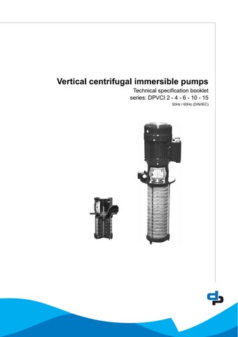
Vertical centrifugal immersible pumps
Technical specification booklet
series: DPVCI 2 - 4 - 6 - 10 - 15
50Hz / 60Hz (DIN/IEC)
Table of Contents
1Pump introduction
1.1General..................................................................................................................................................5
1.2Model key...............................................................................................................................................5
1.3Operation...............................................................................................................................................5
1.4Measuring, draining and venting............................................................................................................5
1.5Working range........................................................................................................................................6
1.6Basic material variants...........................................................................................................................7
1.7Pump bearing.........................................................................................................................................7
1.8Modular selection...................................................................................................................................7
1.9Approval.................................................................................................................................................7
2Performance characteristics
2.1Performance range 50Hz.......................................................................................................................8
2.2Performance range 60Hz.......................................................................................................................8
2.3Performance curve details.....................................................................................................................9
2.4Minimum efficiency index.......................................................................................................................9
2.5Performance with variable frequency drive............................................................................................9
2.6How to read the values from the curves..............................................................................................10
3Curves and dimensions
3.1Hydraulic performance curve DPVCI 2 B - 50Hz -2 pole.....................................................................12
3.2DPVCI 2 B - 50Hz - 2 pole - DIN..........................................................................................................13
3.3Hydraulic
3.4DPVCI 4 B - 50Hz - 2 pole - DIN..........................................................................................................15
3.5Hydraulic performance curve DPVCI 6 B - 50Hz - 2 pole....................................................................16
3.6DPVCI 6 B - 50Hz - 2 pole - DIN..........................................................................................................17
3.7Hydraulic performance curve DPVCI 10 B - 50Hz - 2 pole..................................................................18
3.8DPVCI 10 B - 50Hz - 2 pole - DIN........................................................................................................19
3.9Hydraulic performance curve DPVCI 15 C - 50Hz - 2 pole..................................................................20
3.10DPVCI 15 C - 50Hz - 2 pole - DIN.......................................................................................................21
3.11Hydraulic performance curve DPVCI 2 B - 60Hz -2 pole.....................................................................22
3.12DPVCI 2 B - 60Hz - 2 pole - DIN..........................................................................................................23
3.13Hydraulic performance curve DPVCI 4 B - 60Hz - 2 pole....................................................................24
3.14DPVCI 4 B - 60Hz - 2 pole - DIN..........................................................................................................25
3.15Hydraulic performance curve DPVCI 6 B - 60Hz - 2 pole....................................................................26
3.16DPVCI 6 B - 60Hz - 2 pole - DIN..........................................................................................................27
3.17Hydraulic performance curve DPVCI 10 B - 60Hz - 2
3.18DPVCI 10 B - 60Hz - 2 pole - DIN........................................................................................................29
3.19Hydraulic performance curve DPVCI 15 C - 60Hz - 2 pole..................................................................30
3.20DPVCI 15 C - 60Hz - 2 pole - DIN.......................................................................................................31
4Seals
4.1Mechanical seal option specifications..................................................................................................32
5Motors and motor options
5.1General................................................................................................................................................33 5.2Options.................................................................................................................................................33
5.3Standard motor data 2P 50Hz.............................................................................................................34
5.4Standard motor data 2P 60Hz.............................................................................................................35
6Materials
6.1Parts overview.....................................................................................................................................36
1Pump introduction
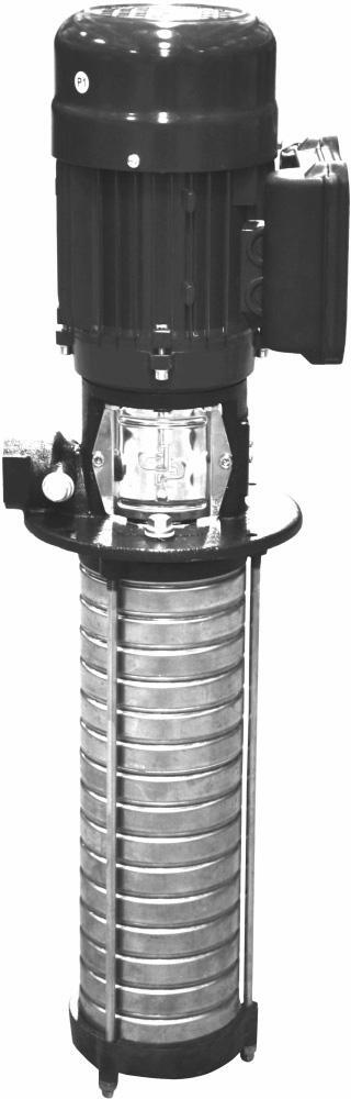
1.1General
The vertical, single or multi-stage centrifugal immersible pump series is designed for pumping water, filtered cooling fluids or lightly aggressive, watery mediums from a storage tank. The suction side at the bottom of the pump is equipped with a stainless steel strainer. The discharge side is located at the motor stool.
Where the required duty point corresponds with the amount of stages, in some applications the immersible length has to diver from this. Therefore it is possible for the DPVCI range to use empty stages to create the required length. In that case the impellers are mounted in the casings closest to the suction casing.
The hydraulic assembly is driven by an electric motor. All hydraulic parts of the pump are made of stainless steel.
1.2Model key
Table 1: Model key Example DPVCI 10/8(18) B
DP VCI 10 /8 (18) B
LabelDP
Material VCI
10
Product Label
Cast Iron suction casing and motor stool, 1.4301 / AISI 304 hydraulics
Appr. capacity in m3/h at Qopt /8
Number of impellers
(18)Total number of stages
B/CDesign version
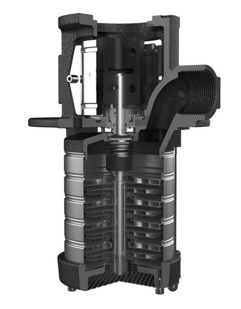
1.3Operation
During centrifugal operation of the pump an negative pressure is created at the inlet of the first impeller. This negative pressure enables the medium to enter the pump at the suction connection at the bottom of the pump. Every impeller is placed in a stage casing. The passage of this stage determines the capacity of the pump. The diameter of the stages is related to the centrifugal forces and its “stage pressure”: the more stages, the more pressure. This total capacity and raised pressure will be guided to the outside of the pump at the motor stool.
1.4Measuring, draining and venting
The pump is provided with plugs for measuring and venting, both located at the pump outlet connection. These connections are meant to vent the pump system when the pump is not in operation or to measure the discharge pressure of the pump using a G 1/4 connection. Also on the motor stool two connections are available to vent the storage tank.
DPVCI
1.5Working range
The working range is depending on the application and the combination of pressure and temperature. For specific and detailed limits please consult the working ranges as described in the paragraph 1.8. The overall working range of the pumps can be summarised as follows:
Table 2: Specification of the working range
Pump
Ambient temperature [°C]-20 up to 40 1
Minimum inlet pressureNPSHreq. + 1m
Viscosity [cSt] 1-100 2
Density [kg/m3] 1000-2500 2
Cooling forced motor cooling 3
Minimum frequency [Hz] 30
Maximum frequency [Hz] 60 4
Allowable size of solids pumped 5µm to 1mm
1.If the ambient temperature exceeds the above value or the motor is located more than 1000 m above sea level, please see 1.5.3
2.Deviation in viscosity and/or density could require an adapted motor power. Please contact your supplier for more detailed advice.
3.The free space above the motor cooling fan must be at least 1/4 of the diameter of the inlet of the cooling fan in order to have a sufficient flow of (cooling) air.
4.Pumps that are intended for 50 Hz operation, may not be connected to 60 Hz power supply.
1.5.1Minimum capacity
For minimum capacity at medium temperature of 20°C, see table 3: for higher temperatures, see table 4.
A minimum capacity has to be secured to prevent the pump from overheating, gathering gas, cavitation etc. The minimum capacity corresponds to all percentage of the optimum flow Qopt in relation to the temperature of the liquid pumped. Also a minimum medium level needs to be taken into consideration.
Table 3: Minimum capacity (Qmin)
Table 4: Minimum capacity vs.temperature (in % of Q optimum)
1.5.2Minimum fluid level
For ambient fluid conditions the minimum fluid level for the pumps in the storage tank is mentioned at the dimensions pages. In case of an increased required vapour pressure for fluids at higher operation temperatures, a system analyses is recommended to determine the required NPSH to avoid cavitation and air enclosure inside the pump.
1.5.3Ambient temperature and higher altitude
If the ambient temperature exceeds the maximum allowed value, or if the motor is located more than 1000 m above sea level, the motor cooling is less effective and could require an adapted motor power. See below table for the change in power output or contact your supplier for more detailed advice.
Table 5: Increase of required motor power
1.6Basic material variants
Table 6: Basic material variants
Model Hydraulic Casing Sealing
VC 1.4301JL1040 1EPDM
1.see medium handled list for correct seal material
1.7Pump bearing
Medium lubricated stage bearing Tungsten Carbide against Ceramic
1.8Modular selection
To suit almost every application the pump is assembled out of modules which can be selected depending on the required working range.
Basic modules are:
• Basic pump model, which defines the capacity, pressure and basic material.
Temperature range -20 up to 120°C
• Total stages, which defines the length of the pump suitable for the storage tank.
• Sealing, which define the elastomers and the mechanical seal. A cartridge seal construction is equipped as default. Temperature and pressure range, see chapter 4.1
• Electric motor, which defines all requirements of the motor such as motor size, power, voltage, frequency and all possible motor accessories.
For assembling the total amount of stages to the motor stool an additional upper stage casing is required. therefore when all visible stage stages are counted from the hydraulics, the sum will be the total amount of stages added by 1.
1.9Approval
CE Conformity with European Safety Directive
3Curves and dimensions
Förderhöhe TDH Hauteur Prevalenza Opvoerhoogte Altura
2/302,2kW
2/282,2kW
2/262,2kW
2/242,2kW
2/222,2kW
2/201,5kW
2/181,5kW
2/161,5kW
2/141,1kW
2/121,1kW
2/111,1kW
2/100,75kW
2/90,75kW
2/80,55kW
2/70,55kW
2/60,55kW
2/50,37kW
2/40,37kW
2/30,37kW
2/20,37kW
Leistungsbedarf PowerInput Puiss.abs. Potenzaass. Opgenomen vermogen Potencianec.0.0
=Fördermenge/Flow/Débit/Portata/Capaciteit/Caudal 1000.0kg/m³20090370-E/0
Figure 5: Performance curve DPVCI 2 B - 50Hz - 2 pole
3.2DPVCI 2 B - 50Hz - 2 pole - DIN
To determine the correct length of the pump see both following explanation and table.
Pump with empty stagesF3 + F4
Table 8: General dimensions length incl.
The length F3 corresponds with the length of the applied motor power. F4 corresponds with the total number of stages. Example: 2/16(30) F3=396mm, F4=732mm.
packing
2/2(2)PN100,3713410721944522631513014
2/3(3) 0,3713410721946624731515114
2/4(4) 0,3713410721948826931517314
2/5(5) 0,3713410721950929031519415
2/6(6) 0,5513410724355531233921617
2/7(7) 0,5513410724357633333923717
2/8(8) 0,5513410724359835533925918
2/9(9) 0,7515011523462038634028020
2/10(10) 0,7515011523464240834030220
2/11(11) 1,115011526469342937032323
2/12(12) 1,115011526471545137034523
2/14(14)PN251,115011526475849437038824
2/16(16) 1,517614128082754739643129
2/18(18) 1,517614128087059039647429
2/20(20) 1,517614128091363339651730
2/22(22) 2,217614128095667639656035
2/24(24) 2,217614128099971939660336
2/26(26) 2,2176141280104276239664636
2/28(28) 2,2176141280108580539668937 2/30(30) 2,2176141280112884839673238
3.3Hydraulic performance curve DPVCI 4 B - 50Hz - 2 pole
Förderhöhe TDH
Hauteur
Prevalenza Opvoerhoogte Altura
4/185,5kW
4/165,5kW
4/144,0kW
4/124,0kW
4/113,0kW
4/103,0kW
4/93,0kW
4/82,2kW
4/72,2kW
4/61,5kW
4/51,5kW
4/41,1kW
4/30,75kW
4/20,55kW
012345678
Leistungsbedarf PowerInput Puiss.abs. Potenzaass. Opgenomen vermogen Potencianec.0.0
012345678 [m³/h]
=Fördermenge/Flow/Débit/Portata/Capaciteit/Caudal 1000.0kg/m³20090373-E/0
Figure 6: Performance curve DPVCI 4 B - 50Hz - 2 pole
3.4DPVCI 4 B - 50Hz - 2 pole - DIN
To determine the correct length of the pump see both following explanation and table.
Pump with empty stagesF3 + F4 F3 + F4 -LB
The length F3 corresponds with the length of the applied motor power. F4 corresponds with the total number of stages. Example: 4/16(22) F3=442mm, F4=560mm.
Table 9: General dimensions length incl.
*including packing
4/2(2)PN100,3713410721944522631613014
4/3(3) 0,5513410724349024733915116
4/4(4) 0,5513410724351226933917316
4/5(5) 0,7515011523453430034019419
4/6(6) 1,115011526458632237021621
4/7(7) 1,115011526460734337023722
4/8(8) 1,517614128065537539625926
4/9(9) 1,517614128067639639628026 4/10(10) 1,517614128069841839630226
4/11(11) 2,217614128071943939632330
4/12(12)PN252,217614128074146139634530 4/14(14) 2,217614128078450439638831
4/16(16) 319514531687355744243143
4/18(18) 319514531691660044247443
4/20(20) 319514531695964344251744
4/22(22) 4223167324101068645056054
4/24(24) 4223167324105372945060355
4/26(26) 4223167324109677245064672
4/26(28) 4223167324113981545068974
4/26(30) 4223167324118285845073274
3.5Hydraulic performance curve DPVCI 6 B - 50Hz - 2 pole
Förderhöhe TDH
01020304 [US.gpm]0 010203 [IM.gpm]0
6/265,5kW
6/245,5kW
6/225,5kW
6/205,5kW
6/184,0kW
6/164,0kW
6/143,0kW
6/123,0kW
6/113,0kW
6/102,2kW
6/92,2kW
6/82,2kW
6/71,5kW
6/61,5kW
6/51,1kW
6/41,1kW
6/30,75kW
6/20,37kW
Hauteur Prevalenza Opvoerhoogte Altura 024681 [m³/h]0
0.00.51.01.52.02.5 [l/s]
Leistungsbedarf PowerInput Puiss.abs. Potenzaass. Opgenomen vermogen Potencianec.0.0
=Fördermenge/Flow/Débit/Portata/Capaciteit/Caudal 1000.0kg/m³20090374-E/0
Figure 7: Performance curve DPVCI 6 B - 50Hz - 2 pole
3.6DPVCI 6 B - 50Hz - 2 pole - DIN
To determine the correct length of the pump see both following explanation and table.
Table 10: General dimensions length incl.
The length F3 corresponds with the length of the applied motor power. F4 corresponds with the total number of stages. Example: 6/12(26) F3=442mm, F4=740mm.
packing
6/2(2)PN100,3713410721945523631614014
6/3(3) 0,7515011523450527134016518
6/4(4) 1,115011526456029637019021
6/5(5) 1,115011526458532137021521
6/6(6) 1,517614128063635639624025
6/7(7) 1,517614128066138139626526
6/8(8) 2,217614128068640639629029
6/9(9) 2,217614128071143139631529
6/10(10) 2,217614128073645639634030
6/11(11)PN25319514531680749144236541
6/12(12) 319514531683251644239042
6/14(14) 319514531688256644244042
6/16(16) 422316732494061645049052
6/18(18) 422316732499066645054053
6/20(20) 5.5266178329112179253159088
6/22(22) 5.5266178329117184253164089
6/24(24) 5.5266178329122189253169090
6/26(26) 5.5266178329127194253174091
6/26(28) 5.5266178329132199253179091
6/26(30) 5.52661783291371104253184092
3.7Hydraulic performance curve DPVCI 10 B - 50Hz - 2 pole
Förderhöhe TDH
Hauteur Prevalenza Opvoerhoogte Altura
10/217,5kW
10/197,5kW
10/114kW
10/104kW
10/94kW
10/83kW
10/73kW
10/62,2kW
10/52,2kW
10/41,5kW
10/31,1kW
10/20,75kW
10/10,75kW
Leistungsbedarf PowerInput Puiss.abs. Potenzaass. Opgenomen vermogen Potencianec.0.0
=Fördermenge/Flow/Débit/Portata/Capaciteit/Caudal 1000.0kg/m³20101080-A/0
Figure 8: Performance curve DPVCI 10 B - 50Hz- 2 pole
3.8DPVCI 10 B - 50Hz - 2 pole - DIN
To determine the correct length of the pump see both following explanation and table.
The length F3 corresponds with the length of the applied motor power. F4 corresponds with the total number of stages. Example: 10/8(13) F3=455mm, F4=445mm.
Table 11: General dimensions
packing
2,217614128068640639928737 10/7(7) 319514531673241645531347 10/8(8) 319514531675844244531348
10/9(9)PN25422316732479246845333958
10/10(10) 422316732481949545336658 10/11(11) 422316732484552145339259
10/13(13) 5,526617832998465553944593
10/15(15) 5,5266178329103770853949894
10/17(17) 7,52661783771138761587551127
10/19(19) 7,52661783771191814587604129 10/21(21) 7,52661783771244867587657130
3.9Hydraulic performance curve DPVCI 15 C - 50Hz - 2 pole
Förderhöhe TDH
Hauteur Prevalenza Opvoerhoogte Altura
020406080100 [US.gpm]
020406080 [IM.gpm]
7.5kW15/118
5kW15/115
3kW15/115
1kW15/111
0kW15/111
9W15/11k
15/811/7k
15/77.5kW
5.5*W7.5/15/6k
15/55.5kW W15/44k
15/33kW
2.215/2kW
15/11.1kW
Leistungsbedarf PowerInput Puiss.abs. Potenzaass. Opgenomen vermogen Potencianec.
=Fördermenge/Flow/Débit/Portata/Capaciteit/Caudal 1000.0kg/m³20210121-/0
Figure 9: Performance curve DPVCI 15 C - 50Hz - 2 pole
3.10DPVCI 15 C - 50Hz - 2 pole - DIN
To determine the correct length of the pump see both following explanation and table.
with empty
Table 12: General dimensions length incl.
The length F3 corresponds with the length of the applied motor power. F4 corresponds with the total number of stages. Example: 15/3(15) F3=445mm, F4=498mm.
*including packing
15/1(2)PN101,115011526457831439418427
15/2(2) 2,220024828160532442118438
15/3(3) 321515731769237546722547
15/4(4) 424816835677241650626657
15/5(5) 5,528819743297053866330798
15/6(6) 5,5 1
15/6(6) 7,52881974321011579663348100
15/7(7)PN167,5 2881974321052620663389101
15/8(8) 7,5 1 2881974321193661663430163
15/8(8) 113402235331194661764430163
15/9(9) 113402235331235702764471185
15/10(10) 113402235331276743764512187
15/11(11) 113402235331317784764553188
15/13(13) 153402235331399866764635201
15/15(15)PN25153402235331481948764717204
15/17(17) 18,534022353315631030764799217
1.Decreased power 2881974321011579663307100
3.11Hydraulic performance curve DPVCI 2 B - 60Hz -2 pole
051015 [US.gpm]
051015 [IM.gpm]
2/223,0kW
2/203,0kW
2/182,2kW
2/162,2kW
2/142,2kW
Förderhöhe TDH
Hauteur
Prevalenza
Opvoerhoogte Altura
2/121,5kW
2/111,5kW
2/101,5kW
2/91,1kW
2/81,1kW
2/71,1kW
2/60,75kW
2/50,75kW 2/40,55kW 2/30,37kW 2/20,37kW
0.00.51.01.52.02.53.03.54.0 [m³/h]
0.00.20.40.60.81.0 [l/s]
Leistungsbedarf PowerInput Puiss.abs. Potenzaass. Opgenomen vermogen Potencianec.
0.00.51.01.52.02.53.03.54.0 [m³/h]
=Fördermenge/Flow/Débit/Portata/Capaciteit/Caudal 1000.0kg/m³20090371-E/0
Figure 10: Performance curve DPVCI 2 B - 60Hz - 2 pole
3.12DPVCI 2 B - 60Hz - 2 pole - DIN
To determine the correct length of the pump see both following explanation and table.
with empty
Table 13: General dimensions length incl.
The length F3 corresponds with the length of the applied motor power. F4 corresponds with the total number of stages. Example: 2/3(22) F3=315mm, F4=560mm.
*including packing
2/2(2)PN100,3713410721944522631513014
2/3(3) 0,3713410721946624731515114
2/4(4) 0,5513410724351226933917316
2/5(5) 0,7515011523453430034019418
2/6(6) 0,7515011523455632234021619
2/7(7) 1,115011526460734337023722
2/8(8) 1,115011526462936537025922
2/9(9) 1,115011526465038637028022
2/10(10)PN251,517614128069841839630226
2/11(11) 1,517614128071943939632327
2/12(12) 1,517614128074146139634527
2/14(14) 2,217614128078450439638831
2/16(16) 2,217614128082754739643132
2/18(18) 2,217614128087059039647432
2/20(20) 319514531695964344251744
2/22(22) 3195145316100268644256045
2/22(24) 3195145316104572944260345
2/22(26) 3195145316108877244264645
2/22(28) 3195145316113181544268946
2/22(30) 3195145316117485644273264
3.13Hydraulic performance curve DPVCI 4 B - 60Hz - 2 pole
Förderhöhe TDH
4/185,5kW
4/165,5kW
4/144,0kW
4/124,0kW
4/113,0kW
4/103,0kW
4/93,0kW
4/82,2kW
Hauteur Prevalenza Opvoerhoogte Altura 012345678
4/72,2kW
4/61,5kW
4/51,5kW
4/41,1kW
4/30,75kW
4/20,55kW
Leistungsbedarf PowerInput Puiss.abs. Potenzaass. Opgenomen vermogen Potencianec.0.0
=Fördermenge/Flow/Débit/Portata/Capaciteit/Caudal 1000.0kg/m³20090373-E/0
Figure 11: Performance curve DPVCI 4 B - 60Hz - 2 pole
3.14DPVCI 4 B - 60Hz - 2 pole - DIN
To determine the correct length of the pump see both following explanation and table.
Pump with empty stagesF3 + F4
Table 14: General dimensions length incl.
The length F3 corresponds with the length of the applied motor power. F4 corresponds with the total number of stages. Example: 4/7(16) F3=396mm, F4=431mm.
packing
4/2(2)PN100,5513410724346922633913016
4/3(3) 0,7515011523449125734015118 4/4(4) 1,115011524354327937017321 4/5(5) 1,517614126459031039619425 4/6(6)
4/7(7) 2,217614128063335339623728 4/8(8) 2,217614128065537539625929 4/9(9)PN25319514531672240644228040 4/10(10) 319514531674442844230241 4/11(11) 319514531676544944232341 4/12(12) 422316732479547145034550 4/14(14) 422316732483851445038851
4/16(16) 5,526617832996263353143184
4/18(18) 5,5266178329100567653147485
4/18(20) 5,5266178329104871953151785
4/18(22) 5,5266178329109176253156088
4/18(24) 5,5266178329113480553160388
4/18(26) 5,5266178329117784853164689
4/18(28) 5,5266178329122089153168989
4/18(30) 5,5266178329126393453173289
3.15Hydraulic performance curve DPVCI 6 B - 60Hz - 2 pole
Förderhöhe TDH
Hauteur Prevalenza Opvoerhoogte Altura
6/187,5kW
6/167,5kW
6/145,5kW
6/125,5kW
6/114,0kW
6/104,0kW
6/94,0kW
6/83,0kW
6/73,0kW
6/62,2kW
6/52,2kW
6/41,5kW
6/31,1kW
6/20,75kW
6/10,37kW
Leistungsbedarf PowerInput Puiss.abs. Potenzaass. Opgenomen vermogen Potencianec.0.0
Figure 12: Performance curve DPVCI 6 B - 60Hz - 2 pole
3.16DPVCI 6 B - 60Hz - 2 pole - DIN
To determine the correct length of the pump see both following explanation and table.
Pump with empty stagesF3 + F4
Table 15: General dimensions length incl.
The length F3 corresponds with the length of the applied motor power. F4 corresponds with the total number of stages. Example: 6/2(18) F3=340mm, F4=540mm.
packing
6/2(2)PN100,7515011523448024634014017
6/3(3) 1,115011516453527137016520
6/4(4) 1,517614128058630639619024
6/5(5) 2,217614128061133139621528
6/7(7) 319514531670739144226539
6/8(8)PN25319514531673241644229040
6/9(9) 422316732476544145031549
6/10(10) 422316732479046645034050
6/11(11) 422316732481549145036550
6/12(12) 5,526617832992159253139083
6/14(14) 5,526617832997164253144084
6/16(16) 7,52661783771069692579490116
6/18(18) 7,52661783771119742579540117
6/18(20) 7,52661783771169792579590117
6/18(22) 7,52661783771219842579640117
6/18(24) 7,52661783771269892579690118
6/18(26) 7,52661783771319942579740118
6/18(28) 7,52661783771369992579790118
6/18(30) 7,526617837714191042579840119
Förderhöhe TDH
Hauteur
Prevalenza
Opvoerhoogte Altura
10/1511kW
10/1311kW
10/117,5kW
10/107,5kW
10/97,5kW
10/85,5kW
10/75,5kW
10/64kW
10/54kW
10/43kW
10/32,2kW
10/21,5kW
10/10,75kW
Leistungsbedarf PowerInput Puiss.abs. Potenzaass. Opgenomen vermogen Potencianec.0
=Fördermenge/Flow/Débit/Portata/Capaciteit/Caudal 1000.0kg/m³20101081-B/0
Figure 13: Performance curve DPVCI 10 B - 60Hz- 2 pole
3.18DPVCI 10 B - 60Hz - 2 pole - DIN
To determine the correct length of the pump see both following explanation and table.
The length F3 corresponds with the length of the applied motor power. F4 corresponds with the total number of stages. Example: 10/1(6) F3=343mm, F4=287mm.
Table 16: General dimensions
422314132474041645328756 10/7(7)PN255,526617832982649753928771 10/8(8) 5,526617832985252353931372 10/9(9) 7,5266178377926549587339119
10/10(10) 7,5266178377953576587366120 10/11(11) 7,5266178377979602587392121
10/13(13) 113152044981183685738445178
10/15(15) 113152044981236738738498179
10/15(17) 113152044981289791738551183
10/15(19) 113152044981342844738604184 10/15(21) 113152044981395897738657184
3.19Hydraulic
performance curve DPVCI 15 C - 60Hz - 2 pole
8.5W11k15/1
108.5kW15/1
1515/9kW
1515/8kW
1515/7kW
Förderhöhe TDH
Hauteur
Prevalenza Opvoerhoogte Altura
Leistungsbedarf PowerInput Puiss.abs. Potenzaass. Opgenomen vermogen Potencianec.
15/611kW
5kW15/11
7.515/4kW
5kW5.15/3k
15/24kW
1kW15/2.2 *Power input based on a V 15/3 C of this hydraulic speed design
=Fördermenge/Flow/Débit/Portata/Capaciteit/Caudal 1000.0kg/m³20210122-B/1
Figure 14: Performance curve DPVCI 15 C - 60Hz - 2 pole
3.20DPVCI 15 C - 60Hz - 2 pole - DIN
To determine the correct length of the pump see both following explanation and table.
Pump with empty stagesF3 + F4
Table 17: General dimensions length incl.
The length F3 corresponds with the length of the applied motor power. F4 corresponds with the total number of stages. Example: 15/4(11) F3=587mm, F4=392mm.
*including packing
15/1(2)PN102,220014828160532442118437
15/2(2) 424816835669033450618453
15/3(3) 5,528819743288845666322585
15/4(4) 7,528819743292949766326686
15/5(5)PN16113402235331071538764307157
15/6(6) 113402235331112579764348158
15/7(7) 153402235331153620764389170
15/8(8)PN25153402235331194661764430170
15/9(9) 153402235331235702764471193
15/10(10) 18,53402235331276743764512204
15/11(11) 18,53402235331317784764553204
15/11(13) 18,53402235331399866764635205
15/11(15) 18,53402235331481948764717206
15/11(17) 18,534022353315631030764799207
5Motors and motor options
5.1General
The standard DP motors are produced conform the latest technical design, and comply with the international standards and EU directives regarding safety measures.
The motors can be specified as:
• Standard IE3 >= 0,75kW
• T.E.F.C. (totally enclosed fan cooled) Squirrel cage.
• AC induction motor.
• Protection IP55.
• Insulation class F.
• Temperature rise class B.
• Duty class S3 (50% or S4 (40%), maximum starts per hour, see motor tables).
• Noise levels conform IEC 60034-9.
• >= 3,0 kW default 3 x PTC.
The motors come in 2 different configurations depending on power rate. Up to 4kW a V18 mounting type is used. For power 5,5kW and up a flanged motor type V1 is default. Mounting in acc. with IEC60034-7 and dimensions in acc. with IEC 60072-1
5.2Options
• Standard motors as per above, in single phase (1x230V)upto and including 2,2kW.
• Provided with 10 pole industrial connector “Harting stecker” HAN 10, mounted in stead of the motor connection box, <= 7,5kW.
• Provided with Rain cover on top of the fan hood.
• For motors < 3kW provided with 3 x PTC and/or anti condensation heater (1x230V).
• Motors from other manufacturers like Siemens and VEM.
5.3Standard motor data 2P 50Hz
Table 18: Motor data 1 and 3 phase, 2p 50Hz
Article
37000000030.371x2302.63.70.9210%275067581xM18x1.520
37000000050.551x2303,693.90.9210%276070561xM18x1.520
37000000070.751x2305 3.90.9510%278070561xM20x1.520
37000000111.11x2306.684.30.9510%279075581xM20x1.520
37000000151.51x2308.994.80.9510%280076581xM20x1.520
37000000222.21x23013.044.80.7610%280077 581xM20x1.520
37270110030.37230/4001.6/0.954.50.7610%286576 601xM20x1.5300
37270110050.55230/4002.1/1.25.30.8010%288082 601xM20x1.5300
37100510070.75230/4003.1/1.86.60.8210%288080.7 551xM20x1.5300
37100510111.1230/4004.0/2.36.90.8110%288084 551xM20x1.5300
37160510151.5230/4005.3/3.07.30.8610%292584.2 551xM20x1.5300
37160510222.2230/4007.5/4.380.8510%291085.9551xM20x1.5300
37161510303230/40010.2/5.89.30.8510%292087.1 572xM20x1.5300
37161520303400/6905.8/3.39.30.8910%292087.1 572xM20x1.5300
37161510404230/40012.8/7.48.40.8910%293088.1 582xM20x1.5300
37161520404400/6907.4/4.38.40.8910%293088.1582xM20x1.5300
37161510555.5230/40017.3/108.80.8910%294089.2 632xM25x1.5300
37161520555.5400/69010/5.88.80.8910%294089.2632xM25x1.5300
37161510757.5230/40023/13.39.20.8910%294090.1 632xM25x1.5300
37161520757.5400/69013.3/7.79.20.910%294090.1 632xM25x1.5300
371415111011230/40033.4/19.37.30.910%294591.2 692xM32x1.5300
371415211011400/69019.3/11.27.30.8510%294591.2692xM32x1.5300
371415115015230/40049.0/28.27.60.8510%294590.3702xM32x1.5200
371415215015400/69028.2/16.37.60.910%294590.3702xM32x1.5200
371415118518.5230/40055.6/32.17.70.910%294092.4692xM32x1.5200
371415218518.5400/69032.1/18.67.70.8810%294092.4692xM32x1.5200
371015122022230/40068.7/39.57.50.8810%294591.3752xM32x1.5200
371015222022400/69039.5/22.97.50.910%294591.3 752xM32x1.5200
5.4Standard motor data 2P 60Hz
Table 19: Motor data 3 phase, 2p 60Hz
37270110030.37230/4001.6/0.954.50.76+20%.-10%343076,0601xM20x1.5300
37270110050.55230/4002.1/1.25.30.80+20%.-10%346082,0 601xM20x1.5300
37100510070.75230/4002.8/1.66.20.88+25%/-10%346080.7 581xM20x1.5300
37100510111.1230/4004.2/2.46.80.9+25%/-10%344082.5601xM20x1.5300
37160510151.5230/4005.0/2.96.90.9+25%.-10%351085.5 581xM20x1.5300
37160510222.2230/4007.1/4.17.70.9+25%/-10%349086.5 581xM20x1.5300
37161510303230/4009.6/5.57.60.91+25%/-10%349587.5 612xM20x1.5300
37161520303400/6905.6/3.27.60.91+25%.-10%349587.5612xM20x1.5300
37161510404230/40012.5/7.280.92+25%/-10%351588.5622xM20x1.5300
37161520404400/6907.2/4.280.92+25%/-10%351588.5 622xM20x1.5300
37161510555.5230/40017/9.87.80.93+25%.-10%352588.5672xM25x1.5300
37161520555.5400/6909.8/5.67.80.93+25%/-10%352588.5672xM25x1.5300
37161510757.5230/40022.5/13.080.92+25%/-10%352589.5672xM25x1.5300
37161520757.5400/69013.0/7.580.92+25%/-10%352589.5672xM25x1.5300
371415111011230/40032.9/19.06.30.92+25%/-10%353091.0 732xM32x1.5300
371415211011400/69019.0/11.06.30.92+25%.-10%353091.0 732xM32x1.5300
371415115015230/40044.3/25.66.50.92+25%/-10%353092.2732xM32x1.5200
371415215015400/69025.6/14.86.50.92+25%/-10%353092.2732xM32x1.5200
371415118518.5230/40054.6/31.56.70.91+25%.-10%352592.2732xM32x1.5200
371415218518.5400/69031.5/18.36.70.91+25%/-10%352592.2 732xM32x1.5200
371015122022230/40065.5/37.87.80.91+25%/-10%355092.2 792xM32x1.5200
371015222022400/69037.8/21.97.80.91+25%/-10%355092.2792xM32x1.5200