Oxford University Press, Inc., publishes works that further Oxford University's objective of excellence in research, scholarship, and education.
Oxford New York
Auckland Cape Town Dares Salaam Hong Kong Karachi Kuala Lumpur Madrid Melbourne Mexico City Nairobi New Delhi Shanghai Taipei Toronto
With offices in Argentina Austria Brazil Chile Czech Republic France Greece Guatemala Hungary Italy Japan Poland Portugal Singapore South Korea Switzerland Thailand Turkey Ukraine Vietnam
Copyright © 20 II by Oxford University Press, Inc.
Published by Oxford University Press, Inc. 198 Madison Avenue, New York, New York 10016 http://www.oup.com
Oxford is a registered trademark of Oxford University Press
All rights reserved. No part of this publication m11y be reproduced, stored in a retrieval system, or transmitted, in any form or by any means, electronic, mechanical, photocopying, recording, or otherwise, without the prior permission of Oxford University Press.
ISBN: 978-0-19-976570-6
Printing number: 9 8 7 6 S 4 3 2 I
Contents
Exercise Solutions (Chapters 1 - 16)
Problem Solutions (Chapters 1- 16)

Preface
This manual contains complete solutions for all exercises and end-of-chapter problems included in the book Microelectronic Circuits, International Sixth Edition, by Adel S. Sedra and Kenneth C. Smith.
We are grateful to Mandana Amiri, Shahriar Mirabbasi, Roberto Rosales, Alok Berry, Norman Cox, John Wilson, Clark Kinnaird, Roger King, Marc Cahay, Kathleen Muhonen, Angela Rasmussen, Mike Green, John Davis, Dan Moore, and Bob Krueger, who assisted in the preparation of this manual. We also acknowledge the contribution of Ralph Duncan and Brian Silveira to previous editions of this manual.
Communications concerning detected errors should be sent to the attention of the Engineering Editor, mail to Oxford University Press, 198 Madison Avenue, New York, New York, USA 10016 or e-mail to higher.education.us@oup.com. Needless to say, they would be greatly appreciated.
A website for the book is available at www.oup.com/sedra-xse
Exercise 1--1
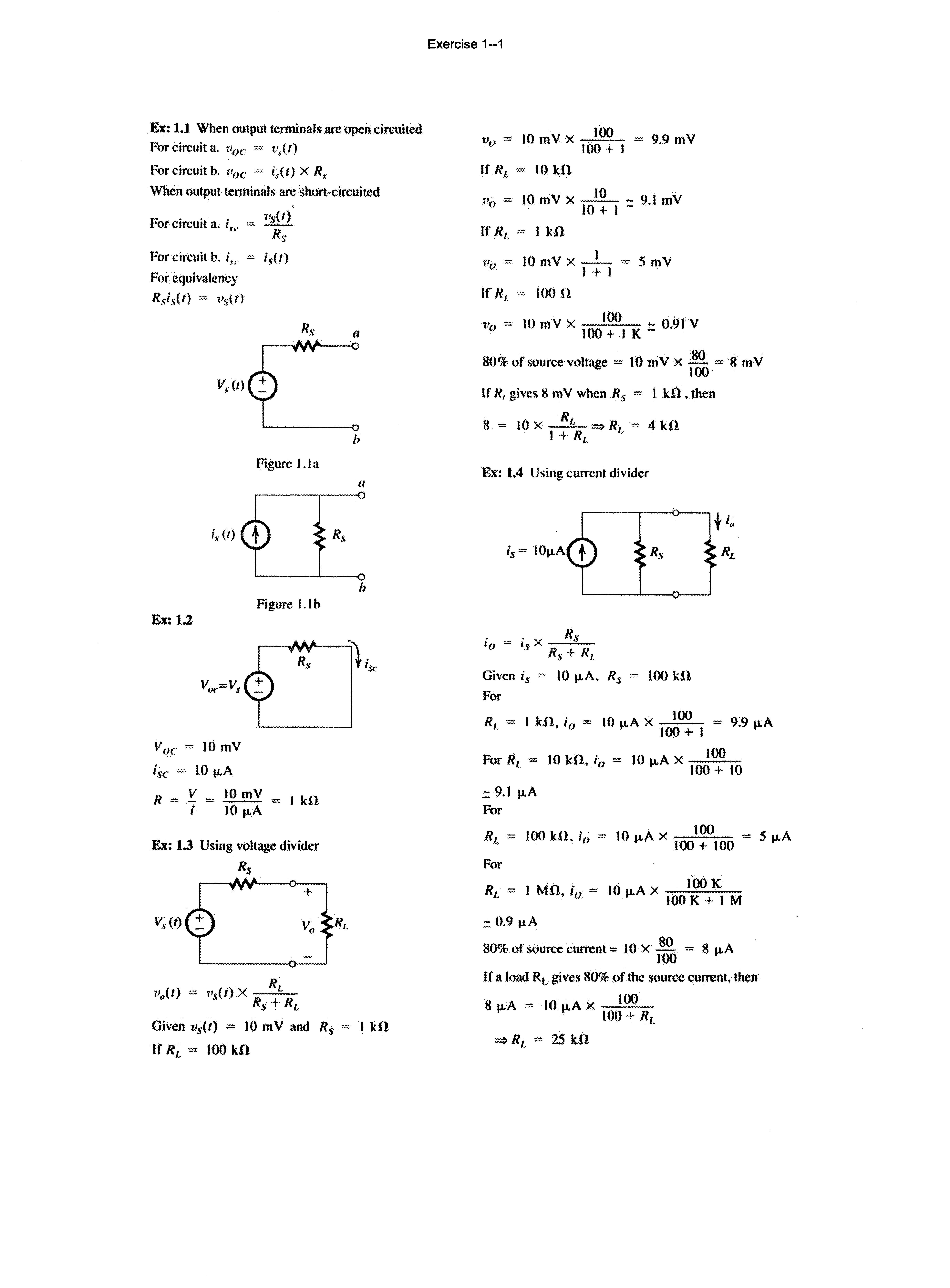
Ex: 1.1 When output terminals arc open circuited
For circuit a. n0 c = u,U)
For circuit b. l'oc (,(t) X R, When output tenninals arc short-circuited
.., "' .·or CJrcmt a. i ,..
For circuit b. f.,. i 5{ I)
For Rsis(t) ""' t•s<t)
V 0 c=10mV
isc '"' 10 tJ,A
R = IOmY kll i lO tJ,A
Ex: 1.3 Using voltage divider Rs
+
(/ b
v 0 10 mY X .....M!Q_ 9.9 mY 100 + l
If R, 10 kH
<'(J ·"" 10 mV X _!Q_ - 9.1 mY 10 +I-
If Rt."" lk!l
t'o = 10 mV X _I_ I+ I 5mY
If R ' 100 H I. 10 mY X _!QQ._ - 0.91 Y 100 +I K-
80% of source voltage = lO mV X 80 ""' 8 mY 100
If R, gives 8 mV when R5 = I k!1, then R 8 = ""'4kfl I+ R ' l.
J<:x: 1.4 Using current divider
R 11.,(1) ""' X -._tRs +
Given vs(t) = 10 mY and R5 1 kH
If 100 kfl
• X Rs 1o Is Rs + Rr
Given is " 10 tJ.A, Rs 100 .kU
For
Rt_ "" I kH, i 0 = 10 tJ.A X .....M!Q_ = 9.9 tJ.A 100+ I
For RL .., 10 kll, iu "" 10 1-1-A X 10
;: 9.1 1.1.A
For
Rr. "" 100 kH, i0 ''" 10 tJ,A X "'" 5 1-1-A
For R I M n 10 A X 100 K 1" "' ••· 10 = 100 K + I M
;: 0.9 1-1-A
80% of wurcc current = l 0 X 80 = 8 1-1-A 100
If a load Rt gives 80%ofthc source current, then 8 1-1-A ·"" 10 p.A X _I_()O 1.00+ R1
Figure I. Ia Figure l.lb Ex:i.2Ex: 1.5 f = "" ""' 1000 Hz T 10 -J
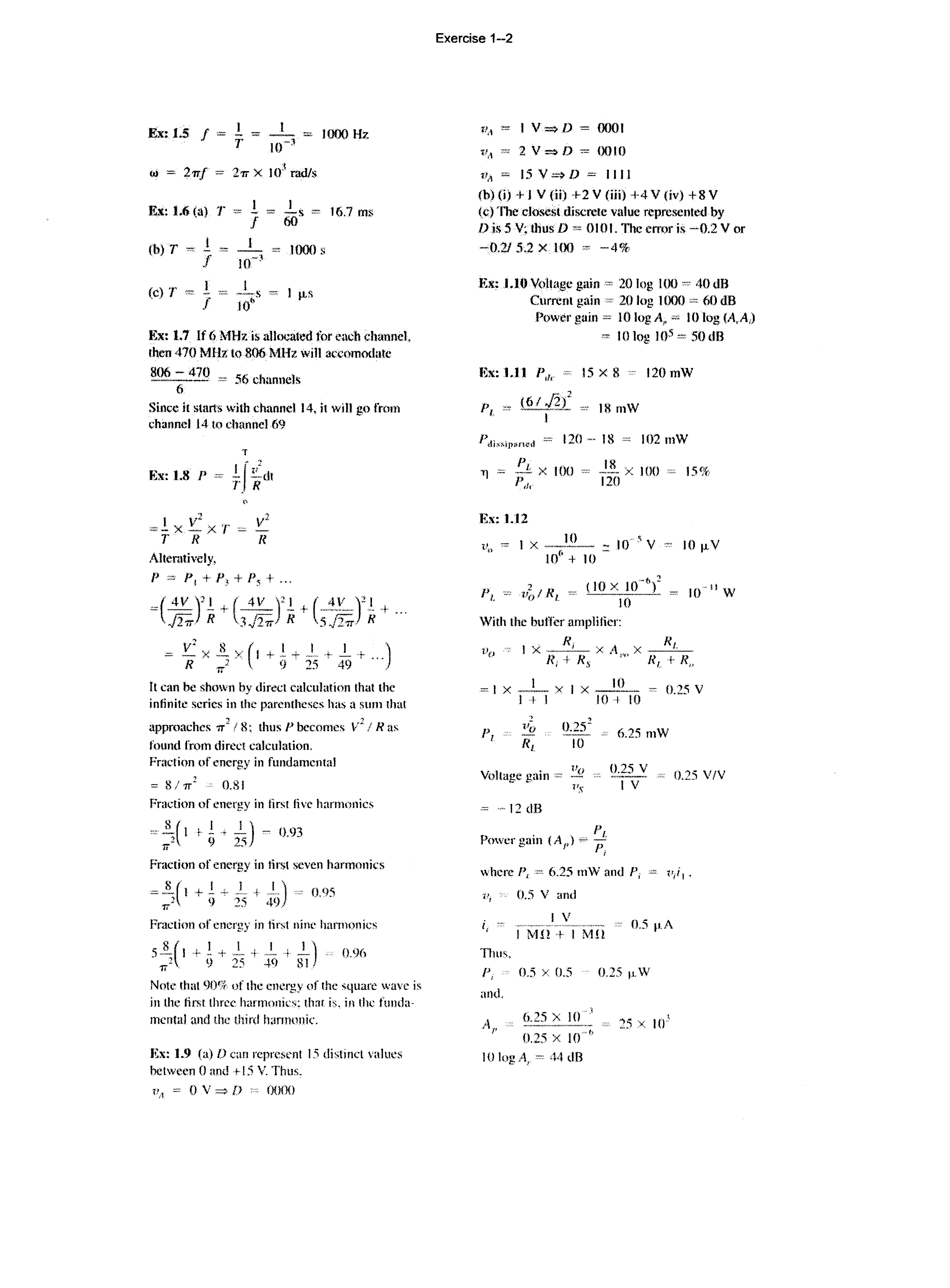
F..x: 1.6 (al T
(b) T ., I .f
I f I lfC:' 1000
(c) T "" l J j_s '" l !0"
I<:x: 1.7 If 6 MHz is allocated for ench channel. then 470 MHz to 806 MHz will accmnodate
806470 '' 56 chnnnels
6
Since it starts with channel 14. it will go from 14 to ehanncl69
·r I , .! .•• r. R p :cz PI+ P, + P, +
.. k ...
It can he shown by direct calculali<'ll that the infinite series in the parentheses h;ts a sum that approaches <T! i 8; thus P becomes V 1 ! R as found from dirCl'! calculation.
Frat·tion of energy in fundamental = 8/ 1r 2 O.SI
Fra<.;tion of energy in tirst live harmonics f l" .l)- 091 ;/ 9 25 .•
Fmetiun of in first seven harmonks
""Ji(l +.! ""'·) + '·') 9 25 4<) 0.95
Fra.:tion of energy in first nitw han non ics
s + ij + ;;5 + i 0.96
Noh: that <JI)•:;. of the energv of the square waw is in the lin<t three harmonic;: that h. in the fundamental and the third h;mnnnk.
Ex: 1.9 (a) lJ ean 15 distinct values hetween 0 anJ + 15 V. Thus.
l'.t = 0 V D 0000
Exercise 1--2
11.1 I V => D = 0001
1•.1 2 V => D "" 0010
15V=>D=IIII
(b) (i) +I V (ii) +2 V (iii} +4 V (iv) + 8 V
(e) The closest discrete value rep.rcsented by Dis 5 V; thus D OIOL TI1c error is -0.2 V or -0.21 5.2 X 100 -·4%
Ex: 1.10 Voltage gain '" 20 log 100 •·•· 40 dB
Current gain " 20 log 1000 "" 00 dB
Power gain 10 log A,. "' 10 log lA, A,) 10 log )()5"' 50 dB
120
18 102 mW X 100 15% 120
1.12 10 '
10
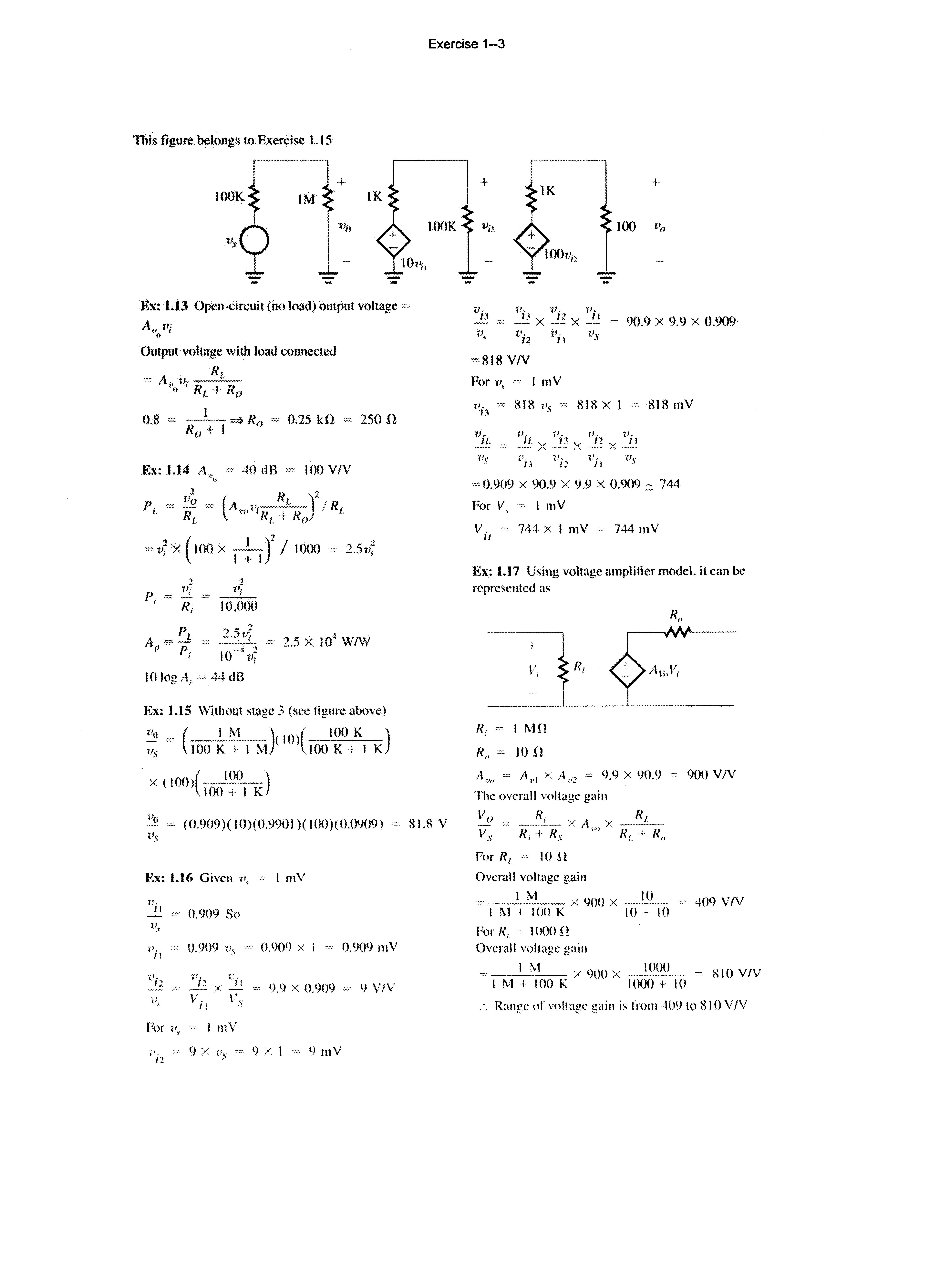
This figure belong,.Ho. ExerCise Ll5
r---1+
lOOK
Ex: U3 Open-circuit (no load) output voltage =
At'n''i
Output·voltnge with load connected
Rt "'· II; -.-- " R1 + R"
Exercise 1-3 + + 100 v,
I()()K
001!;2
- -=:- -
lf, fl, 11. Jl, _E ""· X _,!,! X ..!.! ""' 90.9 X 9. 9 X 0.909
v, vi2 vil Vs ""8l8V/V For t', .•., I mV
uh "'' 818 I's ., 818 X I = 818 mV
"' - 1-·- =» R0 '"' 0.25 k.O R0 + I
Ex: 1.14 A,.,. 40 dB ""' 100 V/V
p "' "" ('A t'·-.!!.!:_)2 r R
L RL '" 'RI. + Ro I.
250fl (1oo x - 1 -)2 I IIJOO 2.:hl,. ' I + I
IOlogA,,
Ex: 1.15 Without stage 3 (sec figure above)
"' ( I M )< IO)( 100 K )
u5 100 K l- I M 100 K + I K
X (100)(__Ji}Q_) IOO+IK
(0.909)(10)(0.9901 )( 100)(0.()<)09) RL8 V
"0.909 X 90.9 X 9.9 X 0.909::: 744
fur V,"' I mV
V. · 744 xI mV n 744 mV
t<:x: J.17 Usiilg voltage amplifier model.it can be represented as
Vs
Ex: 1.16 Given v, I mV
lf, 0 = 0.909 So
v,
0.909 lis = 0.909 X I ·"'· 0.909 mV
For u, , , 1 mV
1';2 9 X ·""· t) )( 1 9 mV
R; "" I MH
R,. = IOU
A'", = A,. 1 X A,.2 = 1),9 X 90.9
The overall voltage gain
Vo X A X __!!_L__
Vs R, + Rs '"' RL + R,
For R 1 10 H
Oventll voltage gain
...... X 900 X _J_O_
I M 1 100 K 10 ·' I()
For R, '' 1000 H
Overall voltage gain
R, 900 V!V 409 V/V
!_.1'-_i__ X 900 X - IOOO__ = R10 VIV
I M ! 100 K 1000 + 10
·. Range of voltage gain is from 409 to Ill 0 VIV
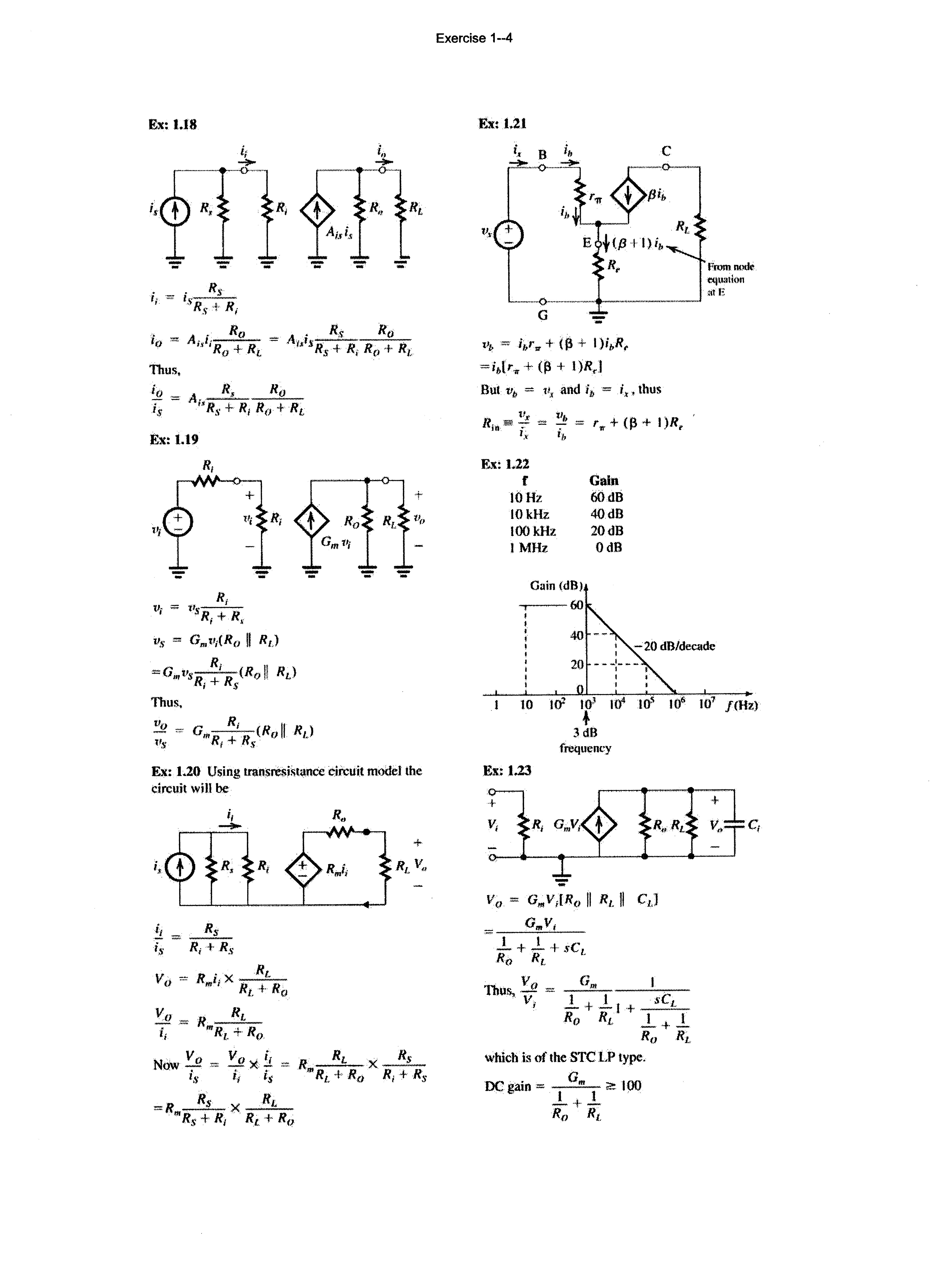
Ex:l.l8
Ex:t.l9 R, Rt ,,, "'t's-R1+ R, tis "" G,.t,1(R 0 II RE)
::O.,vs Rl Rs (Ro !1 RL)
111Ull.
tlo R, II - = O,.--.-(R 0 R1) tis R1 + Rs
Ex: 1.20 Using transresistance circuit model the circuit will be
Exercise 1--4
Ex:l.2l
···-·--··0·--··----·-···-G -
t'J, = ihr" + (13 + I )ivR, l)R,I
But vi> = 11, and ip = i., thus
K": 1.22 f 10Hz lOkHz lOOkHz I MHz
Gain 60dB 40dB 20dB OdB Gain !dB)
to t<¥ 103 t04
Ex.: 1.23
!1 ___!L is R, -1· Rs
v) R 1 '"' R ·+· R I. 0
Vo .""' R ....i!L_
i1 "'Rr + R0
Now V 0 Vo X !J. R ....!!.L_ X ...i!.L is i 1 is "'Rt. + Ra R1 + Rs
=R -.!!.L X _.!!.L.. "'Rs + R1 Rt + R0
-· G,..V 1
... 3 dB frequency ..L + _!_ + .vC Ro Rr. I.
Thus, Vo "" v, G,. sC1 - + - I + __.::._ R0 RL _L + j_ Ro RL
which is of the STC LP type.
DC gain = ?.! 100 ' ..Lt..L Rn Rl.
FromnPdr equllli(ln atE +
..L + J_$0,. "" 1Q.-
R0 Rr_ .100 IOO - 0.1 ntA/V
I. ·o· I R .,:; 0.0& mA/V
t ·'
R1. o.!>s kft 12.s kn
Ex: 1.24 Refer to Fig. El.23
V2 R V = I R, s
s R.,+ .1.. + R Rs +- R, + I sC ' s -·--C(Rs + R,}
which is a HP S'I'C function.
hdn ·· 1 2rrC(Rs + Rl) 5 100Hz
___ 2rr(l + 9) Hl X 100 '"' 0.16 ILF
Exercise 1--6
Ex: 1.25
T= 50K
ni ""'· BT;ne ···1Jgl(2K11
""' 7.3 X IOJ\50)JI1 e-1.12112xU2/IIJ-5
9.6 x IO-:l9/cm3
T"'"' 350K
n; ""· BTm e. lit/l!IITI
"" 7.3 X C·-l.la/tl X $.42 X I() • X = 4.15 X 10 11 /cml
Ex: 1.26
N 0 = 10 17/cm 3
From Exercise 3.1 n1 at
T ,.,. 350 K = 4.15 X 10¹¹ /cnl
It, ""' N v """ 10 11/cm 3 ni2 p,a!-N f)
(4.l5 X 10 11 ) 2 1011
"' 1.72 x 10⁶ /cnl
Ex: 1.27
At 300 K, n1 = 1.5 X IOH1/cm 3
Pp = N"
Want electron concentration
I w = TIP "" .5 X lO "' 1.5 X 10⁴/cm) 106 .2
;. N A = Pp = !!!.. TIP
( 1.5 X 10 10{ 1.5 X 10⁴
1.5 X 10¹⁶fcmJ
Ex:l.28
a. u,·driff = Here negative sign indicates that electrons move in a direction oppOSite toE
We use
'-'··drifT '" -!J.-.E
·"-' 1350 X --=---, 2 x Hr·4
•.
4
"" 6.75 X 10 cm/s "'""' 6.75 x 10 mls
b. 1imc tnken to cross 2 J.l.ffi
length '= ::: 30 ps 6.75 X Hf
c. In driff current density Jn in
' qnJt,.E
= L6 X 10" 19 X 1{) 1t, X 1350 X l V 2 x w-·l
1.08 X 10⁴ A!cm2
d. Ddff current 1, = Aqnu,.-dritr
""' Aqn11n£
= 0.25 X 10·-B X 1.08 X 10⁴
"" 27 11A
Note 0.25 11-m 2 = 0.25 x 10·8 cm2
• _ dn(x)
Sx. 1.29/,. ··· qD,-dx
From Figure E 1 • 2 9
llu = "" I (JJ.m) 3 4 2 >'I\
Dn " 35 <-1n·/s 35 x (10) (f.tmr /s:
= 35 X
dn _ 105 -0 _ ·····
dx- ·-
J , qD dn(x) n • lit
= 1.6 X X 35 X 108 X 105
"" 56 X 10- 6 AI( 11-m )2
= 56 11 A/( 11-m) 2
For 1. = I mA ""1. X A
=-> .4 = I nv\ -· !OJ IJ:A ::::.18
Jn 56 )J.AI(t.l.tn) 2
Ex;l.30
Using equation 1 . 4 5
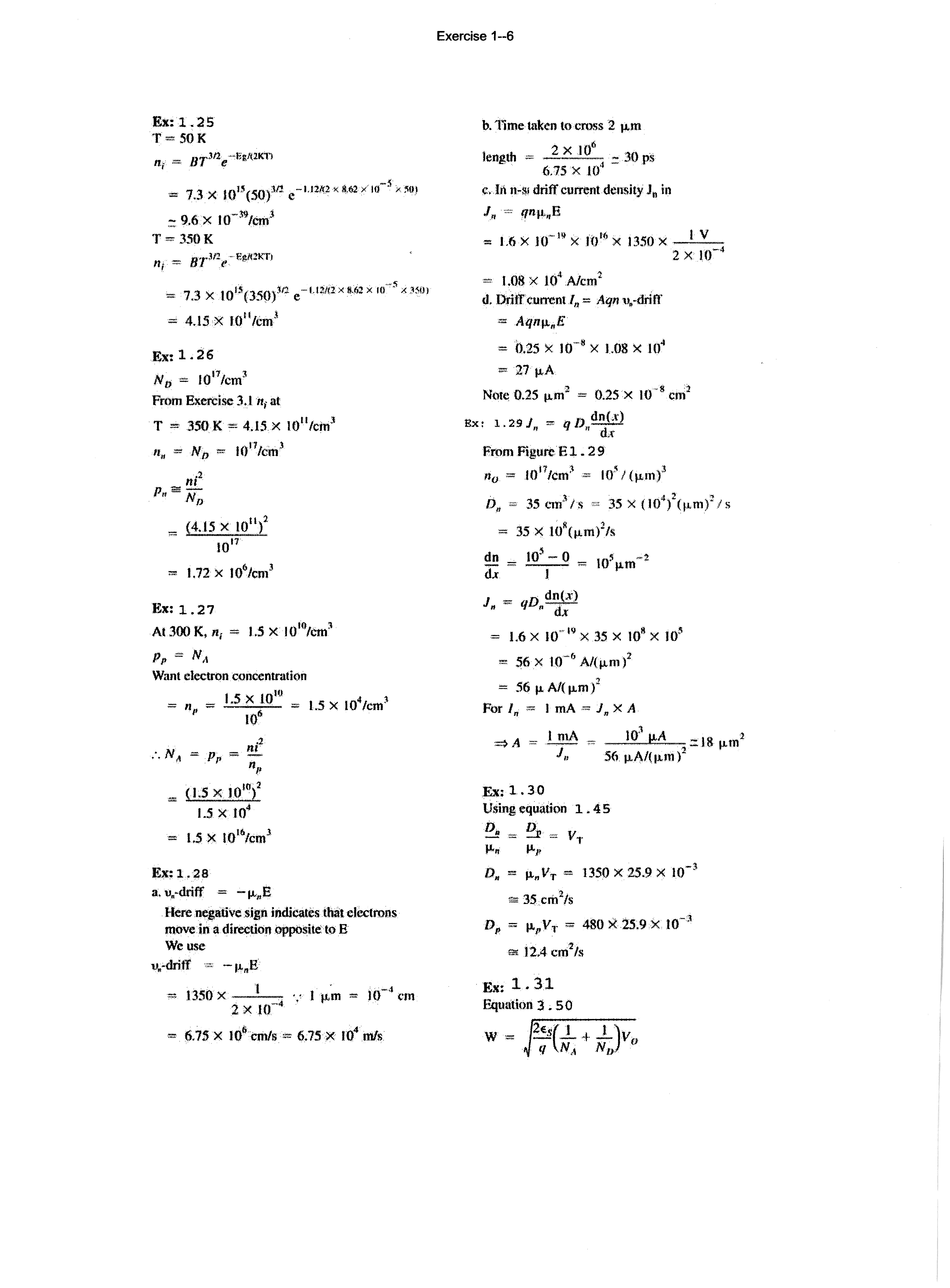
D. = v,. llo li-p
Dn = Jl,V,. = 1350X25.9X w->
$!; 35 cm 2/s -;!
Dp = )LpVT "' 480 X 25.9 X 10
a.: 12.4 cm2/s
J<;x: 1. 31
Equation 3 . 50
W=
Ex: 1.32
In a p+ n diode N 1 >> ND