Mechanics Of Materials 9th Edition Hibbeler Solutions Manual
Full Download: http://testbanktip.com/download/mechanics-of-materials-9th-edition-hibbeler-solutions-manual/
© 2014 Pearson Education,Inc.,Upper Saddle River,NJ.All rights reserved.This material is protected under all copyright laws as they currently exist.No portion of this material may be reproduced,in any form or by any means,without permission in writing from the publisher.
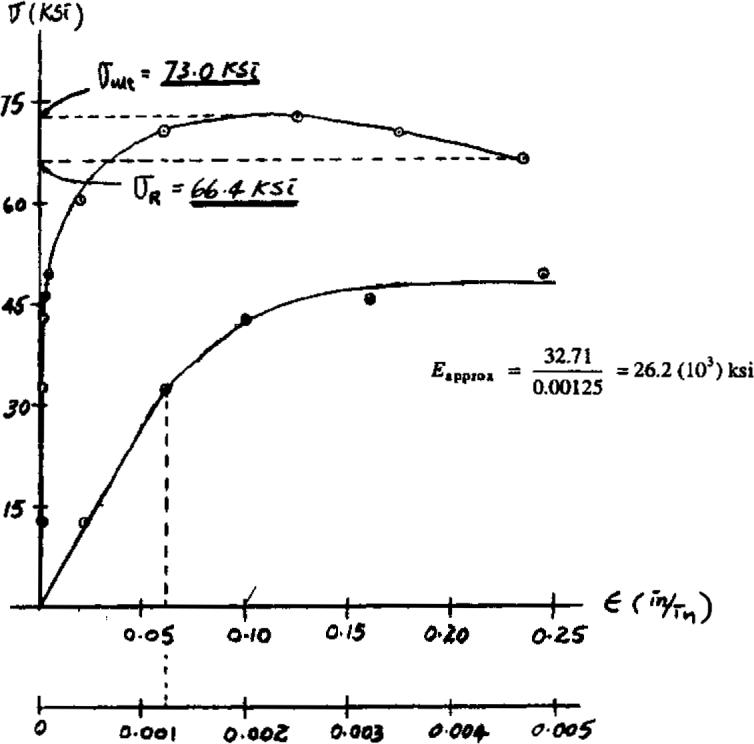
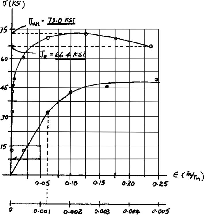
3–1. A tension test was performed on a steel specimen having an original diameter of 0.503 in.and gauge length of 2.00 in.The data is listed in the table.Plot the stress–strain diagram and determine approximately the modulus of elasticity,the yield stress,the ultimate stress,and the rupture stress.Use a scale of 1 in.20 ksi and 1 in.= 0.05 in.in.Redraw the elastic region,using the same stress scale but a strain scale of 1 in.0.001 in.in. > =
3–2. Data taken from a stress–strain test for a ceramic are given in the table.The curve is linear between the origin and the first point.Plot the diagram,and determine the modulus of elasticity and the modulus of resilience.
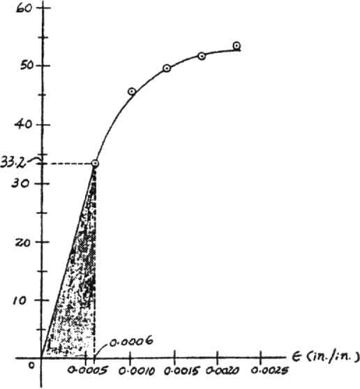
Modulus of Elasticity: From the stress–strain diagram
Ans.
Modulus of Resilience: The modulus of resilience is equal to the area under the linear portion of the stress–strain diagram (shown shaded).
Ans.
Ans:
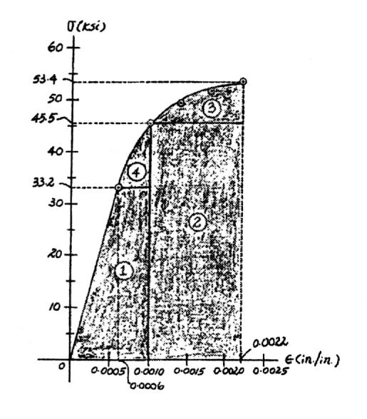
3–3. Data taken from a stress–strain test for a ceramic are given in the table.The curve is linear between the origin and the first point.Plot the diagram,and determine approximately the modulus of toughness.The rupture stress is
Modulus of Toughness: The modulus of toughness is equal to the area under the stress-strain diagram (shown shaded).
Ans:
*3–4. A tension test was performed on a steel specimen having an original diameter of 0.503 in.and a gauge length of 2.00 in.The data is listed in the table.Plot the stress–strain diagram and determine approximately the modulus of elasticity,the ultimate stress,and the rupture stress.Use a scale of 1 in.15 ksi and 1 in.0.05 in.in. Redraw the linear-elastic region,using the same stress scale but a strain scale of 1 in.0.001 in. =
3–5. A tension test was performed on a steel specimen having an original diameter of 0.503 in.and gauge length of 2.00 in.Using the data listed in the table,plot the stress–strain diagram and determine approximately the modulus of toughness.
Modulus of toughness (approx) total area under the curve
= 87 (7.5) (0.025)
= 16.3 in. # kip in3
In Eq.(1),87 is the number of squares under the curve.
3–6. A specimen is originally 1 ft long,has a diameter of 0.5 in.,and is subjected to a force of 500 lb.When the force is increased from 500 lb to 1800 lb,the specimen elongates 0.009 in.Determine the modulus of elasticity for the material if it remains linear elastic.
Ezr = 14(103) ksi, sY = 57.5 ksi.
3–7. A structural member in a nuclear reactor is made of a zirconium alloy.If an axial load of 4 kip is to be supported by the member,determine its required cross-sectional area. Use a factor of safety of 3 relative to yielding.What is the load on the member if it is 3 ft long and its elongation is 0.02 in.? The material has elastic behavior.
Allowable Normal Stress:
F.S. = sy sallow
3 = 57.5 sallow
sallow = 19.17 ksi
sallow = P A
19.17 = 4 A
A = 0.2087 in2 = 0.209 in2
Ans.
P= d L = 0.02 3 (12) = 0.000555 in.> in.
Stress–Strain Relationship: Applying Hooke’s law with Normal Force: Applying equation .
Ans:
© 2014 Pearson Education,Inc.,Upper Saddle River,NJ.All rights reserved.This material is protected under all copyright laws as they currently exist.No portion of this material may be reproduced,in any form or by any means,without permission in writing from the publisher.
*3–8. The strut is supported by a pin at C and an A-36 steel guy wire AB.If the wire has a diameter of 0.2 in.,determine how much it stretches when the distributed load acts on the strut.
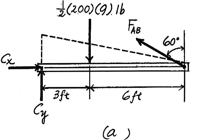
Here,we are only interested in determining the force in wire AB
+© MC = 0; FAB cos 60°(9)1 2 (200)(9)(3) = 0 FAB = 600 lb
The normal stress the wire is
sAB = FAB AAB = 600 p 4 (0.22) = 19.10(103) psi = 19.10 ksi
,Hooke’s Law can be applied to determine the strain inwire.
sAB 6 sy = 36 ksi
sAB = EPAB; 19.10 = 29.0(103)PAB
PAB = 0.6586(10 - 3) in> in
LAB = 9(12) sin 60° = 124.71 in
The unstretched length of the wire is .Thus,the wire stretches Ans. = 0.0821 in.
dAB =PAB LAB = 0.6586(10 - 3)(124.71)
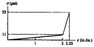
3–9. The diagram for elastic fibers that make up human skin and muscle is shown.Determine the modulus of elasticity of the fibers and estimate their modulus of toughness and modulus of resilience.
s -P
E = 11 2 = 5.5 psi
ut = 1 2 (2)(11) + 1 2 (55 + 11)(2.25 - 2) = 19.25 psi
ur = 1 2 (2)(11) = 11 psi
Ans.
Ans. Ans.
Ans:
E = 5.5 psi, ut = 19.25 psi, ur = 11 psi
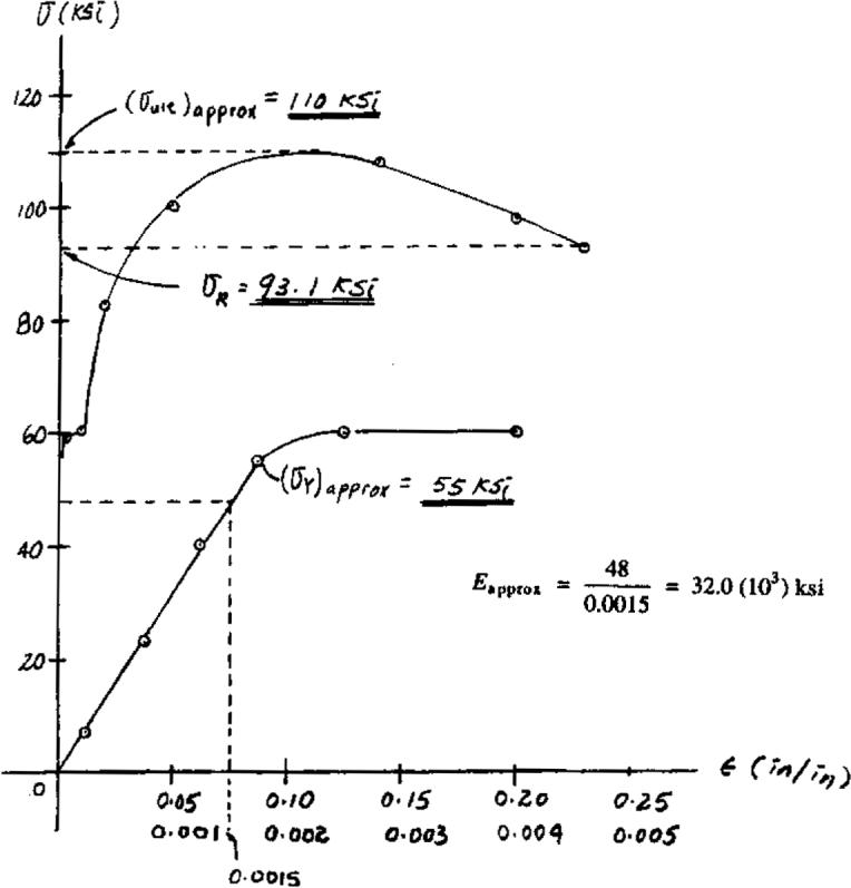
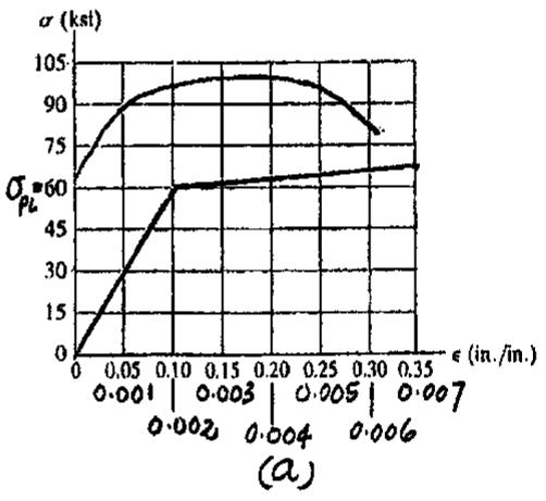
3–10. The stress–strain diagram for a metal alloy having an original diameter of 0.5 in.and a gauge length of 2 in.is given in the figure.Determine approximately the modulus of elasticity for the material,the load on the specimen that causes yielding,and the ultimate load the specimen will support.

3–11. The stress–strain diagram for a steel alloy having an original diameter of 0.5 in.and a gauge length of 2 in.is given in the figure.If the specimen is loaded until it is stressed to 90 ksi,determine the approximate amount of elastic recovery and the increase in the gauge length after it is unloaded.
From the stress–strain diagram Fig. a,the modulus of elasticity for the steel alloy is
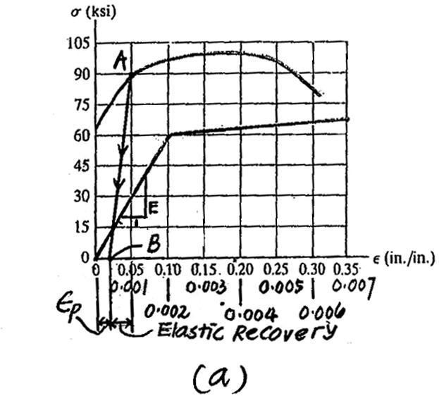
E 1 = 60 ksi - 0 0.002 - 0 ; E = 30.0(103) ksi
when the specimen is unloaded,its normal strain recovers along line AB,Fig. a, which has a slope of E.Thus
Elastic Recovery = 90 E = 90 ksi 30.0(103) ksi = 0.003 in> in.
Ans.
Thus,the permanent set is .
PP = 0.05 - 0.003 = 0.047 in> in
Then,the increase in gauge length is
Ans. ¢ L =PPL = 0.047(2) = 0.094 in.
Ans:
¢ L = 0.094 in. Elastic Recovery = 0.003 in.> in.,
*3–12. The stress–strain diagram for a steel alloy having an original diameter of 0.5 in.and a gauge length of 2 in.is given in the figure.Determine approximately the modulus of resilience and the modulus of toughness for the material.
The Modulus of resilience is equal to the area under the stress–strain diagram up to the proportional limit.
Thus,
The modulus of toughness is equal to the area under the entire stress–strain diagram.This area can be approximated by counting the number of squares.The total number is 38.Thus,
3–13. A bar having a length of 5 in.and cross-sectional area of 0.7 in.2 is subjected to an axial force of 8000 lb.If the bar stretches 0.002 in.,determine the modulus of elasticity of the material.The material has linear-elastic behavior.
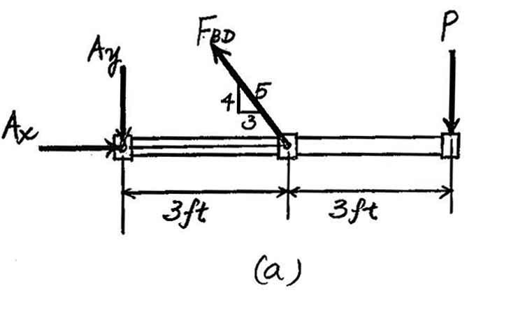
3–14. The rigid pipe is supported by a pin at A and an A-36 steel guy wire BD.If the wire has a diameter of 0.25 in.,determine how much it stretches when a load of P 600 lb acts on the pipe. =
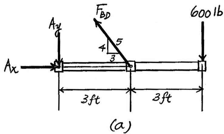
Here,we are only interested in determining the force in wire BD.Referring to the FBD in Fig. a
The normal stress developed in the wire is
Since
Law can be applied to determine the strain in the wire.
The
3–15. The rigid pipe is supported by a pin at A and an A-36 guy wire BD.If the wire has a diameter of 0.25 in., determine the load P if the end C is displaced 0.15 in. downward.
Here,we are only interested in determining the force in wire BD.Referring to the FBD in Fig. a
The unstretched length for wire BD is .From the geometry shown in Fig. b,the stretched length of wire BD is
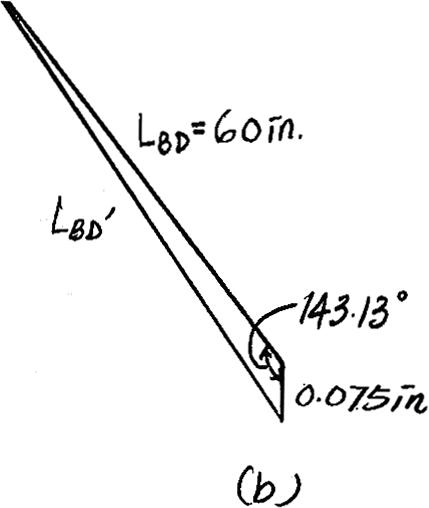
Thus,the normal strain is
Then,the normal stress can be obtain by applying Hooke’s Law. Since ,the result is valid.
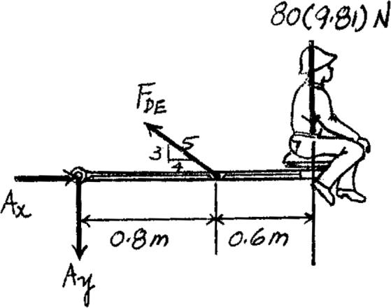
*3–16. The wire has a diameter of 5 mm and is made from A-36 steel.If a 80-kg man is sitting on seat C,determine the elongation of wire DE
600 mm 600 mm
800 mm
FDE a 3 5 b (0.8) - 80(9.81)(1.4) = 0 +© MA = 0;
FDE = 2289 N
sDE = FDE ADE = 2289 p 4 (0.0052) = 116.58 MPa
Equations of Equilibrium: The force developed in wire DE can be determined by writing the moment equation of equilibrium about A with reference to the freebody diagram shown in Fig. a, a Normal Stress and Strain: Since ,Hooke’s Law can be applied
sDE < sY
sDE = EPDE
116.58(106) = 200(109)PDE
PDE = 0.5829(10 - 3) mm> mm
The unstretched length of wire DE is Thus,the elongation of this wire is given by
LDE = 26002 + 8002 = 1000 mm.
Ans. dDE =PDELDE = 0.5829(10 - 3)(1000) = 0.583 mm
3–17. A tension test was performed on a magnesium alloy specimen having a diameter 0.5 in.and gauge length 2 in. The resulting stress–strain diagram is shown in the figure. Determine the approximate modulus of elasticity and the yield strength of the alloy using the 0.2% strain offset method.
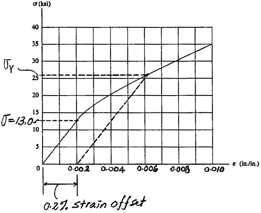
Modulus of Elasticity: From the stress–strain diagram,when ,its corresponding stress is Thus,
s = 13.0 ksi.
Eapprox = 13.0 - 0 0.002 - 0 = 6.50(103) ksi
Ans.
Yield Strength: The intersection point between the stress–strain diagram and the straight line drawn parallel to the initial straight portion of the stress–strain diagram from the offset strain of is the yield strength of the alloy.From the stress–strain diagram,
P= 0.002 in.> in.
sYS = 25.9 ksi
Ans.
Ans:
Eapprox = 6.50(103) ksi, sYS = 25.9 ksi
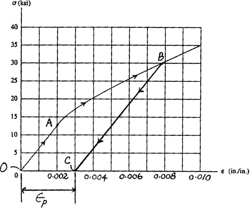
3–18. A tension test was performed on a magnesium alloy specimen having a diameter 0.5 in.and gauge length of 2 in. The resulting stress–strain diagram is shown in the figure.If the specimen is stressed to 30 ksi and unloaded,determine the permanent elongation of the specimen.
Permanent Elongation: From the stress–strain diagram,the strain recovered is alongthe straight line BC which is parallel to the straight line OA.Since then the permanent set for the specimen is
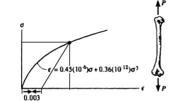
3–19. The stress–strain diagram for a bone is shown,and can be described by the equation where is in kPa.Determine the yield strength assuming a 0.3% offset.
The equation for the recovery line is
2.22(106)(P- 0.003).
This line intersects the stress–strain curve at Ans. sYS = 2027 kPa = 2.03 MPa
Mechanics Of Materials 9th Edition Hibbeler Solutions Manual Full Download: http://testbanktip.com/download/mechanics-of-materials-9th-edition-hibbeler-solutions-manual/
© 2014 Pearson Education,Inc.,Upper Saddle River,NJ.All rights reserved.This material is protected under all copyright laws as they currently exist.No portion of this material may be reproduced,in any form or by any means,without permission in writing from the publisher.
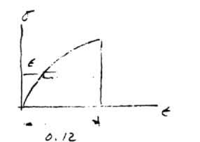
*3–20. The stress–strain diagram for a bone is shown and can be described by the equation where is in kPa.Determine the modulus of toughness and the amount of elongation of a 200-mm-long region just before it fractures if failure occurs at P= 0.12 mm> mm.