

10 Questions Every Electrical Worker Should Know How to Answer
THE MAGAZINE OF ELECTRICAL DESIGN, CONSTRUCTION AND MAINTENANCE MAY 2024 ecmweb.com IN THIS ISSUE Five Ways to Ensure a Safe Electrical Installation pg. 8 Best Practices for Online Cable Partial Discharge Testing pg. 20 Safety-Related Maintenance: The Evolving Standard pg. 44 Uncovering the Risks of Power Circuit Breaker Racking pg. 50
Why your answers could mean the difference between maintaining an electrically safe work environment and an electrical injury or fatality. Read more on pg. 36
Game-Changing Benefits. Long-Lasting Results.
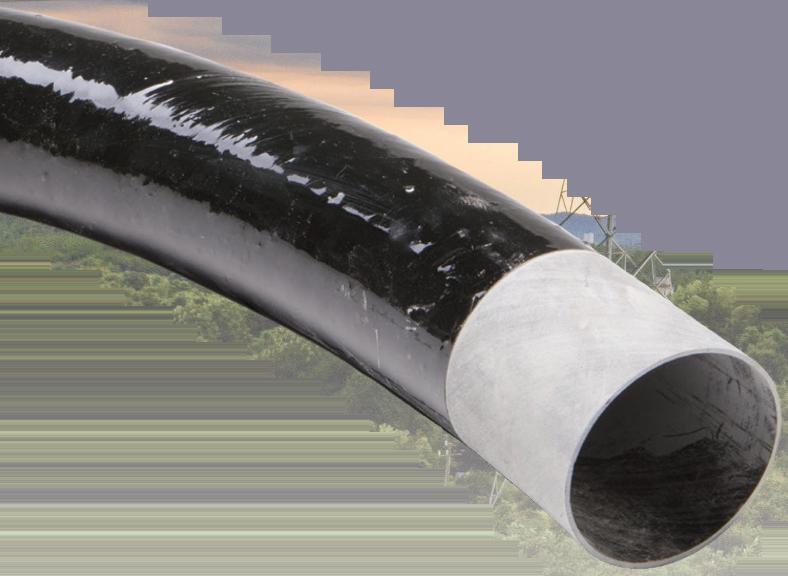
Let FRE Composites Fiberglass
Conduit Systems Be Your Solution

Bridges & Tunnels ▲ Utilities Wastewater ▲ Ports & Marine
Commercial & Industrial ▲ Data Centers
LIGHTWEIGHT
Weighs considerably less than other commonly used conduit and allows for more efficient install times
CORROSION RESISTANT
Withstands harsh environments without degrading
LOW COEFFICIENT OF FRICTION
Allows easier pull through of cables
COST EFFECTIVE
Lower cost of shipping and installation compared to other commonly used conduit
ROBUST THERMAL PERFORMANCE
Epoxy thermoset resin delivers an operating temperature of -40°F to 230°F


Scan to
more about all the benefits of FRE Composites Fiberglass Conduit Systems
learn
1/3 THE WEIGHT OF STEEL!

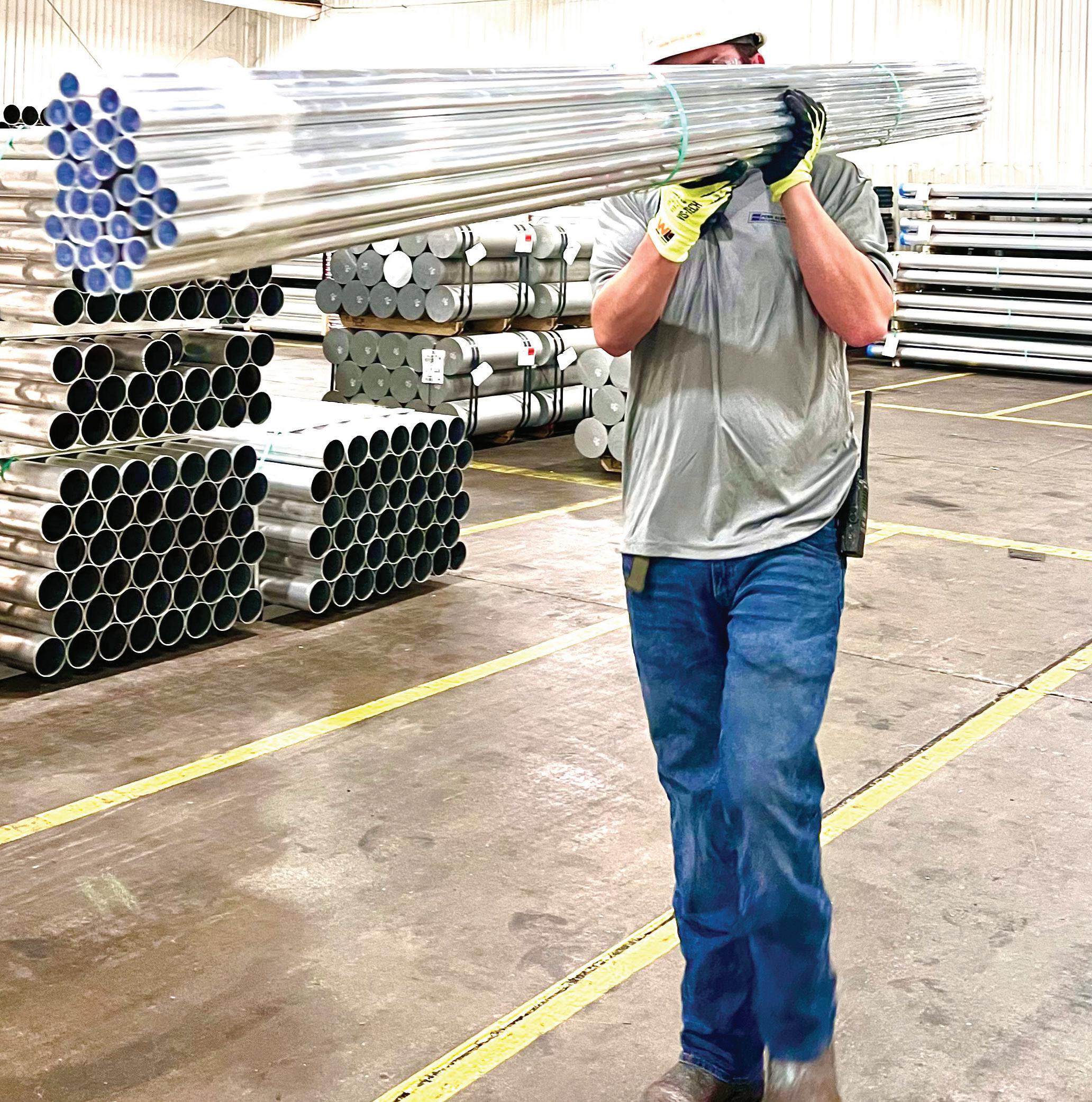
Get more done in less time with Penn Aluminum Conduit & EMT.
At 1/3 the weight of galvanized steel, Penn Aluminum Conduit and EMT are easier to lift and carry, often requiring just one person when two or more would be needed with steel. That makes installation – including onsite fabrication, such as cutting, bending and threading – faster and easier. So projects are completed in less time. Plus, you get all these additional benefits:
• Safer to lift and carry
• Produced using recycled aluminum
• 100% recyclable
• Non-corrosive and non-sparking
• EMT is available with our proprietary, UL-listed Blue Lightning® wire pulling compound
That’s why Penn Aluminum Conduit & EMT is The Smart Choice for electrical contractors.

MADE IN AMERICA For additional information and resources visit: pennconduit.com
Now that NFPA

Lack of formal training reveals gaps in competency among electrical professionals when working on new electrical power distribution equipment, especially racking out or in low- or high-voltage power circuit breakers.
approach to verifying the absence of
online cable partial discharge testing
on
construction job sites


CONTENTS 2 May 2024 • www.ecmweb.com COVER STORY 36 10 Questions Every Electrical Worker Should Know How to Answer Why your answers could mean the difference between maintaining an electrically safe work environment and an electrical injury or fatality OTHER FEATURES 44 Safety-Related Maintenance: The Evolving Standard
70B
elevated to a standard, it’s critical to understand
electrical standards should work together. 50 Uncovering the Risks of Power Circuit Breaker Racking
has been
how all of the
NATIONAL ELECTRICAL CODE 57 Code Basics NEC requirements for services — part 2 60 Code Quiz of the Month Test your Code IQ 62 Illustrated Catastrophes More Code catastrophes 64 What’s Wrong Here? Can you spot the Code violations? DEPARTMENTS 6 Industry Viewpoint 8 Safety Corner Five ways
safe electrical installation 12 Eye on Safety A safer
voltage 20 Electrical Testing Education Understanding
30 Job-Site Intelligence Identifying patterns
electrical
55 New Product Showcase Focus on safety equipment, workwear, and PPE 56 Product News May 2024 • Volume 123 • Number 5 12 20 30 60 62 36 Cover: Photo 18915280 | © Jaypetersen | Dreamstime.com
to ensure a
ECMWEB.COM
With its exclusive online content, ecmweb.com is a valuable source of industry insight for electrical professionals. Here’s a sample of what you can find on our site right now:
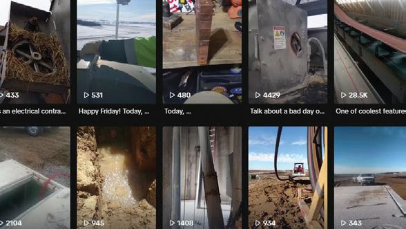
THE TOP EVERYDAY ELECTRICIAN VIDEOS OF APRIL 2024
Video See the three most popular The Everyday Electrician videos from Trevor Ottmann, president of 3/0 Electric. ecmweb.com/55038439

MONTHLY QUIZ: SWIMMING POOL REQUIREMENTS AND THE NEC
Quiz Take this quiz about NEC requirements for swimming pools, and enter for a chance to win a $25 gift card to Amazon! ecmweb.com/55020056

HOW TO PERFORM ELECTRICAL MAINTENCE MORE EFFICIENTLY
Safety Electrical Consultant Mark Lamendola shares four electrical maintenance hacks to keep in mind. ecmweb.com/55037598
Editorial
Group Editorial Director - Buildings & Construction: Michael Eby, meby@endeavorb2b.com
Editor-in-Chief: Ellen Parson, eparson@endeavorb2b.com
Managing Editor: Ellie Coggins, ecoggins@endeavorb2b.com
Editor: Michael Morris, mmorris@endeavorb2b.com
Art Director: David Eckhart, deckhart@endeavorb2b.com
Consultants and Contributors
NEC Consultant: Mike Holt, mike@mikeholt.com
NEC Consultant: Russ LeBlanc, russ@russleblanc.net
Sales and Marketing
VP/Market Leader - Buildings & Construction: Mike Hellmann, mhellmann@endeavorb2b.com
Regional/Territory Account Manager: David Sevin, dsevin@endeavorb2b.com
Regional/Territory Account Manager: Jay Thompson, jthompson@endeavorb2b.com
Media Account Executive – Classifieds/Inside Sales: Steve Suarez, ssuarez@endeavorb2b.com
Production and Circulation
Production Manager: Brenda Wiley, bwiley@endeavorb2b.com
Ad Services Manager: Deanna O’Byrne, dobyrne@endeavorb2b.com
User Marketing Manager: James Marinaccio, jmarinaccio@endeavorb2b.com
Classified Ad Coordinator: Terry Gann, tgann@endeavorb2b.com
Endeavor Business Media, LLC
CEO: Chris Ferrell
CRO: Paul Andrews
President: June Griffin COO: Patrick Rains
Chief Digital Officer: Jacquie Niemiec
Chief Administrative and Legal Officer: Tracy Kane
EVP, Group Publisher – Buildings/Lighting/Digital Infrastructure: Tracy Smith
Electrical Construction & Maintenance (USPS Permit 499-790 , ISSN 1082-295X print, ISSN 2771-6384 online) is published monthly by Endeavor Business Media, LLC. 201 N. Main St 5th Floor, Fort Atkinson, WI 53538. Periodicals postage paid at Fort Atkinson, WI, and additional mailing offices. POSTMASTER: Send address changes to Electrical Construction & Maintenance, PO Box 3257, Northbrook, IL 60065-3257. SUBSCRIPTIONS: Publisher reserves the right to reject non-qualified subscriptions. Subscription prices: U.S. ($68.75 year); Canada/Mexico ($ 112.50); All other countries ($162.50). All subscriptions are payable in U.S. funds. Send subscription inquiries to Electrical Construction & Maintenance, PO Box 3257, Northbrook, IL 60065-3257. Customer service can be reached toll-free at 877-382-9187 or at electricalconstmaint@omeda.com for magazine subscription assistance or questions.
Printed in the USA. Copyright 2024 Endeavor Business Media, LLC. All rights reserved. No part of this publication may be reproduced or transmitted in any form or by any means, electronic or mechanical, including photocopies, recordings, or any information storage or retrieval system without permission from the publisher. Endeavor Business Media, LLC does not assume and hereby disclaims any liability to any person or company for any loss or damage caused by errors or omissions in the material herein, regardless of whether such errors result from negligence, accident, or any other cause whatsoever. The views and opinions in the articles herein are not to be taken as official expressions of the publishers, unless so stated. The publishers do not warrant either expressly or by implication, the factual accuracy of the articles herein, nor do they so warrant any views or opinions by the authors of said articles.
Reprints: Contact reprints@endeavorb2b.com to purchase custom reprints or e-prints of articles appearing in this publication.
Photocopies: Authorization to photocopy articles for internal corporate, personal, or instructional use may be obtained from the Copyright Clearance Center (CCC) at (978) 750-8400. Obtain further information at www.copyright.com.
Archives and Microform: This magazine is available for research and retrieval of selected archived articles from leading electronic databases and online search services, including Factiva, LexisNexis, and ProQuest.
Privacy Policy: Your privacy is a priority to us. For a detailed policy statement about privacy and information dissemination practices related to Endeavor Business Media products, please visit our website at www.endeavorbusinessmedia.com.
Please Note: The designations “National Electrical Code,” “NE Code,” and “NEC” refer to the National Electrical Code®, which is a registered trademark of the National Fire Protection Association.
Corporate Office: Endeavor Business Media,
4 May 2024 • www.ecmweb.com May 2024, Vol. 123/No. 5 www.ecmweb.com
LLC, 30 Burton Hills Blvd., Ste 185, Nashville, TN 37215 USA, www.endeavorbusinessmedia.com
130445275 © Tashatuvango Dreamstime.com 22338935 © Elena Elisseeva | Dreamstime.com

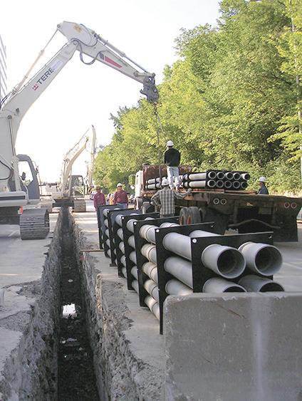
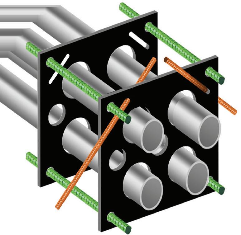
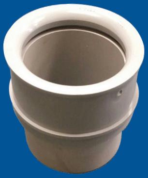

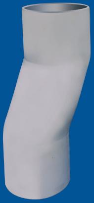
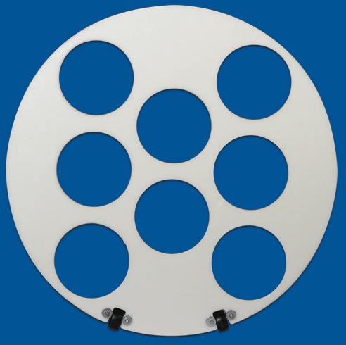


SPProducts.com 800-233-8595 info@SPProducts.com Plus More Being Invented for SAFER BETTER FASTER Jobs . . . Call With Your Ideas! Patent Pending Patent Pending Bore Spacers Sizes 1/2” thru 6” Roll assembled conduit into caissons and under obstructions PVC Offset Sizes 1/2” thru 6” Meets Flexible Mandrel Test Requirements
Deaths.
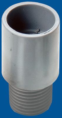
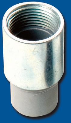
Save on Installation! IP3b IP2 We’re Proud to be the Electricians’ Friend for Over 50 Years! FOR SAFER BETTER FASTER JOBS MADE IN USA HDPE CUSTOM TEMPLATES In Any Configuration Required Qwik Duct Safer Better Faster IP1 Save Cost on the Rigid Nipple, Tape & Labor Use for Entire Job - Not Just for Repair PVC/Rigid PVC/PVC PVC/EMT PVC/Flex NEW PVC/Alum NEW PVC/Stainless C/St i l NEW PVC/Liquidtite NEW IP13A-F Conduit Transition Couplings PVC Schedule 40 & 80 Transitions in Less Than 5 Minutes PATENT PENDING PATENT PENDING C US C US C US C US 1 Piece Reaming Bit 1/2” thru 6” Schedule 40/80 PATENT PENDING IP15 IP15 End Bell Adapter Schedule 40/80 PVC ER B ER AF ETT D S MA E
Assemble Conduit Above TrenchNo Workers BelowPrevents Injuries and
Also Allows Digging a Narrower Trench for Less: Excavation, Concrete, Slurry, Backfill & Shoring.
Electrical Accident Analysis Sheds Light on Industry Stats
By Ellen Parson, Editor-in-Chief
As we do every May, we are dedicating the majority of editorial content to health and safety topics in this issue. Starting with Construction Safety Week, which was observed May 6-10 this year, many of our readers engage in their own safety events to increase awareness and commemorate this important week. But, as we all know, electrical safety isn’t something you focus on once a year, once a month, once a week, or even once a day. Among electrical professionals, it’s something that demands a lifelong commitment of awareness, education, and action.
Every year, the Electrical Safety Foundation (ESFI) collects and publishes workplace electrical injury data covering incidents from the previous year — the most recent data of which covers 2011 to 2022. Visit ESFI’s website at esfi.org to access free resources that will help elevate the safety of job sites as well as prevent avoidable workplace injuries and fatalities. According to a recent press release summarizing the latest ESFI analysis of this data, contact with or exposure to electricity “continues to be one of the leading causes of workplace fatalities and injuries in the United States.” In fact, during that 11-year time period, 1,322 workplace fatalities involved electricity, according to OSHA. Following are a few more significant statistics to note:
• Seventy percent of workplace electrical fatalities occurred in non-electrical occupations.
• Thirty percent of workplace electrical fatalities occurred in electrical occupations.
• Six percent of all fatalities were caused by contact with electricity.
• There was a 1.5% average decrease in workplace electrical fatalities year over year.
• The construction industry had the highest number of electrical fatalities (electricians accounted for 195 deaths, making it the occupation with the greatest number of fatalities).
Digging into these stats a bit further, based on information from OSHA as well as the U.S. Bureau of Labor Statistics (BLS) Census of Fatal Occupational Injuries (CFOI) and Survey of Occupational Injuries (SOII), ESFI’s analysis revealed some additional key points: electrical fatality rates per 100,000 workers have remained consistent while overall fatality rates have increased; Hispanic or Latino workers have the highest rate of electrical fatalities (and that rate continues to rise); and construction/ extraction occupations, installation, maintenance, and repair occupations, and building/grounds cleaning and maintenance occupations have the highest rate of electrical fatalities.
Why do the same types of accidents continue to occur in the construction and electrical industries — with fall protection serving as a perfect example? For the 13th year in a row, “Fall Protection — General Requirements” secured the No. 1 spot on OSHA’s Top 10 most frequently cited safety standards for 2023. Presented by OSHA’s Region 6 Administrator Eric Harbin during the 2023 National Safety Council (NSC) Safety Congress & Expo, which took place from Oct. 20-26, 2023, the list remains relatively unchanged from previous years. Visit our gallery at ecmweb.com/55017827 to see the full list of violations along with more details. Although individual categories tend to swap positions from year to year, the same usual suspects show up again and again. What troubles me most after looking through this year’s list is the fact that none of the top 10 categories saw a decrease in the total number of incidents from the previous year’s totals.
To put this frustrating trend into perspective, I can’t help but think back to some of Randy Barnett’s words of wisdom, of which there are too many to count in my experience. An NFPA-certified electrical safety professional, journeyman electrician, electrical trainer/instructor, Electrical Codes & Safety Manager for NTT Training, and longtime contributor to EC&M, Randy always warns electrical professionals must never underestimate the “human factor” involved with performing any type of electrical work. Therefore, taking preemptive action before a burn, injury, or fatality can occur is invaluable. That’s where every one of you comes in — by keeping electrical safety top of mind every second of every day while on the job, we can strive to drastically reduce the number of workplace accidents one electrical task at a time.

INDUSTRY VIEWPOINT 6 May 2024 • www.ecmweb.com


As a small business owner, you can’t escape your to-do list. That’s why Progressive makes it easy to save with a commercial auto quote, so you can take on all your other to-dos. Get a quote in as little as 7 minutes at ProgressiveCommercial.com P r o g r e s s i v e C a s u a l t y I n s C o C o v e r a g e p r o v d e d a n d s e r v c e d b y a f fi l i a t e d a n d t h i r dp a r t y i n s u r e r s
Five Ways to Ensure a Safe Electrical Installation
Learn how to leverage an ecosystem of fire and life safety resources.
By Corey Hannahs, NFPAAfter spending all my professional career in the electrical industry, 25 of which were in the electrical contracting side of the business, I have seen the good, the bad, and the ugly side of electrical installations. To be fair, I don’t believe that anyone ever intentionally sets out to perform a bad installation that is unsafe for the end-user, yet we see them regularly. Maybe there is a knowledge gap on how things should be done correctly or immense pressure to rush through a job based on workload demands. Whatever the reason, there seems to be a disconnect in many cases for performing a safe electrical installation.
Another thing that I have seen over the years in the electrical industry is an immense sense of pride in the trade. Electricians and electrical contractors are extremely prideful of the work they perform and the mark that it leaves in their communities. Without question, they want to leave a positive impact on the place that they call home.
When we start thinking about the role the electrical industry plays in the overall safety of the world, it is significant. The installations we provide can make a difference in the safety of a curious child if power is functioning for a critical, lifesaving surgery, or whether a home catches on fire or it doesn’t. What we do matters in the world. Working within the electrical industry, it is easy to have our blinders on and see only the immediate impact of our work, but there is so much more at stake.
Enter the NFPA Fire & Life Safety Ecosystem™. This ecosystem is a framework that identifies the components that must work together to minimize
risk and help prevent loss, injuries, and death from fire, electrical, and other hazards. There are eight key components to the ecosystem:
• Government responsibility.
• Development and use of current codes.
• Referenced standards.
• Investment in safety.
• Skilled workforce.
• Code compliance.
• Preparedness and emergency response.
• Informed public.
It is important to understand that these components are interdependent. When they work together, the ecosystem protects everyone. If any component is missing or broken, the ecosystem can
collapse, often resulting in tragedy. We can almost always trace the cause of injurious life safety incidents and tragedies back to the breakdown of one or more components. While the electrical industry does not have a direct impact on every component within the ecosystem, there are five that stand out; incorporating them into the work that we do will help to ensure safe electrical installations are being performed.
1. DEVELOPMENT AND USE OF CURRENT CODES
This is a two-part component consisting of both the development and use of current codes. Let’s talk development to start. All NFPA codes and standards are created and updated each cycle through
8 May 2024 • www.ecmweb.com SAFETY
CORNER
300386306 © Mohamed Ahmed Soliman | Dreamstime.com
Photo
a full, open, consensus-based standards development process. It is important to know that there are roles for everyone in this process. All codes and standards have at least one — and many times multiple — committees of volunteers that oversee their development. For example, the National Electrical Code (NEC) has a significant number of Code-Making Panels (CMPs) that review the proposed changes each cycle. The 2026 NEC cycle that is being worked on right now has 18 CMPs. Electricians and electrical contractors are able and encouraged to apply to be on a CMP by visiting the NEC document information page and selecting the “Technical Committee” tab. You also have the opportunity to propose changes to the NEC by submitting a public input or public comment when the associated stage of the standards development process is open.
The other part of the current codes component is simply using them. Being on a three-year cycle allows the NEC to
be updated to reflect the latest in safe installation requirements and technological advancements. Areas such as energy storage systems (ESSs), photovoltaic (PV) installations, and electric vehicles (EVs) all impact current electrical installations, making it crucial to utilize the most up-to-date code requirements to help ensure safety.
What may come as a surprise is that many states and jurisdictions fall short of enforcing the most current NEC by several editions. For example, some states still reference the 2008 NEC. It likely needs no explanation as to how much technology has advanced and safety needs have changed from 15-year-old Code cycles until now. While implementation of the most current codes and standards in communities often gets caught up in the legislative process, it is important to know that as electricians and electrical contractors (and as citizens) you have a voice in that process. Find time to explain to your local legislators why using the most
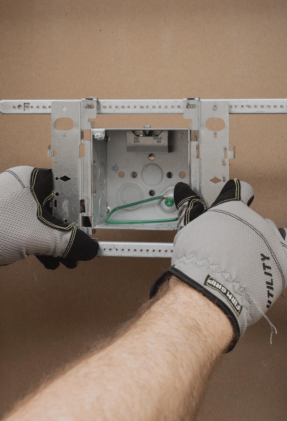
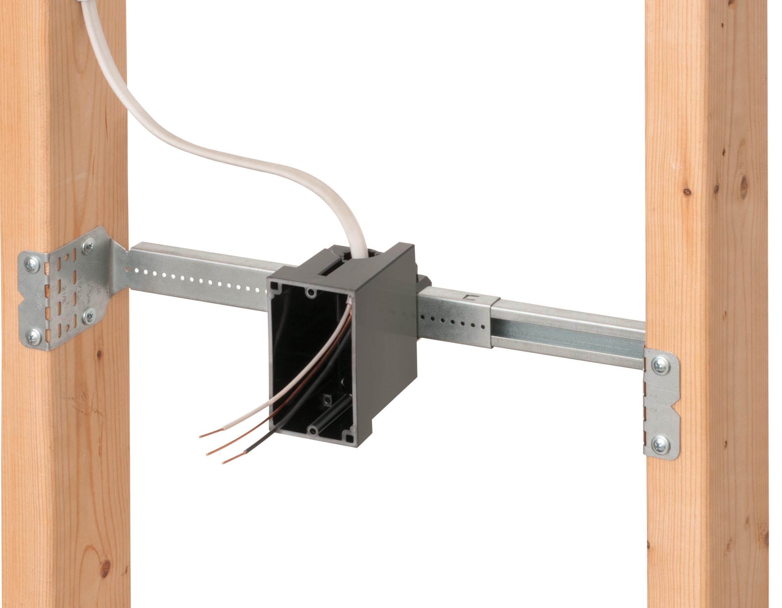
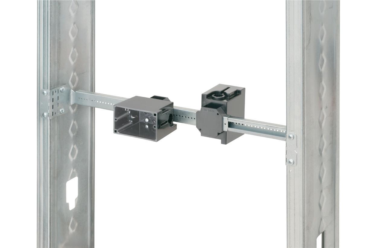
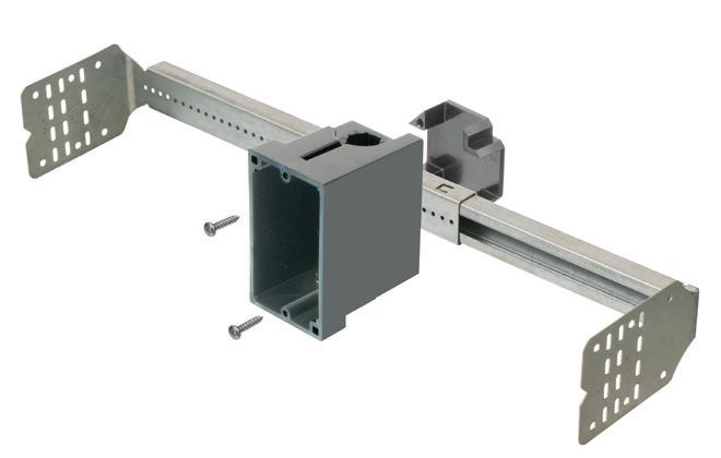
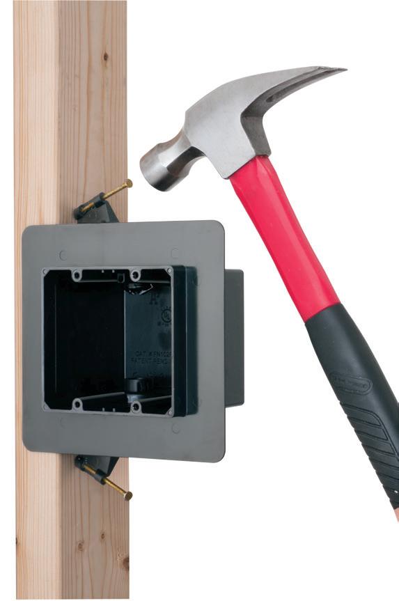
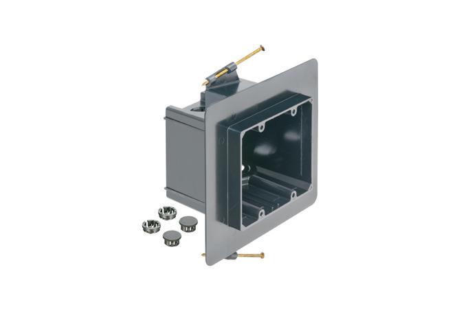
Ultimate G series brackets
Efficient brackets make prefab easy!
Easily mount any box and mud ring to studs or our new open center bracket! Ultimate G series brackets maximize flexibility, saving time and labor. The gangable design that lets you simply add boxes on either side, reducing SKUs. Plus, it holds the box for hands-free installation.
Perfect for prefab—RACO’s ProReady™ solutions drive installation simplicity and efficiency! Ultimate G series brackets are available individually or with built-in STAB-iT® boxes or Hinged Adjustable Mud Rings.
current codes and standards is critical to the safety of your community.
2. INVESTMENT IN SAFETY
As an electrical contractor, it’s clear that our people are our most valuable asset. Without them, the work that we do can’t be done. The safety of employees needs to be paramount in a business. There is not only a legal responsibility from an OSHA standpoint but also an ethical responsibility to ensure that all employees go home at night the same way they came to work. The safety of employees simply can’t happen without an investment. Employees need to be trained regularly for safety in the specific tasks they perform. That goes for electrical-related tasks or other items such as operating a scissor lift or utilizing powder-actuated equipment. Employees should be trained to identify and manage any risks they face while performing their jobs. Treat them as the most important asset to the business because they are.
Try RACO G brackets for yourself! Scan to request a sample.
www.ecmweb.com • May 2024 9
NEW!
2405ECM_Hubbell_Gseries.indd 1 4/11/24 4:00 PM
SAFETY CORNER
3. SKILLED WORKFORCE
Technical training is also key to developing a skilled workforce. This is in the best interest of the community because safe installations can only be performed by those who are skilled in what they do. It is also crucial to the business’s bottom line. Workers skilled in what they do can perform the work expediently and accurately, both of which are huge benefits to the business from a competitive advantage and potential profit standpoint. Rework and reinspection fees can cost a business a significant amount of money. With thin profit margins, these costs can turn a project from a money-maker to a loss in the blink of an eye. There is no doubt that training employees has a large cost associated with it, but it can be argued that not training your employees has an even greater cost.
4. CODE COMPLIANCE
Code compliance goes hand-inhand with using the most current codes. Utilizing the most current codes for installations is the best way to ensure it is safe, but there is also a need to verify that those requirements have indeed been met. That is where the authority having jurisdiction (AHJ) comes into play. The AHJ is the last line of defense between a safe electrical system for the end-user and an unsafe one. They need to be fully involved in the installation and closeout process. Pull the permit, get the proper job progress inspections (e.g., underground, rough wall, etc.), and then, the final inspection. Work that gets done without proper permits happens way too often and not only puts the electrical system owner and building occupants at risk, but it also puts the electrical contractor and electricians at risk of litigation, should something go wrong. Ensuring code compliance is a key part of safety for all involved.
5. INFORMED PUBLIC
Post-installation considerations are just as important as the initial installation. Help others to understand the dangers of electricity. Often you may hear of individuals choosing to perform their own electrical work at their home or business. They may even reach out to you for advice on how to do something. They must know that it isn’t work they should be doing. Just like an electrician wouldn’t
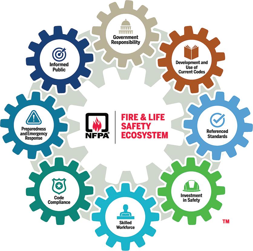
The eight components of the NFPA Fire & Life Safety Ecosystem work together to minimize risks and prevent injury, loss, and death.
attempt to do open heart surgery, which could negatively impact the life of one person, those who are not trained to do electrical work should not attempt something that can impact the lives of many. It is also important at the end of an installation to make sure that the homeowner or business owner is aware of how their electrical system and its components work, specifically noting what needs to be maintained. It may even be a good time to offer a service contract where you can offer continual service. The key point is don’t just perform the installation and walk away. Be sure to take the time to talk with customers and answer any questions they may have to ensure they fully understand their electrical system including maintenance needs, and other ways to stay safe.
CONCLUSION
Those who work in the electrical industry play a monumental role in safety all over the world. Being responsible for installing and maintaining electrical systems that
others depend on for functionality and safety is a role that should not be taken lightly. Remember, if one component fails, they all fail. Whether it is lighting up a dark room or powering up a manufacturing machine, success in the electrical industry is achieved by making things work safely. Knowing how important our role of safety is in the cohesive world around us, I encourage everyone to begin implementing the five components of the Ecosystem discussed in this article in all your future installations.
Important notice: Any opinion expressed in this column is the opinion of the author and does not necessarily represent the official position of NFPA or its Technical Committees. In addition, this piece is neither intended nor should it be relied upon to provide professional consultation or services.
Corey Hannahs is a senior electrical content specialist at the National Fire Protection Association (NFPA). He can be reached at channahs@nfpa.org
10 May 2024 • www.ecmweb.com

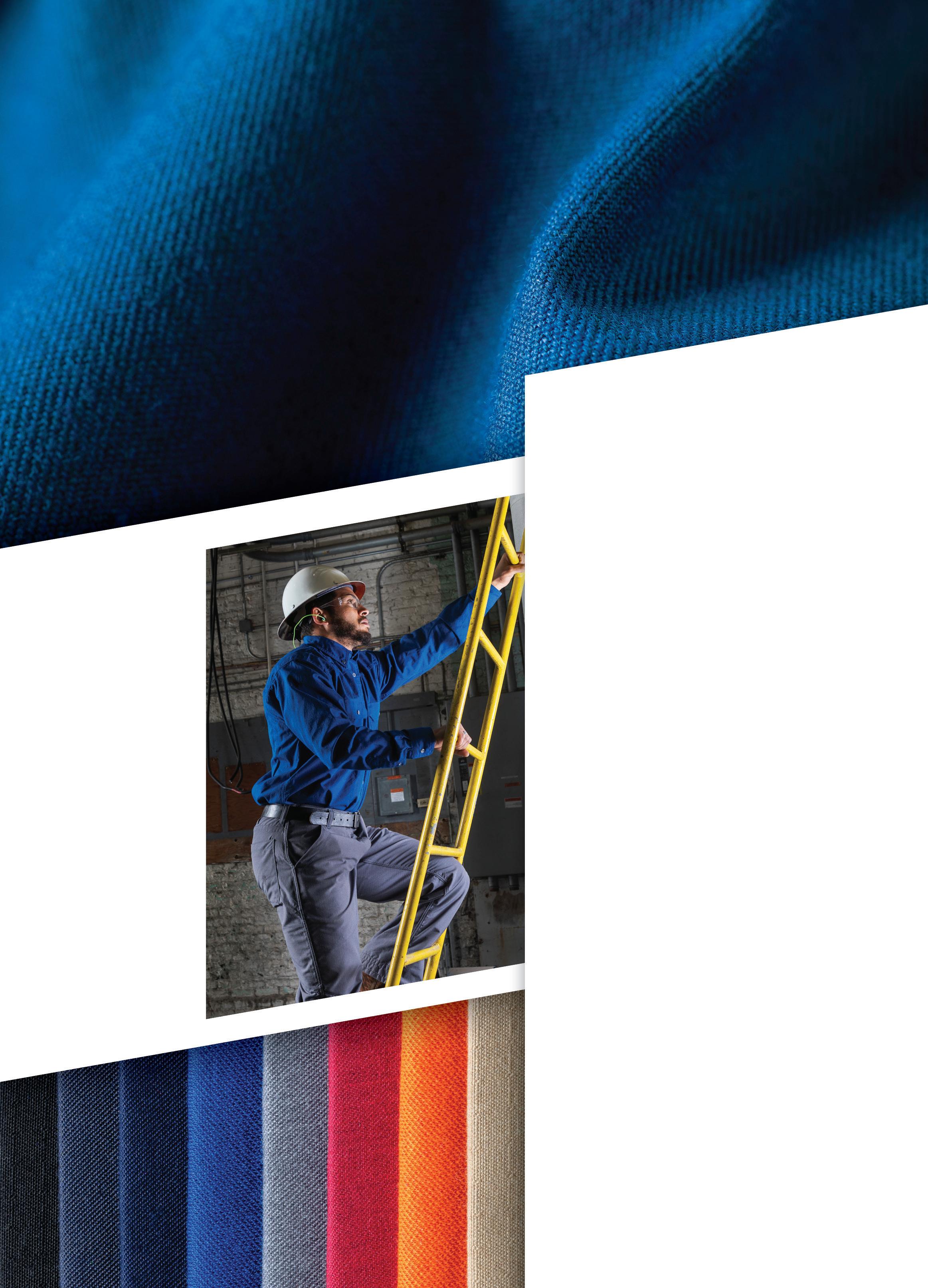
ADVANCED AR/FR FABRICS FOR WORKWEAR
PERFORMANCE DURABILITY
COMFORT
SAFETY MADE SIMPLE
In the field it’s known as “cheating” compliance – workers rolling up their sleeves, loosening buttons, or wearing non-compliant workwear altogether.
But worker safety is not a game, and there are no shortcuts. So, if PPE compliance falls on your plate, choose garments made with GlenGuard – the most comfortable, durable, and versatile AR/FR fabric in the workwear world.
With the industry’s best weight-toprotection ratio, GlenGuard helps workers reach their peak performance and stay in compliance. Comfortable workers lead to a compliant workforce.
+
TEAM IMAGE
TO LEARN
VISIT GLENGUARD.COM
SCAN
MORE OR
+
EYE ON SAFETY
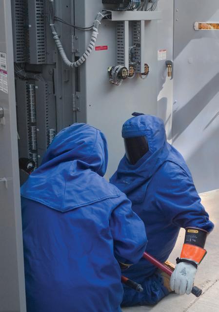
A Safer Approach to Verifying the Absence of Voltage
Best practices for preventing electrical-related injuries and fatalities due to working on or near live equipment
By Sudhir Pandey, I-Gard Corporation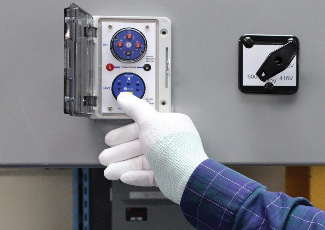
Ensuring the safety of employees in the workplace is undeniably the foremost responsibility of any company. While the importance of workplace safety is universally acknowledged, a disconcerting question arises: Why do incident rates of electrical injuries — and, in some tragic cases, fatalities — persist without showing a significant decline year over year despite the purported priority placed on employee safety?
WORKPLACE ELECTRICAL INJURIES AND FATALITIES
Most electrical accidents occur because people are working on or near equipment that is:
• Thought to be dead but is live.
• Known to be live, but those involved do not have adequate training/ appropriate equipment or have not taken adequate precautions.
A recent report by the Electrical Safety Foundation International (ESFI) covering workplace accidents from 2011 to 2022 raises concerns. The data, depicted in Fig. 1 on page 14, shows that approximately 48% of reported fatalities occurred while working with or near live electrical parts, highlighting the increased vulnerability associated with working near live conductors.
Despite advancements in safety protocols, ESFI’s findings in Fig. 2 on page 14 and Fig. 3 on page 16 reveal there
hasn’t been a significant decrease in fatalities and injuries related to electrical incidents over the years. Additionally, it’s noteworthy that these accidents aren’t limited to inexperienced workers. Data in Fig. 4 on page 16 from the Survey of Occupational Injury and Illness (SOII) on nonfatal work injuries caused by exposure to electricity by workers years of service indicates that most nonfatal electrical injuries involve workers with over a year of experience with their employer.
These findings emphasize that even experienced personnel are susceptible to accidents, suggesting that human error remains a significant factor contributing to such incidents.
USE OF VARIOUS INSTRUMENTS FOR VERIFYING THE ABSENCE OF VOLTAGE
Both NFPA 70E, Standard for Electrical Safety in the Workplace, and CSA Z462, Workplace Electrical Safety, have undergone significant changes over the past few years, allowing for the acceptance of various instruments for verifying the absence of voltage.
MULTIMETERS
The 2015 edition of NFPA 70E stressed the importance of a safer work environment by recommending the use of an adequately rated test instrument, which is often interpreted as a multimeter, to directly test phase conductors or circuit paths. This method involves opening electrical cabinets, wearing proper safety gear, and making direct contact with equipment. This approach of direct testing

12 May 2024 • www.ecmweb.com
NO BURN-THROUGH
CHAMPION DUCT® SOLVES
UTILITIES CHALLENGES
No burn-through eliminates elbow repairs
Lower material and installation costs

DOWNLOAD FIBERGLASS VS
GRC
COMPARISON
Fault resistance makes repairing cables easy
Durable and corrosion-resistant for project longevity
©2016 Champion Fiberglass, Inc. BIM/REVIT
Champion Fiberglass® Elbows
EYE ON SAFETY
poses challenges due to potential human errors, including the risk of unintentional contact with live conductors or the incorrect selection of inadequately rated test equipment.
Data from Fig. 2 and Fig. 3 illustrate that from 2015 to 2017 there was no significant reduction in fatal and nonfatal injuries. Recognizing these challenges opened up opportunities for exploring alternative methods and technologies to enhance electrical safety in the workplace.
VOLTAGE TEST PORTS
In 2018, the NFPA 70E standard saw an update in Sec. 120.5, introducing an exception (Exception No. 1 to Rule 7). This exception allowed the use of a properly rated permanently mounted electrical test device to verify the absence of voltage. This led to the widespread adoption of voltage indicators and test ports for this crucial test. The rationale behind this approach was simple: Conducting the test with the door closed reduced the risk of unintentional contact with current-carrying conductors. The expectation was that the industry would see a significant decrease in fatal and non-fatal incidents.
However, despite the increased use of voltage indicators and test ports, there hasn’t been a significant decrease in incident rates. Figure 2 and Fig. 3 show there’s been no major decline in fatalities and/or injuries from 2018 onwards. This raises the question of why this is the case. Here are two potential answers.
1. Seeing 0V at the end of a test port doesn’t ensure that there’s no voltage on the current-carrying conductors. There are situations (such as when wires are missing or loose or if a fuse between the test port and the current-carrying conductors is blown) where the meter may show 0V even if there’s still voltage.
2. Voltage test port results may not be fully trusted by qualified workers, potentially prompting them to open the door of the electrical cabinet for a physical inspection. This action exposes workers to the risk of unintentional contact with live conductors, thereby defeating the purpose of conducting the test with the door closed.
It’s worth mentioning that in the 2024 edition of NFPA 70E, ANNEX O.2.4 includes the use of voltage test ports as an additional Safety-by-Design method. These voltage test ports are recognized as effective design features for minimizing risks related to arc flash or electric shock hazards. By enabling voltage measurement and troubleshooting without the need to physically open the door, they significantly reduce exposure to potential hazards.
ABSENCE OF VOLTAGE TESTER
An absence of voltage tester (AVT) is designed to confirm the absence
41% Contact with overhead power lines
6% Lockout/tagout safety devices removed
3% PPE issue
1% Arc flash/blast
48% Working on or near energized wires or parts
Source: ESFI
of electrical voltage without the need to physically open equipment doors, thus minimizing the risk of exposure to electrical hazards. Its significance has been acknowledged by NFPA 70E 2021, which updated Rule 7 of Section 120.5, replacing the term “permanently mounted test device” with “permanently mounted absence of voltage tester” for clearer safety guidelines. Additionally, it mandated that AVTs adhere to the standards set by UL 1436.
The evolution continues with the NFPA 70E 2024 update in Rule 7 of Section 120.6, emphasizing the necessity
14 May 2024 • www.ecmweb.com
Fig. 1. Forty-eight percent of reported fatalities occurred while working with or near live electrical parts.
Year 200 180 160 140 120 100 80 60 40 20 0 Number of Fatal Injuries 2011 2012 2013 2014 2015 2016 2017 2018 2019 2020 2021
Fig. 2. The number of electrical-related fatalities has remained fairly consistent over this time frame.
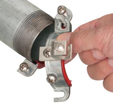
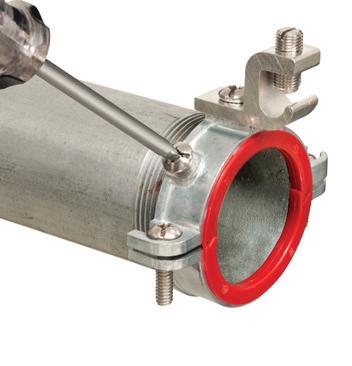
LISTED BOX EXTENDERS
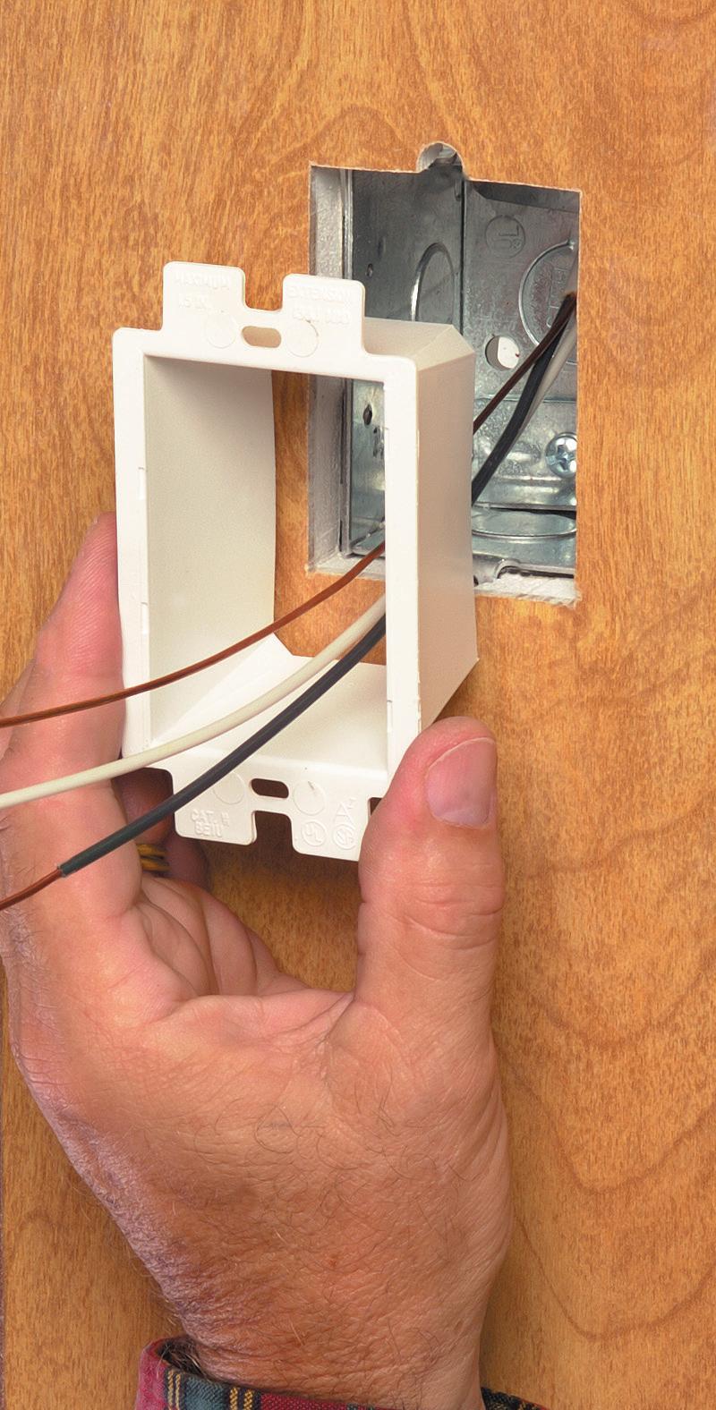
Arlington’s variety of cULus Listed Box Extenders extend set back electrical boxes up to 1-1/2”.
Made of heavy-duty, 105°C continuous use 94V0 rated, flame retardant plastic, they level and support wiring devices, while protecting wires against damage and stripping.


Choose the one that’s right for you!
BE1, BE2, BE3, BE4...Single-, two-, three- and four-gang, and BE1R for round or octagonal boxes...
Box Extenders


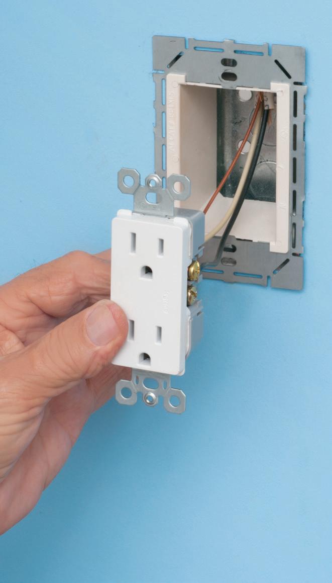
device support in oversized or mis-cut wall openings, available in single-, two-, three- and four-gang, (patented BE1X, BE2X, BE3X, BE4X.)
Our new heavy duty, COMMERCIAL-GRADE steel support plate! As shipped, the single gang BE1XLS works with maxi cover plates, but it’s Convenient. Saves time. Great for poorly cut drywall.
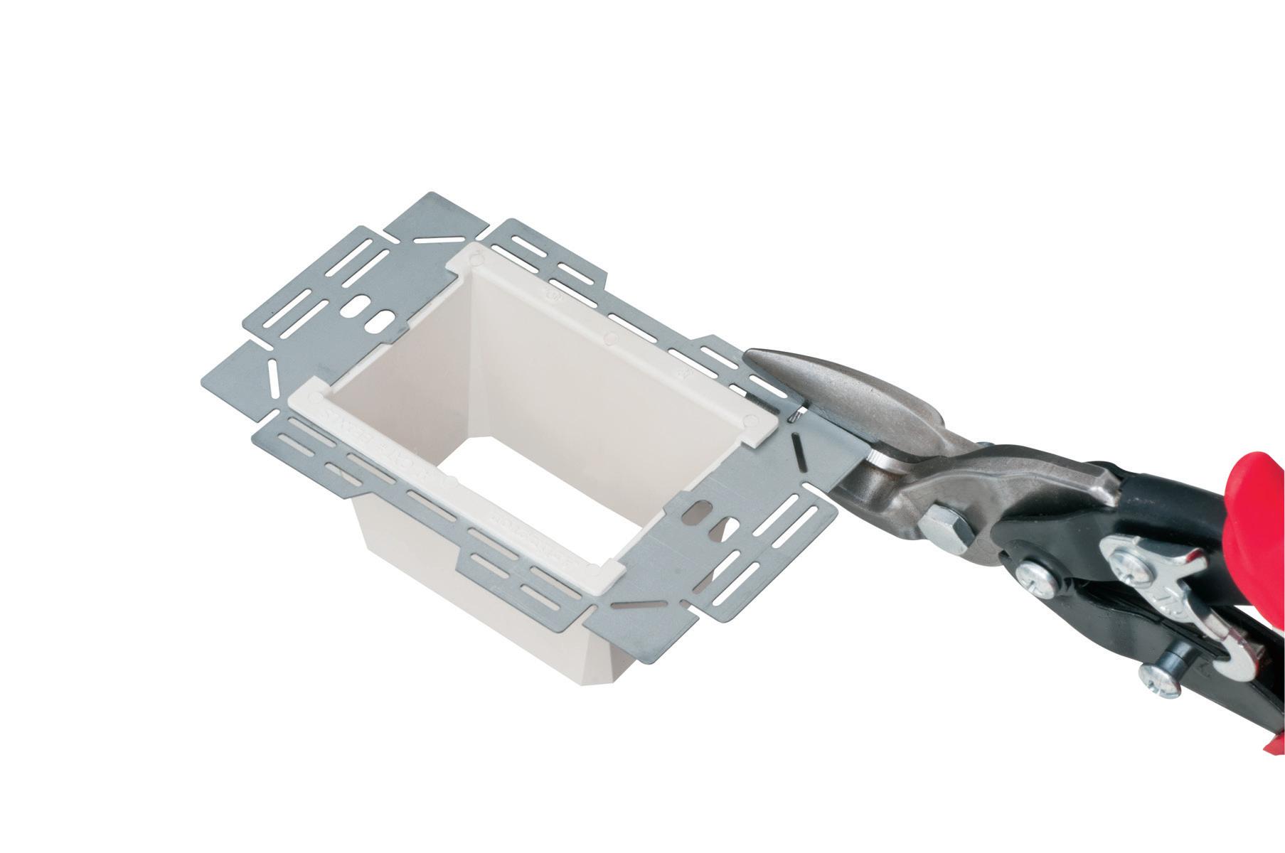
For all standard devices, switches and GFCIs, our box extenders comply with NEC Article 314.20 for set back boxes.

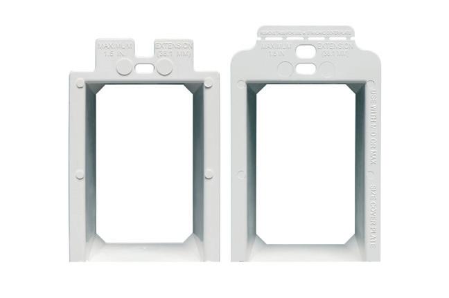

BE4 BE3 BE2 FLANGE COMPARISON BE1 BE1X
5 YEARS 7 INNOVATION NON-METALLIC • FIRE RATED © 2024 Arlington Industries, Inc. www.aifittings.com Scranton, PA 18517 800/233-4717 Product Info https://www.aifittings.com/landing/box-extender 128
MULTIPLE
for use with Metallic and Non-Metallic Boxes BE1XLS TRIMMED for MID-SIZE cover plate BE1 NEW! COMMERCIAL GRADE ...Trimmable for Mid- and Standard Wall Plates BE1XLS Single gang Patent Pending LARGER FLANGE BE2X
STYLES EXTEND SET BACK BOXES UP TO 1-1/2 INCHES
BE3X
EYE ON SAFETY
of testing “at each point of work.” This highlights the crucial aspect of conducting voltage tests directly where tasks are being carried out, further enhancing workplace safety standards.
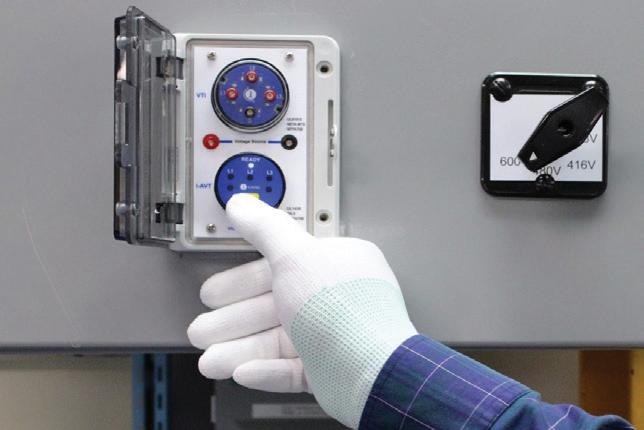
UNDERSTANDING HOW AN AVT WORKS
An individual simply presses a button to initiate a test sequence that fulfills all the requirements for verifying the absence of voltage. The AVT ensures its satisfactory function via a supervisory circuit that conducts continuity checks to confirm secure and correct connections. Only after these steps are satisfied will the AVT check for the absence of both AC and DC voltage, including phase-to-ground and phase-to-phase. If everything passes, the system repeats the steps a second time. If the second test is successful — and there is less than 3V AC or DC in the circuit — a green light(s) indicator shows the situation is safe, and the electrical panel door can be opened.
In the case of an unsuccessful test, amber light(s) stay illuminated, indicating a potentially unsafe condition. The next step is to retest the installation and wait for an additional 10 sec. If the test is unsuccessful a second time, the only option is to put on personal protective equipment (PPE), open the door, and troubleshoot the situation. This
push-to-test feature of AVTs enhances efficiency in a facility, eliminating the need for manual testing and minimizing exposure to electrical dangers.
UL 1436 Guidelines
As per UL 1436, Standard for Outlet Testers and Similar
Indicating Devices, an absence of voltage tester (AVT) is defined as a permanently mounted test device that is used to verify that a circuit is de-energized before opening an electrical enclosure that contains energized electrical conductors or circuit paths.
[1] An AVT shall be provided with the means for the user to initiate the test for the absence of voltage.
[2] An AVT shall provide the user with a visual indicator to confirm the absence of voltage after the absence of voltage test has been performed. The visual indication shall be green.
[3] The AVT supervisory circuit has incorporated a secondary power source and shall have no internal failure that would affect performance.
[4] The AVT shall incorporate a supervisory test circuit to
The AVT’s entire test sequence is visually represented in Fig. 5 on page 18. To guarantee safety and effectiveness, Section 12 of UL 1436 outlines
verify that the tester is functioning properly before and after the AVT performs voltage measurements.
[5] The AVT visual indicator shall only illuminate green when all phase-to-phase and phase-to-ground voltages measure less than 3VAC or 3VDC.
[6] The AVT visual indicators shall not illuminate green unless the phase and ground leads are in direct contact with the circuit conductors being tested.
[7] The AVT visual indicator shall not illuminate green if a phase lead is connected to ground or the ground lead is connected to a phase conductor.
[8] The visual indicator shall not illuminate green unless the secondary power source is operational.
[9] The AVT shall comply with the Standard for Functional Safety IEC 61508 and achieve an SIL 3 rating.
16 May 2024 • www.ecmweb.com
Year 0 500 1,000 1,500 2,000 2,500 Number of Nonfatal Injuries 2011 2012 2013 2014 2015 2016 2017 2018 2019 2020
Fig. 3. The number of electrical-related injuries has remained fairly consistent over this time frame.
Fig. 4. Nonfatal work injuries caused by exposure to electrical injuries by worker years of service.
0% 5% 10% 15% 20% 25% 30% 35% 40% Less than 3 months 3 months
11 months 1 year
years More than 5 years Years of Service
to
to 5
Source: ESFI


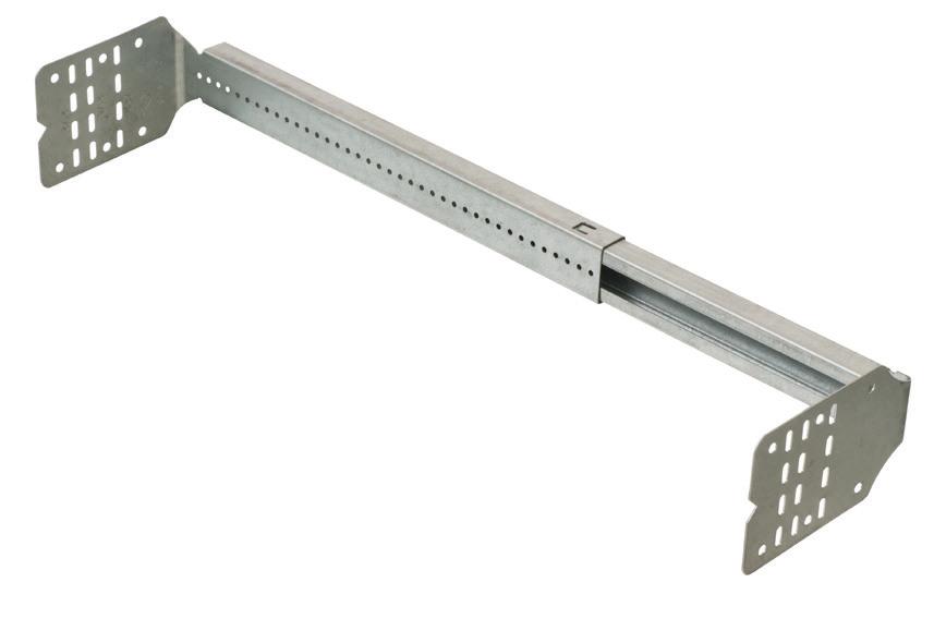
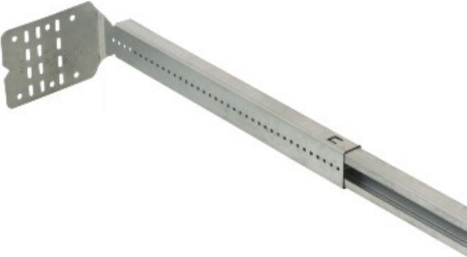


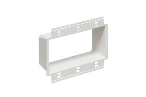
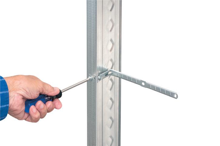
Arlington’s steel SliderBar™ offers the easy, NEAT way to mount single or two-gang boxes between wood or metal studs with non-standard stud cavities.
No more cutting, nailing and fitting extra 2x4s to fill the space! SliderBar saves about 20 minutes per box. Designed for studs spaced 12” to 18” apart, SL18 allows positioning of one or more boxes anywhere in the stud cavity.
• Bending guides on bracket assure proper positioning on studs
• Interlocking tab stop prevents accidental disassembly


• Pre-punched pilot holes on BOTH sides of S for easy attachment of one or two boxes
X 5 YEARS 7 INNOVATION LOOKS GREAT • SAVES TIME © 2024 Arlington Industries, Inc. www.aifittings.com Scranton, PA 18517 800/233-4717 Product Info https://www.aifittings.com/landing//sliderbar 127 ADJUSTABLE SLIDERBAR™ POSITIONS BOX ANYWHERE IN NON-STANDARD STUD CAVITY SLIDERBAR and one single gang plastic box. SL1B18 Patent Pending SAVES 20 MINUTES PER BOX ADJUSTABLE SLIDERBAR fits 12” to 18” stud cavity SliderBar and SliderBar kits are available with pre-bent or flat bracket ends in two sizes. SL18 fits studs spaced 12” to 18” oc. SL24 fits 15 to 24 inch o.c. spacing. Plastic boxes also sold separately.
EYE ON SAFETY
Supervisory circuit verifies the phase voltage lights are off.
Supervisory circuit verifies that the voltage source is sufficient to conduct the test.
Test to verify that DC voltage is less than 3V, phase to phase and phase to ground.
Conduct connectivity check to ensure all cables are connected correctly.
Supervisory circuit validates that the tester is functioning satisfactorily after completing absence of voltage test.
the operational standards for AVTs. These guidelines include specific testing procedures and requirements, mandating compliance with Functional Safety IEC 61508 and SIL 3 certification. SIL 3 certification underscores the fail-safe nature of the product, signifying that the occurrence of a hazardous condition must happen less than once in 10,000,000 hours of operation, on average. This rigorous criterion implies a potential failure rate of less than one instance in more than 1,000 years.
AVT BENEFITS
AVTs reduce the likelihood of human error in verifying the absence of voltage.
Supervisory circuit verifies the sensor leads are connected.
Test to verify that AC voltage is less than 3V, phase to phase and phase to ground.
Conduct connectivity check to ensure all cables are connected correctly.
Test to verify that DC voltage is less than 3V phase to phase and phase to ground.
Visually indicate results of absence of voltage test.
Unlike traditional methods that may involve physical contact with live parts, AVTs offer a non-contact solution, minimizing the risk of accidents.
The display unit of an AVT is mounted on the door and connected to the control module through a communication cable, ensuring that no hazardous voltage reaches the door. The tester is installed on the load side of a disconnect switch, with no connections to the line side. When operational, the device has no more than 3V.
AVTs should instill confidence in workers by providing a reliable and standardized method for verifying deenergization. This confidence should
Supervisory circuit verifies that the energy level on the bus is low enough to conduct the test.
Conduct connectivity check to ensure all cables are connected correctly.
Test to verify that AV voltage is less than 3V, phase to phase and phase to ground.
Conduct connectivity check to ensure all cables are connected correctly.
contribute to a positive safety culture within the workplace.
CONCLUSION
AVTs play a pivotal role in enhancing electrical safety by providing a reliable and standardized method for verifying the absence of voltage. Its accuracy, user-friendliness, and integration with safety procedures make the device a valuable tool for reducing electrical hazards and fostering a safe work environment.
Sudhir Pandey is an electrical engineer for I-Gard Corporation in Mississauga, Ontario. He can be reached at spandey@i-gard.com.
18 May 2024 • www.ecmweb.com
Fig. 5. The sequence of operation for an absence of voltage tester.
VAPOR BOX for Devices


Designed for devices, Arlington’s economical single and two-gang Vapor Boxes offer easy nail-on installation in new construction. These cost-saving boxes don’t include gaskets, but when caulked around the NM cable during installation, they meet the requirements of NEMA 0S-4 And help meet International Energy Conservation Codes (IECC), and other codes where required.


• Nails ship captive –Plugs and NM cable connectors supplied 2-hour Fire Rating


In a tight spot? Arlington’s new SNAP-TITE® Transition Fitting offers the time-saving solution for installing additional conduit or cable in an already congested panel. It allows installers to work around tightly spaced, installed fittings in a panel, box or enclosure – where installing and tightening additional locknut fittings would be next to impossible.
Convenient, Time-Saving 2450ST snaps into a 1/2" knockout and connects 1/2" trade size threaded fittings or pipe.


ARLINGTON 75 © 2020 Arlington Industries, Inc. 800/233-4717 • www.aifittings.com Product Info aifittings.com/landing/fn101fx-fn102fx/
ECONOMICAL SINGLE and TWO-GANG NON-METALLIC NAILS TO STUD IN NEW CONSTRUCTION Patented FN102FX Two-gang 40.5 cu in vapor box
nails FN101FX Single gang SAVE! WITH THESE COST-SAVING BOXES NEW Forhelp obtaining ENERGY STAR rating Made in USA
Captive
113 3/20/24 11:52 AM 800/233-4717 • www.aifittings.com aifittings.com/landing/2450st SAVES TIME • LISTED ALLOWS CABLE, CONDUIT INSTALLATION IN TIGHT SPACES TRANSITION FITTING © 2023 Arlington Industries, Inc. 123 Patent pending C
Threaded pipe Threaded fittings 2450ST Dry Location Only 2312ECM_Arlington_866403-1223_123.indd 1 11/14/23 11:51 AM
ELECTRICAL TESTING EDUCATION
Understanding Online Cable Partial Discharge Testing
How to test cables online to identify suspect cables for further study
By William G. Higinbotham, EA Technology LLCAnew hyper-scale data center was built in rural New Jersey that’s served by more than 100 25kV cables. Six months into operation, a cable termination failed catastrophically, and the forensic investigation determined that termination workmanship was lacking. Partial discharge caused tracking, and the cable flashed over. But that’s not the nightmare scenario. The nightmare scenario was that the same team of jointers terminated all 100 cables, and the owner had no idea if they are all on the edge of failure or if this was the only bad cable.
The owner was left with three crisis response options in this hypothetical situation:
• Shut the data center down for weeks or longer, and test every cable.
• Bury their heads in the sand and hope they have no more failures.
• Test all the cables online to identify any suspect cables for further study.
By examining the theory behind online testing, this article will show that the third option is the only solution that is both proven and practical at reducing the impact of additional failures down the road.
HISTORY
Medium-voltage (MV) cables — specifically MV cable terminations — are one of the least reliable components of any power system. Any time you introduce the possibility of human error into a closed system, you increase the risk of detrimental outcomes.
Cable failures are caused by subpar workmanship at the terminations twothirds of the time. This is due to a variety of reasons, including the fact that doing a field termination is a technically
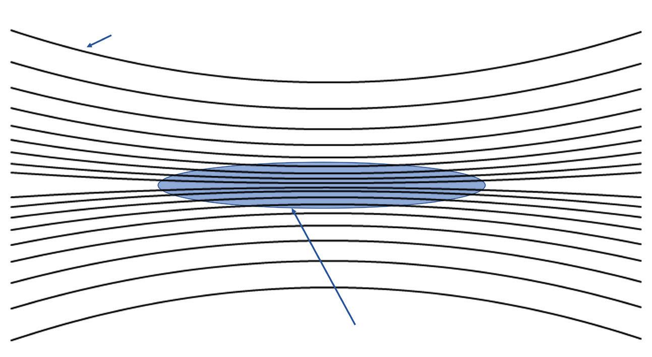
1. A higher concentration of voltage stress will appear where the cable insulation has an air-filled
challenging job in a less-than-ideal working situation. Minor mistakes can result in hidden problems that may not manifest themselves until years later.
Traditionally, cable testing occurs in two different forms over the life of the cable: pre-commissioning testing and maintenance testing.
20 May 2024 • www.ecmweb.com
Equipotential lines
Electrical stress concentrates on void because air has lower permittivity
Air filled void
“XLPE Insulation”
Fig.
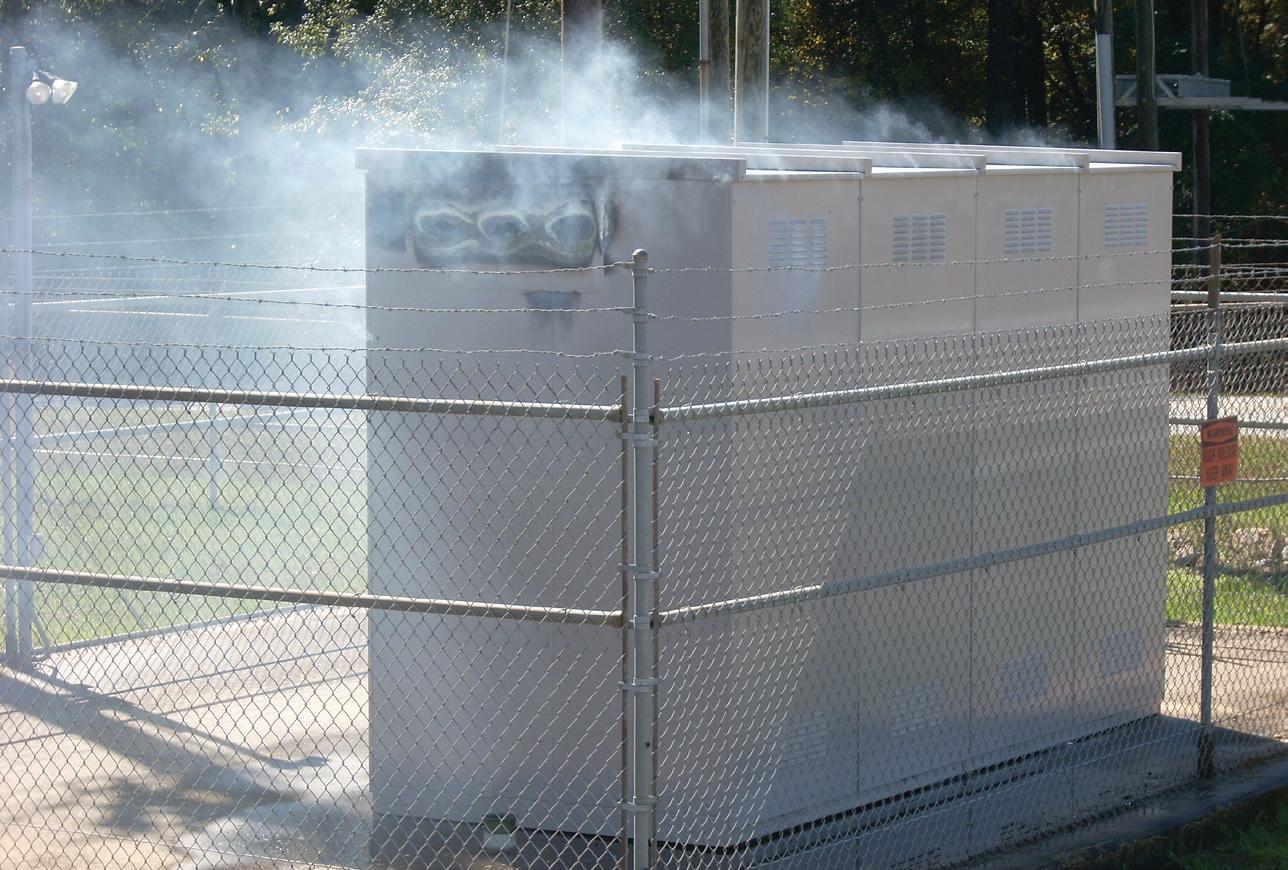
void.
This padmount switchgear failed due to partial discharge.
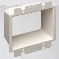
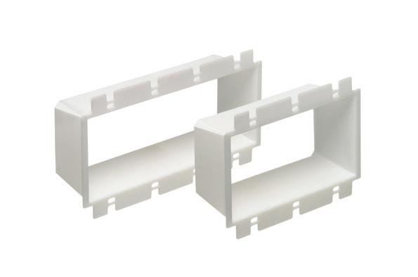
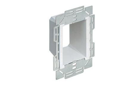
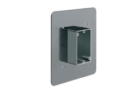
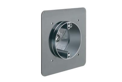
WIDE FLANGED BOXES

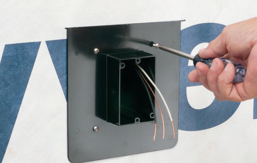
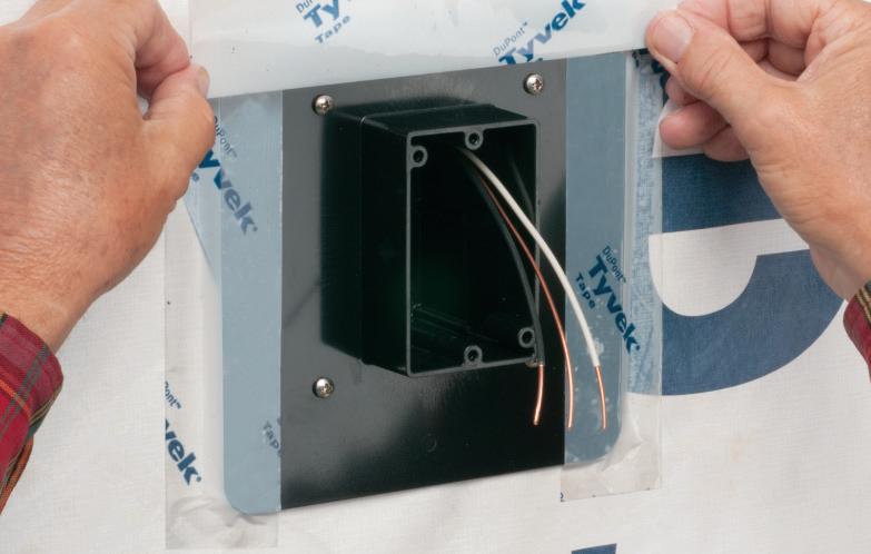
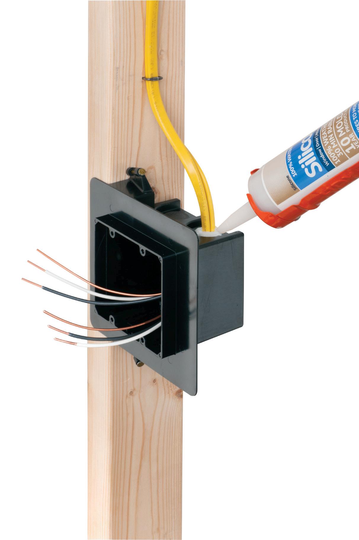
Designed for new construction, Arlington’s non-metallic FR series device and fixture boxes mount directly to a flat surface without the need to cut an opening in the substrate. They feature interchangeable backs and extension rings so ONE box works with almost any cladding system – including engineered foam/stucco systems.
Extra-wide flanges prevent water and air-intrusion, helping to meet the International Energy Conservation Code, and eliminating the need for gaskets or caulking.
• FR series boxes ship ready for use with 1-3/8” finish or cladding thickness Depth can be set for custom depth finishes or cladding materials up to 1-7/8"
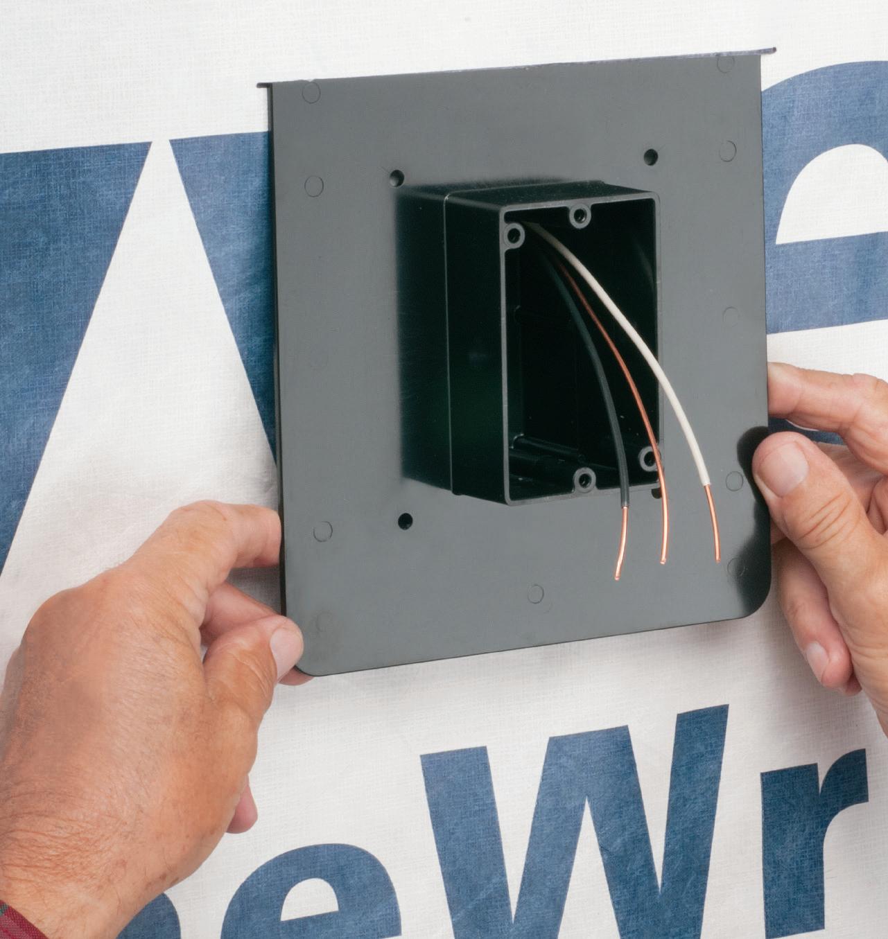
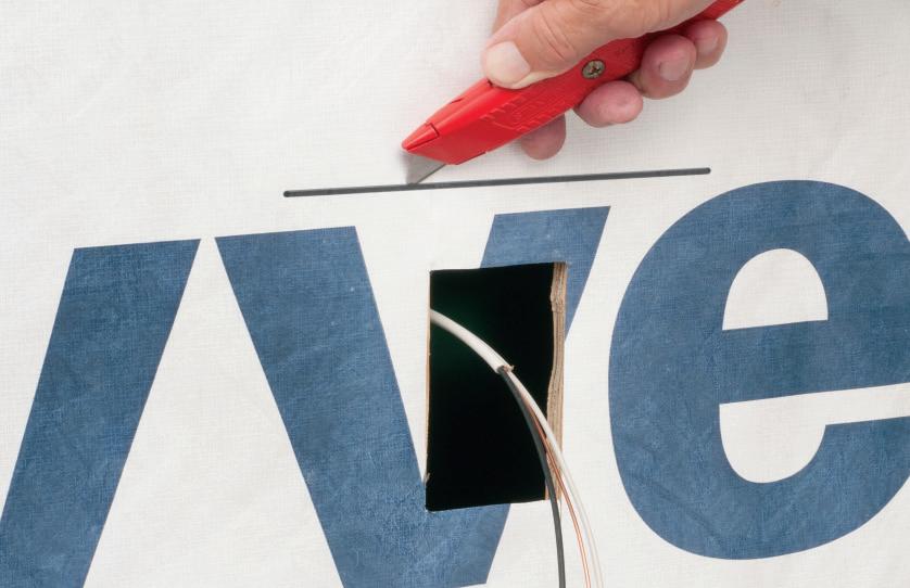
• Install before or after the weather barrier house wrap - Installation of box before the house wrap at right
• 20 cu inch volume


5 YEARS 7 INNOVATION ONE-PIECE • FOR ALL CLADDING • NON-METALLIC © 2013, 2024 Arlington Industries, Inc. www.aifittings.com Scranton, PA 18517 800/233-4717 Product Info https://www.aifittings.com/landing/fr_series/ PREVENT WATER & AIR INTRUSION • SAVE TIME Patented Fast,
Extra-wide
prevent water
intrusion... Eliminate the need for gaskets and caulking! 21 3 4
easy installation!
flanges
and air
FR101F for Devices FR420F for Fixtures up to 10 lbs FR405F Pan Box for Fixtures
Forhelp
ENERGY SAVINGS Codes
inmeeting
ELECTRICAL TESTING EDUCATION

Electrical Testing Education articles are provided by the InterNational Electrical Testing Association (NETA), www.NETAworld.org. NETA was formed in 1972 to establish uniform testing procedures for electrical equipment and systems. Today, the association accredits electrical testing companies; certifies electrical testing technicians; publishes the ANSI/NETA Standards for Acceptance Testing, Maintenance Testing, Commissioning, and the Certification of Electrical Test Technicians; and provides training through its annual PowerTest Conference and library of educational resources.
• Pre-commissioning tests include conductor resistance, insulation resistance, dielectric withstand, tan-delta, and shield continuity. Occasionally, offline VLF-based partial discharge testing is done.
• Maintenance testing is performed to find problems that can occur or worsen over time. In highly critical applications where cables can be temporarily removed from service, the same tests performed at commissioning are performed again at slightly reduced values to avoid stressing the cables. While this testing does identify concerns, it is disruptive.
As technology has developed, online maintenance testing has emerged as the ideal first line of defense in cable maintenance. Online maintenance testing is ideal because it does not impact operations and is therefore much less disruptive and less expensive than other alternatives. Online testing can provide information that allows further investigation. Online testing is typically limited to:
• Conductor resistance is an incredibly important piece of information to have. High resistance can
2. Single-phase ground test with no filter.

3. Combined ground test with no filter.
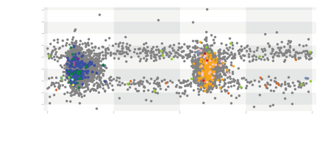
Fig. 4. Combined ground test with filtering.
result in failure quite quickly. High resistance is usually a result of poor termination crimping or shear-bolt installation and can worsen over time. This is easily detected online using infrared (IR ) inspection. Using IR to inspect terminations can detect temperature rise due to high resistance. This type of testing is widely used at all voltages.
• Online partial discharge (PD) testing can find insulation problems that exist upon initial energization as well as those that have developed or worsened over time.
THEORY
Although not widely known, PD in cables is a well-understood phenomenon that can lead to failure at any time. In a power system, if the voltage applied (KV/mm) exceeds a section of the insulation’s ability to withstand it, a discharge occurs. If the problem is the entire insulation system, a total catastrophic discharge occurs. If it’s only part of the insulation, a much smaller, short-duration, low-energy discharge occurs. This discharge damages the insulation further and will lead to a full discharge if left untreated. Detecting partial discharge
22 May 2024 • www.ecmweb.com
Phase Angle (degrees) Amplitude (pC) 20,000 0 90 180 270 360 10,000 0 -10,000 -20,000
Amplitude (pC) 30,000 20,000 10,000 -10,000 0 -20,000 -30,000 0 90 180 270 360 Phase Angle (degrees)
Fig.
Amplitude (pC) 5,000 4,000 3,000 -1,000 0 -2,000 -3,000 0 90 180 270 360 Phase Angle
Fig.
(degrees)
2,000 1,000
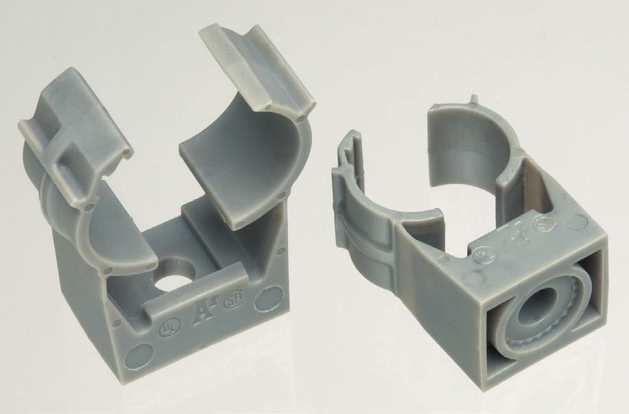
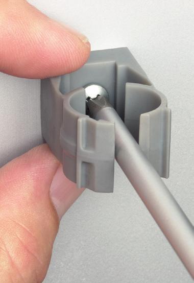
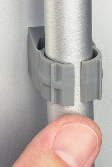
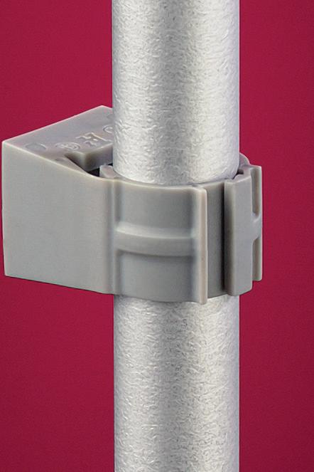
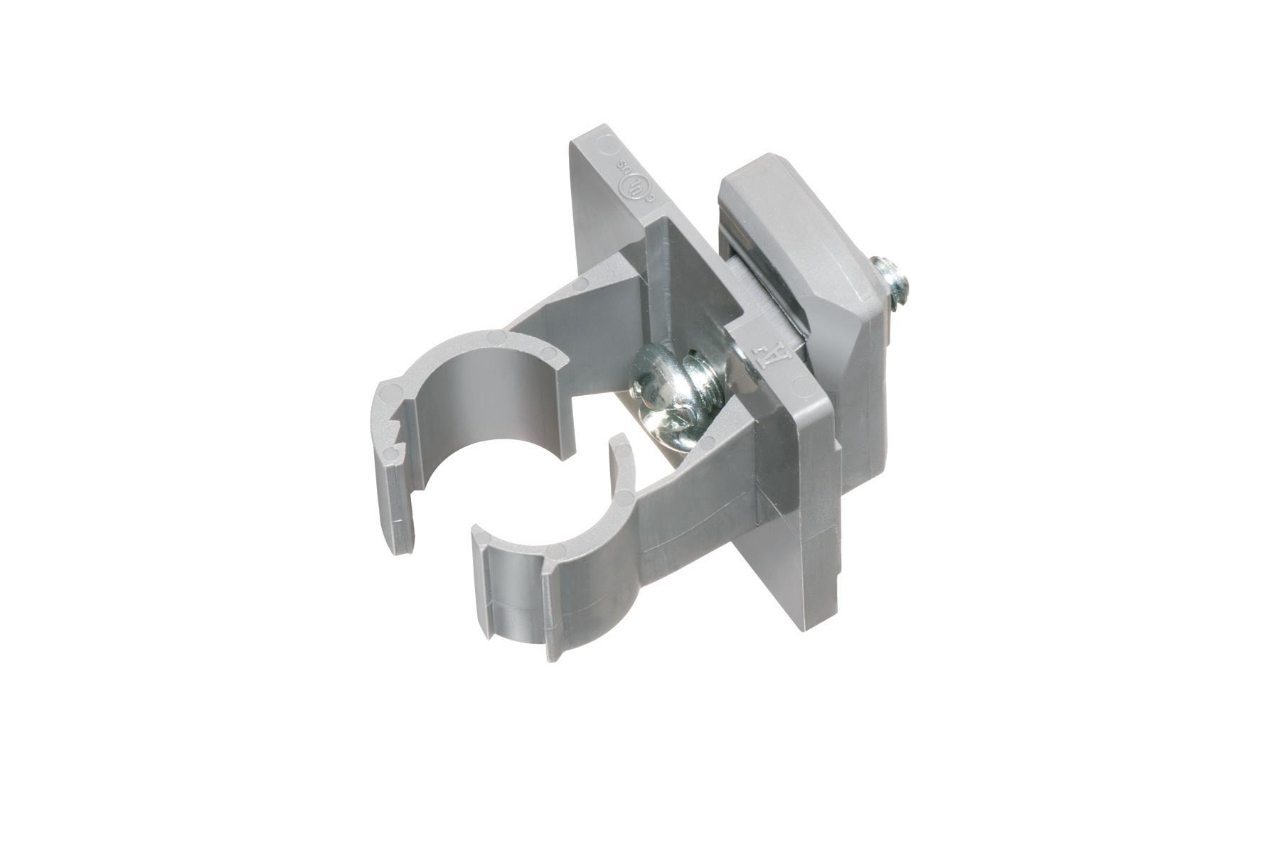
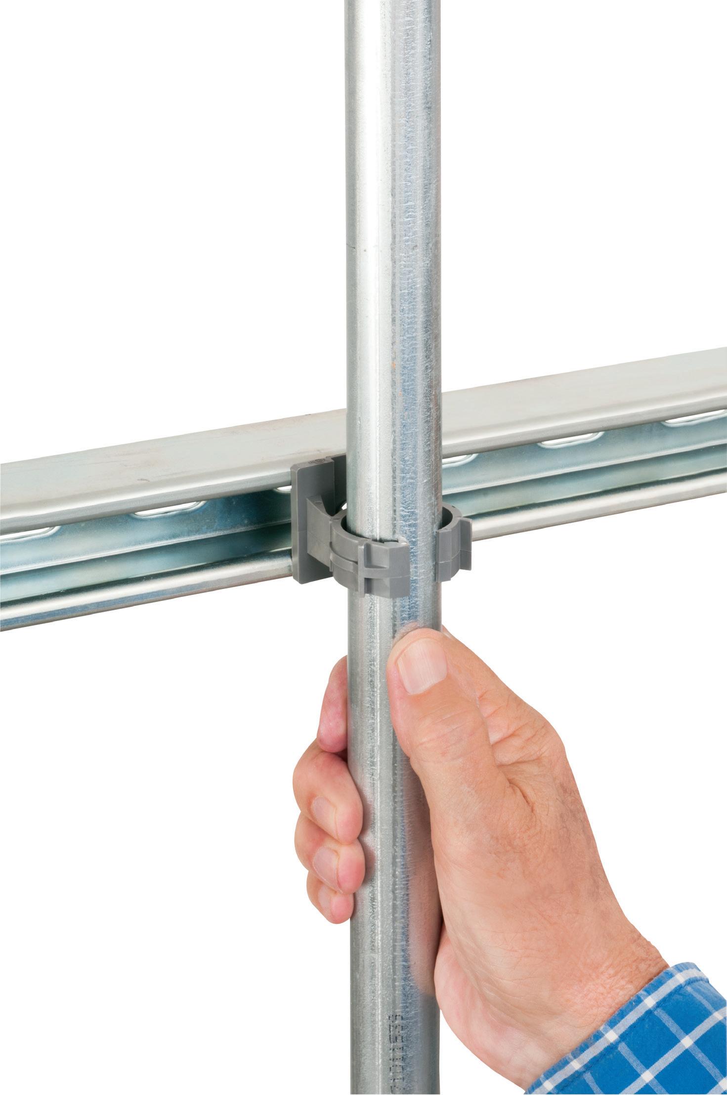
Extra-duty one-piece design
Pre-installed strut clip for faster installation on strut Stainless steel screw
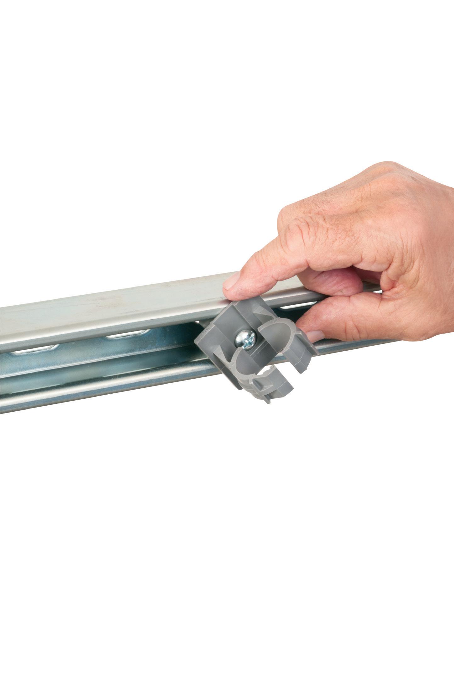
Arlington’s corrosion-resistant QUICKLATCH™ pipe hangers cost the same as a steel pipe hanger with a bolt and nut – but better. They’re faster and easier to install. And SAVE 25 seconds* per installation!
• UV rated for outdoor use
• Listed for environmental air handling spaces
• For thin walls, rigid conduit, PVC conduit or copper
Q UICK L ATCH ™ SAVE TIME... ONE-PIECE • NON-METALLIC © 2023 Arlington Industries, Inc. www.aifittings.com Scranton, PA 18517 800/233-4717 Product Info aifittings.com/landing/quicklatch_series NEW! EASY TO USE PIPE HANGER • NOW WITH INSTALLED STRUT CLIP
4” Mounts to wall, strut, stud or threaded rod NEW
series for RIGID, IMC, PVC –
1/2” to
NM3100
Patented
SAVES 25 SECONDS per Installation!
ELECTRICAL TESTING EDUCATION
can allow the asset to be repaired before it fails, causing loss of load.
If the insulation system is completely homogeneous, the voltage field distribution is perfectly even — and the only discharge that can occur is a total flashover. If the insulation is not homogeneous — by that, I mean part of it has higher or lower permittivity — the voltage distribution will not be even. This can occur due to inclusion in the insulation, damage to the insulation during installation, or improper use/construction of terminations to control the electrical field as it transitions out of the cable insulation at connection points on the equipment. A higher concentration of voltage stress can occur on a smaller (and potentially weaker) part of the insulation. This section with higher stress can then discharge and be damaged.
An example of this can be seen in Fig. 1 on page 20, which shows the distribution of voltage across an insulator with an air-filled void. This void is exposed to a higher voltage gradient due to the air having lower relative permittivity than the XLPE insulation. If the high-voltage gradient exceeds the withstand of air, partial discharge will occur across the void. The problem is compounded by air having a lower dielectric strength than XLPE.
TOOLS
Thankfully, partial discharge occurring within the insulation or termination of a cable can be detected with a variety of online tests:
• Ultrasonic testing. PD near the surface of a cable termination causes

air- and structure-borne ultrasonic energy to be released.
• High-frequency current transformer (HFCT) testing. Partial discharge can induce currents down the shield and the cable conductor at a higher frequency
than the power signals. By attaching an HFCT to the ground shield of a cable, these signals can be identified and monitored.
• Transient earth voltage (TEV) testing. PD currents cause transient voltage spikes on grounded surfaces such as
24 May 2024 • www.ecmweb.com
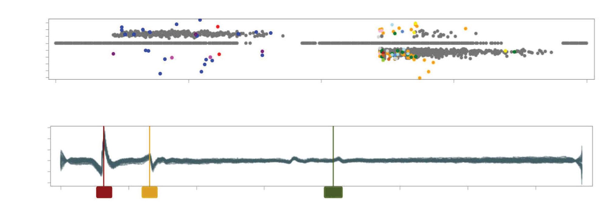
1,500 Amplitude (pC) 500 -500 -1,500 -2,500 0 90 180 270 360 Phase Angle (degrees) 6,000 4,000 2,000 0 -4,000 -2,000 Amplitude (uA) 0 5 10 15 25 30 35 Time ( s) 3.20 6.55 20.08 Events Waveforms
pC -7,500 -5,000 -2,500 0 2,500 5,000 7,500 0 90 180 270 360 Degrees <0 0<2 2<3 3<4
Fig. 5. HFCT results from a defective buried joint.
cB 60 50 40 30 20 10 0 0 90 180 270 360 Degrees 38.75 (230)
Fig. 6a. HFCT readings of a bad termination.
<1 1<5 5<9 9<11
Fig. 6b. TEV readings of a bad termination.
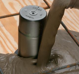
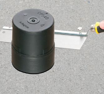
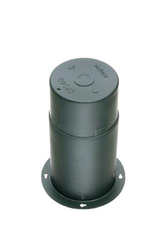
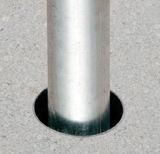
CONCRETE PIPE SLEEVE
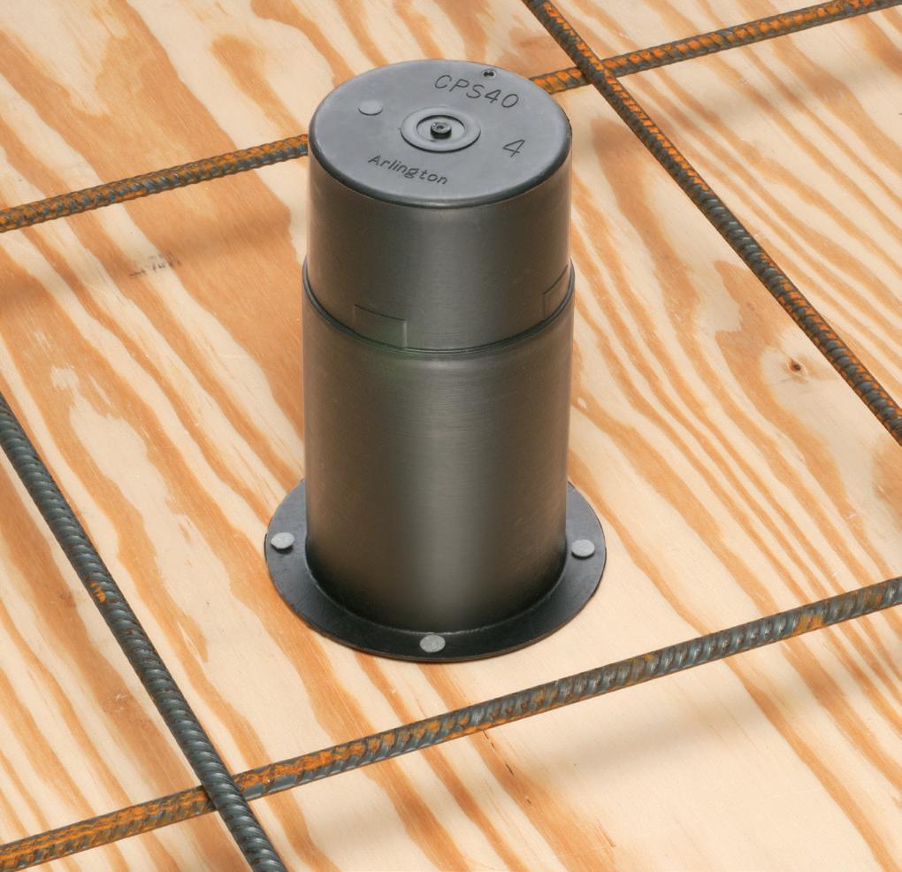
Arlington’s Concrete Pipe Sleeves are the economical way to sleeve through concrete pours in tilt-up construction WALLS – and FLOORS allowing cable and conduit to run easily from one floor to the next.
No costly core drilling – No cutting holes in the form. Plus, you can position the hole prior to pouring the concrete.
• Attaches to form with nails or screws
• Stackable up to 23" h for extra deep pours
• Vents keep wet pipe sleeves from sticking together
• Multiple hole sizes: 1-1/2" • 2" • 3"
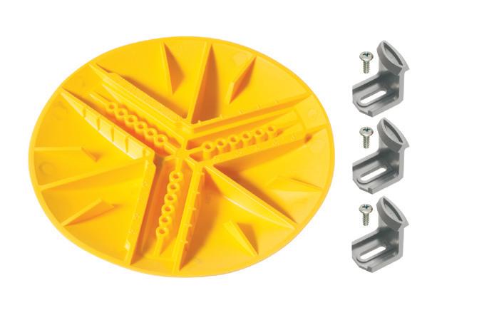
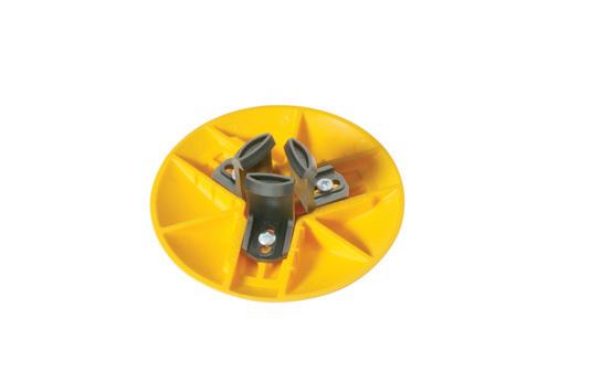
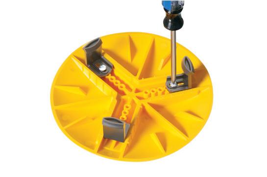
HOLE COVER KITS


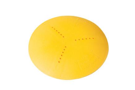

Arlington’s non-metallic hole cover kits offer the fastest way to cover a hole – and ensure compliance with OSHA safety standards on a multi-story building site.
Available in three sizes, our hole cover kits come with retaining clips that adjust to fit a range of hole sizes.
• Reference scale for precise sizing to hole diameter
• Complies with OSHA Standard 1910.28 (b) (3) (i) (A)
• Rated for 250 lb load
fits 1-3/4" to 4-1/4"
1-3/4" to 6-1/4” hole
ARLINGTON 75YEARS © 2007/REV2014 Arlington Industries, Inc.
NON-METALLIC • VENTED FOR EASIER STACKABILITY THE EASY, ECONOMICAL WAY TO SLEEVE
CPS40 Pipe Sleeve for 4" hole
THROUGH CONCRETE POURS!
CPS40
After concrete sets, cut sleeve flush with surface. Insert conduit into sleeve.
• 4" • 5" • 6"
800/233-4717 • www.aifittings.com 21 Product info aifittings.com/landing/concrete-pipe-sleeve 2312ECM_Arlington_866432-1223_21.indd 1 11/14/23 1:21 PM
Nail sleeve to form.
opening, HC1762
HC3792 © 2021 Arlington Industries, Inc. • www.aifittings.com Product info aifittings.com/landing/hole-cover-kits
HC1742
ENSURES COMPLIANCE WITH OSHA HC1742 clips set for 1-3/4" hole set for 6" hole Retaining clips RATED FOR 250 LBS Patent pending NOW IN THREE COVER SIZES • NON-METALLIC HC1762 NEW 10.5" diameter HC3792 73 2312ECM_Arlington_866437-1223_73.indd 1 11/14/23 1:46 PM
ELECTRICAL TESTING EDUCATION


8a. Phase-resolved plot of the clean termination.
cable compartment doors and cable sheaths. These can be picked up by measuring for voltage transients on the cabinet doors.
• UHF radio detection. PD causes cable terminations to emit broadband UHF spikes. Outdoor terminations are unshielded, and these emissions can be detected.
Any tool used for cable testing should be capable of multiple techniques and must also be synchronized to the power system frequency for higher selectivity. It must include algorithms to filter and discriminate PD in the presence of noise.
PRACTICAL ISSUES
A variety of issues can limit the ability to find PD in cables, but the two most prominent are access to shield ground straps and conducted noise.
In European-type switchgear, cables are terminated such that the ground straps from the shields are outside the HV compartment. In U.S. ANSI-style switchgear, the straps are entirely inside the HV compartment. This makes the application of the HFCT difficult. Permanently installing the HFCT inside the compartment or bringing the ground straps outside are the most practical solutions. Cables on riser poles are easier because they tend to have exposed grounds.

Noise can play a major role in PD detectability. Highly noisy cables like those attached to inverters or electric arc furnaces can be difficult to test. Temporarily removing the noise source may be necessary. Test equipment has a variety of tools to reduce the impact of noise, but there are practical limitations.
LIMITATIONS AND PITFALLS
Additional limitations and potential pitfalls must be considered when running online tests.
• The best online HFCT test can see only as far as the next point where the shield is grounded. If you have a cable where every splice or manhole location is grounded, you will have to test at each ground location.
Ideally, you want to test on every ground of each phase conductor separately. Physically, ground connections may make that impossible. A test on the combined ground is possible, but it typically has reduced sensitivity. Figure 2 on page 22 shows a test on a single phase. Figure 3 on page 22 shows the same test on combined grounds with no filtering. The noise is much greater and hides the PD on the combined ground. Figure 4 on page 22 shows the same combined test with some noise filtering applied. The PD is visible, but still not as clean as Fig. 2
26 May 2024 • www.ecmweb.com
dB V 0 10 20 40 50 60 0 90 180 270 360 Degrees <1 1<3 3<6 6<7 30
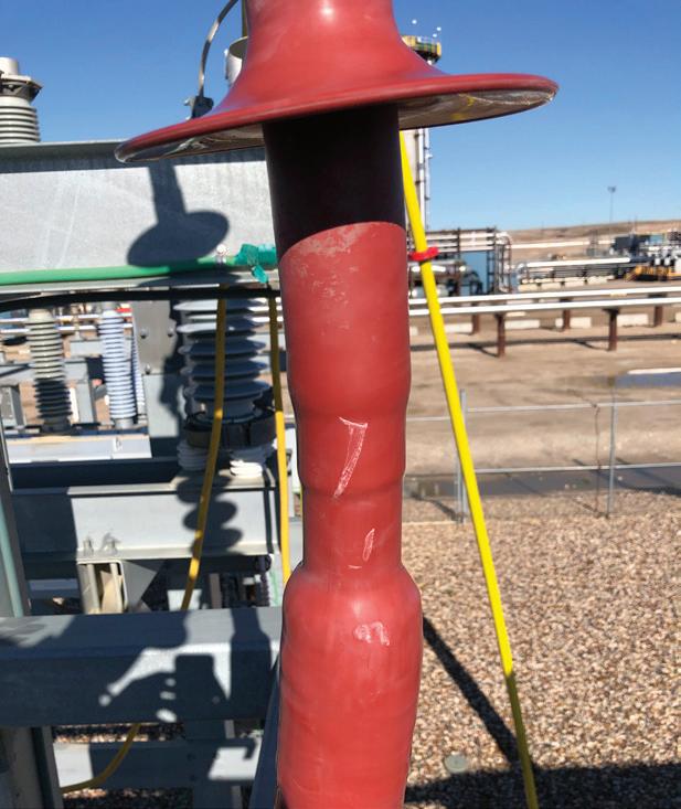
Fig. 7a. Phase-resolved plot of the contaminated termination.
Fig. 7b. Contaminated termination.
dB V 0 10 20 40 50 60 0 90 180 270 360 Degrees <1 1<3 3<5 5<6 30
Fig. 8b. Termination after cleaning.
Fig.
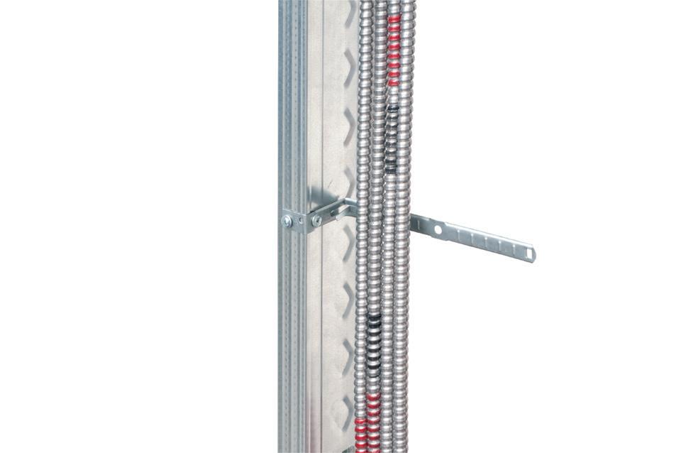
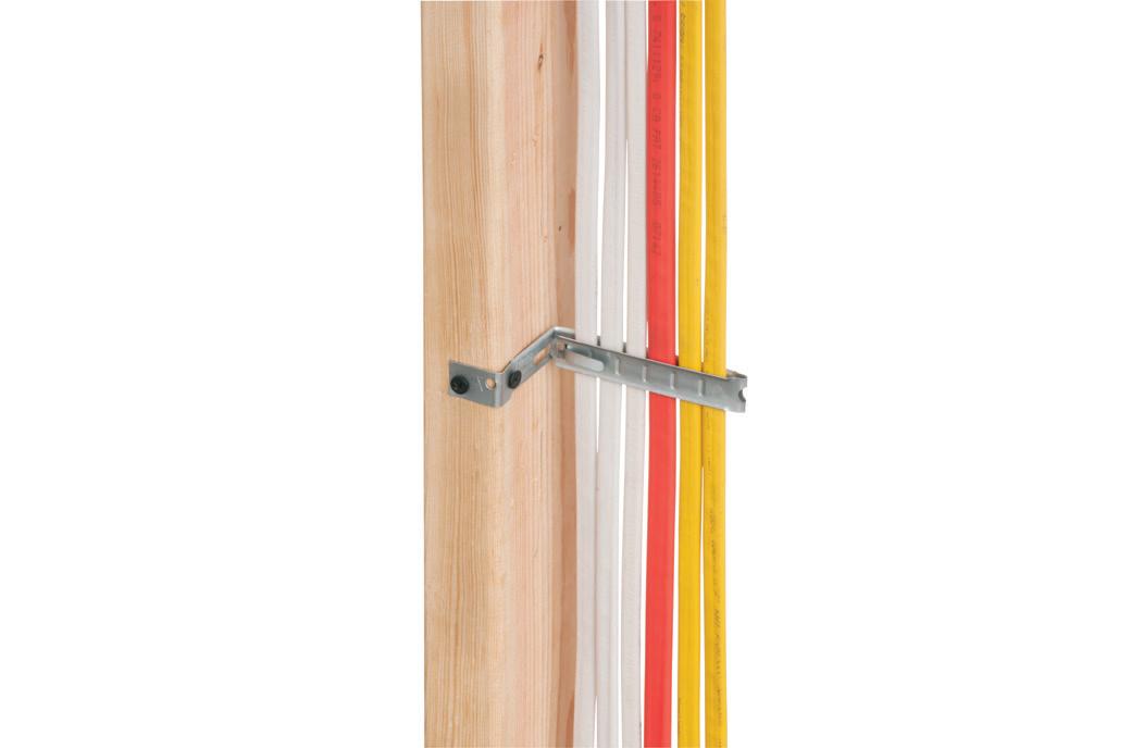
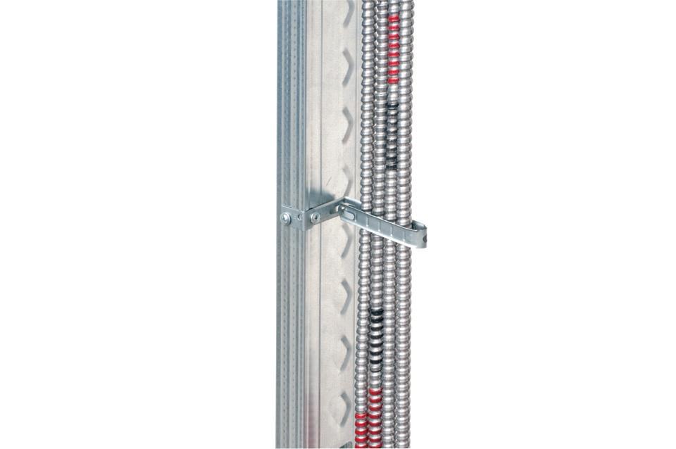
CABLE SUPPORT

Arlington’s economical CUS6 galvanized steel Cable Support holds cable secure and centered on a metal or wood stud.
It’s perfect for fastening and individual metal clad cables –or six NM cables on a 2x4. to a wood or metal stud, and position the cables. Next bend the strap at the foldline (centerline). Fold the strap over the cables and insert the locking tab in the opening as shown to hold


ARLINGTON 75YEARS
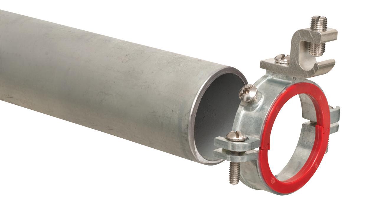
FOUR metal cables Locking tab Bend right side of strap in and over cable Foldline (centerline) Insert locking tab here Nail or screw to stud through these holes 800/233-4717 • www.aifittings.com 22 Product info aifittings.com/landing/cus6/ 2312ECM_Arlington_866442-1223_22.indd 1 11/14/23 2:20 PM 1 2 800/233-4717 • www.aifittings.com GROUNDING BUSHINGS for THREADED and UNTHREADED RIGID and IMC aifittings.com/landing/split-grounding-bushings UNTHREADED conduit 1 Loosen side screws. Allow bushing to pivot around installed cables 2 Tighten set screw to seat bushing on conduit EASY TO INSTALL Also Compatible with EMT 30A © 2023 Arlington Industries Inc. S PLIT Get convenience and time-savings with Arlington’s 550 series SPLIT grounding bushings. The split allows the addition of a bushing AFTER conductors are installed in threaded or unthreaded Rigid/IMC conduit. Great for tight spaces!
1/2" to 4" trade sizes
Compatible with EMT, 2-1/2" to 4" trade sizes, and threaded electrical fittings THREADED conduit SPLIT 2023 Category Winner 2405ECM_Arlington_915783-0524_30A.indd 1 4/22/24 10:58 AM
• In
– Ships Assembled •
ELECTRICAL TESTING EDUCATION
• TEV testing directly on the sheath of the cable near the termination is a great way to find PD, but armored or buried cables can limit the ability to do that test.
• Ultrasonic testing of terminations is very useful, but well-sealed compartments or outdoor terminations can be a challenge. Contact sensors and ultrasonic dishes can solve these problems.
• HFCT testing works well on concentric neutral and tape-shielded cables in good condition. However, if a cable has corrosion in the tape shield overlap, the shield goes from being a continuous, low-impedance path to a long helical coil. This will present higher resistance and much higher impedance to the PD current pulses. This can dramatically shorten the PD detection distance.
CASE STUDY NO. 1
A cable in Saudi Arabia was scanned using an HFCT. Not only was PD present, but the results were also so clean the tester could determine the distance to the source. A buried splice was found and confirmed with TEV testing. Once
the joint was replaced, the TEV reading showed no PD, confirming the fix. Figure 5 on page 24 shows the phaseresolved plot and the waveforms that allowed the location to be mapped.
CASE STUDY NO. 2
A cable that was only 12 months old was scanned using HFCT and TEV. Where there should have been no PD, there were massive readings. The termination was disassembled, and a shield and spring were found to be missing. Once corrected and re-energized, the TEV showed a significant drop in level, but the PD was not completely gone. Figure 6a and Fig. 6b on page 24 show HFCT and TEV readings.
CASE STUDY NO. 3
A high-voltage asset owner in central Canada had numerous terminations on substation structures. Contamination was building up unevenly on their terminations. This operator was very proactive and periodically did PD surveys of indoor and outdoor assets as part of their regular preventative maintenance.
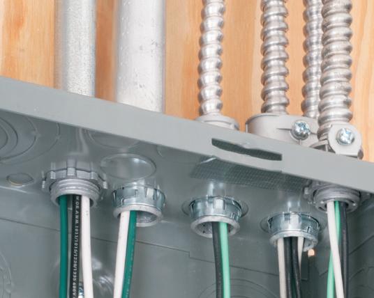
New Grand Slam home run junction box
Hit efficiency out of the park!
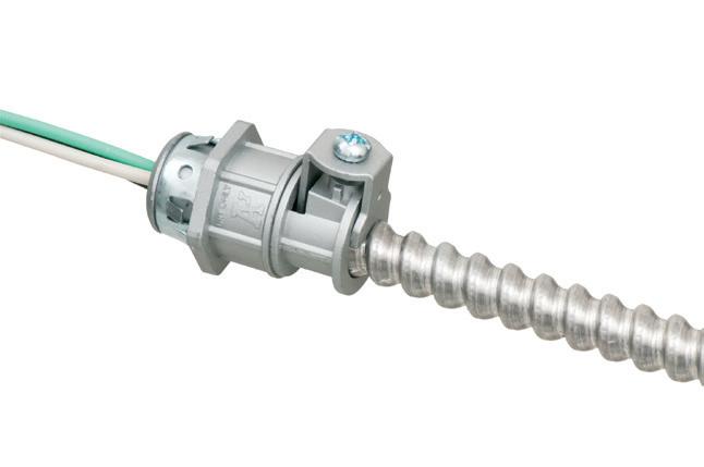
Experience the most labor savings and flexibility of any home run box on the market! The Grand Slam Box is the quickest and easiest way to terminate commercial home runs. Built-in STAB-iT® connectors are field-proven 3X faster than other MC connectors. Part of RACO’s ProReady™ solutions, driving jobsite productivity and efficiency!
• Upgraded STAB-iT® II connectors accept larger MC cable sizes
• Optional cable management and 2 multi-function clips
• Pre-installed ground bar
One of the scanned terminations returned very high levels of ultrasonic energy. The phase-resolved plots showed typical PD results. The source was frequency-locked to the power system, and the impulses occurred twice a cycle, half a cycle apart. The levels were approaching 40 dBuV, which is very high. ANSI/NETA MTS 2019 calls for immediate action on levels greater than 6 dBuV. Figure 7a and Fig. 7b on page 26 show the phase-resolved plot and the contaminated termination.
During the next scheduled outage, the insulators were cleaned and then rescanned. The ultrasonic energy was gone, proving that the discharge was a result of the contamination. Figure 8a and Fig. 8b on page 26 show the phaseresolved plot and termination after thorough cleaning.
William G. Higinbotham has been president of EA Technology LLC since 2013. He can be reached at Bill.Higinbotham@ eatontechnologyusa.com.

Order it today! Learn more about the Grand Slam Box
28 May 2024 • www.ecmweb.com
2405ECM_Hubbell_GrandSlam.indd 1 4/11/24 4:01 PM
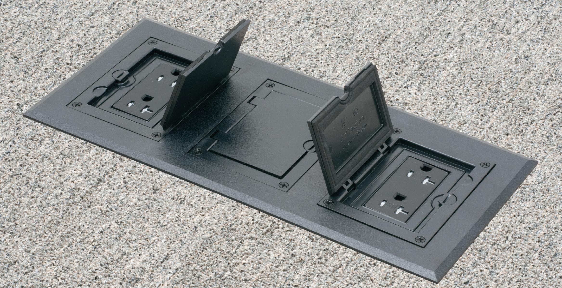
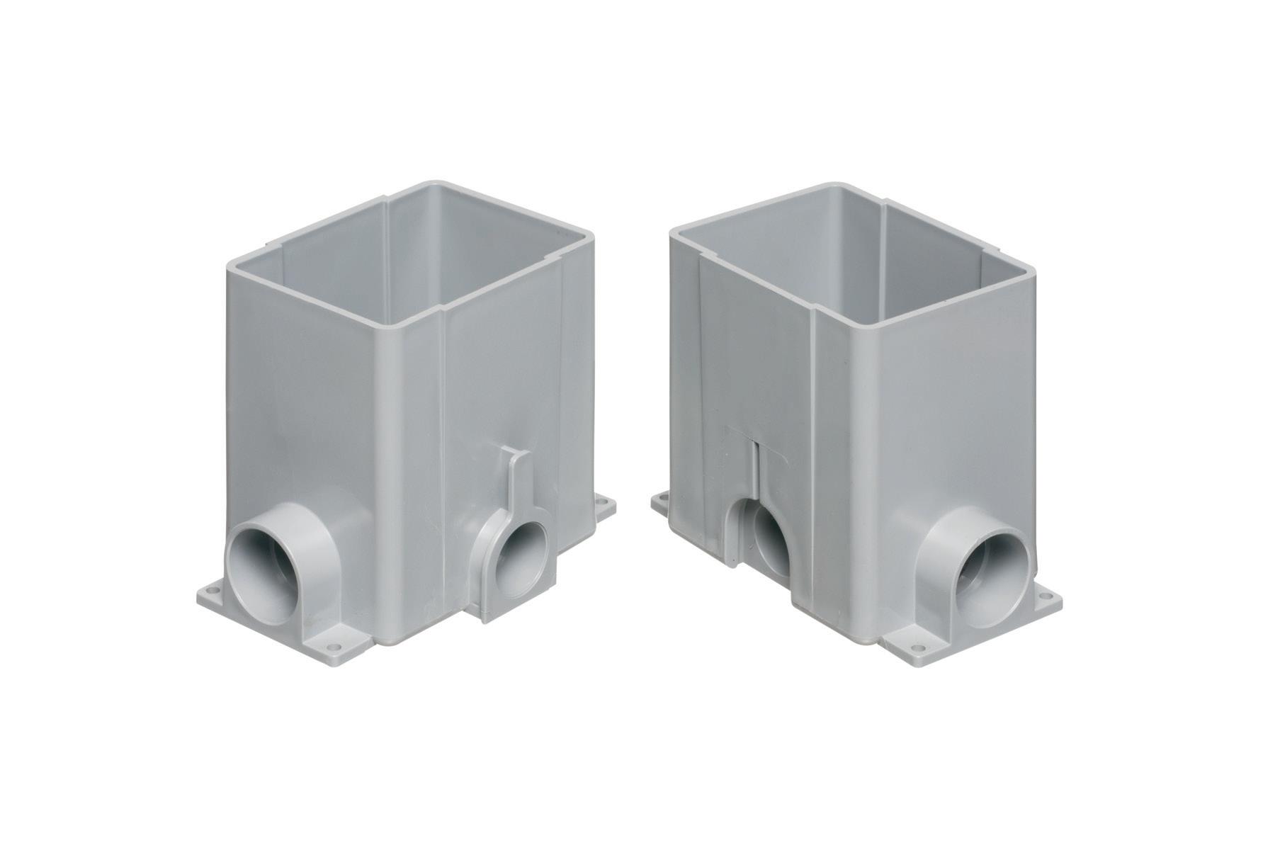
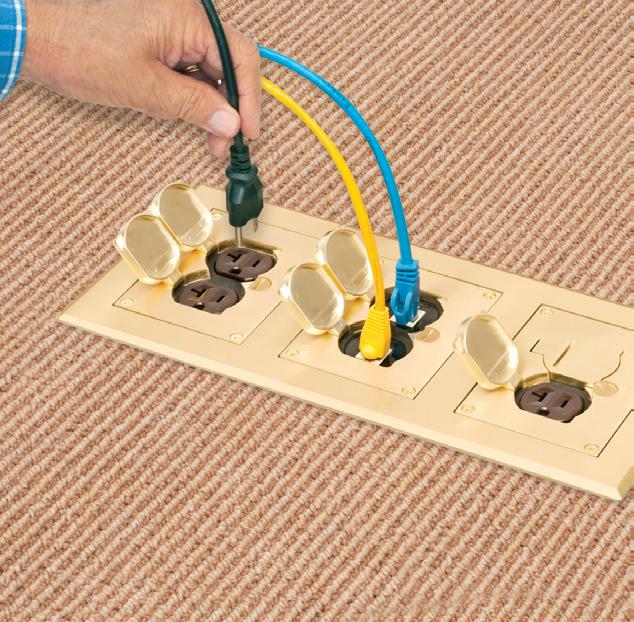
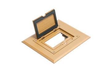
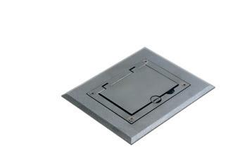
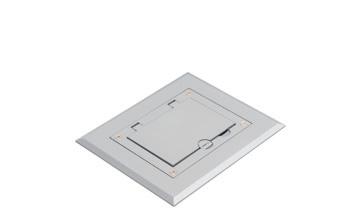
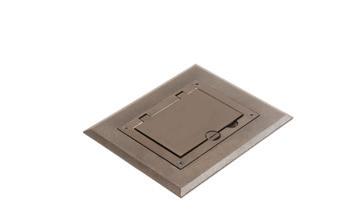
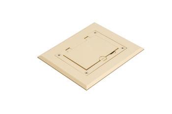
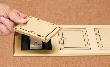
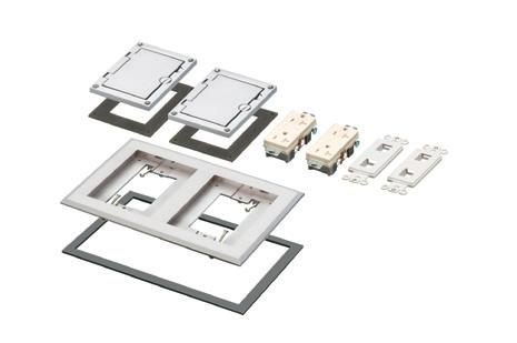
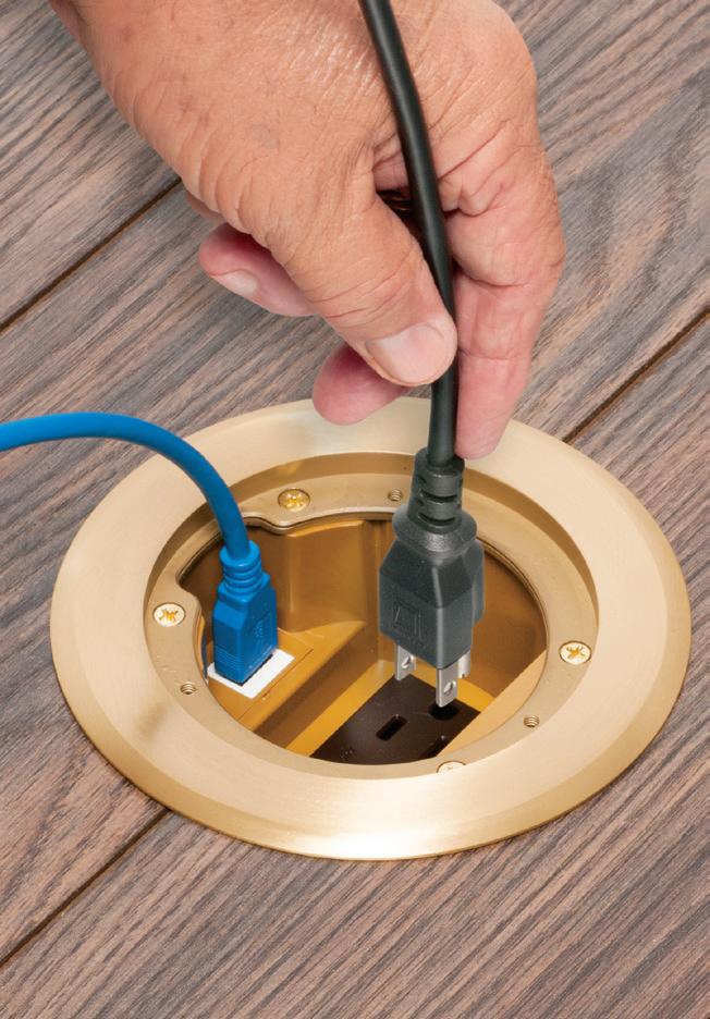
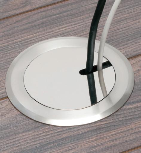
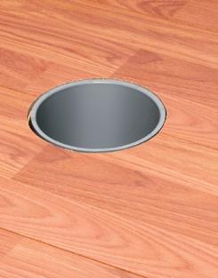
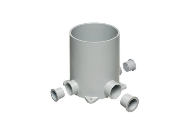
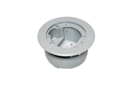
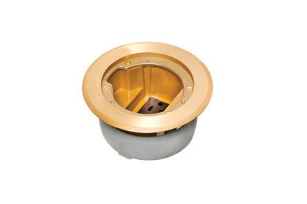
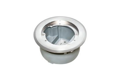
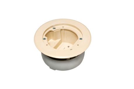
FLOOR BOX


FLBC8500 Single gang box FLBC8500
(3) FLBC8500 boxes
Cover/frame kits
in USA Plastic Cover/frame Kit
Single gang
FLBC8510BR Brown
FLBC8510BL Black
FLBC8510GY Gray
FLBC8510CA Caramel
FLBC8510LA Lt Almond
Two-gang
FLBC8520BR Brown
FLBC8520BL Black
FLBC8520GY Gray
FLBC8520CA Caramel
FLBC8520LA Lt Almond

Three-gang
FLBC8530BR Brown
FLBC8530BL Black
FLBC8530GY Gray
FLBC8530CA Caramel
FLBC8530LA Lt Almond


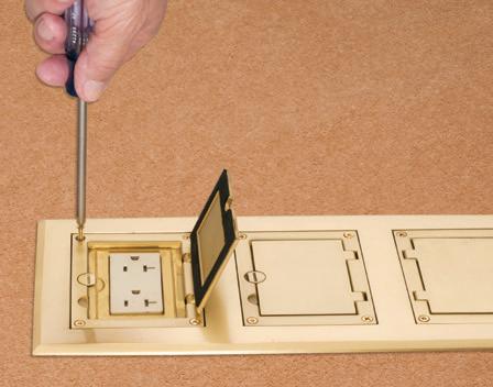
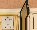
a two-gang box. Add another for three-gang!

Build a two- or three-gang concrete floor box by simply locking single gang boxes together!
Then buy the UL LISTED single, two- or three-gang cover/frame kit, with devices included, in PLASTIC, FIVE COLORS – or in economical diecast zinc with a brass or nickel finish. Fast, easy installation.
Cover installs with hinge on either side.
Cover/frame Kit


Two-gang FLBC8520MB
Three-gang FLBC8530MB
Three-gang FLBC8530NL
www.aifittings.com Scranton, PA 18517 800/233-4717 Product Info aifittings.com/landing/gangable-box-kits/ Patented Nickel finish Single gang
FLBC8510NL Two-gang FLBC8520NL
Metal
Brass
finish Single gang FLBC8510MB
(1) FLBC8530BL Black plastic cover/frame kit
Reposition hinge. It’s Easy! Remove cover Rotate. Reinstall. R Listed
NOW IN PLASTIC,
Made
Black Gray Almond
© 2017 REV 2022 Arlington Industries, Inc.
FLBC8530MB
FLBC8510BR
ECONOMICAL • INTERLOCKING FOR NEW CONCRETE FLOORS PLASTIC NEW COVERS! with FLIP LIDS Covers open in Both Directions PLATED, PLASTIC or POWDER-COATED
GANGABLE
HERE’S HOW IT WORKS... 66
Identifying Patterns on Electrical Construction Job Sites
Every project is different — or is it?
By Dr. Heather Moore and Sydney Parvin, MCA, Inc.If you have ever solved a Rubik’s Cube, you know the look of awe on faces of those who have not. The ability to go from an orderly, same-colored set of six sides to chaos of unmatching colors and then back to complete order seems to require some fancy wizardry. There are many approaches to unscrambling including:
• Dedicating hours of your life to work one cube at a time back in its original place.
• Peeling off and reapplying the stickers so you have a uniform color on each side (however, this leaves some nasty evidence).
• Recognizing the pattern in a solution, and mastering it in a matter of a few moves within minutes or seconds.
The time involved with option No. 1 usually reduces interest in trying (at least a second time). The poor-quality result of option No. 2 also leaves little to be desired. Option No. 3 becomes a solution for those who seek to categorize, codify, and find patterns to make their life easy.
What does this have to do with jobsite intelligence? The Rubik’s Cube and the “work cube” (Fig. 1 on page 32) are the same. There are only so many permutations and combinations of work in electrical construction, so mastery is a matter of pattern recognition, using experience or Agile Intelligence™ with the experience of many. Despite constantly hearing that “every job is unique,” or “we can’t use our normal approach on this job because…,” we will show you that construction jobs have more in common than not.
A project, by definition, is a temporary endeavor to create a unique product, service, or outcome. Construction projects are often characterized as

complex, special, or unique — because the deliverable is one of a kind. As new models for construction are introduced that change the way contractors, owners, general contractors (GCs), and architects interact — such as on IPD or GMP projects, this can add another layer of uncertainty.
What makes a project special? A unique project for one contractor or project manager may not be considered unique by another. MCA’s research on the Industrialization of Construction® has shown that there have been minimal changes to the construction process over the last few centuries. Yet, contractors struggle to take advantage of learning across projects, practice consistent project management processes, or even avoid expanding into new markets altogether, citing the reason that the project is “unique.”
While no two projects are the same, ignoring synchronicities and dismissing any means of control because of the project’s uniqueness can be a risky mindset. Vice versa, seeking to standardize every aspect of a project is also not the answer.
Rather, contractors can successfully expand into new markets, environments, and geographies by implementing flexibility in the organization that allows resources, information flow, and risks to be assessed and responded to across the entire operation, while maintaining control of even the one-off types of projects. Project control is essentially getting the project to go the way it is intended to. Control can be achieved through the application of project management processes and the adoption of a resilient operation. By recognizing the common patterns — and checking for these patterns across your job sites — problems or situations
30 May 2024 • www.ecmweb.com JOB-SITE INTELLIGENCE
Photo 34216831 © Trofoto | Dreamstime.com

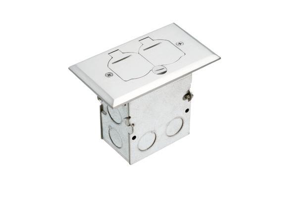

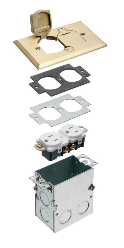
Arlington’s STEEL FLOOR BOX KITS give installers a low cost, convenient way to install a receptacle in a new or existing floor.
Listed Single Gang Steel Floor Boxes deliver easy, flush-to-the-floor installation.
• Brass covers hide miscut flooring; gaskets prevent water intrusion; flip lids protect the box when it’s not in use.
• Single gang brass and nickel-plated Brass Covers fit our boxes and other manufacturers’ single gang boxes. Covers also sold separately.


ARLINGTON 75YEARS
BOX
BRASS COVER
STEEL
WITH
CONVENIENT, FLUSH-TO-THE-FLOOR RECEPTACLE INSTALLATION FLOOR BOX KITS LISTED SINGLE GANG FLB5331MB Single gang steel box kit w brass cover © 2016 Arlington Industries, Inc. steel box kit w nickel-plated brass cover FLB5331MB Single gang Kit w brass cover for NEW or existing floors 119 800/233-4717 • www.aifittings.com Product info aifittings.com/landing/flb5331-flb5551-kits 2312ECM_Arlington_866439-1223_119.indd 1 11/14/23 1:58 PM © 2018 Arlington Industries, Inc. Plugs stay inside recessed cover Slotted in-use cover Arlington’s IN BOX® Recessed Cover Kits are the neat way to install a receptacle in an installed 4.5" concrete floor box, including our FLBC4500 or FLBC4502 boxes. IN BOX covers install fast, inside the can reducing trip hazards caused by plugs sticking out of the box. They look great. And, you can have power and low voltage in the Assembled IN BOX, comes with matching in-use slotted cover and cover blank for unused boxes in brass or nickel-plated brass INSTALLS INSIDE 4.5" CONCRETE BOXES Patented/other patents pending IN BOX COVER KITS ® RECESSED Easy to install in concrete box NEW! FLBC4560DMB FLBC4560DNL FLBC4560DBR Brown Cover blank Slotted cover FLBC4560DMB Brass FLBC4560DNL Nickel-plated FLBC4560DGY Gray FLBC4560DCA Caramel FLBC4560DBL Black FLBC4560DLA Light almond Patented FLBC4500 FLOOR BOX FOR NEW CONCRETE 57 800/233-4717 • www.aifittings.com Product info aifittings.com/landing/inbox-cover-kits/ 2312ECM_Arlington_866440-1223_57.indd 1 11/14/23 2:11 PM
JOB-SITE INTELLIGENCE
that may seem like discrete events no longer have to be resolved and managed that way.
JOB-SITE PATTERNS
Like a Rubik’s Cube, construction projects can be unscrambled by finding the patterns. MCA, Inc. has been collecting short-interval scheduling and job productivity assurance and control data from thousands of contractors on construction projects totaling more than $3 billion since 2003. The methodology and principles published in EC&M’s 2009 article, “The Secret to Short-Interval Scheduling,” allow contractors to categorize impacts to scheduled work. Read the article online at ecmweb. com/20889745.
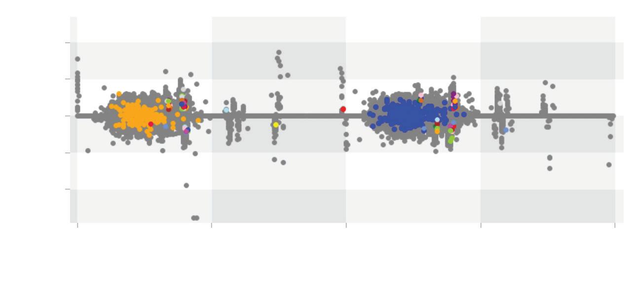
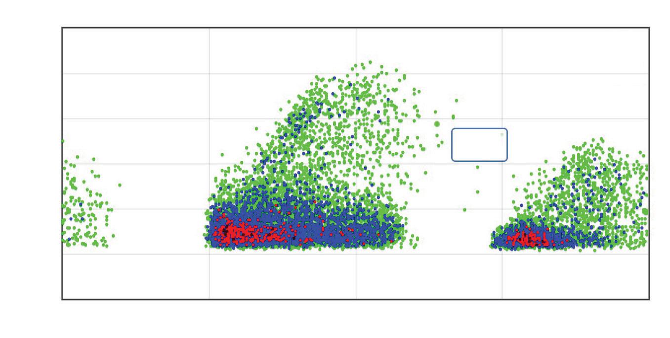
In 2019, MCA conducted a study to review the codification of obstacles across the projects and identified common reasons for impacts on scheduled work. These job-site obstacles were codified and are now referenceable in the ASTM Standard Practice for Job Productivity Measurement, E2691. Findings from the study showed that the following obstacles — independent of the type of work, contract type, and location — were prevalent and accounted for 60% (cumulatively) of obstacles industry-wide (Fig. 2): absenteeism, area not ready, trade interference, and material issues.
While your job’s contract, scope, size, location, or other factors may be unique, our data shows that the obstacles above are not, and they are part of the twists that a work cube can encounter, which need to be mastered for unscrambling and reducing wasted time and effort on any project.
IDENTIFYING PATTERNS ON YOUR JOB SITES
While every project may have a unique deliverable, the construction process and obstacles encountered along the way are common from job to job. Rather than treating each issue as a discrete event, contractors can start looking for patterns and use tools like short interval scheduling to measure and then design solutions to manage, respond, and resolve these common causes across projects company-wide.
If you aren’t using Short-Interval Scheduling (SIS®) and want to see these
TheWork
Dimensions of Work Who & Where
Fig. 1. Understanding and mastering the “work cube” will improve job-site productivity.
Fig. 2. Four types of job-site obstacles accounted for 60% (cumulatively) of obstacles industry-side: absenteeism, area not ready, trade interference, and material issues. patterns with your own eyes, visit a job site. While on site, ask yourself the following questions about each type of common job-site obstacle.
LABOR/ABSENTEEISM
• Does the labor on site match the planned work and schedule for the day?
• If people are off, what was the reason given?
• Does the labor schedule need to be updated to account for school and training schedules of part-time members of the crew?
• Are prefab or vendor services in use on the job that can help level the on-site labor requirements? Are there opportunities to put this in place to reduce the impact of absenteeism on site?
32 May 2024 • www.ecmweb.com
Test Cleanup Handle material Planning Equip. set Test & troubleshoot Install fixtures Rough-in Late/closeout Middle/peak Early/mid job Planning/beginning job
When Skill&experienceGeography/jurisdictionOnsite/offsiteVendor/prefab
Industry
Percent of Total 30% 100% 80% 60% 40% 20% 0% Cumulative Percent 25% 20% 15% 10% 5% 0% Absenteeism Trade interference/trade stacking Area not ready Material Underestimated scheduled work Manpower shift from supervision GC/schedule issue Technical/design issues or Q’s Lack of access to area Coordination issues Labor/personnel issues Labor quality/skill issues Change orders Tools/equipment Other trades’ material in the way Weather/force majuere Housekeeping & site logistics Hours
worked
scheduled Occurences Cumulative percent ©
–
Data
© MCA Inc. and Dr. Perry Daneshgari, 2007
Wide Common Job-Site Obstacles
not
as
MCA R&D
SIS®
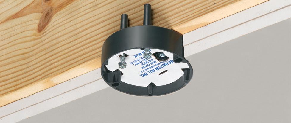
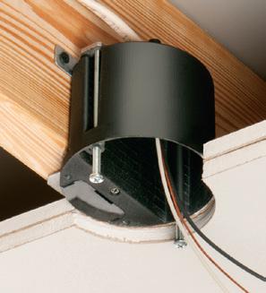
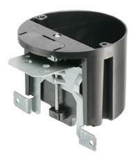
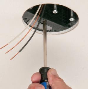
FAN/FIXTURE PAN BOX
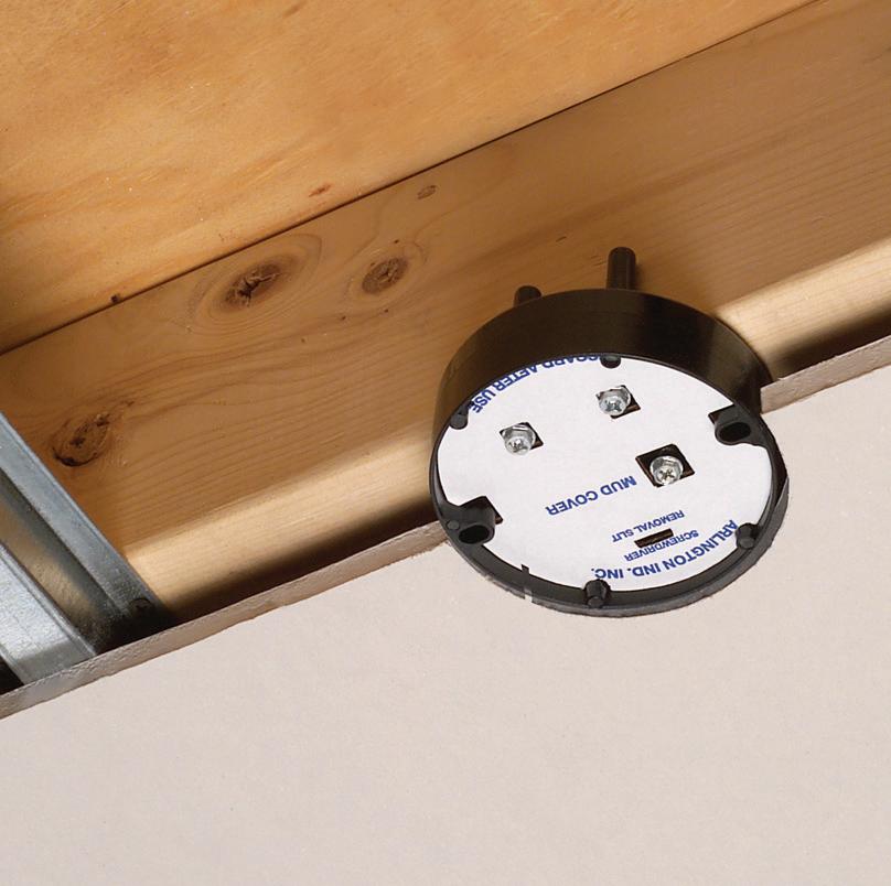
Arlington’s convenient fan/fixture pan box works with 1/2", and single or double 5/8" drywall –on furring strips or hat channel.
• Easy mounting in new work
•Fan bracket installation screws ship captive until ready for use
•Secure joist-mount installation
•14.4 cu. in. UL/CSA Listed

Product info aifittings.com/catalog/fan-fixture-boxes/fan-fixturemounting-boxes-for-drywall-with-furring-strips-or-hat-channel/FB412

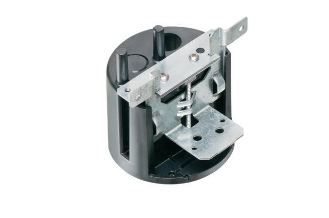
Arlington’s IN/OUT™ fan/fixture boxes adjust up to 1-1/2" to accommodate varying ceiling thicknesses, like single or double FBA426 is Listed for fans up to 70 lbs; fixtures up to 100 lbs. Pre-set for 1/2" ceiling – depth adjustment screw positions the box flush with the ceiling after it’s in place Complies with 2020 NEC, 314.20 for set back boxes
• (4) screws attach box securely to joist in new work • 2-Hour Fire Rating


ARLINGTON 75YEARS
© 2017 Arlington Industries, Inc. UL rated 70 lb fan • 200 lb fixture CSA 50 lb fan/fixture Captive fan bracket installation screws
SECURE, JOIST-MOUNT INSTALLATION FOR 1/2" OR 5/8" DRYWALL WITH FURRING STRIPS OR HAT CHANNEL FB412 FB412 with 5/8" double drywall * 2-HOUR FIRE RATING 32
800/233-4717 • www.aifittings.com 2402ECM_Arlington_902053-0224_32.indd 1 1/22/24 2:54 PM
© 2013 Arlington Industries, Inc. 800/233-4717 • www.aifittings.com IN/OUT BOX for Fans & Fixtures ADJUSTABLE • NON-METALLIC • 2-HOUR FIRE RATING TM FBA426 Adjustable Fan/Fixture Box 21.0 cu in NEW Bracket installation screws ship captive Depth adjustment screw 1 Cutaway: Box set back in double drywall 2 Install ceiling.
necessary
depth
ceiling. 1 2 Underside Product info aifittings.com/landing/fba426 20.5 cu in FA426 for Fixtures up to 50 lbs 6 Patented EASY TO INSTALL ... IN NEW CONSTRUCTION 27 2405ECM_Arlington_915792-0524_27.indd 1 4/22/24 11:10 AM
If
use
adjustment screw to position box flush with
JOB-SITE INTELLIGENCE
Change-Order Recognition

Job Duration:
Observed Percent of Complete Job
Fig. 3. Data shows that change-order behavior is similar no matter the size, scope, or type of job.
MATERIAL
• Where is on-site material stored/ staged?
• Where are the tools and gang boxes located?
• Is the material organized, labeled, and staged near the installation location?
• How much material is lying around the job site?
• How much movement of material is required?
• Are deliveries managed at a scheduled time?
• How often do you expect deliveries? Can this be reduced to minimize the time spent handling material?
• Are deliveries from the distributor on time?
AREA NOT READY/TRADE INTERFERENCE
• How many other trades are on site? Where are they working?
• Are the other trades working according to the GC’s schedule?
Additionally, ask yourself: How does coordination take place between the trades? Is there a daily huddle? And do
you foresee any trade interference or delays in the ability to work in one area due to the schedule being off track?
Labor is often so busy doing the work that they don’t see the obstacles. They only report problems half of the time and encounter them in nearly 90% of their work activities, as outlined in “Exploring Information Generation and Propagation from the Point of Installation on Construction Jobsites: An SNA / ABM Hybrid Approach” by Dr. Heather Moore in her PhD dissertation at Michigan State University. The SIS process solves this, with a proven process for daily scheduling of work and scoring the results. Obstacles reported become visible in real time for managers to monitor and respond to.
Another pattern across construction job sites is change-order management. With data from several electrical contractors, we have measured that projects “expand” 30% to 40% from changes — some attributable to contract changes (i.e., change orders) and some due to changes in scope and misses in estimating and planning. Managing these changes is
challenging, no matter what size, scope, or type of job you’re running. Figure 3 shows how similar the change-order behavior is across 200 projects spanning four years. Notice that change orders are recognized very similarly at each stage of project completion — almost independent of job size.
SOLVING THE CUBE
While a single project may seem unique, keep in mind that there are limited maneuvers to get a scrambled cube back in order. By studying the patterns across all your job sites with data — and backing them up with your observations on job sites — you can focus on the common pain points and be prepared to take advantage of the solutions on projects of all shapes and sizes.
Dr. Heather Moore is vice president of customer care at MCA, Inc. in Grand Blanc, Mich. She can be reached at hmoore@mca.net.
Sydney Parvin is associate data analyst at MCA, Inc. She can be reached at sparvin@mca.net.

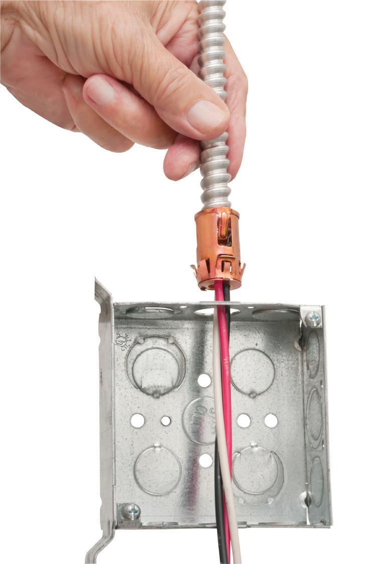
34 May 2024 • www.ecmweb.com
© MCA R&D Percent of Total 40% 20% 0% -20% -40% -60% -80% -100% -120%
1-13 weeks 13-25 weeks 25-50 weeks 50+ weeks Grand total
Percent change in baseline labor hour budget (BLHB) in JPAC® when change orders are recognized
Snap 2it® connectorS
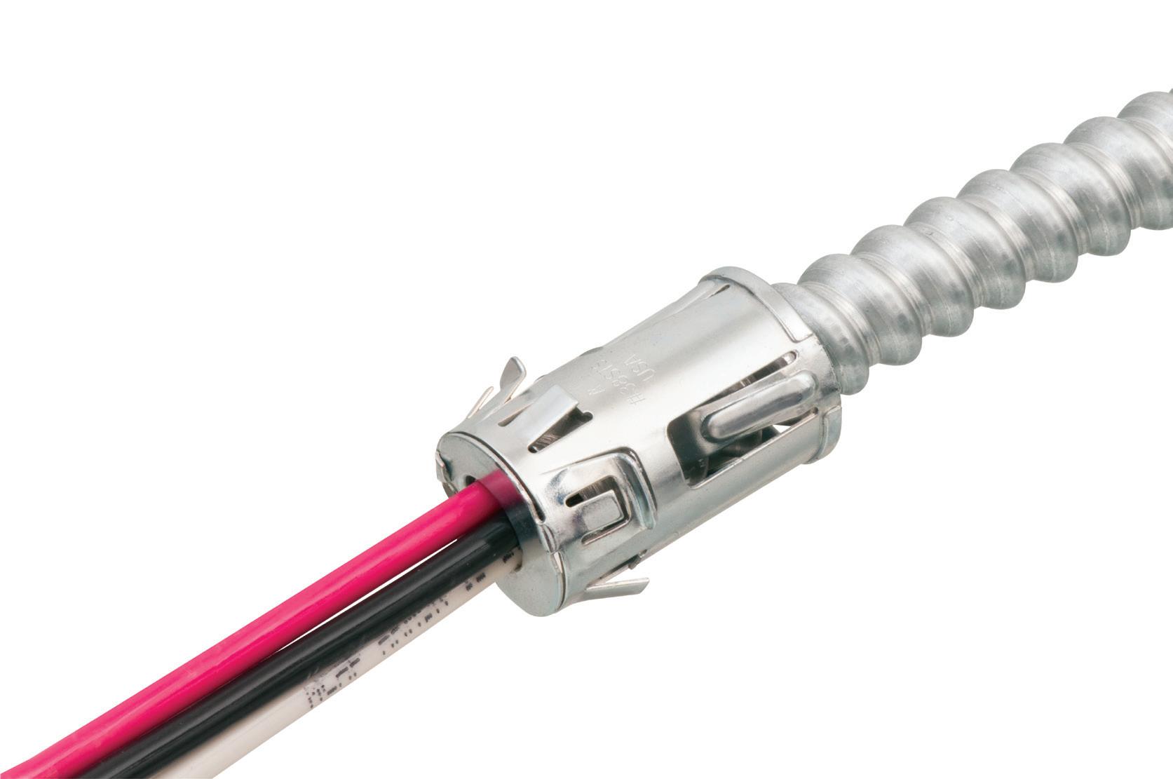
the cable into the connector and rotate the connector clockwise.
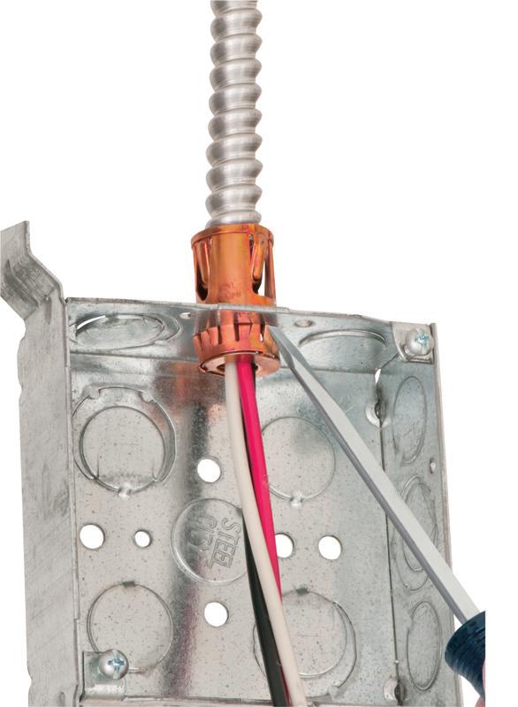
YEARS
Available in 3/8" trade size, both connectors install into a 1/2" knockout, and are Listed for steel and aluminum AC, HCF, MCI and MCI-A cable.
The tinted 40STS has more room inside for easier cable insertion.

for use with AC90 and ACG90 cable.
• Tested to UL 514B and Listed to meet UL ground fault requirements
• Removable Unscrew the connector counterclockwise to remove it from the cable. Remove the connector from the box using a flat blade screw driver. Release the snap tangs from the inside of the box while pulling the connector out of the knockout.
• Packed in heavy-duty, 200-piece boxes
CATALOG NUMBER CABLE RANGES STEEL Snap2It® connectors
38STSC AC, HCF, MCI, MC!-A 14/2 w ground, 14/3, 14/2 12/2 w ground, 12/3, 12/2 • 10/2 w ground, 10/3, 10/2 .405” Dia. Minimum to .605” Dia. Maximum
40STSC AC, HCF, MCI, MC!-A Tinted 12/2 w ground, 12/3, 12/2 • 10/2 w ground, 10/3, 10/2 .480” Dia. Minimum to .605” Dia. Maximum
5
7 INNOVATION
www.aifittings.com • 800/233-4717 Scranton, PA 18517 Product info aifittings.com/landing/38STS-40STS STEEL TINTED 40STSC 122 A of 38STSC OR 40STSC SNAP2IT Connectors! FREE COOLER
Why your answers could mean the difference between maintaining an electrically safe work environment and an electrical injury/fatality
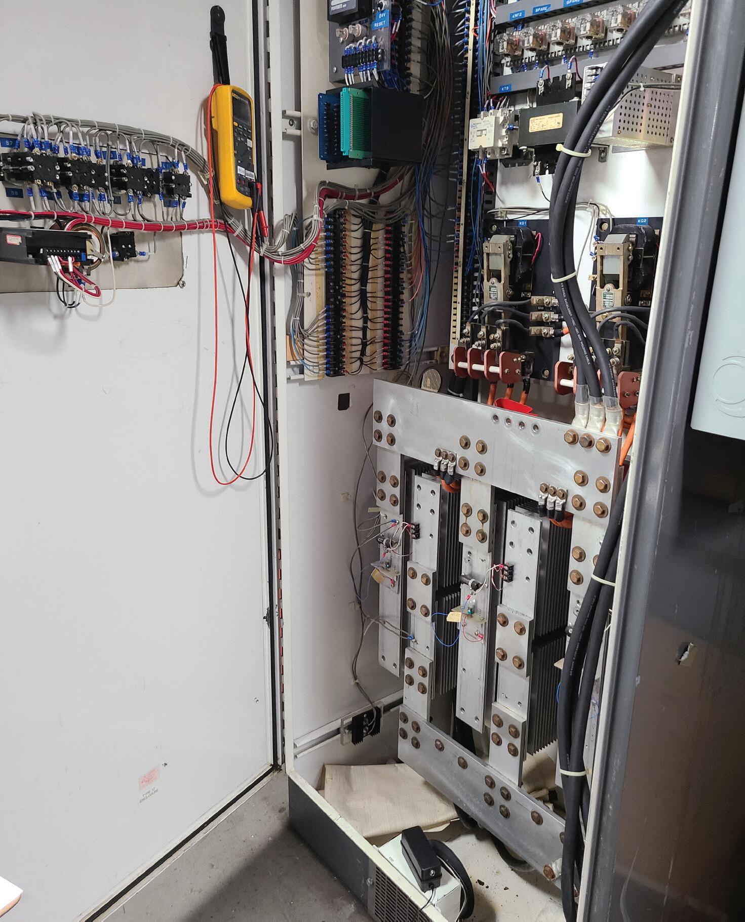
The most effective tool in electrical safety is knowledge — not only knowledge of the hazards but also knowledge of how to protect ourselves and others from those hazards. Throughout my career, I have had the pleasure of visiting many different locations/facilities and talking with electrical professionals about numerous electrical safety concerns. After all of these years, I still find it interesting just how many times electrical workers — all of whom come from various backgrounds, levels of experience, and job roles — continue to ask many of the same questions over and over. Following are a few of the common questions and answers per the current 2024 edition of NFPA 70E, Standard for Electrical Safety in the Workplace
Before jumping into the Q&A items, keep in mind that every task that could involve an electrical hazard, shock, or arc flash requires you to perform a risk assessment. The electric shock risk assessment requirements are covered in Sec. 130.4 of NFPA 70E, and the arc flash risk assessment requirements are covered in Sec. 130.5. An important habit every electrical worker should develop is to ask one important question immediately upon being assigned any new task: Will this task potentially involve exposure to an electrical hazard?
The goal for electrical workers is to perform all of their work on equipment that is in an electrically safe work condition as defined in Art. 120. However, keep in mind that sometimes the steps Exposed conductors
36 May 2024 • www.ecmweb.com
Tommy Northcott, Jacobs Technology, Inc.
By
require workers to wear appropriate electrical PPE unless they are in an electrically safe work condition.
required to establish an electrically safe work condition can involve potential electrical hazards. So let’s dive into the top 10 most common questions.
1. WHEN DO I HAVE TO WEAR VOLTAGE-RATED GLOVES?
Voltage-rated gloves (or insulating gloves) are required any time your hands — or anything you are holding (tools, test probes, etc.) — enter the restricted approach boundary of any exposed conductor rated at 50V or greater. The boundary size of the restricted approach boundary is directly related to the nominal voltage of the circuit or circuit part that is exposed. The distances for various voltages are found in Table 130.4(E)(a) for AC systems and Table 130.4(E)(b) for DC systems.
2. WHEN DO I HAVE TO WEAR ARC FLASH PPE?
Arc flash PPE is required any time you’re inside the arc flash boundary. Any part of the body that is inside this boundary must be protected. According to Sec. 130.5(E), the arc flash boundary is the distance at which the incident energy equals 1.2 cal/cm2. The boundary distance can either be calculated or determined by Table 130.7(C)(15)(a) or Table 130.7(C)(15)(b) when the requirements of those tables apply.
3. WHEN DO I NEED AN ENERGIZED ELECTRICAL WORK PERMIT (EEWP)?
Per Sec. 130.2, an energized electrical work permit (EEWP) is required when performing work within the restricted approach boundary of equipment that is not in an electrically safe work condition or when interacting with electrical equipment without any exposed circuits or circuit parts (but the task has an increased likelihood of injury from an arc flash event). An example of a task that could require an EEWP due to a potential increased likelihood of an arc flash event might be racking a breaker on/off an energized bus.
A critical aspect of electrical safety is the requirement that employers implement a policy that requires hazard elimination to be the priority in safetyrelated work practices [Sec. 110.2(A)].
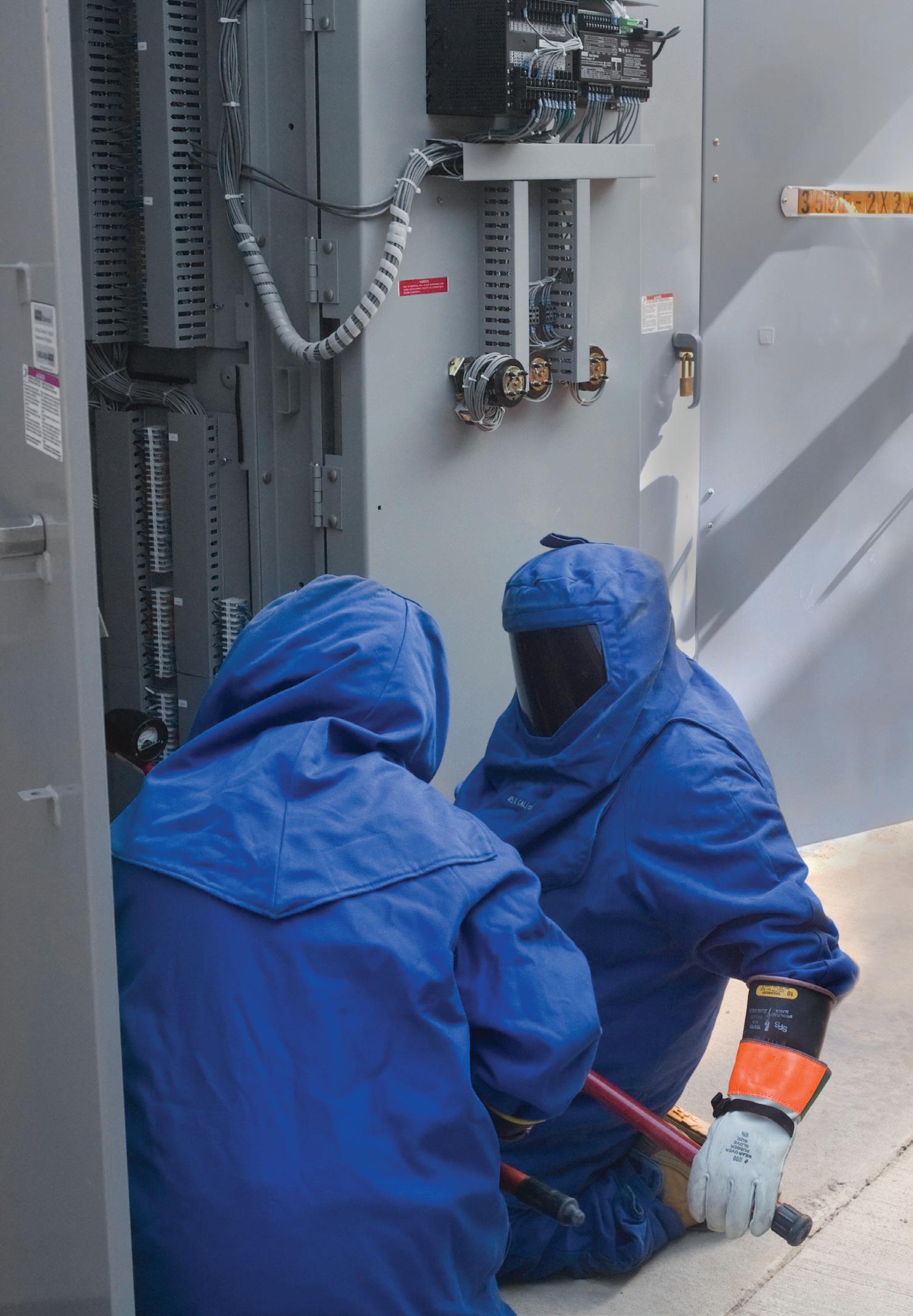
This hazard elimination is achieved through establishing an electrically safe work condition whenever it is feasible to do so (Art. 120).
There are eight steps to establishing an electrically safe work condition.
1. Determine all possible sources of electrical energy.
2. Open the disconnecting device(s) for those sources.
3. When possible, visually verify the disconnects are open.
4. Release any stored electrical energy.
5. Release or block any stored nonelectrical energy.
6. Apply lockout/tagout devices.
7. Verify the absence of voltage using the live-dead-live method.
8. Apply temporary protective grounds. When these eight steps are implemented, there is no electrical hazard exposure for the worker; therefore, an EEWP is not needed for the remaining tasks. Remember that the opening of disconnect devices and verifying the absence of voltage can involve electrical hazard exposure that would require personal protective equipment (PPE) to perform those tasks safely.
4. DO I NEED TO WEAR VOLTAGE-RATED GLOVES WHEN USING A DIGITAL MULTIMETER (DMM)?
The context of this question is typically related to 120VAC nominal circuits.
www.ecmweb.com • May 2024 37
Arc flash PPE is required any time work is being performed inside the arc flash boundary.
18915280 © Jaypetersen | Dreamstime.com
Photo
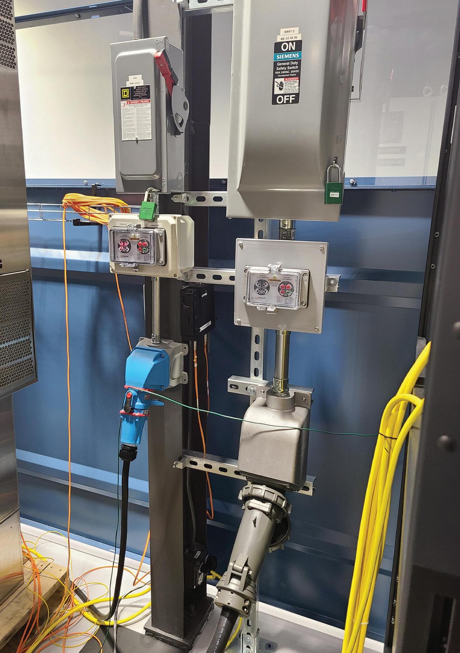
NFPA 70E defines “Working On (energized electrical conductors or circuit parts)” as “intentionally coming in contact with energized conductors or circuit parts with the hands, feet, or other body parts, with tools, probes, or with test equipment, regardless of the personal protective equipment (PPE) a person is wearing.”
NFPA 70E Sec. 130.4(G) states that any part of a qualified person’s body that crosses into the restricted approach boundary shall be insulated. Therefore, holding test probes that are in contact with the energized or potentially energized conductors is equivalent to contacting those energized conductors with your hands.
As per Sec. 130.7(C)(7)(a), “Employees shall wear rubber insulating gloves with protectors where there is a danger of hand injury from electric shock due to contact with energized electrical conductors or circuit parts.” If the qualified person’s hands, tools, probes, or test equipment cross into the restricted approach boundary of systems rated 50V or greater (AC or DC), then the use of voltage-rated gloves is required. This includes using a handheld meter to check voltages on 120VAC circuits.
5. IF THE ENCLOSURE DOORS
ARE CLOSED, WILL THIS PROTECT ME FROM AN ARC FLASH?
This question is becoming less common than it used to be, but I still run across workers who believe if the breaker enclosure door is closed there is no need for arc flash PPE when operating a breaker. The only time that it is safe to operate a circuit breaker with no arc flash PPE on is if the risk assessment verifies there is no arc flash hazard — or the equipment is arc-rated, installed, and operated per the manufacturer’s instructions. If the risk assessment verifies that there is an arc flash hazard potential, then the appropriate level of PPE must be worn to operate the breaker. Not only do the breaker enclosures have vents that will allow the super-heated air and gasses out of the enclosure, but arc flash events have also been shown to blow doors open, melt through metal barriers, and even strip bolts out of their holes to allow the pressure wave to escape — not to mention the common practice of only tightening enough of the latches/bolts to hold the enclosure/panel in place so that it is easier to remove on the next maintenance cycle, which is not an acceptable practice.
6.
DO I NEED ARC FLASH PPE IF I AM ONLY OPERATING ELECTRICAL EQUIPMENT?
This is very closely related to the last question. The difference is that the context of the previous question is someone who recognizes the potential for an arc flash hazard but has been led to believe that having the enclosure doors or panels closed will be able to contain the hazard. The context of this question usually relates to someone who doesn’t even really recognize the potential for an arc flash hazard. These are often operations personnel who are just simply turning 480VAC breakers on and off as part of their operations procedures. They aren’t opening any enclosures, exposing any conductors, or doing any maintenance, so they see this task as normal and not hazardous. However, as previously mentioned, the only time that it is safe to operate a circuit breaker with no arc flash PPE on is if the risk assessment verifies there is no arc flash hazard or the equipment is arc-rated, installed, and operated per the manufacturer’s instructions. If the risk assessment verifies that there is an arc flash hazard potential, then the appropriate level of PPE must be worn to operate the breaker.
38 May 2024 • www.ecmweb.com
Voltage indicators and test ports can provide a safe means for showing voltage is present or verifying the absence of voltage.
Plastic & Steel 8X10 TV BOX
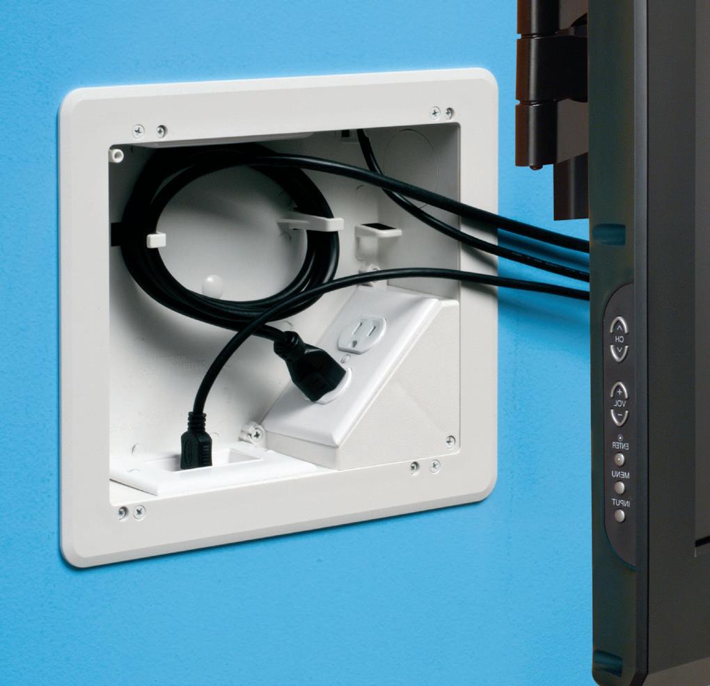
Arlington’s 8X10 TV Box™ with a Plastic or Steel Box offers the ultimate in versatility for installing TVs in new and retrofit projects. There's more room in the box for wires and it installs horizontally or vertically to properly position low voltage connections behind the TV.
• Ideal for home theater systems: multiple connections for sound systems, satellite TV, CATV, DVRs
• Brackets for neater cables, with a 1-1/2" knockout for ENT and other low voltage wiring
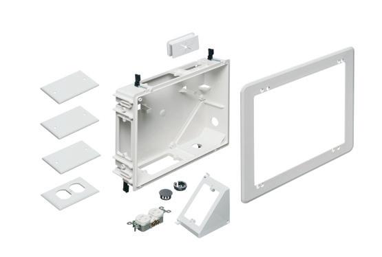
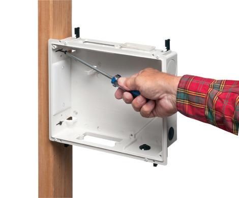
• Box mounts to stud in new work; for retrofit, mounting wing screws secure
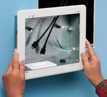


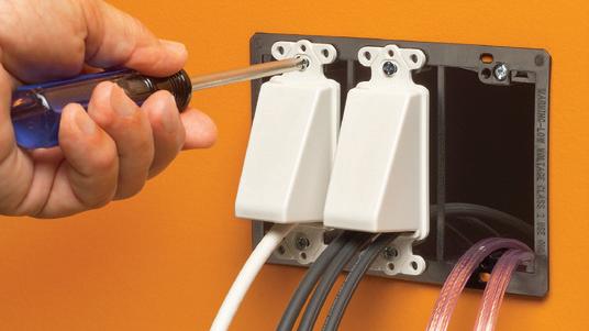
The SCOOP™ series of reversible, non-metallic ENTRANCE HOODS, PLATES AND DEVICES protect cable while delivering good looks and installation versatility. They also reduce labor and eliminate extra connections.
Our newest CABLE ENTRY DEVICES come with or without a wall plate for efficient cable management.
HOODS for decorator-style wall plates, single and two-gang PLATES install facing in or out...and save time!
• Low voltage cable protection
• Best way to run cable
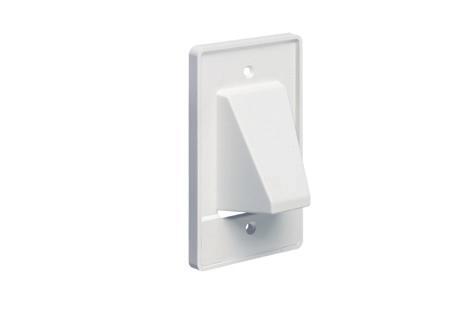
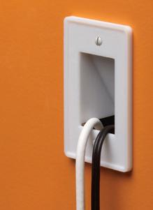

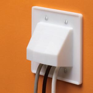

ARLINGTON 75YEARS TVBU810 PLASTIC TV BOX™ Ample space for multiple low voltage connections © 2012 REV0314 Arlington Industries, Inc 800/233-4717 • www.aifittings.com
Secure installation in RETROFIT PERFECT FOR HOME THEATER SYSTEMS VERTICAL OR HORIZONTAL • FOR RETROFIT & NEW WORK
TM Mounts to stud in NEW work Kit includes plastic or steel box, trim plate, duplex receptacle, line voltage box, wall plates, cable entry device, knockout plugs Product info aifittings.com/landing/TVBU810 97 TVBU810 w/ plastic box TVBS810 w steel box 11/14/23 11:05 AM THE SCOOP ENTRANCE PLATES, HOODS, DEVICES NON-METALLIC TM
CED130 entry device w slotted cover CED1 facing OUT CE2 facing OUT CER1 CE1 facing IN © 2009 REV 2015 Arlington Industries, Inc. Patented CED135 (with wall plate, order CED135WP) Arlington’s TVBU505 TV BOX Entry Device w Brush opening NEW 800/233-4717 • www.aifittings.com Product info aifittings.com/landing/scoop-series/ 19 2312ECM_Arlington_866400-1223_19.indd 1 11/14/23 11:16 AM
7. WHEN DO I NEED TO USE VOLTAGE-RATED TOOLS?
Voltage-rated tools are required to be used when working inside the restricted approach boundary of conductors that are not in an electrically safe work condition. Working inside the restricted approach boundary for non-diagnostic tasks also requires an EEWP. A task that would require voltage-rated tools also requires an EEWP, meaning that the worker should have an approved EEWP before performing any task that requires the use of voltage-rated tools. If the EEWP and hazard risk assessment process results in verifying that the task is infeasible to complete in an electrically safe work condition, then any work performed inside the restricted approach boundary requires tools that are properly rated and insulated to the correct nominal voltage.
8. IF EQUIPMENT HAS NO POWER COMING TO IT, IS IT SAFE TO WORK ON/AROUND EXPOSED CONDUCTORS WITH NO PPE?
This question is typically a result of a lack of understanding of what steps are required to make electrical equipment safe. It is common to think that if you are within line-of-sight of a disconnect switch — and the switch is in the “open” position — then it must be safe to work on the downstream circuits. However, the only thing known when seeing a disconnect switch with the handle in the open/off position is that the handle has been moved to the open/off position. There is no guarantee what happened inside that switch enclosure. There have been plenty of incidents of mechanical failure inside the switch enclosure that resulted in one or more phases remaining connected when the handle has been moved to the open position.
Even if you disregard the probability of a component failure, typically when you begin to work on a task, a certain level of tunnel vision comes into play as you focus on what you’re doing. Someone may come along and have a reason to close that disconnect switch not realizing that someone is working on downstream equipment. Since you are focused on the task at hand, you may not recognize their move to close the switch in time to stop them or get out of any
shock or arc flash boundaries before the circuit or circuit parts become energized. Just turning off the power does not make a circuit or circuit part safe.
The only approved means for establishing a scenario where no electrical PPE is required when interacting with circuits or circuit parts is to establish an electrically safe condition. It is essential that every electrical professional is proficient in this area. Review the answer in Question 3 to ensure you clearly understand the eight steps required in establishing an electrically safe work condition. Only after these steps have been taken can an exposed circuit or
circuit part be considered safe to work on or around without the need for electrical PPE.
9. WHEN ARE TWO QUALIFIED ELECTRICAL WORKERS REQUIRED TO COMPLETE A TASK?
There is no strict requirement in NFPA 70E for the use of a second qualified electrical worker to be present for specific tasks. However, the standard does require that a risk assessment be performed to identify potential exposure to electrical hazards. One of the required elements of the risk assessment is
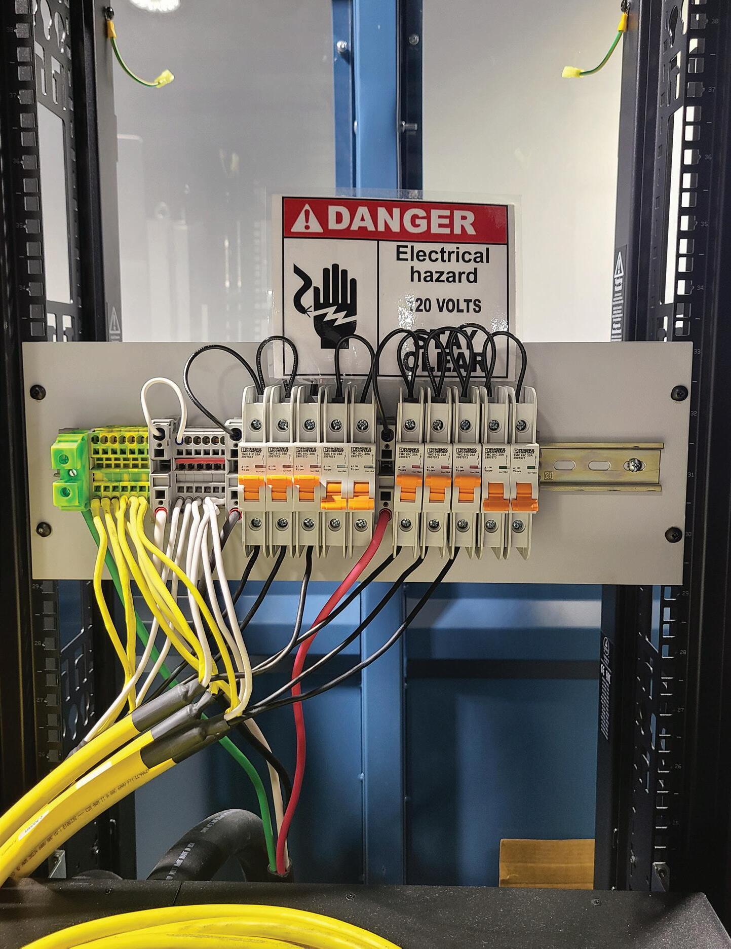
Even “finger-safe” designs can have exposed conductors if you do not have to remove anything to contact the conductor with a tool or test probe.
40 May 2024 • www.ecmweb.com
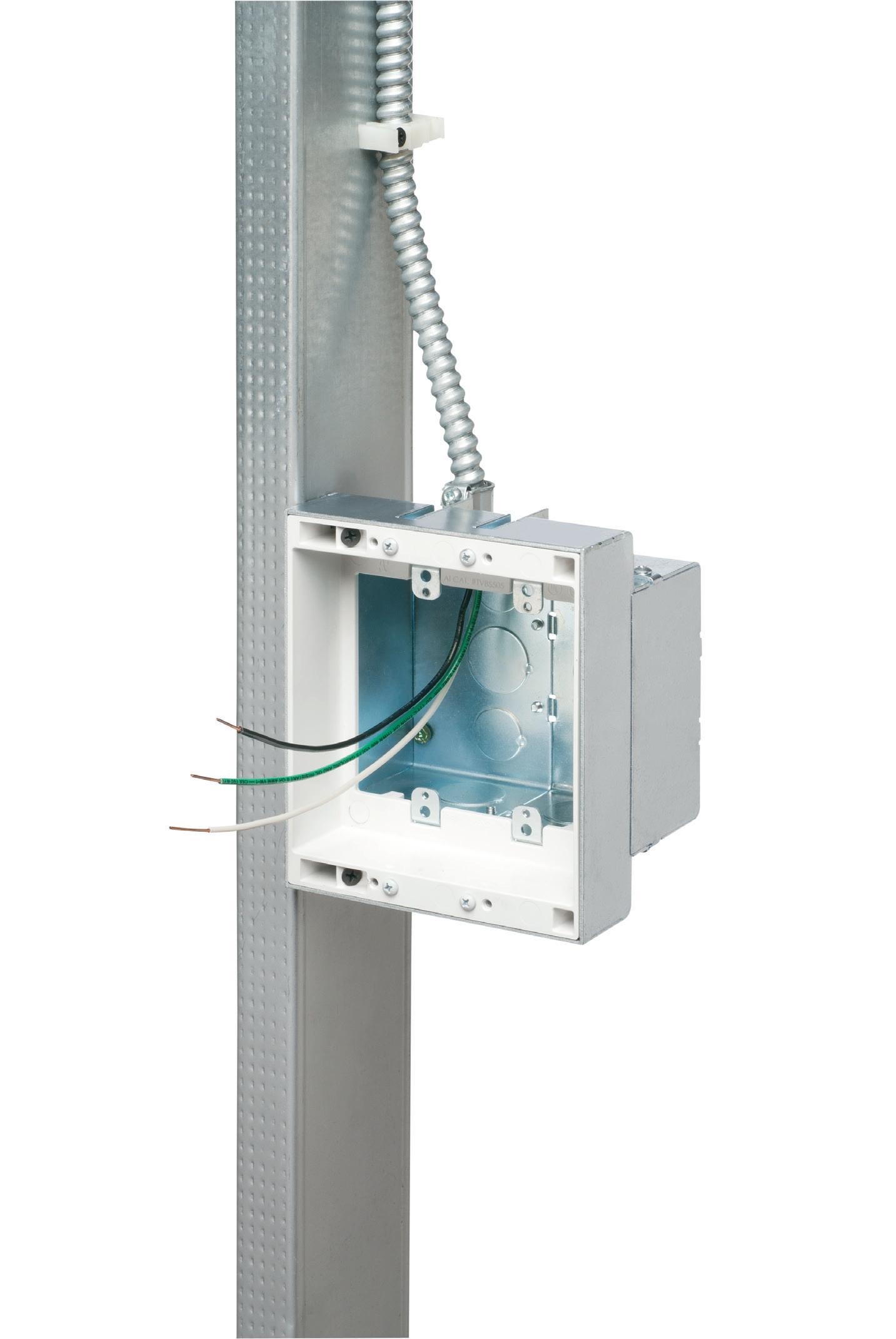
Arlington’s recessed STEEL combination power/low voltage TV BOX™ is the best way to mount an LED or Hi-Def TV flush against a wall.
TV BOX provides power and/or low voltage in one or more of the openings. Plugs and connectors stay inside the box, without extending past the wall.
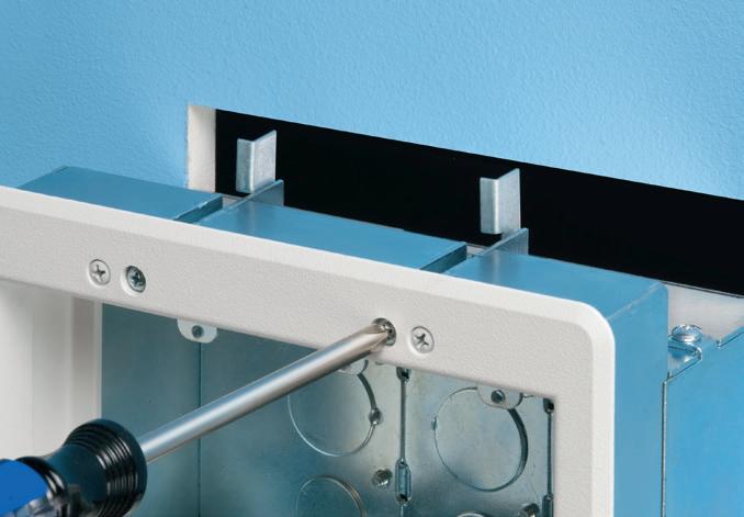
Designed for use in new or retrofit commercial construction where metal raceway is used, we have a STEEL TV BOX for almost any application!
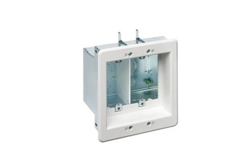


• Steel box; non-metallic paintable white trim plate
• Easy, secure installation
• Optional covers


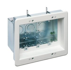

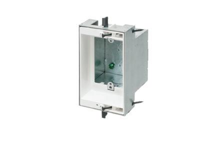
Arlington’s mounting brackets are the best way to install Class 2 wiring. They seat wall plates flush with the mounting surface and install fast!
Our new single gang, zinc mounting bracket, LV1M, for existing construction, offers extra rigidity so it won’t bend as easily as plastic. Plus, it has threaded holes for easy, fast device installation – and LABOR SAVINGS.
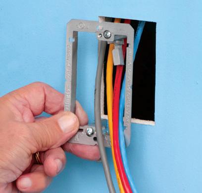
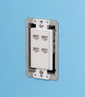
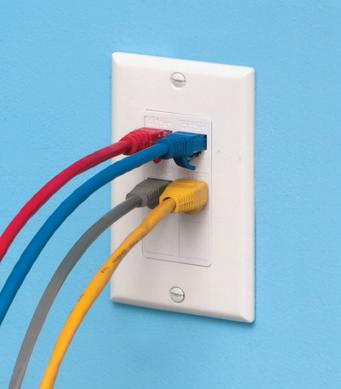

ARLINGTON
RECESSED FOR FLUSH-TO-THE-WALL MOUNTING OF LED, HI-DEF TVs COMBO BOXES FOR USE WITH METAL RACEWAYS STEEL
™KIT NEW! © 2008-2020 Arlington Industries, Inc. 2-GANG Mounting screws hold box on stud New work Mounting wing screws hold box in the wall retrofit 3-GANG TVBS507 p 800/233-4717 • www.aifittings.com Product Info aifittings.com/landing/recessed-tv-boxes Patented ! 1-GANG TVBS503 98 2312ECM_Arlington_866438-1223_98.indd 1 11/14/23 1:50 PM HEAVY-DUTY ZINC FOR CLASS 2 LOW VOLTAGE WIRING MOUNTING BRACKETS
TV BOX
Also available, a variety of single-, two-, three- and four-gang NON-METALLIC low voltage brackets,
others for specialty © 2023 Arlington Industries, Inc. COMMERCIAL EXTRA HEAVY Product Info aifittings.com/landing/lvm1 Patent pending 118 2312ECM_Arlington_866401-1223_118.indd 1 11/14/23 11:26 AM
and
implementing risk control per the hierarchy of risk control methods as found in Sec. 110.3(H). In an Informational Note following this requirement, the standard states “The risk assessment procedure could include identifying when a second person could be required and the training and equipment that person should have.”
It is often considered a best practice to require a minimum of two qualified electrical workers for any task that requires an EEWP as a minimum. The second qualified electrical worker not only can serve as an on-site first responder in the event of something going wrong, but, more importantly, they can also potentially help avoid something going wrong. Anyone who has worn arc flash PPE can attest to the fact that the PPE on some level limits visibility during the task. The second qualified electrical worker can be an additional set of eyes to help alert the first worker if their arms or other body parts or tools may be getting too close to energized conductors. The second qualified electrical worker is also another perspective that can engage in discussion on how to most effectively and safely accomplish the task.
10. CAN I LAYER TWO 20 CAL/CM2 SUITS TO ACHIEVE
40
CAL/CM2 PROTECTION?
Layering, concerning arc flash clothing ratings, is the idea of adding additional layers to increase the overall rating of the PPE as a whole. NFPA 70E uses the language of “layered system” or “clothing system” in the body of the standard. Informative Annex M, while not part of the requirements, provides some understanding of what is intended by using the word system in the context of layering. The Annex states, “Layering of arc-rated clothing is an effective approach to achieving the required arc rating when the layers have been tested together to determine the composite rating.” The only way to be certain that layers will increase the overall rating is if the layers were designed and tested to work together in a layered system. If a worker is wearing 8 cal/cm2 pants, an 8 cal/cm2 undershirt, and a 12 cal/ cm2 long-sleeve shirt (along with other required hand, foot, head, face, eye, and hearing protection), then the maximum arc flash energy the worker should be

potentially exposed to would be 8 cal/ cm2. The undershirt and long-sleeve shirt could not add up to 20 cal/cm2, and the exposure could not exceed 8 cal/cm2 because that is the maximum rating for which the whole body is protected due to the pants only being rated for 8 cal/cm2
IN SUMMARY
When it comes to electrical safety, two foundational principles can help us reach the safe work practices needed to protect ourselves and our coworkers. The first is that electrical workers should always prioritize only working on circuits or circuit parts that are in an electrically safe work condition. The second is that if creating an electrically safe work condition is infeasible, then any part of the body, tool, or test equipment that crosses a shock or arc
flash boundary must be insulated or protected from the potential hazard. Maintaining a focus on these two critical areas during the planning of all electrical tasks will significantly reduce the risk of worker exposure to electrical hazards and will help the worker reach the correct answer to any electrical safety-related questions.
Tommy Northcott is a professional engineer licensed in the state of Tennessee and a senior power engineer with Jacobs Technology, Inc., in Tullahoma, Tenn. He is also an NFPA 70E compliance subject matter expert, a principal member of the NFPA 70B Committee, electrical safety trainer, certified maintenance and reliability professional, and certified reliability leader. He can be reached at Thomas.Northcott@Jacobs.com.
42 May 2024 • www.ecmweb.com
The risk assessment should also include consideration of hazards/risks that may be caused by the required PPE, such as reduced dexterity or vision.
20518886 © Jaypetersen | Dreamstime.com
Photo
FAN/FIXTURE BOX
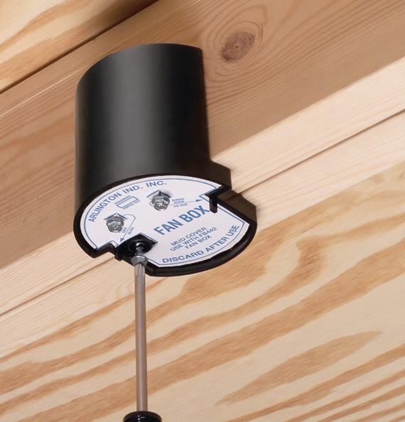
Super-secure installation!
Our lowest cost, L-shaped fan/fixture box mounts to single or double joists with a captive center screw. No loose parts!
screws ship captive, ready to install box and bracket.
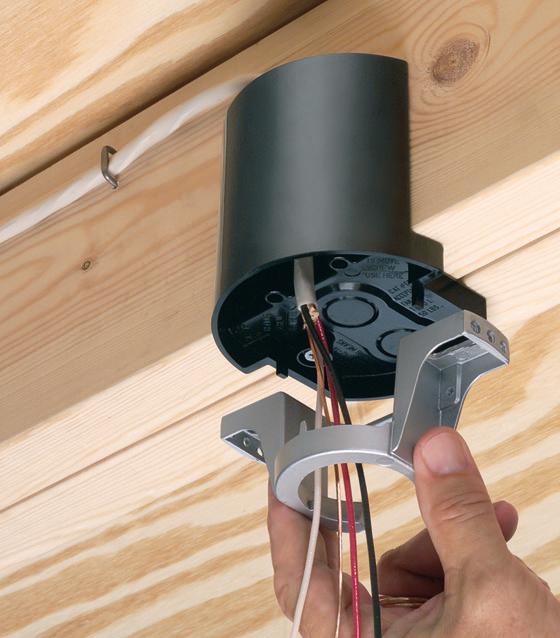


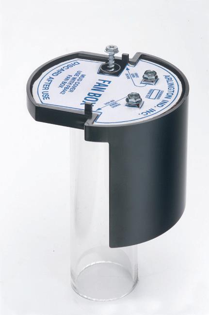
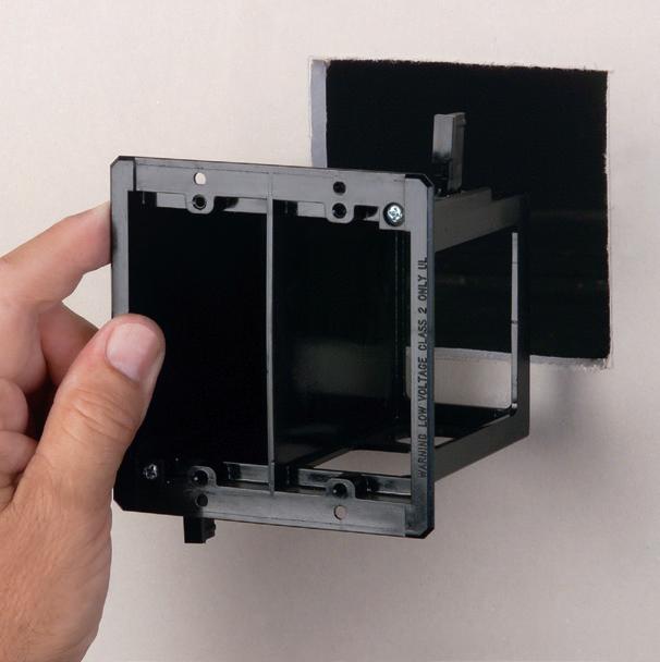
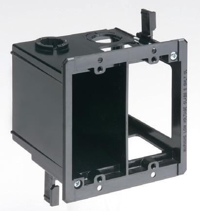
This convenient combo box has power and low voltage openings in the same box for a neat, time-saving installation.
The box adjusts to fit wall thicknesses from 1/4" to 1-1/2". Mounting wing screws hold it securely in place.
• 2-Hour Fire Rating
• Low voltage side has a combo 1/2" and 3/4" KO for raceway
• Includes NM cable connector (power side)
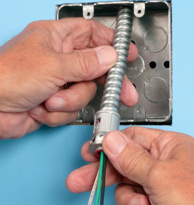
Arlington’s new one-piece RETROFIT SNAP2IT® fittings are easy to use in an OLD WORK installation, and handle the widest variety of cables! They’re ideal for adding additional circuits to a load center. And you get the same labor-savings in a retrofit installation!
Easy snap-in installation - NO TOOLS. Install connector into the knockout in an existing box, pulling cable/conduit through the knockout. Slip the fitting onto the cable, then snap the assembly into the box. That’s it... a secure installation with no pullout
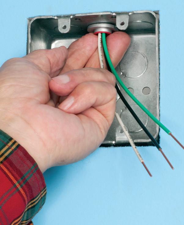
Widest total cable ranges 14/2 to 10/3
Widest variety of cables AC, MC, HCF, MC continuous corrugated aluminum cable, MCI-A cables (steel and aluminum), AC90,
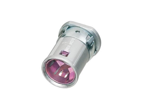

ARLINGTON 75YEARS
Snap connector onto installed MC cable.
Snap assembly into box. Done! 38RAST Patented NO TOOLS • EASY SNAP-IN INSTALLATION • SAVES TIME! FOR RETROFIT INSTALLATIONS SNAP2IT® CONNECTORS © 2014 Arlington Industries, Inc. NEW! 800/233-4717 • www.aifittings.com 8 Product info aifittings.com/landing/38rast-40rast/ 2312ECM_Arlington_866444-1223_8.indd 1 11/14/23 2:25 PM LVDR2
Patented Installed NM cable connector COMBO BOX FOR RETROFIT PROJECTS POWER & LOW VOLTAGE © 2013 Arlington Industries, Inc. 800/233-4717 • www.aifittings.com Product info aifittings.com/ landing/ combo-boxes 84 2312ECM_Arlington_866407-1223_84.indd 1 11/14/23 10:48
SECURE MOUNTING TO SINGLE, DOUBLE JOISTS © 2001-2016 Arlington Industries, Inc. LOWEST COST • L-SHAPED
For 1/2" or 5/8" drywall Fast, easy installation • Locator posts assure proper positioning of fan/fixture bracket • 2-hour Fire Rating FB442 13.4 cu. inch UL rated fans up to 70 lbs; fixtures to 200 lbs. 800/233-4717 • www.aifittings.com Product info aifittings.com/landing/joist-mount-fan-fixture-box 36 2402ECM_Arlington_902126-0224_36.indd 1 1/23/24 4:34 PM
Now that NFPA 70B has been elevated to a standard, it’s critical to understand how all of the electrical standards should work together.
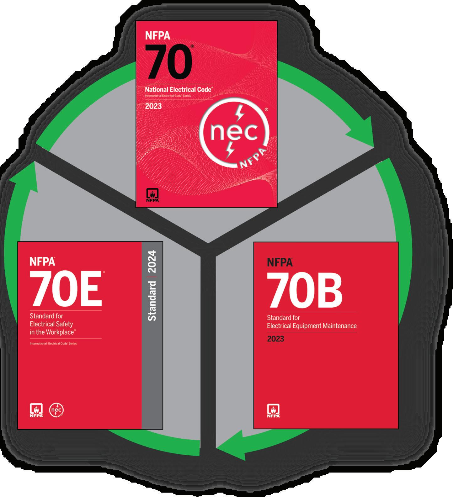 By Chuck Fox, CESCP, The Electrician, Inc.
In managing any electrical system, the National Fire Protection Association (NFPA) publishes three related documents (NFPA 70, National Electrical Code; NFPA 70E, Standard for Electrical Safety in the Workplace; and NFPA 70B, Standard for Electrical Equipment Maintenance) that designers, installers, and maintenance professionals need to base their work on. As of January 2023, NFPA 70B has evolved from a “recommended practice” into an enforceable standard. With this elevation of NFPA 70B, electrical professionals (including facility
44 May 2024 • www.ecmweb.com
FAN FIXTURE BOX

Captive screws attach bracket ends to joists

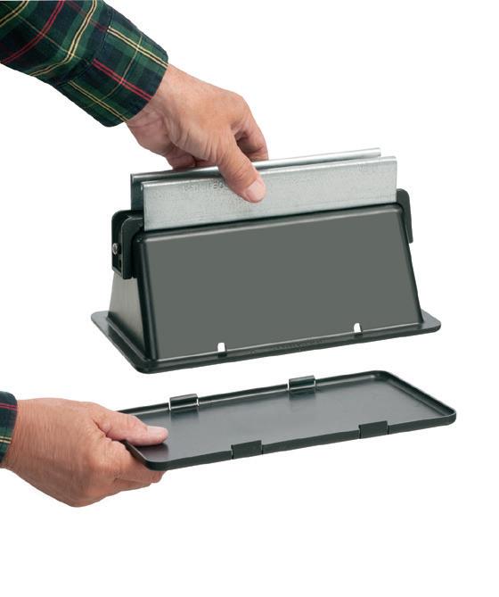
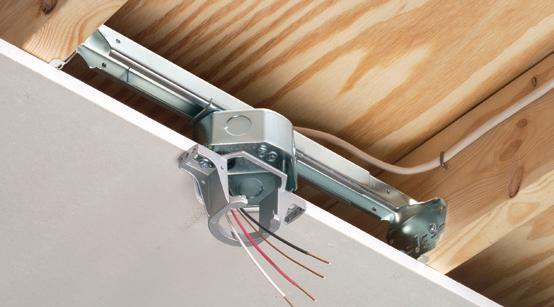
Arlington’s heavy-duty, plated steel fan/ fixture box has an adjustable bracket that mounts securely between joists spaced 16" to 24" o.c.
Flush ceiling installations

FBRS415 is designed for ceilings up to 1-1/4" thick. For 1/2" ceilings, use the pre-bent positioning tab. For other ceiling thicknesses, bend along the appropriate score line.
• 15.6 cu. inch box ships with captive screws, mud cover, installed NM cable connector
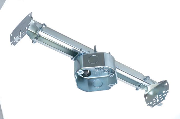


ROOF TOPPER® supports raise conduit/raceway 4" or more off the roof surface, allowing contractors to comply with the 2017 NEC® for temperature adjustment for circular conduit.
The heavy-duty base, made of 100% recycled material, sits on the roof deck. There’s no need to mount ROOF TOPPER to the surface with mechanical fasteners.


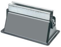
Offered in a variety of sizes and configurations, ROOF TOPPER supports up to 2000 lbs, and stands up to extreme rooftop conditions protecting and elevating conduit or raceway above the roof deck.

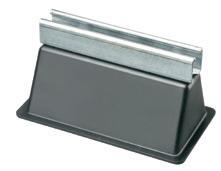


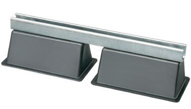
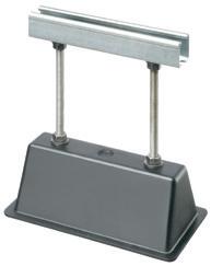

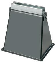
ARLINGTON 75YEARS
box position © 2004-2013 Arlington Industries, Inc.
Attach to joists, adjust
ADJUSTABLE BRACKET • FOR NEW CONSTRUCTION FLUSH CEILING INSTALLATIONS
Positions box between joists Fan bracket installation screws Captive screws from both sides attach bracket ends to joists Positioning tab for 1/2" ceilings FBRS415 Patented Product info aifittings.com/landing/fbrs415 UL ratings 70 lb fan/90 lb fixture at 24" oc 70 lb fan/150 lb fixture at 16" oc CSA
16"
24" 41 800/233-4717 • www.aifittings.com 2312ECM_Arlington_866406-1223_41.indd 1 11/14/23 12:19 PM
rated 50 lb fan/fixture at
and
Patented 5-5/8" H RTS4 9" wide RTS421 12" H RTS12 9" w 21" w RTSE405 5" w RTSE1209 9" w x 12" h RTSE409 9" w STRUT ATTACHED w END CLAMPS 5-5/8" H © 2011-2015 Arlington Industries, Inc. UV RESISTANT • 100% RECYCLED MATERIAL RELIABLE ROOFTOP SUPPORT OF CONDUIT, CABLE TRAY Raceway raised 12" above the roof Ra 12 t RTS4 800/233-4717 • www.aifittings.com Product info aifittings.com/landing/rooftopper NEW R OOF TOPPER ® SLED STYLES 114 2312ECM_Arlington_866443-1223_114.indd 1 11/14/23 2:57 PM
and maintenance managers) now have some well-developed guidelines to keep people safe while ensuring a strong and reliable electrical system. With these guidelines, however, come some potential compliance challenges.
A combined study of these publications (their current and past editions) allows us to identify the trend to emphasize and develop standards for the safety-related maintenance of electrical equipment. Let’s take a closer look.
HISTORICAL HIGHLIGHTS
Looking back, the 2009 edition of NFPA 70E was the first edition to specify a compliance requirement for device-specific equipment labeling. As per 70E 2009 Sec. 130.3(C), “Equipment Labeling. Equipment shall be field-marked with a label containing the available incident energy or required level of PPE.”
Of course, to mark equipment in the field, an arc flash study was required. Within this same 2009 edition, the reference calling for the arc flash study contained the only reference to “condition of maintenance.” As per NFPA 70E 2009 Sec. 130.3, “The arc flash hazard analysis shall take into consideration the design of the overcurrent protective device and its opening time, including its condition of maintenance.”
The 2009 edition of NFPA 70E, Chapter 2, does reference safety-related maintenance but also includes text to narrow the focus to “only maintenance directly associated with employee safety” [Sec. 200.1(1)]. Specific elements of what is now defined in NFPA 70B, the Electrical Maintenance Program, were not yet part of the standard so without specific condition of maintenance requirements, many arc flash studies focused on the nameplate data of equipment required to calculate an arc flash label. Condition of maintenance elements were not included at this time nor were requirements for an electrical maintenance program beyond the arc flash study.
The 2015 edition of NFPA 70E was a major step forward in developing at least an awareness/need for a safetyrelated maintenance program. The scope of NFPA 70E was expanded to recognize that a component of employee safety begins with electrical equipment maintenance. The text expanded electric safety to now reference “safety-related maintenance and other administrative
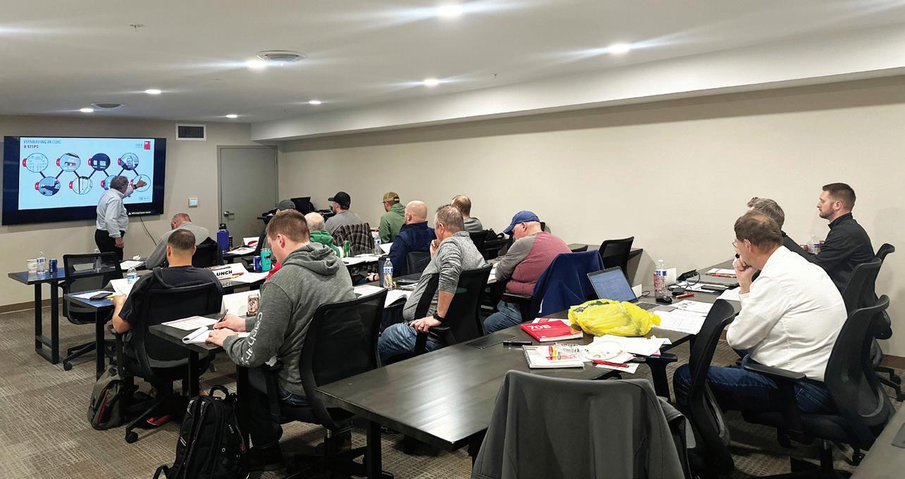
Electrical professionals must study current and past editions of all electrical standards in order to maximize safety-related maintenance of electrical equipment. Therefore, training is a critical component to success.
controls” [NFPA 70E 2015 Sec. 90.2, Scope]. Additionally, this new compliance requirement was further described by this new entry in the electrical safety plan. As per NFPA 70E 2015 Sec. 110.1(B) Maintenance, “The electrical safety program shall include elements that consider condition of maintenance of electrical equipment and systems.”
The 2018 edition of NFPA 70E added equipment inspections as a new element of the electrical safety program. “The electrical safety program shall include elements to verify that newly installed or modified electrical equipment or systems have been inspected to comply with applicable installation codes and standards prior to being placed into service” [Sec. 110.5(B) Inspections]. While the scope of this inspection requirement focused on newly installed equipment, a well-developed electrical maintenance program should include a systematic inspection schedule for the site’s total inventory. For the first time, the 2018 standard also added a definition for maintenance. “Maintenance – Condition of” is the state of the electrical equipment considering the manufacturers’ instructions, manufacturers’ recommendations, and applicable industry codes, standards, and recommended practices [NFPA 70E 2018 Art.100 Definition]. But perhaps the compliance requirement with the most impact in NFPA 70E 2018 was Sec. 105.3 Responsibility, which placed a much stronger call to action to develop a written electrical safety program. The basic outline of the Electrical Safety Program (ESP) was outlined in Sec.
110.1. Efforts to develop the electrical safety plan included a broader capture of safety-related maintenance require ments throughout the 70E document.
The 2021 and 2024 editions of NFPA 70E did not define any new requirements of safety-related maintenance, but the important changes to the NFPA 70B pub lication were soon to be launched. NFPA 70E 2024 added Informative Annex S –Assessing the Condition of Maintenance. But remember, the descriptions provided in an Annex are noted as “Informational Only” and do not create direct compli ance requirements. Most frequently, an Annex will provide additional details and approaches that contribute to compliance.
CROSS REFERENCE RESOURCES
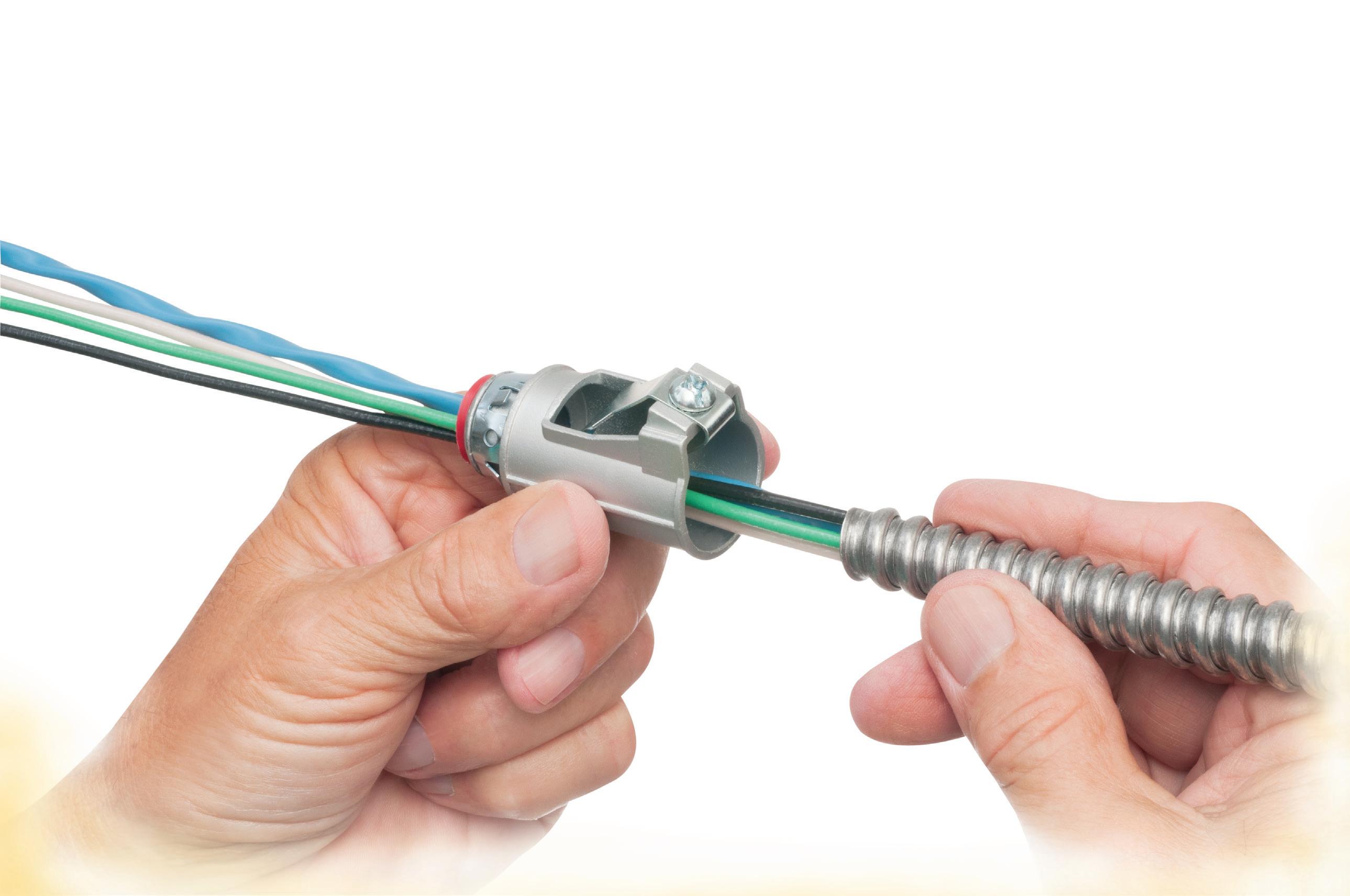
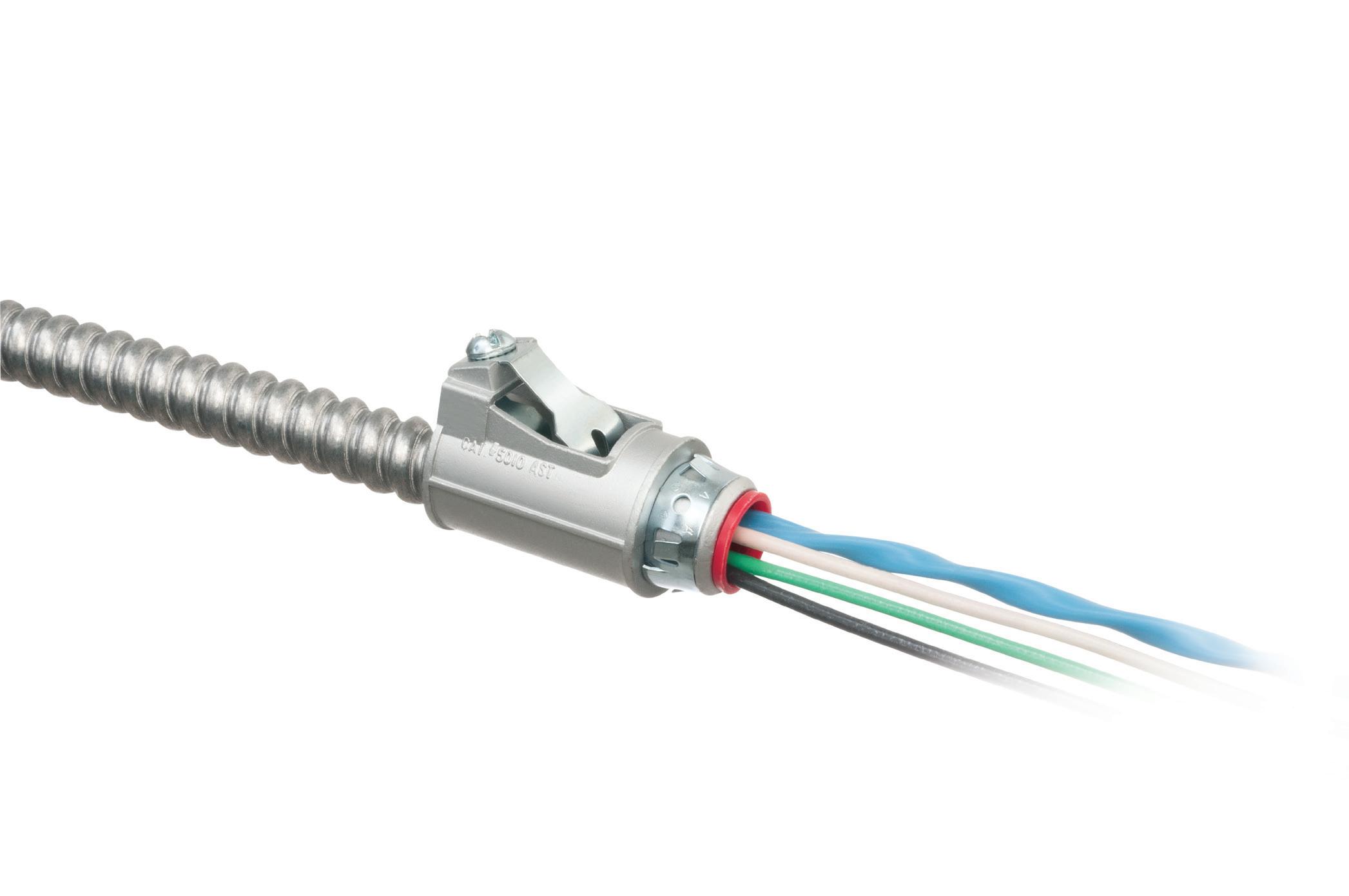
The references described thus far com prise a trend to evolve the metrics of electrical equipment maintenance as one of the foundational elements of employee safety and equipment safety. For further emphasis, many compliance topics are addressed in both the NFPA 70E and NFPA 70B standards as listed in the Table below. NFPA 70E 2024 includes the Electrical Safety Program, and NFPA 70B 2023 outlines the Electrical Maintenance Program requirements. Key objectives of the Electrical Maintenance Program include:
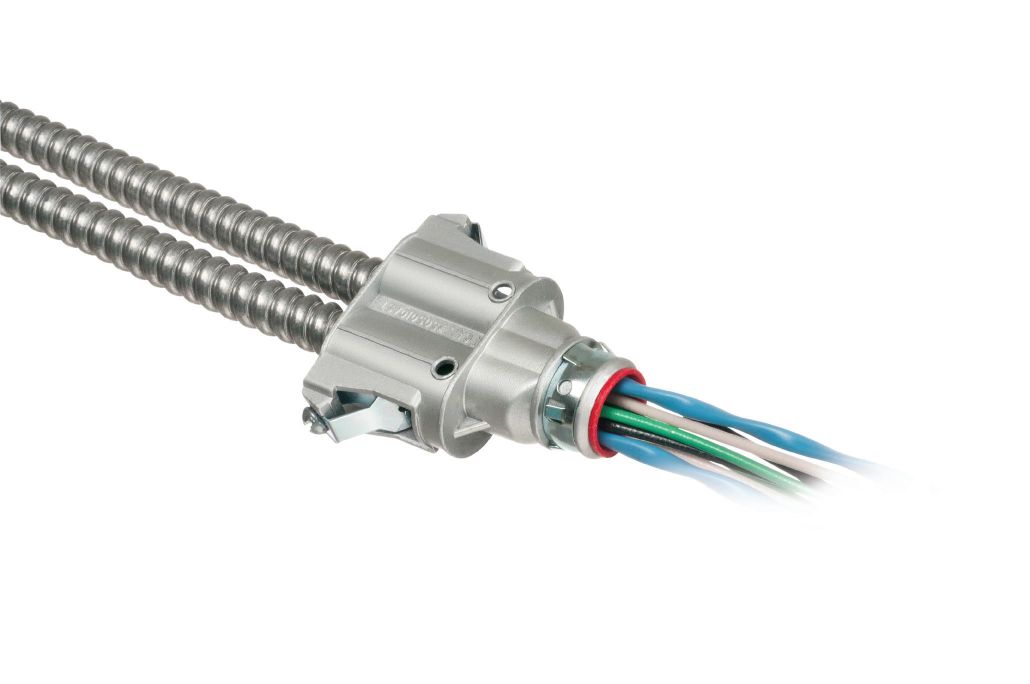
• Preventing equipment failures that can also cause injury to employees.
• Establishing a program for compliance with NFPA 70E and now NFPA 70B standards
• Increasing the lifespan of equipment with ongoing maintenance processes
46 May 2024 • www.ecmweb.com
Fully assembled, SNAP2IT® fittings handle the widest variety of MC cable AND THE NEW MC-PCS cables.
Compared to fittings with a locknut and screw, you can’t beat these snap in connectors for time-savings!


LISTED SNAP2IT ® CONNECTORS FOR NEW MC-PCS CABLE ...lighting & low voltage circuits in the same cable


• Fits widest range and variety of MC cable 14/2 to 3/3
AC, MC, HCF, MC continuous corrugated aluminum cable and MCI-A cables (steel and aluminum)...including the new MC-PCS cable that combines power and low voltage in the same MC cable
ANY Snap2It Connectors LISTED for MC cable are also LISTED for MC-PCS cable! These products offer the greatest time-savings.
• Fast, secure snap-on installation
• Easy to remove, reusable connector From cable Loosen screw on top. Remove connector from cable. From box Slip screwdriver under notch in Snap-Tite® Remove connector.
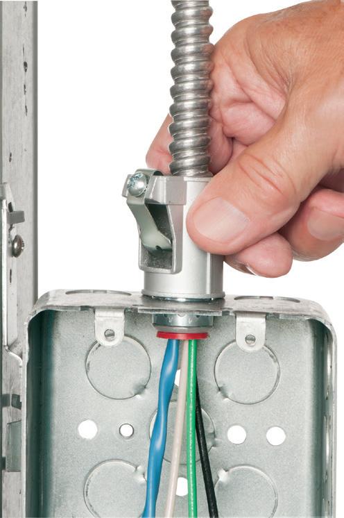
17 S
www.aifittings.com • Scranton, PA 18517 • 800/233-4717 © 2015 Arlington Industries, Inc. 4010AST 1/2” KO CATALOG DESCRIPTION NUMBER Snap2It® connectors OUTSIDE DIA (OD) 4010AST Snap in, 1/2" KO w insulated throat 5010AST Snap in, 1/2" KO w insulated throat 505010AST Duplex Snap in, 3/4" KO w insulated throat (2) .590 to .820 4110ST Snap in, 1/2" KO 414110ST Duplex Snap in, 1/2" KO (2) .525 to .640 4141107ST Duplex Snap in, 3/4" KO (2) .525 to .690
SNAP2IT® CONNECTORS
Easy to Snap into Box!
4141107ST Patented. Other patents pending. 9 Product info aifittings.com/landing/snap2it-mc-cable-connectors
This table represents Articles where the compliance topic is referenced in both NFPA 70E and 70B.
The general structure of the Electrical Maintenance Program and the Electrical Safety Program will include the following elements:
• Develop an electrical system device inventory.
• Complete a visual inspection and other tests to develop a baseline condition of maintenance.
• Complete an overall risk assessment.
• Develop a plan for electrical equipment maintenance.
• Document the maintenance tasking when completed.
• Audit the electrical maintenance program.
ELECTRICAL SYSTEM INVENTORY
When establishing an Electrical Maintenance Program, a detailed baseline inventory of the electrical components must first be developed. There can be significant latitude in how this device inventory is collected. For example, is a motor control center (MCC) line-up referenced as “one device,” or is each vertical section and each motor control “bucket” profiled separately? A best practice is to be as detailed as needed to properly document a one-line diagram and establish an incident energy/short circuit/and coordination result for each component.
VISUAL INSPECTION AND OTHER TESTS TO ASSESS THE CONDITION OF MAINTENANCE
As the electrical device profiles are being developed, the protocols of a full visual inspection as well as other condition of maintenance assessment can be completed concurrently. The result can be a problem report of all visual inspection issues and other test results, such as identified infrared problems. A best practice of the Electrical Maintenance Program is to implement the work sessions (frequently building or area-wide maintenance shutdowns) to complete repairs and document the resolution of the reported problems.
ADDITIONAL RISK ASSESSMENT BASED ON REQUIRED ENGINEERING STUDIES
Based on the data presented, NFPA 70B outlines the specific assessments of a short-circuit audit, a device coordination assessment, and the incident energy (arc flash) results. While
these elements have generally been included with a comprehensive arc flash risk assessment, NFPA 70E does not have a specific requirement for these electrical system risk factors. For example, NFPA 70E 2024, Sec. 210.6 [Protective Devices] states that “protective devices shall be maintained to adequately withstand or interrupt available fault current.” There is no specific compliance text that requires a short-circuit study. The EPM program requirements of NFPA 70B now fully describe this compliance challenge. See NFPA 70B Sec. 6.3 [Short Circuit Studies].
Based upon arc flash incident energy data, what should be considered for incident energy reduction? Based on NFPA 70E Sec. 110.2(A)(1) [Electrically Safety Work Condition], “Hazard elimination to be the first priority in the implementation of safety-related work practices. It remains the responsibility of management to determine what is a significant hazard and is the investment in its resolution a reasonable cost.”
GETTING STARTED
Develop a plan for the frequency and content of maintenance procedures. NFPA 70B 2023 Chapter 9 presents an entire assessment protocol for establishing the frequency of recommended maintenance intervals. NFPA 70E Sec. 200.1(2) says “it is left to the employer to choose from the various maintenance methods available to satisfy the requirements of this (70E) Chapter 2.” This is an additional example of the more detailed Electrical Maintenance Program guidelines that in recent editions have created the additional emphasis safety related maintenance compared to the more generic descriptions of prior editions.
DOCUMENT THE TEST AND INSPECTION RESULTS
If it is not documented, it did not happen. The proper documentation of electrical maintenance protocols is critical to the overall management of the Electrical Maintenance Program. What has been tested and what was bypassed within a maintenance cycle assures a well-managed program of electrical equipment maintenance and safety.
AUDIT
Audit the Electrical Maintenance Program to ensure maintenance activities remain on schedule/plan. The audit should also include a review of future editions of the NFPA standards to identify new compliance requirements.
CONCLUSION
The Electrical Maintenance Program can be viewed as a segment or chapter of the overall Electrical Safety Plan. Employee training, overall risk assessment, and definition of maintenance or troubleshooting procedures are also topics shared between the Electrical Maintenance Program and the Electrical Safety Plan. Safety related maintenance practices are now identified and recognized to be an essential elements of electrical system management. Employee safety is enhanced by reducing the risk of equipment failure along with the additional benefits of electrical
reliability.
Chuck Fox is the general manager, emeritus of the Electrical Testing Services division of The Electrician, Inc. He’s been an NFPA Certified Electrical Safety Compliance Professional since 2014. He can be reached at ChuckF@theelectricianinc.com.
48 May 2024 • www.ecmweb.com
system
Topic NFPA 70E 2024 NFPA 70B 2023 Inspection Sec. 110.3(B) Sec. 4.2.2 Condition of maintenance Sec. 110.3(C) Sec. 4.2.3 Program principles Sec. 110.3(E) Sec. 4.2.4 Program controls Sec. 110.3(F) Sec. 4.2.5 Incident investigations Sec. 110.3(J) Sec. 4.2.6 Program audit Sec. 110.3(K) Sec. 4.2.7 Qualified individual Sec. 110.4 Sec. 5.1.1 Single-line diagrams Sec. 205.3 Sec. 6.2 Incident energy study Sec. 130.5 Sec. 6.7 Short-circuit study Sec. 210.6 Sec. 6.3 Coordination study See NFPA 70 - NEC Sec. 6.4
Arlington’s new duplex diecast couplings save time and easy transitions from 3/4" EMT to 3/8" trade size flexible metal cables – perfect for running MC cable above a drop ceiling and connecting EMT to feed a box or switch.
combination couplings install easily on AC, MCI-A, HCF steel and aluminum cable, flexible metal conduit (steel and aluminum, regular and reduced wall), MCI cable and continuous corrugated aluminum. And offer independent securing of different size cables.
• Tested, LISTED to exceed UL ground fault requirements Compatible with 3/4" EMT
SADDLE GRIP® styles
aifittings.com/landing/zinc-combination-couplings
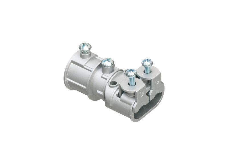
Save time and money! Arlington’s low cost MC cable fittings, for dry locations only, are super-convenient and cost-effective. End stop bushings vary the size of the opening so ONE trade size fits several cable sizes!
Changing end stop bushings is fast and easy. No need to remove the strap. Insert the bushing that works the best with the cables you’re installing.
Reduce inventory –Costs much less than steel and malleable iron fittings Built-in end stop
* Examples of 3- and 4-conductor cables accommodated.
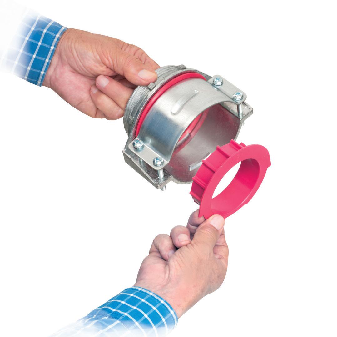
ARLINGTON 75YEARS THAT FIT SEVERAL CABLE SIZES MC
FITTINGS 8412 1" .780 1.120 .660 1.000 6/3, 6/4, 4-3, 4-4, 2-3, 2-4, 1-3 8413 1-1/4" 1.000 1.460 .870 1.370 2-3, 2-4, 1-3, 1-4, 1/0-3, 1/0-4, 2/0-3, 2/0-4, 3/0-3 8414 1-1/2" 1.360 1.770 1.250 1.590 2/0-4, 3/0-3, 3/0-4, 4/0-3, 4/0-4, 250-3, 250-4 8415 2" 1.700 2.200 1.550 2.050 250-4, 300-4, 350-3, 350-4, 500-3 8416 2-1/2" 2.100 2.700 1.950 2.400 500-3, 500-4, 600-3, 600-4, 750-3 8417 3" 2.500 3.300 2.350 3.000 600-4, 750-3, 750-4 8418 3-1/2" 3.300 3.600 3.031 3.500 750-3, 750-4, 1000-4
CABLE
NEW SIZE! 3-1/2" 800/233-4717 www.aifittings.com NEW 3-1/2" 8418 8418 for 1000 Mcm wire and TECK90 © 2008 REV0221 Arlington 14 Product info aifittings.com/landing/8412 2312ECM_Arlington_866402-1223_14.indd 1 11/14/23 11:34 AM
TRANSITION from EMT to FLEXIBLE METAL CABLE... THE EASY WAY! Patent pending Saddle Grip® 8675 SNAP2IT® 3/4" EMT 8675SG NEW 88 2312ECM_Arlington_866431-1223_88.indd 1 11/14/23 1:13 PM
COUPLINGS
Lack of formal training reveals gaps in competency among electrical professionals when working on new electrical power distribution equipment, especially racking out or in low- or high-voltage power circuit breakers.
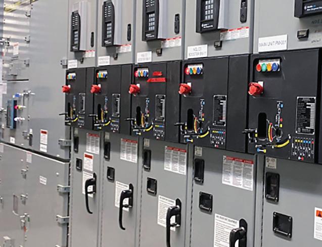
Electrical maintenance professionals must be familiar with and understand the operational aspects of many types of equipment, such as this high-voltage arc-resistant switchgear and motor starter mimic display.
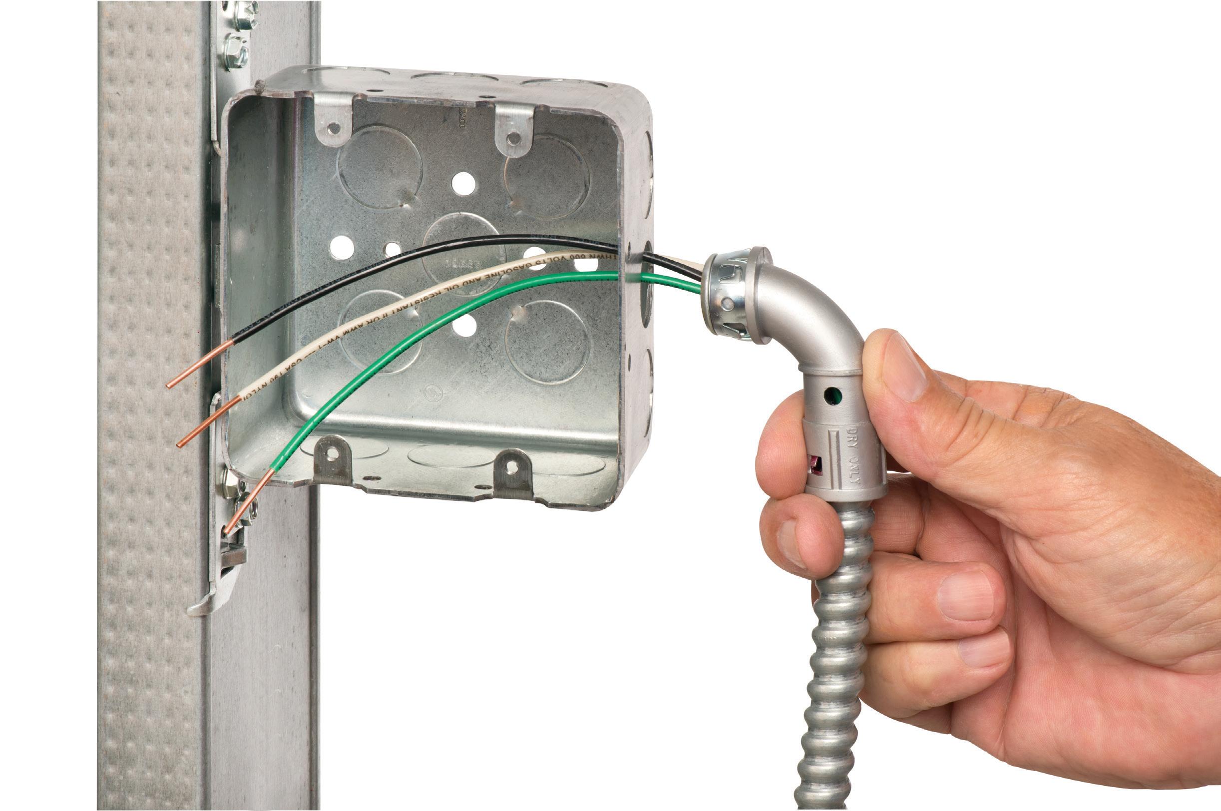 By Terry Becker, P.Eng., TW Becker Electrical Safety Consulting, Inc.
Racking in or out a power circuit breaker is simple, right? Although this task sounds pretty straightforward in theory, that’s not always the case. In fact, during years of field work related to external electrical safety audits or while completing practical hands-on electrical safety program training in my electrical safety consulting practice, in general, I have found a lack of adequate formal training for “qualified persons” with new or updated electrical equipment technology related to power distribution electrical equipment. Specifically, when capital project teams had successfully procured both low- and high-voltage arc-resistant electrical equipment, no formal training was typically provided. Where low- and high-voltage switchgear power circuit breakers had been provided, there was a lack of awareness of updated design elements related to manual racking or onboard remote racking (i.e., emergency extraction). Lastly, related to new high-voltage arc-resistant electrical equipment (i.e., switchgear) with embedded high-voltage motor starters, there was a lack of awareness of arc-resistant electrical equipment/type (e.g., IEEE C37.20.7
50 May 2024 • www.ecmweb.com
(SEE ABOVE)
• Easy snap-in cable installation Save time over 90° 2-screw MC Connectors at same cost per connector
• Handles widest range & variety of cables: 14/2 to 10/2 AC, MC, HCF, MC continuous corrugated aluminum cable, MCI-A cables (steel & aluminum), AC90 and ACG90
• Fast, secure installation...No pullout
• Easy to remove from box...reusable

® 90°connectorS NO TOOLS! • EASY CABLE INSERTION © 2015 Arlington Industries Inc. with and without insulated throat
Snap2it
40900ST
90° SNAP2IT® CABLE RANGES 1 0 SAVE 1 MINUTE per connector over 2-screw styles www.aifittings.com Scranton, PA 18517 800/233-4717 Product Info aifittings.com/landing/90-degree-connectors/ Patented MC/HCF/AC Steel & Aluminum MCI-A Steel & Aluminum AC90, ACG90 Flexible Metal Conduit Steel & Aluminum (RWFMC) 14/2, and 12/2 with & w/o ground. 14/3, 14/4 12/3, 12/4 10/2 CABLE TYPE .380 to .600 .440 to .550 14/3, 12/2, and 12/3 with & w/o ground. 14/4 12/4 10/2 .490 to .600 .480 to .550 .480 to .550 38900AST 4010900AST 38900ST 40900ST Dia. Cable Dia. Cable Range Range Range Range 3/8" Flex* *CSA Listed w anti-short bushing ONLY WITH and WITHOUT INSULATED THROAT 6
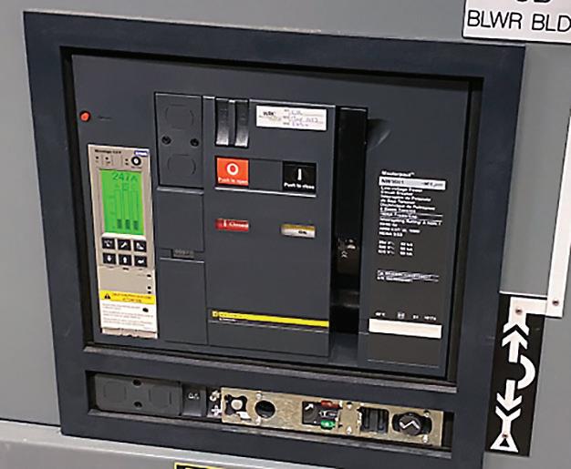
A lack of awareness and understanding of the technology features of new power circuit breakers and interlocks can lead to unsafe situations for maintenance personnel.
and specific Types) and for a high-voltage motor starter isolation a confusing mimic display on each motor starter where no formal training or procedure was in place.
Qualified persons (low-voltage and high-voltage qualified) were often not effectively trained concerning the isolation of new low- and high-voltage electrical power distribution equipment. Gaps in knowledge and a lack of competency on how to rack out or in a low-voltage power circuit breaker, how to complete a required “emergency extraction” racking out of a normally remotely racked high-voltage power circuit breaker when the onboard remote racking system fails, and isolation of a unique high-voltage motor starter were identified.
Is racking out or in a low- or high-voltage power circuit breaker simple? What about isolating a high-voltage motor starter? Are Kirk key interlocks involved? How many turns does it take to rack to “test,” and then how many additional turns to rack to “disconnected?” Are there special buttons the qualified person must push?
A critical component of risk related to the likelihood of occurrence related to energized electrical work tasks is ensuring the qualified person has the appropriate skills, knowledge, experience, and competency to perform the work. The employer must manage human performance and address the likelihood of human error. Racking out or in low- or high-voltage power circuit breakers and isolating unique high-voltage motor starters is not necessarily intuitive and simple. Qualified persons shall be suitably trained, follow a procedure, and have their competency validated before performing this type of work.
In the last decade, manufacturers have brought innovation to the industry with electrical equipment based on the concept of “safety by design/prevention through design (PtD)” related to the hierarchy of risk control methods to apply to an abnormal arcing fault and arc flash/electric shock. This has significantly benefitted the reduction of risk exposure to an abnormal arcing fault, arc flash, and electric shock. But has the qualified person received adequate training on this new electrical equipment? Do they make assumptions based on previous experience?
Depending on the manufacturer of low- or high-voltage power circuit breakers, this equipment may now have new unique interlocks. It may no longer be as simple as inserting the racking tool and racking the power circuit breaker out or in.
For high-voltage switchgear and power circuit breaker racking that has a provision for onboard racking only (with no through-door racking normally provided), what happens if this automated system fails? Has the qualified person been effectively trained to manually rack in and out the breaker? Is the manual “emergency extraction” racking simple? Is it the same as all the other power circuit breakers the qualified person has racked in or out in the past?
THE PROBLEM
The manufacturer’s instructions and labeling on high-voltage electrical equipment related to the isolation of a high-voltage motor starter with an integral disconnect switch may also not be intuitive concerning the operation of the disconnect switch and closing an included grounding switch. Is the manual easy to read? Does it include graphics, flow charts, and pictures to assist in understanding and application? Does the manufacturer have an approved video that could be used for training or referenced in a procedure?
The likelihood of human error increases when qualified persons do not have appropriate knowledge, skills, and experience. In this case, they may make assumptions based on previous knowledge/norms and have difficulty deciphering symbology that is not standardized in the industry.
Since their 2015 editions, NFPA 70E and CSA Z462 have included detailed requirements and supporting information related to risk assessment. Two parameters are evaluated: potential severity of injury or damage to health and likelihood of occurrence.
Concerning the likelihood of occurrence, NFPA 70E [Sec. 110.3(H) Risk Assessment Procedure and Sec. 110.3(H)(2) Human Error] and CSA Z462 [Clause 4.1.7.8 Risk Assessment Procedure and Clause 4.1.7.8.3 Human Error] place focus on ensuring the evaluation of human error is appropriately addressed and managed for the risk assessment procedure completed.
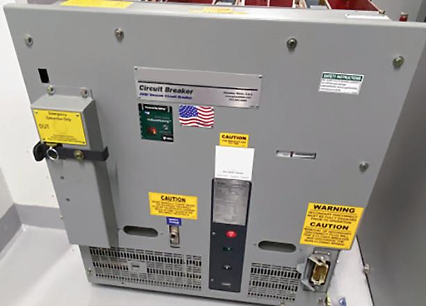
The emergency extraction of a breaker shall only be performed by a qualified person with proper training.
52 May 2024 • www.ecmweb.com
The risk assessment procedure shall address the potential for human error and its negative consequences on people, processes, the work environment, and equipment relative to the electrical hazards in the workplace. The potential for human error varies with factors such as the complexity of work tasks and the work environment. For more information regarding human error see, Annex Q and Annex U in the respective standards.
A risk management process flowchart can be found in NFPA 70E Annex F [Risk Assessment and Risk Control] and CSA Z462 Annex F [Risk Assessment and Risk Control]. See the Flow Chart on page 54. After the risk assessment procedure is completed, the employer and employee must confirm a field validation of expected risk control methods.
The likelihood of occurrence and the potential for human error in new electrical equipment designs needs to be evaluated and appropriate risk control methods applied, administrative controls, awareness, training, and procedures.
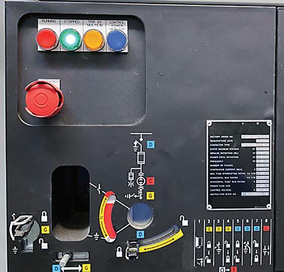
As outlined through the content of NFPA 70E Annex Q or CSA Z462 Annex U, Table Q.5 or Table U.1 Error Precursor Identification and Human Performance
Tool Selection, several error precursors can impact human error related to new electrical power distribution equipment designs with interlocks for racking in or out power circuit breakers, onboarding racking system automation, and the use of nomenclature for high-voltage motor isolations.
During three separate practical hands-on training sessions with experienced qualified persons, it was found that these individuals did not have appropriate knowledge and skills and were not competent concerning specific electrical equipment and manufacturer’s instructions for operating the electrical equipment for electrical equipment isolation. This is critically important to ensure the qualified person’s residual risk is managed and defendable when they are establishing electrically safe work conditions.
During the design basis memorandum (DBM) phase of a power system design, all available hierarchy or risk control methods shall be considered for electrical safety, and a cost-benefit analysis completed. What is lacking is ensuring that the capital project has funding available to provide technical skills training to qualified persons on the maintenance team on the new technology or updates to existing technology.
Arc-resistant electrical equipment designs have evolved and can also


supplies and more during the EASA 2024 Solutions Expo. ♦ Get in tune with expert-led training on topics ranging from technical skills to sales management and marketing. ♦ Solidify and develop relationships with electromechanical professionals from around the world!
www.ecmweb.com • May 2024 53
1331 Baur Blvd. St. Louis, MO 63132 USA +1 314 993 2220 easainfo@easa.com ♦ Build relationships with leading manufacturers and suppliers of electric motors, predictive and preventative maintenance equipment, bearings, pumps and pump
Caesars Forum & Harrah’s Las Vegas Register today at easa.com/convention! ATTEND THE HIGHLIGHT EVENT OF THE YEAR FOR ROTATING EQUIPMENT! Las Vegas CONVENTION ♦ JUNE 23-26 | SOLUTIONS EXPO ♦ JUNE 24-26 HAVE YOU JOINED EASA YET? EASA is the premier trade association servicing companies that repair, service and sell electric motors, pumps, drives and other electromechanical equipment. In-house facilities qualify, so join today and take advantage of all EASA offers, including live engineering support. Get started at easa.com/join. 2405ECM_EASA.indd 1 3/28/24 4:26 PM Close-up view of a high-voltage motor starter mimic display.
1 2 3 4 5 6
Employers and qualified employees must be familiar with this risk management process flow chart.
include the provision of remote power circuit breaker racking from an externally located panel. It is also important that the qualified person understand that the nameplate shall indicate the metal-clad switchgear is approved arc-resistant electrical equipment.
If automation of power circuit breaker racking is included, it can provide additional mechanical complexity and may be subject to failure. Manufacturers will include a provision for “emergency extraction of a power circuit breaker.” Is the qualified person appropriately trained and competent when the onboard automated racking system fails?
Training for a qualified person needs to include technical skills training related to any electrical equipment that will be worked on. If there are gaps in knowledge due to lack of this training, it can lead to uncertainty and increased likelihood of human error (see Table above).
HOW DO WE SOLVE THE PROBLEM?
Human error probability needs to be managed through the application of risk control methods.
Power circuit breaker racking (both low- and high-voltage) is not necessarily intuitive. New power circuit breakers may
Training Requirements
NFPA 70E [Sec. 110.4(A)(3)], Standard for Electrical Safety in the Workplace, and CSA Z462 [Clause 4.1.8.1.4 Retraining and Additional Training] outline prescriptive training requirements for a “qualified person” to receive periodic retraining in safety-related work practices and applicable changes to the standards at intervals not to exceed three years to maintain an appropriate level of awareness. Additional training shall be required if:
• Supervision or annual inspections indicate that the worker is not complying with safety-related work practices;
Human Error Precursor Identification Items
Interpretation
requirements
Confusing displays or controls
Obscure electrical supplies or configurations
Unfamiliar with or first time performing task
Lack of knowledge
New technique not used before Lack of proficiency or experience
Summary of human error precursor identification items.
include additional interlocks to be actuated to allow for insertion of the racking tool, racking the power circuit out or in, to the test position, and racking the circuit breaker out to the disconnected position. Symbology and nomenclature used may not be consistent with what the qualified person has been trained to understand.
Eliminating exposure by providing onboard motorized racking of high-voltage power circuit breakers eliminates exposure to arc flash, but what is required to “emergency extract” a power circuit breaker when the remote racking system fails? Knowledge, skills, experience, training, and the use of an “emergency extracting racking procedure” will drive the probability of human error down or eliminate it.
High-voltage motor starters and isolation may not be intuitive and will be confusing with the use of unfamiliar symbology and nomenclature. Specific manufacturer’s operating instructions require training, and the use of an electrical safe work procedure will ensure human error probability is managed. Knowledge retention and knowledge transfer are other positive outcomes of developing and using an electrically safe work procedure. The qualified person must be trained on, follow a procedure, and be competent for each manufacturer’s operating instructions with enhanced safety features. The bottom line is retraining or additional training may be required at regular intervals to maintain competency.
Terry Becker, P.Eng., CESCP, IEEE Senior Member is an electrical safety specialist and management consultant at TW Becker Electrical Safety Consulting, Inc. (www.twbesc.ca) and can be reached at 1-587-433-3777 or at terry.becker@twbesc.ca.
• New technology, new types of equipment, or changes in procedures necessitate the use of safety-related work practices that are different from those that the worker would normally use;
• The worker needs to employ tasks that are performed less often than once per year;
• The worker needs to employ safety-related work practices that are not normally used during the worker’s regular duties; or
• The worker’s job duties change.
54 May 2024 • www.ecmweb.com
RISK ASSESSMENT Establishing the Context Risk Control Methods Identified to Be Applied in the Field Hazard Identification Risk Analysis Risk Evaluation
Monitor and Review
NEW PRODUCT SHOWCASE
Focus on Safety Equipment, Workwear, and PPE
Eye Protection
The Vader goggle is equipped with a BK-Anti-FOG coating and a durable antiscratch treatment. It is D3 rated for droplet and splash protection. Vader’s built-in venting system helps reduce the potential for moisture buildup, helping to maintain clear vision. According to the company, the only material that touches the user’s face is an ultra-soft conditioned rubber that forms the splash shield. The product provides 99.9% UV protection and fits over most prescription eyeglasses. Additionally, it meets industry test requirements (ANSI Z87.1+, EN166K, EN166N, EN166UV) and meets or exceeds AS/NZS 1337.1:2010 for eye and face protection. Brass Knuckle

Head Protection
Fall Protection

The B7-Comfort Tower climbing harness has an integrated hip O-ring design, a 3-in. sub-pelvic strap, and a replaceable aluminum-based adjustable seat sling. According to the company, the B7-Comfort Tower was designed for superior mobility, climbability, and comfort when climbing/positioning at height all day. The harness also incorporates features such as DiaLock torso adjusters, adjustable shoulder and waist pads, integrated trauma strap leg pads, all-aluminum hardware, and premium comfort materials. Guardian
BOLT safety helmets with an IMPACT ARMOR liner allow users to deploy multiple accessories at once and include a BOLT headlamp mount that works with most headlamps for easy, secure attachment. The BOLT marker clip allows for easy access to pens and markers. The helmets have a comfortable padded suspension that includes an adjustable swinging ratchet and an adjustable chin strap for better security. According to the company, these safety helmets are American National Standards Institute (ANSI) Type 2 rated and are customizable with the ability to add a company logo in up to four locations on the helmet. Milwaukee Tool
Sun and Heat Protection
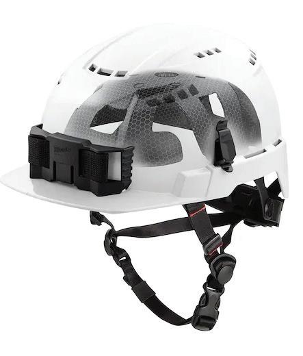
The cooling helmet liner with nape offers strong sun and heat protection. The accessory features longlasting cooling technology, UPF 50 sun protection, and chemical-free cooling. According to the company, the product is designed to keep workers cool, comfortable, and protected on the job. The liner stays cool for up to 2 hr, is machine-wash friendly, and has a fabric content of 92% polyester and 8% spandex.
STUDSON
www.ecmweb.com • May 2024 55
PRODUCT NEWS
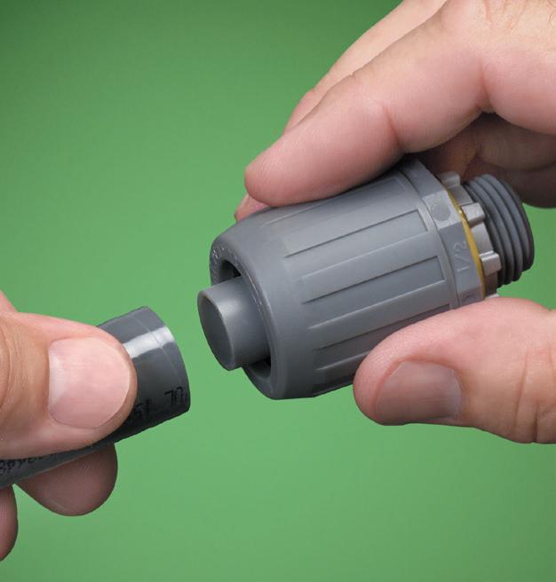
Push-On Connectors
The larger, non-metallic push-on connectors are now available in 1.25-in., 1.5-in. and 2-in. sizes. According to the company, its push-on connectors offer the fastest, easiest way to install non-metallic liquid-tight conduit, type B. These listed one-piece connectors reduce labor steps and eliminate lost pieces. The product ships fully assembled; no disassembly needed. In addition, the connectors are removable and reusable.
Arlington Industries
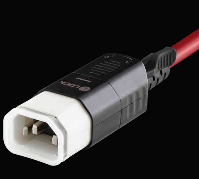
Dual-Locking Power Cable Series
The L-LOCK universal dual-locking power cable series eliminates accidental disconnects by securely locking both cable ends to electronics and power equipment regardless of make and manufacturer. The L-LOCK latch system locks and unlocks with a finger press. The product is available in multiple connector configurations, colors, and lengths, ensuring equipment uptime by securely locking into equipment ports. It is also universally compatible with electronics and power equipment.
NSI Industries

Work Boot
The Marin 6-in. soft toe boot is built for workers across a variety of trades. The product features a barnyard-resistant leather sourced from Texas steer and a fully waterproof build that’s loaded with hardwearing durability. The Marin comes fully equipped with an innovative slip-, oil-, and heat-resistant rubber outsole. The product is electrical hazard rated, has a heat-resistant sole of up to 572°F, and meets ASTM F2892-18 standards.
BRUNT Workwear
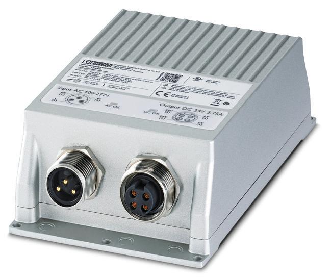
Power Supplies
The IP 67-rated TRIO power supplies can be mounted directly on machines or in the field, providing stable power to localized control systems at the edge of an application. The devices have UL 1310 certification and can create energy-limited NEC Class 2 circuits. Direct installation puts the power where it’s needed and reduces cable lengths. The devices are designed for smaller or more sensitive loads and are available in four connection styles for mounting flexibility. Finally, the robust die-cast aluminum housing resists extreme environmental conditions such as temperature, dust, and water.
Phoenix Contact

Digital Multimeter

The 600V automatic intelligent digital multimeter is an auto-function volt meter capable of gauging both the required range and the required function based on the test lead input, providing accurate results. Simply plug in the leads and connect to the test subject. It tests AC and DC voltage, resistance, capacitance, frequency, diode, duty cycle, continuity, automatic current input detection, and live testing, non-contact voltage detection (NCV). The product has a backlit display for low-light and high-light environments and includes a hard carrying case.
Jonard Tools
Outdoor Luminaires
Lupa luminaire offers modern, minimalist styling with optics that create an inviting, glare-free experience. Lupa features a disk shape, no visible hardware, and a seamlessly integrated arm to bring a contemporary feel and refined look to public spaces. According to the company, Lupa’s light engine features the latest ink technology in its diffuser to deliver broader, more even light distribution. The product has a cast aluminum housing. It is available in performance packages from P10 (3,260 delivered lm) to P50 (15,880 delivered lm).
Cyclone Lighting
56 May 2024 • www.ecmweb.com
CODE BASICS
NEC Requirements for Services — Part 2
Do you know the rules for service-entrance conductors and service disconnects?
By Mike Holt, NEC ConsultantService-entrance conductors differ from service conductors. They are the conductors between the terminals of the service equipment and the service drop, overhead service conductors, service lateral, or underground service conductors [Art. 100]. By contrast, service conductors run from the service point to the service disconnect [Art. 100].
Each service drop, service lateral, or set of underground or overhead service conductors can supply only one set of service-entrance conductors [Sec. 230.40]. There are five exceptions. For example, Exception No. 2: Serviceentrance conductors can supply two to six service disconnects per Sec. 230.71(B).
Service conductors must have an ampacity of at least the largest of the calculations in Sec. 230.42(A)(1) or (2) [Sec. 230.42]. For example, service conductors must have an ampacity of at least 125% of the continuous loads, plus 100% of the noncontinuous loads, based on the temperature rating of equipment per Sec. 110.14(C)(1) and Table 310.16, before conductor ampacity correction and/or adjustment [Sec. 230.42(A)(1)].
The service neutral conductor must have an ampacity to carry the maximum unbalanced load per Sec. 220.61 and not be smaller than required by Sec. 250.24(D) [Sec. 230.42(C)].
Service-entrance conductors can be installed with any of the 21 wiring methods listed in Sec. 230.43 —for example, wireways, EMT, and MC cable.
Pressure connectors, devices for splices and tap connections, and power distribution blocks installed on service conductors must be listed and marked

1. Section 230.46 requires pressure connectors, devices for splices and tap connections, and power distribution blocks installed on service conductors to be listed and marked “suitable for use on the line side of the service equipment” or equivalent.
“suitable for use on the line side of the service equipment” or equivalent [Sec. 230.46], as shown in Fig. 1.
You must protect service-entrance cables subject to physical damage using one of the six methods listed in Sec. 230.50(B)(1) through (6). For example, use EMT.
Service-entrance cable must be supported within 1 ft of the weatherhead, gooseneck, raceway connections, or enclosure. Supports must be at intervals not exceeding 30 in. [Sec. 230.51(A)].
Service weatherheads on raceways or service-entrance cables must be above the point of attachment [Sec. 230.26]
for service-drop or overhead service conductors [Sec. 230.51(C)].
Exception: If it is impractical to locate the service head above the point of attachment, it must be within 2 ft of the point of attachment.
Drip loop conductors must be connected to the service-drop or overhead service conductors below the service head or termination of the serviceentrance cable sheath [Sec. 230.51(F)].
On a 4-wire, delta-connected, 3-phase high-leg system, the conductor with the higher phase voltage-to-ground (208V high-leg) must be durably and permanently marked by an orange outer finish
www.ecmweb.com • May 2024 57
Fig.
CODE BASICS


CodeWatch
This e-newsletter, published four times per month, is dedicated to coverage of the National Electrical Code. The content items are developed by well-known Code experts.
CodeWatch promises to:
• Explain how to properly apply the Code
• Test your knowledge of the Code
• Provide information on upcoming Code-related seminars and shows
• Offer Code quizzes and real-world Code violations
Subscribe Today
See all of our EC&M e-newsletters at www.ecmweb.com
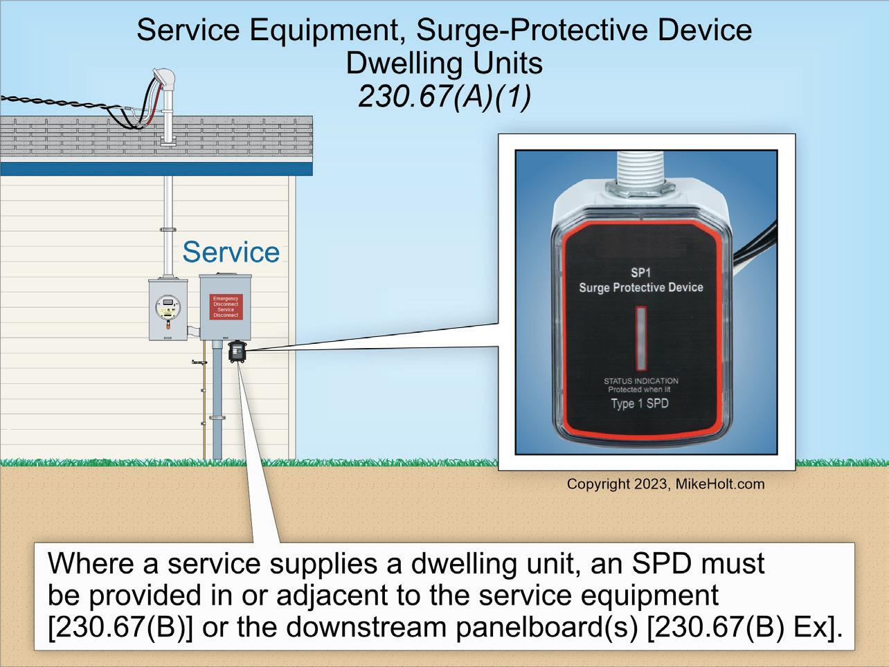
Fig. 2. Per Sec. 230.67(A)(1), where a service supplies a dwelling unit, you must provide a surge-protective device.
or other effective means [Sec. 230.56]. Such identification must be placed at each point on the system where both a connection is made and the neutral conductor is present [Sec. 110.15].
SURGE PROTECTION
Where a service supplies any of the following occupancies, you must provide a surge-protective device [Sec. 230.67(A)]:
(1) Dwelling units (Fig. 2).
(2) Dormitory units.
(3) Guest rooms and guest suites of hotels and motels.
(4) Areas of nursing homes and limited care facilities used exclusively as patient sleeping rooms.
The surge-protective device must be a Type 1 or Type 2 SPD [Sec. 230.67(C)] and must be an integral part of the service disconnect or be immediately adjacent to the service disconnect [Sec. 230.67(B)]. Exception: The surge-protective device is permitted to be at the downstream panelboard.
SERVICE DISCONNECT
The service disconnect must be marked to identify it as suitable for use as service equipment and must be permanently marked to identify it as a service disconnect [Sec. 230.66(A)].
The service disconnect must open all phase conductors [Sec. 230.70]. It must be placed at a readily accessible location either outside the building or inside nearest the point of service conductor entry [Sec. 230.70(A)(1)].
Each service must have only one service disconnect except as permitted in Sec. 230.71(B). Each service can have up to six service disconnects per Sec. 230.71(B)(1) through (5) — for example, panelboards with a service disconnect in each panelboard.
The service disconnects for each service must be grouped and marked to indicate the load served [Sec. 230.72(A)].
To minimize the possibility of simultaneous interruption of power, the disconnect for fire pumps [Art. 695], emergency systems [Art. 700], legally required standby systems [Art. 701], or optional standby systems [Art. 702] must be remote from the service disconnect(s) for normal service [Sec. 230.72(B)].
The service disconnect for a building must have an ampere rating of at least the calculated load per Art. 220, and in no case can it be less than the values listed in Sec. 230.79(A) through (D). For example, for installations consisting of two 2-wire branch circuits, the disconnect must have an ampere rating of at least 30A.
58 May 2024 • www.ecmweb.com
Only 11 types of electrical equipment can be connected to the supply side of the service disconnect [Sec. 230.82]. For example:
• Cable limiters.
• Meters and meter sockets rated at least 1,000V.
• Type 1 SPDs.
• Emergency disconnects for oneand two-family dwelling units.
EMERGENCY DISCONNECT
For one- and two-family dwelling units, an emergency disconnect must be installed per Sec. 230.85(A) through (E).
(A) General. The requirements are about what you’d expect: readily accessible, within sight from the dwelling unit, has a short-circuit rating of at least that of the available fault current, and grouped if more than one disconnect (Fig. 3).
(B) Type. It has to be a service disconnect, integrated meter disconnect, or other listed switch or circuit breaker suitable for service equipment.
(C) Replacement. Where a service disconnect is replaced, all the requirements of this section apply.
(D) Identification. Where disconnects for other energy source systems are not adjacent to the emergency disconnect, a plaque or directory identifying the location of all other energy source disconnects must be adjacent to the emergency disconnect.
(E) Marking. There are five marking requirements. For example, the markings or labels must be on the outside front of the disconnect with a red background and white text.
SERVICE CONDUCTOR OVERCURRENT PROTECTION
Each service phase conductor must have overload protection [Sec. 230.90].
The service overcurrent protective device provides overload protection for the line side of service conductors, but not short-circuit and ground-fault protection because that protection can be provided only at the supply end of a circuit.
The rating of the overcurrent protective device must not be greater than the ampacity of the service phase conductors [Sec. 230.90(A)].
Exception No. 2: If the ampacity of the phase conductors does not correspond

Fig. 3. Section 230.85(A) requires the emergency disconnect to be readily accessible, within sight from the dwelling unit, and have a short-circuit rating at least that of the available fault current.
with the standard rating of overcurrent protective devices as listed in Sec. 240.6(A), the next higher overcurrent protective device can be used if it does not exceed 800A [Sec. 240.4(B)].
Exception No. 3: The combined ratings of two to six service disconnects can exceed the ampacity of the service conductors only if the calculated load does not exceed the ampacity of the service conductors per Art. 220.
Exception No. 5: Overload protection for dwelling unit services is permitted per the requirements of Sec. 310.12.
The service disconnect fuse or circuit breaker supplies overload protection — but not short-circuit and ground-fault protection — for the line-side service conductors.
The service grounded conductor can terminate on a circuit breaker that simultaneously opens all conductors of the circuit [Sec. 230.90(B)]. A breaker so configured is the only overcurrent device that can be inserted into a grounded service conductor.
The service overcurrent protective device must be an integral part of the service disconnect or be immediately adjacent to the service disconnect [Sec. 230.91]. Where fuses are used as the service overcurrent protective device, the disconnect must be ahead of the supply side of the fuses.
Each service disconnect rated 1,000A or more supplied by a 4-wire, 3-phase, 277V/480V wye-connected system must be provided with groundfault protection of equipment [Sec. 230.95]. The rating of the service disconnect is based on the rating of the largest fuse that can be installed or the circuit breaker’s highest continuous current trip setting.
CODE-COMPLIANT SERVICES
Article 230 is one of the larger Articles in the Code. It’s also complex, with many rules that can be hard to check at the drawing desk or in the field. This fact has not gone unnoticed by CodeMaking Panel Number 10 (the CMP responsible for Art. 230). For many Code cycles now, Figure 230.1 has provided both a list and a graphic that show you how Art. 230 is laid out.
You can see at a glance that if you’re working with overhead conductors, you need to refer to Part II. However, if those conductors are underground you need to refer to Part III. So look at this table to identify which Part of Art. 230 matches where you are in your design workflow or installation process.
Don’t confuse service conductors (Parts II and III) with service-entrance conductors, either.
www.ecmweb.com • May 2024 59
Test Your Code IQ
How much do you know about the National Electrical Code?
By Mike Holt, NEC ConsultantAll questions and answers are based on the 2023 NEC.

Q1: Equipotential planes shall be installed adjacent to all outdoor service equipment or disconnecting means that control equipment in or on water in marinas and docking facilities where the system voltage exceeds _____ to ground.
a) 120V c) 220V
b) 125V d) 250V
Q2: Areas designated as hazardous (classified) locations or determined to be unclassified shall be _____ and shall be available to the authority having jurisdiction and those authorized to design, install, inspect, maintain, or operate electrical equipment at these locations.
a) cleaned
b) documented
c) maintained
d) all of these
Q3: The _____ and other characteristics of the circuit to be protected shall be
selected and coordinated to permit the circuit protective devices used to clear a fault to do so without extensive damage to the electrical equipment of the circuit.
a) overcurrent protective devices
b) total impedance
c) equipment short-circuit current ratings
d) all of these
Q4: Where a mast is used for overhead branch-circuit or feeder conductor support, it shall have adequate _____ or be supported by braces or guy wires to safely withstand the strain imposed by the conductors.
a) strength
b) mobility
c) length
d) size
Q5: An equipment bonding jumper can be installed on the outside of a raceway,
provided the length of the equipment bonding jumper is not more than _____ long and the equipment bonding jumper is routed with the raceway.
a) 3 ft c) 5 ft
b) 4 ft d) 6 ft
Q6: If a/an _____ or less overcurrent protective device is an adjustable trip device installed in accordance with Sec. 240.4(B)(1), (B)(2), and (B)(3), it shall be permitted to be set to a value that does not exceed the next higher standard value above the ampacity of the conductors being protected as shown in Table 240.6(A) where restricted access in accordance with Sec. 240.6(C) is provided.
a) 600A c) 1,000A
b) 800A d) 1,200A
See the answers to these Code questions online at ecmweb.com/55021907.


CODE QUIZ OF THE MONTH 60 May 2024 • www.ecmweb.com
19430173 © Franku Dreamstime.com
Photo
WHERE FACILITY CHALLENGES FIND SOLUTIONS
NORTHERNCALIFORNIA
August 21-22, 2024
Reno, NV NORTH TEXAS
October 29-30, 2024
Irving, TX
October 9-10, 2024
Santa Clara, CA


O W N E D & P R O D U C E D BY: facilitiesexpo.com
RENO
CODE VIOLATIONS
Illustrated Catastrophes
By Russ LeBlanc, NEC ConsultantAll references are based on the 2023 edition of the NEC.
WHERE’S THE BOX?
Some of our readers may be old enough to remember the catchphrase “Where’s the beef?” that became famous in 1984 as a slogan for the fast-food restaurant Wendy’s. This installation reminds me of that TV commercial and has me asking: “Where’s the box?”
It sure looks as though there was never a box installed here. The fixture bar and the white outline on the bricks are clues that there was probably a luminaire installed here at some point. While I have seen many luminaires installed on fixture bars secured directly to the building without using a box — as was done here — it was most likely a Code violation when it was originally installed. It would certainly be a violation to use this method today.
Section 300.15 requires boxes to be installed at outlet points, such as luminaires. Another problem is
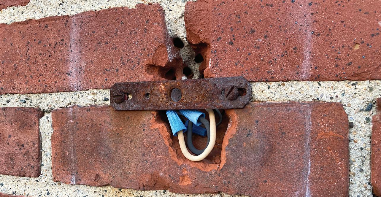
the lack of sunlight resistance for the wire connectors and conductors. Close inspection revealed signs of brittleness and damage. Section 310.10(D) requires insulated conductors used where exposed to direct sun to be listed as sunlight resistant or
DISASTROUS DOCK WIRING
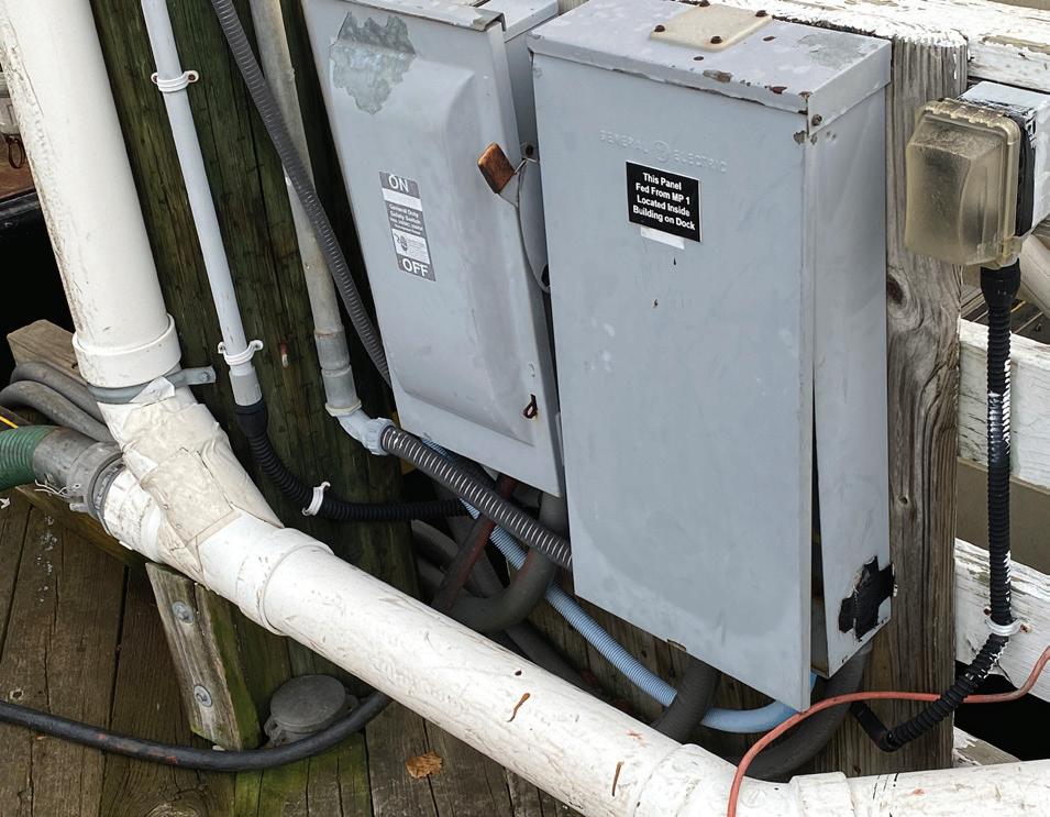
There are many violations to point out here. The blue electrical nonmetallic tubing (ENT) installed beneath the panelboard enclosure and the disconnect enclosure is a violation
covered with an insulating sleeve or tape listed as being sunlight resistant. Unless identified for the environment, no conductors or equipment should be used where the operating environment will cause deterioration as specified in Sec. 110.11.
of Sec. 362.12(7) because it’s not identified as being sunlight resistant. The gray liquidtight flexible nonmetallic conduit (LFNC) beneath the disconnect is also faded and showing signs of sunlight damage. There are no requirements in Sec. 356.10 specifically permitting LFNC to be installed in the direct sunlight. Section 356.10(3) does permit LFNC outdoors where listed and marked for this purpose but does not mention installations in direct sun. Simultaneously, nothing in Sec. 356.12 specifically prohibits LFNC from being installed in direct sun. LFNC installed in direct sunlight must be listed or identified for this purpose as specified in Sec. 300.6(C)(1).
The white PVC drain line installed in front of the panelboard and disconnecting means is a violation of the working space requirements specified in Sec. 110.26(A). The black LFNC connected to the receptacle box on the right side is snapped and broken apart near the bottom right corner of the panelboard enclosure. This broken raceway is a violation of Sec. 110.12(B). Lastly, the black duct tape used to cover the missing knockout for the panelboard enclosure does not comply with Sec. 110.12(A).
62 May 2024 • www.ecmweb.com
ADVERTISER INDEX
(Every effort is made to ensure the accuracy of this index. However, the
To place a display ad (1/6 page or larger), call the Advertising Sales Representative for your area.
Vice President
Mike Hellmann
Andover, MA • Phone: (978) 289-0098
E-mail: mhellmann@endeavorb2b.com
Western U.S. & Western Canada
Ellyn Fishman, Key Account Manager (949) 239-6030
Email: efishman@endeavorb2b.com
Northeast U.S. & Eastern Canada
David Sevin, Account Manager 24 Houghton Street • Barrington, RI 02806 Phone: (401) 246-1903
E-mail: dsevin@endeavorb2b.com
Midwest, Southeast,and Southwest
Jay Thompson, Account Manager
7450 W. 130th Street, Suite #210
Overland Park, KS 66213 • Phone: (913) 967-7543
E-mail: jthompson@endeavorb2b.com
Marketplace/Inside Sales
Steve Suarez, Media Account Exec
7450 W. 130th Street, Suite #210
Overland Park, KS 66213 • Phone: (816) 588-7372
E-mail: ssuarez@endeavorb2b.com


www.ecmweb.com • May 2024 63
Advertiser Page # Phone # Web Address Arlington Industries, Inc. 15 800-233-4717 www.aifittings.com Arlington Industries, Inc. 17 800-233-4717 www.aifittings.com Arlington Industries, Inc. 19 800-233-4717 www.aifittings.com Arlington Industries, Inc. 21 800-233-4717 www.aifittings.com Arlington Industries, Inc. 23 800-233-4717 www.aifittings.com Arlington Industries, Inc. 25 800-233-4717 www.aifittings.com Arlington Industries, Inc. 27 800-233-4717 www.aifittings.com Arlington Industries, Inc. 29 800-233-4717 www.aifittings.com Arlington Industries, Inc. 31 800-233-4717 www.aifittings.com Arlington Industries, Inc. 33 800-233-4717 www.aifittings.com Arlington Industries, Inc. 35 800-233-4717 www.aifittings.com Arlington Industries, Inc. 39 800-233-4717 www.aifittings.com Arlington Industries, Inc. 41 800-233-4717 www.aifittings.com Arlington Industries, Inc. 43 800-233-4717 www.aifittings.com Arlington Industries, Inc. 45 800-233-4717 www.aifittings.com Arlington Industries, Inc. 47 800-233-4717 www.aifittings.com Arlington Industries, Inc. 49 800-233-4717 www.aifittings.com Arlington Industries, Inc. 51 800-233-4717 www.aifittings.com Arlington Industries, Inc. 64 800-233-4717 www.aifittings.com Atkore IFC www.atkore.com Champion Fiberglass, Inc. 13, BC www.championfiberglass.com EASA - Electrical Apparatus Service Association 53 314-993-2220 www.easa.com/convention FacilitiesExpo 2024 61 www.facilitiesexpo.com Glen Raven Technical Fabrics 11
Hubbell Wiring Devices 9, 28
Mike Holt Enterprises IBC 888-632-2633 www.mikeholt.com Penn Aluminum Conduit & EMT 1 www.pennconduit.com Progressive Insurance 7
S-P Products, Inc. 5 800-233-8595 www.SPProducts.com Underground Devices, Inc. 3 847-205-9000 www.udevices.com
www.glenguard.com
www.hubbell.com
www.ProgressiveCommercial.com
publisher cannot be held responsible for errors or omissions.)
DOWNLOAD GUIDE ADVANCE RENEWABLES PROJECTS WITH PREMIUM CONDUIT Low coefficient of friction allows for smooth pulls No burn-through eliminates elbow repairs Fault resistance
cables easy Mechanical strength protects cables 2404ECM_ChampionFiberglass_MKPL.indd 1 3/28/24 4:56 PM
makes repairing
CODE VIOLATIONS
By Russ LeBlanc, NEC ConsultantHow well do you know the Code? Think you can spot violations the original installer either ignored or couldn’t identify? Here’s your chance to moonlight as an electrical inspector and secondguess someone else’s work from the safety of your living room or office. Can you identify the specific Code violation(s) in this photo?
Note: Submitted comments must include specific references from the 2023 NEC.
Hint: Wrong receptacle layout
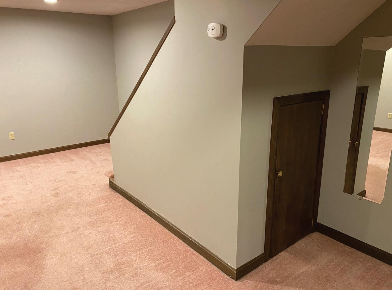
‘TELL THEM WHAT THEY’VE WON...’
Using the 2023 NEC, correctly identify the Code violation(s) in this month’s photo — in 200 words or less — and you could win an Arlington Industries 18-in. Slider Bar and plastic box for mounting between studs with non-standard spacing. E-mail your response, including your name and mailing address, to russ@russleblanc.net, and Russ will select three winners (excluding manufacturers and prior winners) at random from the correct submissions. Note that submissions without an address will not be eligible to win.
MARCH WINNERS
Our winners this month were Gabe Kaprelian, an electrical contractor from Valley Glen, Calif.; Richard B. Everett, an EC&M reader from Hamilton, N.J.; and Juan C. Hernandez, a contest participant from Germantown, Md. They were able to correctly cite Code violations in this photo.
Section 760.121(B)(5) permits the fire alarm branch-circuit disconnecting means to be secured in the “on” position; however, Sec. 240.24(A) requires circuit breakers to be readily
accessible, and “circuit breaker locks” that require the use of a screwdriver to remove do not provide for a circuit breaker that will meet the Art. 100


definition of “readily accessible.” The red paint used to mark the fire alarm circuit breakers creates a violation of Sec. 240.83(A) because the ampere rating of the circuit breakers is completely obscured by the paint. Section 760.121(B)(4) requires the branch circuits for fire alarm equipment to have red identification; however, that red identification must not obscure any manufacturer’s markings. The red paint used on those three circuit breakers is not Code-compliant.

64 May 2024 • www.ecmweb.com
B I ENTER to WIN... SL1B18 SINGLE GANG KIT SLIDER BAR™ mounts plastic (or metal) boxes between studs with non-standard spacing 2106ECM_Arlington_StripAd.indd 1 6/9/21 9:41 AM


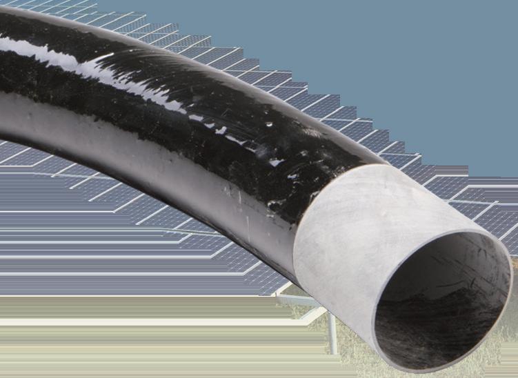

ADVANCE RENEWABLES PROJECTS WITH
PREMIUM CONDUIT
Low coefficient of friction allows for smooth pulls
No burn-through eliminates elbow repairs

DOWNLOAD FIBERGLASS VS GRC COMPARISON
Fault resistance makes repairing cables easy
Mechanical strength protects cables
©2016 Champion Fiberglass, Inc. BIM/REVIT
Champion Fiberglass® Elbows