HEALTH & SAFETY ENGINEERING Designation
Dynamic Penetration Rating
P1
≤1 m (3.3 ft)
P2
1.01 to 7 m (3.31 to 23.0 ft)
P3
7.01 to 30 m (23.1 to 98.4 ft)
P4
30 m (98 ft) or greater
V/7500(N2)/80/90:0/1.2 V
7500
(N2)
80
90
0
1.2
Vehicle
Test Weight of Vehicle (shown in Kg)
Vehicle Class
Speed of Vehicle (shown in KPH)
Angle (angle at which the vehicle hit the barrier)
Penetration of Vehicle (shown in metres)
Dispersion (debris dispersion shown in metres)
Table 1: Classification of penetration ratings
Table 2: Interpreting the PAS 68 Classification Code
Test standards Several codes and guidelines have been developed to assist in the testing and certification of crash barriers. ASTM F2656-07 ‘Standard Test Method for Vehicle Crash Testing of Perimeter Barriers’ is an accredited test method which provides a structured procedure to establish a penetration rating for vehicle perimeter barriers subjected to vehicle impacts. The test standard designates six types of vehicles and four different test speeds as the impact conditions, and assigns corresponding penetration distances as classification ratings for the tested VSBs. The classification of penetration ratings are presented in Table 1.These ratings are based on the measurements of the extent to which the test vehicle penetrates or vaults over the reference point of the barrier. British Standards Institute (BSI) also published PAS 68 which has become the UK’s standard and specifications for vehicle security barriers tests. The test standard and classification code rates the crash barrier, based on information such as vehicle mass, test speed, impact angle, penetration and dispersion of major debris. . Table 2 depicts an example of interpreting the classification code.
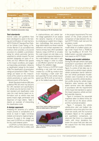
in crashworthiness and vehicle barrier design applications. It can analyse the dynamic response of structures by employing an explicit time integration methodology that accounts for large deformations, non-linear material behaviour and contact separation behaviour, among many other specialised features. Using LS-DYNA to simulate the crash impact not only helps us to understand the response behaviour of the crash bollards, it also aids in optimising the design, in order to create a cost-effective specimen for physical testing in the validation stage. Figure 4 shows a LS-DYNA model simulating a real crash test scenario created by a 6,708 kg medium-duty truck impacting a triple crash bollard assembly. The test vehicle impact speed was 48.76 km/h at normal angle to the bollard assembly, as stated
A design approach Analysing the dynamics of a vehicle impact process is complicated, as it tends to result in highly non-linear, inelastic and dynamic engineering behaviours. To assist in the design, we have used LS-DYNA as a design tool for the crash bollards system. LS-DYNA is a finite element analysis (FEA) software that is widely used
Figure 4:Truck vehicle (6,708 kg) impacting the centre of a bollard system at 48.76 km/h
Figure 5:Tow tug (70,000 kg) impacting a bollard system at 30 km/h
in the project requirements. The next section of this article presents the comparison of data between the actual ASTM F2656 crash test and the simulation model. Figure 5 shows another LS-DYNA model detail, of a bollard system design under impact from a 70,000 kg tow tug travelling at 30 km/h. The bollard system was later subjected to tests based on ASTM F2656. Testing and model validation During the full-scale vehicle crash tests, conducted in accordance with ASTM F2656-07, on the vehicle modelled in Figure 4, a series of test data was recorded, such as vehicle impact velocity, vehicle acceleration, barrier deformation and vehicle penetration. Accelerometers were mounted on the test vehicle, to record the vehicle deceleration profile during the vehicle impact. Real-time video cameras and highspeed cameras were also deployed, in accordance with the requirements of the impact test standard, to capture the impact sequence, vehicle and bollard assembly response. Figure 6 compares the sequential snapshots taken at distinct times, for the crash test on the above vehicle and the numerical simulation. Figure 7 compares the vehicle velocity-time plot and bollard displacement versus time plot, from the crash test results, with the numerical simulation. Based on the qualitative and quantitative comparisons, we observed that there is a reasonable match, with minor deviations, between the actual field test data and the outputs from the finite element vehicle model.
December 2016 THE SINGAPORE ENGINEER
31