BUILDING STUDYREPORT
BLOCK 6 CHANDIGARH UNIVERSITY (SOUTH CAMPUS)
BACHELOR OFARCHITECTURE
PRACTICAL TRAINING PROGRAMME 2022
SUBMITTED BY: DEEPANSHU
1916430
7TH SEMESTER
I.K. GUJRAL P.T.U. MOHALI CAMPUS II, MOHALI KHARAR- BANUR HIGHWAY, KHUNNIMAJRA, SECTOR 115, MOHALI
CONSTITUENT CAMPUS OF
I.K. GUJRAL PUNJAB TECHNICAL UNIVERSITY, JALANDHAR
KAPURTHALA-JALANDHAR HIGHWAY, KAPURTHALA

ACKNOWLEDGEMENT
I would like to express my deep gratitude to Ar.Aman Aggarwal, Principal architect, Charged Voids for his inspiration, support and guidance.
I would like to thank Ar. Rahul Vig, Ar. Javed Akhtar Siddiqui and Ar. SwatiAggarwal for their insightful critiques that have helped me for better understanding.
Ahuge shout out to my super - cool “seniors/mentors” – Ar. ShubhamThakral, Ar. Tanvir Singh Narang, Ar Sukhmani Kaur, Ar. Malvika Dhiman, Ar. Shivam Dhawan for consistently giving me their inputs at various stages of the training journey. Your refreshing points of view have always been helpful in understanding many things –about buildings and people inside them.
I would like to extend my gratitude to Yukta Garg, Sanya Jain and Japesh Gupta for their help and support being there with me.
For all my colleagues who helped me and supported me during the time I need, you have my heartfelt thanks.
Deepanshu Manarya
ABOUT CHARGED VOIDS
Charged voids is a Chandigarh-based architectural firm that explores the possibilities of a transcendent and spiritual character in architecture. Their work is underpinned by a purposeful dialogue between western modernism and elements of Indian architecture. They create spaces that best contribute to the human experience. The inquiry-based design approach is original, challenging and reimagining established benchmarks for how we live, work. play, and perceive space.
Context and climate-responsive design serve as a cornerstone for the practice, combining simplicity with functional efficiency. Making economical use of resources, employing a thoughtful material palette that bolsters building performance and leaves minimal environmental footprints, as well as a timeless, enduring imprint on the people it serves. They believe that all of architecture is driven by two sets of elemental considerations: the Constants and the Variables.
The variables that today’s design technology utilizes to optimize building designs. These determinants are the focus of our education system and the industry at large. The constants, however, transcend the tangible. Factoring in these universals, namely gravity, light, elements of nature, and human perception.

CANDIDATE’S DECLARATION
I Deepanshu, the author of the training report from 25th of July to 3rd of December hereby declare that this is an independent work of mine, carried out towards the partial fulfillment of the requirements for the award of the bachelor’s degree in architecture at the I.K.G. PTU CAMPUS, MOHALI-II, SECTOR-115.
The work has not been submitted to any other organization/ Institution for the award of any Degree/ Diploma.
DEEPANSHU
ROLL NO. 1916430
B.ARCH 7TH SEMESTER (2019 – 2024)
I.K.G P.T.U CAMPUS MOHALI-II
Date: Place: Signature
ABSTRACT
Architecture, unlike other fields of engineering is truly a practical field where learning is process. The results here are directly relative to the need and demand of humans. Form and Function are two vital parts of architecture.
Internship is a practical section of a course of study. As specified in theArchitecture curriculum of I.K.G. P.T.U. Mohali, Campus II, students qualify to gain the practical knowledge by working as a trainee Architect in an architectural firm registered and run by professionals. Internship in Architecture is vital session. Students not only get a semester long theoretical break but also an opportunity to Imagine the Architectural field beyond their drafting table and presentation board. It is a supervised practical application of previously studied theory.
During the internship period, students gain immense insight regarding the real facts of architecture. This course helps to train students in various fields such as in technical, economical, practical and drawings, estimation and costing. In dealing with different professional’s engineers, clients. It basically prepares students and makes them laminar with the office environment and trends. During my internship, I pined CHARGED VOIDS, as a trainee architect for over 19 weeks. This report reflects my experience as trainee architect on various projects aiming to develop practical knowledge on the architectural fields.
ACKNOWLEDGEMENT ABOUT CHARGED VOIDS
CANDIDATE’S DECLARATION ABSTRACT
TABLE OF CONTENTS
AIM, OBJECTIVE & SCOPE OF STUDY
CHAPTER 1 : ABOUT THE PROJECT
1.1 PROJECT PROFILE
1.1.1 INTRODUCTION
1.2 SITE PROFILE
1.2.1 SITE ANALYSIS
1.2.2 SITE AND CONTEXT IMAGES
1.2.3 CLIMATOLOGY AND TOPOGRAPHY
1.2.4 SOCIAL, ECONOMIC AND HERITAGE CHARACTER
CHAPTER 2 : DESIGN AND PLANNING
2.1 ARCHITECT’S CONCEPT
2.2 BUILT FORM VISION
2.3 SPATIAL ZONING
2.4 MOVEMENT AND CIRCULATION
2.5 SUN PATH AND NATURAL VENTILATION
2.6 BUILDING BYE- LAWS
2.7 AREA PROGRAM SUMMARY
S.W.O.T ANALYSIS OF SITE
CHAPTER 3 : ARCHITECTURAL DRAWINGS
3.1 FLOOR PLANS
3.2 ELEVATIONS
3.3 SECTIONS
3.4 RENDERS VS SITE
3.5 ARCHITECTURAL ELEMENTS
CHAPTER 4 : CONSTRUCTION/ STRUCTURE
4.1 COLUMN GRID PLAN
4.2 PLINTH BEAM DRAWINGS & DETAILS
4.3 GROUND FLOOR SHUTTERING & DETAILS
4.4 MATERIAL PALETTE INTERIOR & EXTERIOR
4.5 ENTRANCE RAMP DRAWINGS
CHAPTER 5 : BUILDING SERVICES
5.1 ELECTRICAL LAYOUT DRAWINGS
5.2 PLUMBING & FIRE FIGHTING LAYOUT DRAWINGS
CHAPTER 6 : BUILDING BYE - LAWS
S.W.O.T ANALYSIS
2 3 4 5 6 7 8 – 16 8 9 10 11 12
14 15 16 17
23 17 18 - 19 20 21 22 23 24 25 26 - 49 26 - 31 32 - 36 37 - 39 40 - 46 47 – 49 50 – 56 50 51 – 52 53 – 54 55 56 57 – 74 57 - 64 65 - 74 75 – 77 78
-
-
1.1 PROJECT PROFILE
Project Name – Block 6 Chandigarh University (South Campus)
Location - NH05, Chandigarh - Ludhiana Highway, Mohali, Punjab, India
Typology – Institutional
Client Name – Chandigarh University
Architectural Firm – Charged Voids, Panchkula
Year of Design - 2020
Completion Year - 2023
Approx SiteArea – 88481.85 Sq.Ft
Total Built UpArea – 19678.67 Sq.Ft
Estimated Cost Of The Project – approx. 50 cr.
REASON FOR SELECTING THIS PROJECT
• For my understanding of the conceptualization process and form development.
• Learning about the interior spaces and their planning considerations.
• To learn the designing for commercial buildings.
During construction photo 2022 -Block 6 Fig. 0.0
1.1.1 INTRODUCTION
Assembly building means a building or part where groups of people congregate or gather for amusement, recreation, social, religions, patriotic, civil, travel and similar purposes.
These are social space that is open and accessible to people. They provide people many opportunities to come together and engage with the community of other professionals so that they share thoughts with each other and this is what a Block 6 serves!.

Basically client had originally asked for 3 different spaces I.E. Library, Dinning hall and shops with seating area. However, to economize on land and resources we proposed on angle building with 3 different stacked vertically.
It was designed to use a mixed function of spaces to become a single space and for the creation of student facilities in a newly developed campus of 7000 students.
Main focus was given to the designing part and to combine these space functionally and aesthetically with the help of exposed brick work. The whole space is designed in such a manner as each area should get natural light and ventilation through jallies.
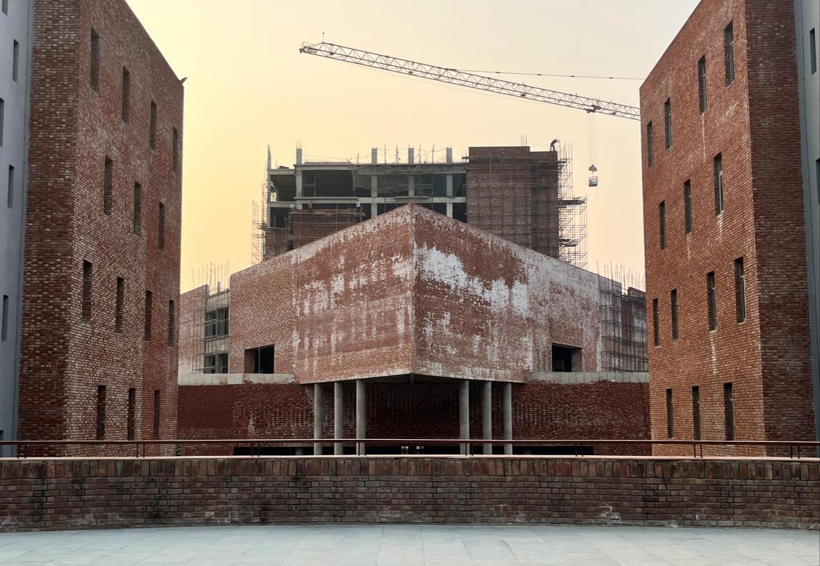
Construction photo 22 June, 2021 - Block 6
Fig. 1
1.2 SITE PROFILE

The site is located within the campus of "University Institute of Management Studies" which is a part of "Chandigarh University". It is a campus of almost 23 acres.
The site is surrounded by various building blocks like Hostel Block, UIAHS 1 and Academic Block

The whole campus is surrounded by green fields and farms.
The site is connected to the main highway Ludhiana –Chandigarh state highway NH05
The site is surrounded by the fields and the near by villages are Gharaun, Hasanpur and Mamupur
 Site plan 2022 Block 6
Fig. 2
Site plan 2023
Chandigarh University
Fig. 3
GHARAUN
HASANPUR
Site plan 2022 Block 6
Fig. 2
Site plan 2023
Chandigarh University
Fig. 3
GHARAUN
HASANPUR
SITE
MAMUPUR
BLOCK 6
1.2.1 SITEANALYSIS
The site is located in south extension of Chandigarh University on NH05 Chandigarh –Ludhiana Highway, Gharaun, Mohali, Punjab, India. The project is located in Gharaun, a peri urban area in the vicinity of Mohali (Punjab) a satellite town of Chandigarh. Chandigarh is a city designed by Le Corbusier located 250 km from New Delhi and is a symbol of modernism in India. Kharar, Mohali, Chandigarh are the nearby cities to the university.

Geographic location
Latitude 31° 45′ 10.35″ N
Longitude 74° 35′ 48.71″ E
Access : By air
Chandigarh university is 29.5 Km via NH 5 & 35.0 Km via NH 205 from the Chandigarh Airport, Mohali.
By rail
(SAS nagar) Mohali Railway Station in Sector 65 is about 25 km from the Chandigarh university. It connects places like New Delhi,Agra, Kanpur, Kolkata, Mumbai, Lucknow with the city.
By road
The most nearby bus stand is in Kharar which is 9.5 km from the campus, then Sector 43, Mohali bus stand which is 20 km, that connects the Punjab and Himachal, Jammu Kashmir with the city and at last Sector 17, Chandigarh bus stand 24 km from the campus which connects the Delhi and Haryana with the city.
During construction photo 2021 -Block 6 Fig. 4
AND CONTEXT IMAGES


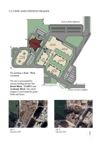
The building is East – West orientated.
The site is surrounded by various building blocks like Hostel Block, UIAHS 1 and Academic Block. The whole campus is surrounded by green fields and farms.

A B C D
1.2.2 SITE
Access from highway Access to new campus
Fig. 5 Site plan 2020
Fig. 6 Site plan 2021


 Photo from Admin Block 4 Walkway, 7 December, 2021 – Fig. 8
View of Block 3 from Main Entrance, 13 August, 2022 – Fig. 10
Double height Main Entrance, 7 December, 2021 – Fig. 9
View of Block 7 from Double Height Semi open seating area, 2 August, 2022 – Fig. 7
Photo from Admin Block 4 Walkway, 7 December, 2021 – Fig. 8
View of Block 3 from Main Entrance, 13 August, 2022 – Fig. 10
Double height Main Entrance, 7 December, 2021 – Fig. 9
View of Block 7 from Double Height Semi open seating area, 2 August, 2022 – Fig. 7


 Fig. 12
View of Block 7, UIAHS 1
Fig. 11
View of Block 3 & 4, Academic Blocks
Fig. 13
View of New Hostel Block
Fig. 12
View of Block 7, UIAHS 1
Fig. 11
View of Block 3 & 4, Academic Blocks
Fig. 13
View of New Hostel Block
1.2.3 CLIMATOLOGY & TOPOGRAPHY


The climate here is mild, and generally warm and temperate. The climate here is a humid subtropical climate which is very hot summers, mild winters, unreliable rainfall.
AVERAGE TEMPERATURES & PRECIPITATION


Precipitation is the lowest in November, with an average of 6 mm | 0.2 inch. Most precipitation falls in July, with an average of 195 mm | 7.7 inch.
WIND SPEED
The monsoon creates steady strong winds from December toApril, and calm winds from June to October.
Sun path diagram
Site plan - Fig. 14
1.2.4 SOCIAL, ECONOMICAND HERITAGE CHARACTER
Chandigarh is the nearest well developed city. It is one of the best experiments in urban planning and modern architecture in the twentieth century in India. Planned by the renowned architect Le Corbusier, have together helped create one of the most livable cities of India.


Chandigarh heritage comprises buildings and precincts of regional or local importance possessing special architectural or aesthetic merit


 Legislative Assembly, Capitol Complex - Fig. 15
Pierre Jeanerette's Museum - Fig. 16
Sukhna Lake - Fig. 17
Gandhi Bhawan - Fig. 18
Government Housing - Fig. 19
Legislative Assembly, Capitol Complex - Fig. 15
Pierre Jeanerette's Museum - Fig. 16
Sukhna Lake - Fig. 17
Gandhi Bhawan - Fig. 18
Government Housing - Fig. 19
2.1ARCHITECT’S CONCEPT
The concept was to club together a number of functions into a single built form to optimize the utilization of both land and resources. The concept and form arose from a simple stacking of the 3 main functions.

3 DIFFERENT VOLUME FOR 3 DIFFERENT FUNCTIONS
From the given site area, the site was divided into 3 different volumes vertical rather than horizontally for reducing ground area.
AMORPHOUS BUILT FORM

By not totally separated the two areas. The connected of walkways are applied in it. The middle space turned in the courtyard on all floor in different orientations .
SEGREGATED ENTRANCES FOR DIFFERENT FUNCTIONS
The entrances from the four sides allowing people in all sides of the community to join creating an active space within the site.

RECEPTION & WAITING AREA
SHOPS
2.2 BUILT FORM VISION MAIN STAIRCASE
REPRESENT APPROACHTO THE BUILDING
SHOPS
The area within the land of site separated into two areas, public and private combining all in the triangular form.
The idea was to create an amorphous built form so as to allow free movement through and through the building creating an incidental interaction space. Also, the multiple entrances ensured the segregation of circulation for different functions.
Another important aspect of the overall building was that there was no actual rear or back side of the building. The central cut out allows for both light and ventilation to penetrate into the lower floors in the center.

OUTDOOR SEATING
MALE TOILETS
ENTRANCE
RECEPTION & WAITING AREA
FEMALE TOILETS
OPEN TO SKY COURTYARD
OUTDOOR SEATING
MAIN STAIRCASE ENTRANCE
SHOP SHOP KITCHEN
SHOP
SHOP KITCHEN
2.3 SPACIAL ZONING


The main entrance for this area is from the side of the building with a reception on the ground floor.
The ground floor and the first floor, which are the lowest triangular blocks, house the student facilities of eating, shopping and daily utilities.

The second floor and the third floor house the library with the main entrance from the grand set of staircases almost starting from the entrance the ground floor..
The upper floors house a guest house for VIP guests and visiting faculties.
2.4 MOVEMENTAND CIRCULATION
Considering mostly on the people that will come in the cafeteria area, the circulation was created to force people in certain directions focusing on the time and ways that people will walk, in order to have different experience in spaces. Therefore, the circulation will cover the whole area according to the masses placement. Circulation need to having viewpoint inside out from the building.


MAIN STAIRCASE
Width – 9 feet 7.5 inches
Riser – 6 inches
Tread – 1 feet
SERVICE/ FIRE STAIRCASE
Width – 5 feet

Riser – 6 inches
Tread – 1 feet
Arrows are the entrances to the building Circulation on ground floor
SUNKEN ROOFS
C’ C
Circulation on upper typical floors SECTION CC’
Vertical Circulation on typical floors
2.5 SUN PATH AND NATURAL VENTILATION


Harvesting daylight from the façade and roof skylights.
The central axis acts as the circulation’s main route and sub divides into sub-routes for reaching the whole space.
E W N S E W N S
2.6 BUILDING BYE LAWS
This building comes under public buildings for functional classification and assembly buildings for occupational classification. Hence safety provisions will be as per the classification as follows.
Minimum
DETAILOF PLAN PROPOSAL
Total built up area - 19678.67 Sq.Ft
No of Storey - (G+ 7 Floors)
Ground Coverage - 20,798 Sq.Ft
Total Covered Area - 94,978 Sq.Ft
Front Setback – 30 feet
Rear Setback – 20 feet
Clear height – 14 feet
Internal courtyard area – 554 sq. ft
Staircase - Width – 9 feet 7.5 inches – Riser – 6 inches – Tread – 1 feet
Lift – 8 feet x 6 feet
Permissible limits
Approach Road 12 M (40’-0”)
Parameter
Minimum
Site Area Upto 2000 sq.m
backs around building
Set back required Front and rear setback Side setback, if left at any point of the building 6 M
ground coverage 40% of the plot area
floor area ratio 1:1.0 1:2.0 or 1:2.5 in case of textile and knitwear Maximum Height of Building No Restriction Minimum Clear Ceiling Height 3.6 M Internal Courtyard Minimum Area 9 sq.m
Set
Minimum
Maximum
Maximum
width 2000 mm
Mandatory
Staircase minimum
Lift
2.7AREAPROGRAM SUMMARY
AREASTATEMENT BLOCK 6

• FAR AREACOVERED ONALL FLOORS/SITE AREA = 94978/ 88481.85
1.07
• PARKING
There is parking provided at the common area for some clusters of blocks in the whole university and not in every block because it wasn’t necessary and it was not on the university’s requirement list
S. NO FLOOR AREA(IN SQ. FT.) 1 GROUND FLOOR 20,798 2 FIRST FLOOR 15,493 3 SECOND FLOOR 16,901 4 THIRD FLOOR 15,903 5 FOURTH FLOOR 6,415 6 FIFTH FLOOR 5,782 7 SIXTH FLOOR 5,782 8 SEVENTH FLOOR 5,782
MUMTY FLOOR 2,122
9
TOTAL 94,978 SQ. FT.
Fig. 20 Site plan 2023
SITE PARKING
3.1 FLOOR PLANS 2.96 10 5.54 Ground Floor Area Distribution Kitchen 3.38% Shops 3.46% Toilets and facilities 4.76% Services 1.1% Vertical circulation 13.1% Horizontal circulation 55.2% Cut outs 2.96% Outdoor seating 10.0% Office area 5.54%


1. DOUBLE HEIGHT ENTRANCE FOR STUDENTS 2. CUT OUT 3. STAIRACSE 4. CENTRAL COURTYARD 5. SHOPS 6. KITCHEN 7. SEATING AREA 8. STORE 9. DOUBLE HEIGHT SEMI OPEN SEATING AREA 10. MOUNDS 11. SERVICE CORRIDOR 12. BANK SPACE 13. DOCUMENTATION CENTRE 14. ENTRY FOR GUESTS 8. STORE 9. DOUBLE HEIGHT SEMI OPEN SEATING AREA 10. MOUNDS 11. SERVICE CORRIDOR 12. BANK SPACE 13. DOCUMENTATION CENTRE 14. ENTRY FOR GUESTS 15. RECEPTION AREA 16. WAITING AREA 17. FACILITIES 18. ELECTRICAL ROOM 19. BACK OFFICE AREA 20. LIFT LOBBY 21. ELEVATOR 22. SERVICE ELEVATOR 23. LUGGAGE CABINET 24. PANTRY
LEGEND 3.38 3.46 4.76 1.1 13.1 55.2
LEGEND
1. BRIDGE
2. CUT OUT ABOVE
3. COURTYARD BELOW
4. STAIRCASE
5. DRINKING WATER AREA
6. BUFFER AREA
7. CUT OUT BELOW
8. DINNING HALL AREA
9. COUNTERS
10. HANDWASH AREA
11. TERRACE GARDEN
12. DOUBLE HEIGHT AREA BELOW

13. LIFT LOBBY
14. ELEVATOR
15. SERVICE
16. KITCHEN AREA
17. TERRRACE FOR KITCHEN SERVICES
5.24
Kitchen 12.7%
Open terrace 4.7%
Hand wash area 1.7%
Vertical circulation 8.7%
Dinning hall/ Horizontal circulation 66.8%
Cutouts 5.24%

12.7 4.7 1.7 8.7 66.8
First Floor Area Distribution
LEGEND
1. SECURITY CHECK
2. BUFFER SPACE
3. RECEPTION AND LOCKERS
4. BOOK ISSUE AREA
5. LIBRARY AREA
6. CUT OUT BELOW
7. COURTYARD BELOW

8. CUT OUT ABOVE
9. TERRACE GARDEN
10. SKYLIGHT
11. STAIRCASE TO UPPER FLOOR
12. STAIRCASE
13. LIFT LOBBY
14. ELEVATOR
15. SERVICE
16. A.H.U ROOMS
17. SPACE FOR LIBRARY STORES AND STAFF AREA
18. TERRACE BELOW
Staff area 7.37%
Services 1.5%
Vertical circulation
15.6%
Library/ Horizontal circulation 53.2%

Cutouts 3.6%
Terrace garden with outdoor seating 18.4%
7.37 1.5 15.6 53.2 3.6 18.4
Second Floor Area Distribution
LEGEND
1. LIBRARY AREA
2. TERRACE GARDEN
3. COURTYARD BELOW
4. CUT OUT ABOVE

5. SKYLIGHT ABOVE
6. STAIRCASE DOWN TO SECOND FLOOOR
7. TERRACE GARDEN BELOW
8. SKYLIGHT BELOW
9. LIFT LOBBY
10. ELEVATOR
11. SERVICE ELEVATOR
12. STAIRCASE
13. A.H.U ROOMS
14. FACILITIES
15. SPACE FOR LIBRARY STORES AND STAFF AREA
16. TERRACE BELOW
Staff area 4.9%
Toilet and facilities
1.3%
Services 2.6%
Vertical circulation
8.4%
Library/ Horizontal circulation 72.4%

Cutouts 4.2%
Terrace gardens 5.8%
4.9 1.3 2.6 8.4 72.4 4.2 5.8
Third FloorArea Distribution
LEGEND
1. LIFT LOBBY
2. GUEST ROOM
3. DINNING HALL
4. BUFFER AREA
5. KITCHEN
6. TERRACE FOR KITCHEN
7. SERVICE STAIRCASE
8. LIFT
9. SERVICE LIFT
10. TERRACE GARDEN
11. SKYLIGHTS
12. STAIRCASE BELOW
13. TERRACE BELOW
14. COURTYARD BELOW

Guest rooms 17.7%

Toilet and facilities 5.4%
Vertical circulation 9.0%
Dinning hall/ Horizontal circulation 36.8%
Kitchen 12.2%
17.7 5.4 9 36.8 12.2
Fourth FloorArea Distribution
LEGEND
1. LIFT LOBBY
2. PRESIDENTIAL SUITE
3. TERRACE FOR PRESIDENTIAL SUITE
4. GUESTS ROOMS
5. TERRACE
6. TERRACE BELOW

7. STORE
8. SERVICE CORRIDOR
9. HOUSEKEEPING
10. TERRACE FOR SERVICES
11. STAIRCASE
12. ELEVATOR
13. SERVICE ELEVATOR
Guest rooms 31.5%
Presidential room 6.1%
Toilets and facilities
11.3%
Terrace 7.8%
Vertical circulation 9.9%
Horizontal circulation
33.0%

31.5 6.1 11.3 7.8 9.9 33
Fifth Floor Area Distribution
3.2 ELEVATIONS
ELEVATION A FRONT ELEVATION
ELEVATION B L.H.S ELEVATION
ELEVATION C REAR ELEVATION


3.3
SECTIONS
SECTION AA’
A A’ B B’
SECTION BB’
3.4 RENDERS VS SITE


 Aerial view – Fig. 21
Outdoor seating - Fig. 22
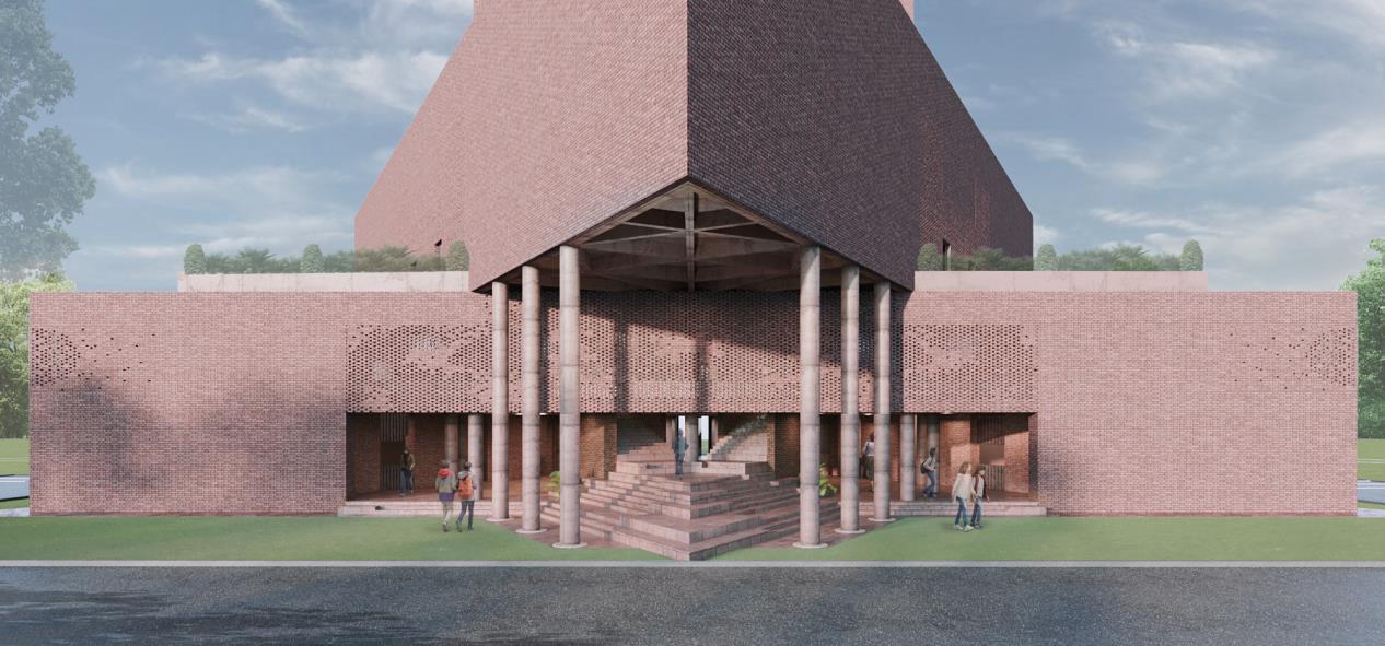
Front View - Fig. 23
Left Side View - Fig. 24
Aerial view – Fig. 21
Outdoor seating - Fig. 22
Front View - Fig. 23
Left Side View - Fig. 24

 Fig. 26
FRONT VIEW
Fig. 25
Fig. 26
FRONT VIEW
Fig. 25

 Fig. 28
REAR VIEW
Fig. 27
LEFT SIDE VIEW
Fig. 28
REAR VIEW
Fig. 27
LEFT SIDE VIEW

 Fig. 30
RIGHT SIDE VIEW
Fig. 29
Fig. 30
RIGHT SIDE VIEW
Fig. 29
RENDERS OF INTERIORS


 Fig. 31
Fig. 32
Fig. 33
Fig. 34
Fig. 35
Fig. 31
Fig. 32
Fig. 33
Fig. 34
Fig. 35
Central courtyard


Site pics from 2020 – present
 Fig. 36
Fig. 38
Fig. 37
Fig. 36
Fig. 38
Fig. 37
LIBRARY RENDERS


 Fig. 39
Fig. 40
Fig. 41
Fig. 39
Fig. 40
Fig. 41
3.5ARCHITECTURAL ELEMENTS


Cantilever at entrance Site pics from 2020 - present
 Fig. 42
Fig. 43
Fig. 44
Fig. 45
Fig. 46
Fig. 42
Fig. 43
Fig. 44
Fig. 45
Fig. 46
Some interior skylights and brick jali


Site pics from 2020 - present
 Fig. 47
Fig. 48
Fig. 49
Fig. 50
Fig. 47
Fig. 48
Fig. 49
Fig. 50
Entrance foyer & triangular planter with outdoor seating Site pics from 2020 - present


 Fig. 51
Fig. 52
Fig. 53
Fig. 51
Fig. 52
Fig. 53
THE END