Introduction
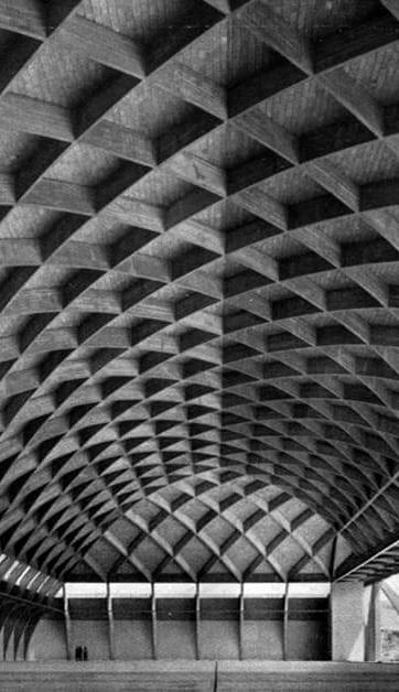
There are various light weight roofing structures, materials and techniques in the construction field. This study about the ferrocement and the material based on ferrocement and its applications.
1. FERROCEMENT
Ferrocement can be considered as a type of thin-walled reinforced concrete construction in which small-diameter wire meshes are used uniformly throughout the cross section instead of discretely placed reinforcing bars and in which Portland cement mortar is used instead of concrete. In ferrocement, wire-meshes are filled in with cement mortar.

Wire mesh
Cement mortar
Inner layer of plaster
Structural support or formwork to support the wire mesh
1.1. Basic Methodology of forming Ferrocement members
A ferrocement structure is formed by fabricating the mesh reinforcement to the shape and size of the structure first and then mortared and cured. Method of forming a ferrocement element is as follows:
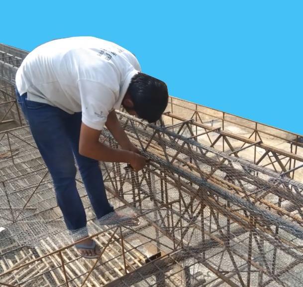
Welding skeletal steel framework.
A skeleton of steel bars is welded to the exact geometrical shape and size of the structure. This provides a rigid framework of the exact shape and size with correct line and level.

Tying mesh reinforcement tightly over it to form cage.
Weld mesh and fine wire chicken mesh is tied over this welded skeleton by stretching and tying technique. ‘Tightly tying meshes’ is the key point in ferrocement construction.
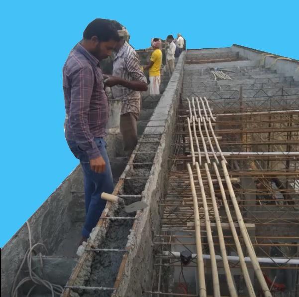
Impregnating the mesh cage with rich cement mortar, finishing and curing.

The stiff cement mortar is filled in the mesh layers by press fill method. In press fill method, the mortar is to be pressed inside the meshes from both the sides. All these steps in construction are to be followed in sequence. On large size constructions, one can work simultaneously on all the three operations.
1.2. Advantages of Ferrocement
Ferrocement has following basic advantages over RCC
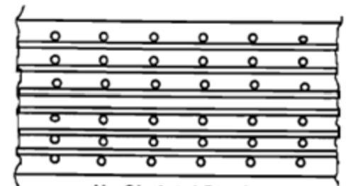
1.2.1. Increase in bond strength:
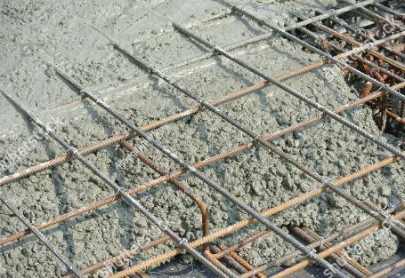
The transfer of load from steel to concrete and vice versa takes place through bond between the two materials. The bond depends upon the bond-stress of concrete and the area of contact between the steel and concrete. Bond stress of concrete depends upon the grade of concrete. It is hardly 6 kg/cm2 for M15 concrete. The bond can be substantially increased if the contact area between steel and mortar is increased. For Ferrocement, it is achieved by use of small diameter wires and mortar.
Difference in the Reinforcement RCC and Ferrocement mesh
1.2.2.
Bond area increase:
Increase in bond area will result in more adhesion between steel and mortar, making it behave more like a homogeneous material and which has become very strong in tension due to increase in bond.
1.2.3. Dispersion of steel wires:
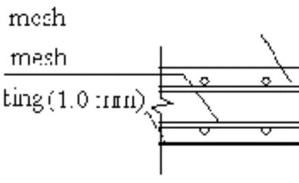
Ferrocement is formed by tying together a number of layers of continuous wire meshes. Volume of steel percentage is very large, may be up to 8 percent. Also, the mortar cover over the meshes is hardly 3 to 5 mm. Hence, throughout the body of the composite, the wire reinforcement is fully dispersed. This leads Ferrocement to become more homogeneous. It results in improving the properties of Ferrocement in tension, flexure, impact resistance and crack resistance. Mesh
1.2.4. Crack control:
Meshes are fully bonded to mortar and spaced very near to the surface of Ferrocement. Such closely spaced fine wires, very near to the surface of Ferrocement, act as crack arrestors.
1.2.5. Equal strength in both directions:
The continuity and placement of equal mesh reinforcement in both directions make Ferrocement to achieve equal strength in two directions and to become strong in resisting diagonal tensions due to shear.
1.2.6. Containment of mortar matrix in mesh layers:
In Ferrocement, layers of wire mesh tightly tied together are impregnated with cement mortar. The matrix is held by the meshes in between and is contained by them.
1.2.7 Formless construction:
Tightly tied meshes in ferrocement can hold wet cement mortar when it is press filled in them. The consistency of cement mortar is very thick with very low water cement ratio. It won’t come out of the meshes. Thus, casting of Ferrocement does not need any formwork or shuttering. The other advantage of this aspect is no honeycombing will occur in press filling, as the mortaring is done in front of your eyes. If the mesh is tied loosely or water cement ratio is not maintained to thick consistency or over-sanding is done, the mortar will flow down and will not be held by the meshes.
1.2.8. Strength through shape:
Ferro Crete structures are thin walled and may be hardly 25 to 50 mm in thickness. Hence, to take care of slenderness and buckling, Ferrocement is shaped in different forms to achieve its strength.
1.2.9. Lightweight, homogeneous and versatile material:
Ferrocement structures have high equal strength in both directions. It can be molded in any shape and size. Ferrocement is homogeneous, easy to work and can be made available in thin sections.
1.2.10. High strength to weight ratio:
Being a thin-walled structure of high strength, strength to weight ratios in tension and compression of ferrocement are very high. Hence thin sections can take higher loads.
Ferrocement composite has different features than Reinforced cement concrete. Features like thickness of products, matrix used in products, reinforcement, strength, structural behavior etc. on which they are differentiated, is given in table 1.1

S. No Features Reinforced Cement Concrete Ferrocement

1 Thickness Minimum 75mm Thin walled, 25 to 50 mm.
2 Matrix material Cement concrete Rich cement mortar
3 Reinforcement Steel bars > 6mm diameter Spaced distance apart Continuous fine wire mesh dispersed throughout the body of the structure.
4 Strength Weak in tension, bond and shear High tensile strength, superior bond and shear strength.
5 Tensile strength 4-6 kg/cm2 80-90 kg/cm2
6 Strength to Weight Ratio 15 to 50 45 to 90
7 Casting process Formwork and shuttering are quite essential. Due to forms honeycombing is likely to occur.
Tightly tied wire-meshes act as supporting mortar casting. Filling is dense and compact, no honeycombing.
8 Composition Heterogeneous Nearly Homogeneous
9 Gain of strength Due to size, shape and reinforcement Due to shape of the structure
10 Structural Behavior Rigid Non rigid
2.MATERIALS
2.1Materials used in ferrocement structures
a) Skeletal steel in the form of angles, steel bars, welded wire fabrics or pipes.
b) Steel wire meshes for forming cages.
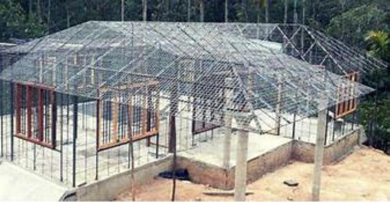
c) Rich cement mortar, as matrix in form of micro-concrete. All these three raw materials are those which are commonly used in practice in construction of conventional buildings.
2.2. Skeletal steel
2.2.1. In the form of steel bars:
Skeletal steel as the name implies is generally used to give basic shape and size to the structure. If used only to give the form to the structure, the steel rods may be spaced wide apart, say even up to 500 mm. When they are not treated as structural reinforcement, they also act as spacers to the layers of meshes. In highly stressed structures, where the skeletal steel acts also as reinforcement, their spacing will be as per the structural design of the structure. Steel bars of 4 to 10 mm dia. are generally used. Sometimes angle framework may be used to support the structure.
2.2.2. In form of welded bar fabric:
Welded bar fabric may be used as skeletal steel for Ferrocement panels of large size. A wide range of permutations of bar sizes and spacings is available, from which the required design can be chosen. Welded bar fabric is available for bar diameters from 4 to 10mm, with spacing of bars from 50 X 50 to 300 X 300 mm square or rectangular in shape.
2.2.3. Specifications Reference:
Steel bars to be used should be according to I. S. Specifications as follows:
1 Mild steel bars confirming to IS-432(Part I) 1982,
2 Hard drawn steel wires confirming to IS-432 (Part II) 1982 and
3 Hard drawn steel wire mesh fabric IS 1566-1982.

2.2.4. Practical hints in selecting the skeletal steel:
1 The steel area particularly at the location of welding of cross bars should not be more than 50% of the cross-sectional area of ferrocement. It is observed that when large diameter steel bars are used or angles are used, temperature cracks are formed along the line of steel bars.
2 Bars of 6- or 8-mm diameter could be used for small structures, to maintain the rigidity of framework, the edge-bars may be 8mm dia. tor-steel, while the other bars may be 6mm dia. mild steel.
Welded joints of cross bars
< 50 % of ferrocement
Image
The following table 2 and table 3 will be useful in placing an order in the market for steel bars:
Table 2 Weights and lengths of steel bars.
Table 3 Weights of skeletal bars per m2 of panel for various spacing of bars (Calculation based on a panel size 3.0m X 3.0m)
2.3. Steel wire meshes
Fine wire mesh reinforcement is the basic element of ferrocement, it controls the specific surface, which is an important factor in design. The number of layers of meshes, decide the thickness of the composite. Four basic types of meshes are in use.
a. Weld mesh
b. Fine wire mesh (woven square mesh/interlocked hexagonal wire mesh/Chicken wire mesh)
c. Expanded metal.
d. Crimped wire mesh.
2.3.1 Weld mesh
Welded wire mesh of rectangular pattern as shown in Img.12 is formed by aligning wires perpendicularly and welding them at their intersections. Weld mesh is tied on skeletal steel
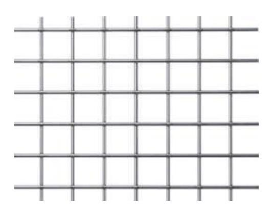
framework and it provides a base for tying fine wire meshes on it. Its surface area is considered in calculating the specific surface of the composite. Weld mesh is designated by the spacing of wires or the size of openings, followed by the gauge of the wire in longitudinal and transverse directions. Thus a 100 mm x 100 mm x 12 g x12 g means a weld mesh of opening size of 100 mm x 100 mm and wire gauge used in longitudinal and transverse directions are 12 gauge. Weld meshes generally used in ferrocement structures are having opening sizes in mm as 25 x 25, 50 x 50,75 x 75, 100 x 100, and 150 x 150. The wire gauges may vary from 10 to 16. Rolls of weld meshes are available in widths of 900, 1200 and 1500 mm and in lengths of 15 m or 30 m.
2.3.1.1 Practical hints in using weld mesh:
While using weld mesh, the following precautions should be taken: 1) weld mesh should be cut only by a weld mesh cutter and not by chisel and hammer.
2) weld mesh is available in form of rolls in market. When they are opened the weld mesh comes out in bent and curved form. It needs to be straightened out. Also, when the roll is opened, it comes out with springing action, which may cause injury to the worker. So, the roll should be opened in the reverse direction of its curvature.
3) While straightening the weld mesh, it should be hammered out with a light hammer. Do not hammer at the joints, the weld may get opened. Hammer the wires in between the welds in both directions.
4) It is better to weld the skeleton first and then tie weld mesh and chicken mesh over it.
5) While cutting the weld mesh, it should not be cut close to the weld, because there is a possibility of opening of all the welds in the line of welding and the wire strands may get separated. The cut should be taken at about half a centimeter away from the weld.
6) Along the length of the weld mesh rolls, at the top and bottom edges, small protruding of wire is left by the manufacturer. They should not be cut. These protruding are useful while tying chicken mesh on it.
2.3.2 Fine wire meshes /interlocked hexagonal wire mesh/Chicken wire mesh) Image 13 Chicken mesh
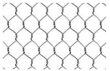


1) Woven square meshes are formed by weaving them on wire weaving machines and are having rectangular openings of size 13 mm X 13 mm, 19 mm X 19 mm, 25 mm X 25 mm, in them. Wire gauges used are 18 to 22 gauges. Generally, they are ungalvanized. Rolls of 15 m or 30 m in length and widths of 900 mm or 1200 mm are available in market.
2) When square wire mesh is cut the ends of wires should be folded back immediately. Otherwise, the mesh wires get loosened and separated.
3) Interlocked woven hexagonal wire meshes (also called chicken mesh) While weaving they are also interlocked due to which, they take a hexagonal shape. Their interconnections are not rigid. Chicken mesh is available in galvanized form as shown in Img 13, and in sizes of openings of 13 mm X 13 mm, 19 mm X 19 mm and 25 mm X 25 mm. Wire gauges from 20 to 26 are in use. Rolls of chicken mesh of 15 m or 30 m lengths and 900 mm, 1200 mm or 1500 mm widths are available in market.
2.3.2.1 Practical hints in using chicken mesh:
1) Chicken meshes have an advantage that they can be stretched and tightly tied over the weld mesh. A width of 900 mm of the mesh may get extended by about 50mm to 75mm.
2) Wires being interlocked in form of hexagonal net, geometrically it is not a rigid framework. Hence, its stretching in both directions is possible. While stretching and tying, care should be taken that the hexagonal shape of the mesh is maintained, by applying
equal stretch in both directions. Square meshes cannot be stretched and tied tightly and so use of chicken mesh as fine wire reinforcement in ferrocement is recommended.
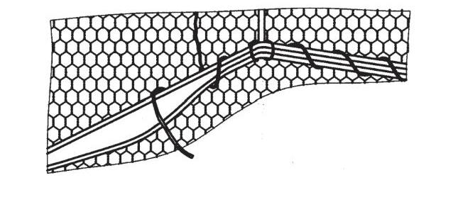
3) Along both the edges of the mesh, a straight wire is provided for convenience of weaving. At the time of using, these straight wires should be cut at some intervals. Otherwise, they prevent stretching of the mesh by restraining their edges. This will result in bulging out of the mesh at its edges.

2.3.3. Expanded metal:
Image 14 Expanded metal mesh
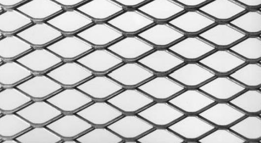

Expanded metal lath (XPM) as shown in Img 14 is formed by slitting thin gauged steel sheets and then expanding them in directions perpendicular to the slits. This expanded thin sheet takes the shape of a diamond. Among all the fine wire meshes, it is expanded metal, whose shape, size and structural properties can be assured exactly. Hence in many research projects, expanded metal lath is used and properties of ferrocement are established with it. XPM mesh is designated by short diagonal (short way of mesh
SWM), Long diagonal (long way of mesh –LWM) of the diamond, width of the strand and
the thickness of the plate. Thus, 100 X 250 X 3.25 X 10g, XPM sheet means, 100mm SWM, 250mm LWM, 3.25mm strand thickness and the gauge of the plate is 10. 11 XPM sheets of various sizes are available in market. XPM sheets are very hard to cut and when a number of layers are to be used, it is very difficult to force mortar in all the interstices. Orientation of XPM mesh plays very important role in determining the tensile strength of ferrocement specimen. While forming XPM, by stretching the slotted sheet, the intersections of the strands get twisted and become weak in tension.

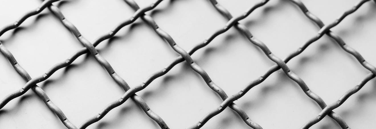
The matrix used in ferrocement primarily consists of mortar or micro concrete with hydraulic cement as binder, sand as fine aggregate and water. Normally the aggregate consists of well graded fine sand passing IS 2.36 mm sieve. If permitted by the size of the mesh and the distance between the mesh layers, small size coarse aggregate may be added to the sand. The mortar matrix usually comprises of more than, 90 percent of the ferrocement volume, and hence has a great influence on the behavior of the final product. Hence a great care should be exercised in choosing the constituent materials and in mixing and placing them.
2.4.1 Cement:
The cement should be fresh, of uniform consistency and free from lumps and foreign matter. It should be stored under dry conditions for as short duration as possible. Types of cement are ordinary Portland cement of various grades, rapid hardening cement, sulphate-resisting cement, white and colored cement and pozzolana cement. The choice of any particular cement depends upon the site conditions. Generally Ordinary Portland Cement of 43 or 53 grades is used in ferrocement. In coastal areas or for structures exposed to sea water or acidic industrial wastes sulphate resisting cements are recommended. If sulphate-resisting cements or admixtures are not available, rich cement mortar should be used and later the structure should be coated. Cement content in ferrocement is higher than in conventional reinforced concrete. For Ordinary Portland cement IS 8112: 2015 and IS 12269: 2015 should be referred.
2.4.2 Aggregates: Sand
2.4.2.1 Natural Sand

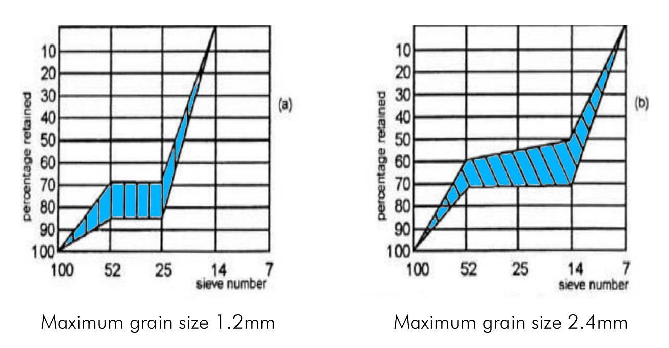
Well graded and washed river sand passing 2.36mm IS sieve is most commonly used as fine aggregate in ferrocement. The maximum size of aggregate depends upon the size of mesh openings and the spacing between the layers of mesh. For 13mm mesh openings, 1/4th its opening size, that is less than 3.25 mm, should be the maximum size of the fine aggregate. For proper gradation fineness modulus of sand should be between 2.4 to 2.5 for maximum grain size of 1.18mm and it should be 2.9 to 3.0 for maximum grain size of 2.36 mm. As shown in fig 3.5, proper control over the grain size and fineness modulus will result in the least water requirement, with better workability and higher strength. Grading of sand, with cement of 43 grade and aggregate as crushed sand confirming to IS 383-1970 is given in table
3.4.2.2 Crushed sand or manufactured sand

Crushed sand is a good substitute for natural sands. It is manufactured from quarried rock, by bringing down its particle size in the range of 4.75mm to 150 microns. Crushed sand is quite different than stone dust, which is a waste from stone crushers. Crushed sand has two important features; one is its gradation and the second is its particle size. Crushed sands are successfully used for various grades of concrete from M15 to M40.
2.4.3 Water
The mixing water should be fresh, clean and potable. It should be free from organic matter, silt, oil, sugar, chlorides and acidic materials. The value of pH should be close to 7.0. The salt water is not acceptable but chlorinated drinking water will do.
2.4.4 Admixtures
Chemical admixtures in ferrocement serve four purposes:
a) Water reduction which increases the strength and reduces the permeability. It can be achieved by using super plasticizers.
b) Waterproofing compounds may be used to get watertight structures.
c) Air entraining agents increase the resistance to freezing and thawing.
d) Suppression of galvanic action between galvanized steel and cement is achieved by using Chromium trioxide approximately 300 parts per million, in mixing water.
2.4.5 Proportioning of cement mortar
Normally rich cement mortars of mix proportions of (1:1.5) to (1:4) by volume are used in ferrocement. When sand content is increased, its water requirement goes up to maintain the same workability. To obtain strong, dense and mortars of such a consistency, which can easily penetrate the layers of meshes, trial mixes should be taken. Fineness modulus of the sand, water cement ratio and the sand cement ratio for the mix should be determined and used. Due to dispersion of wires throughout the body of ferrocement, problem of shrinkage is not there. Depending upon the method of application of mortar, its plasticity plays an important role. Normally the slump of cement mortars should not exceed 50 mm to provide stiff mortar mix, which can penetrate meshes. For most applications, the 28 days compressive strength of moist cured cement mortars should not be less than 35 MPa. Generally, the mix proportions are specified by their weight but on small jobs mixes are made on volume basis. The bulging effects of moist sands must be allowed for, when the mixes are based on volume basis.
2.4.6 Practical hints for proportioning and mixing of cement mortars.
a) A simple field test to find out stiff consistency of mortar is to form a ball of the mortar in hand and when it is tossed up, it should retain its shape.
b) Another practical test is, when the trowel is inserted in the heap of the mix, it should stand erect.
c) To check silt content in sand, mix it with water, put it in a glass jar, shake it and allow it to settle. The thickness of the layer of the silt collected over sand will show percentage silt content in sand approximately.
d) Another simple test to check silt content, is to rub the wet sand on the palms of hand, the hands will get spoiled if the silt content is high.
e) One medium sized ghamela when filled in to its brim, with level surface, contains about 6 to 8 liters of sand.
f) A good homogeneous cement mortar mix has uniform gray cement-color and smooth texture. All sand particles are fully covered with cement paste.
g) Compressive strength of ferrocement is the compressive strength of matrix. Hence extreme care should be taken while proportioning and mixing of mortar. If higher strengths are desired, steel fibers may be added or polymer mortars may be used.
2.4.7 Guidance of proportion of
mortar
A quick guide for various mortar mixes by volume measure and by weight is given in tables 5 and 6
Table 5 Cement Mortar mix by volume Dry mix of mortar = 1.33 x (wet mortar mix) (Quantities per m3 of wet mortar)
2.4.8
Mortar filling is done by two ways
After making the skeleton of bars and tightly fitting of meshes, it is checked that there is movement of the meshes. The structure shall be strong enough for any shocks and vibrations. The mortar of cement to sand in 1:2 or 1:3 proportions is preferred. The water content shall be as less as possible. The test is that the mortar shall not flow but a ball of mortar can be prepared. The water to cement ratio normally is 0.35 to 0.40. The thick mortar is then pressed in the gaps of the meshes by using plate trowels. Two persons are required for pressing it from both sides. No air shall remain in the mortar. After 3 hours, the filled mortar becomes hard enough. The same surface can be plastered smooth after 1 day. This method is useful when both surfaces are available for press filling.

2.4.8.2 Press Spray method
Image 17 Press spray method
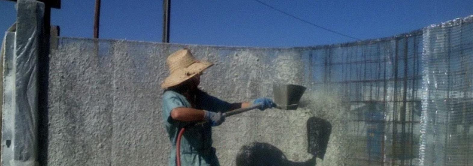
When only one surface is open, pressing of mortar from one side is also possible, provided other surface is closed by fixed surface of rock or wall as shown in Img 17. For mass scale work sprayers of mortar are used. Water to cement ratio for such mortar is 0.50 to 0.60. The mortar is sprayed with pressure and it sticks in the gaps of meshes. The work of spraying is much faster than that done manually.
2.4.9 Job requirements of skilled workers:
Skilled workers required are welder for fabricating the skeleton, fitter to tie mesh and mason for mortaring.
Welder: For welding skeletons, a welder with knowledge of spot welding and line welding is sufficient. No special hightech welding is involved and hence any ordinary welder will serve the purpose.
Fitter:
For tying the mesh, any fitter, with a training of few hours, can undertake the job.
Mason: For mortaring, the mason needs training in press filling mortar in the mesh layers. Generally, the masons are trained to plaster the walls by splashing mortar on them. It should be emphatically stressed, that mortaring of ferrocene is not plastering, but it is impregnating the meshes with mortar. Any mason can pick up this skill within no time. For finishing the surfaces, a good plasterer will be required.
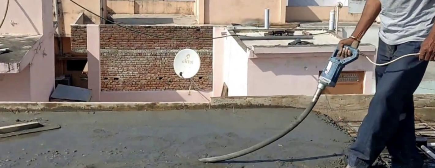
As the ferro Crete is thin walled, use of a needle vibrator is of no use. A wood orbital sander can be satisfactorily used for this purpose. It is very handy and is just like an electric iron used for pressing clothes. The sander has got a handle and a vibrating plate
and it can be moved over the mortar to vibrate and compact it to its full depth. This orbital sander is very convenient to compact mortar in thin layers.

2.6 Curing
Curing of the ferrocement walls and components is done as specified for cement concrete. The hardening process is completed in 21 days. However, as the thickness is less, cracks due to shrinkage may develop. For this, curing has to be properly observed. The covering of surface by wet cotton is always recommended. The curing plays a very important role in ferro Crete construction, as the structures are very thin walled and likely to get dried very quickly, particularly in summer season of the tropical countries. In curing the structures like water tanks or containment vessels, they are filled in completely with water and cured for 21 days. For the first 8 to 10 days the mortar is seen wet and saturated with water. As it gets hardened with time, outer surface of the tank becomes bone-dry and indicates that the tank is getting cured properly. The curing of other ferro Crete structures can be done using wet gunny bags. For precast ferro Crete items, sprinklers or steam curing techniques may be used.
3. EQUIPMENT AND TOOLS
3.1 Tools, plants and machinery
After consideration of the materials required for building a ferrocement structure, we have to consider various tools and equipment required for construction. The equipment
required to fabricate and cast ferro Crete structures is given below. Generally, fabrication welding and tying of ferro Crete cage is undertaken in factories. The work left at site is only mortaring, finishing and curing. For pre-casting of ferro Crete products separate plants and machinery are required.
3.2 For fabrication and welding of bar skeleton:
Image 18 Tools
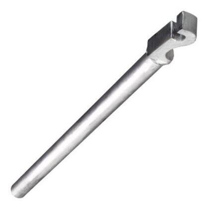
For cutting, straightening and bending of bars tools of a fitter are adequate as shown in Img 18. For small jobs a shearing chisel and a heavy hammer will serve the purpose but for large scale works, shear cutting machine should be preferred.
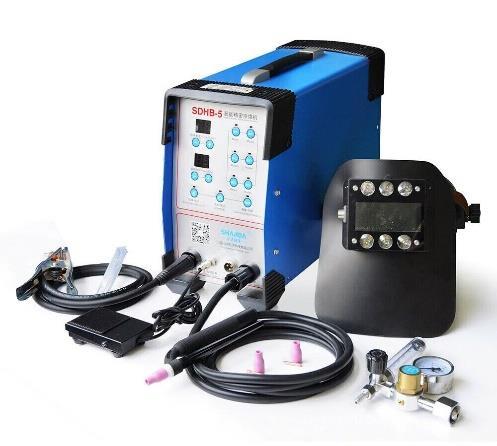
A single-phase welding transformer will suffice the need of spot and line welding of bar skeleton. All the welder’s tools with safety measures will be required.
3.3. For tying mesh on bar skeleton
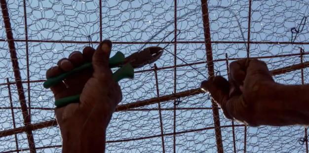
For cutting meshes, weld mesh cutters and chicken mesh cutters are used as shown in Img 19. For binding the mesh to bars, pliers and hooks are required. For stretching and tightening the mesh, mesh pullers in form of screw drivers are preferred as shown in Img 20. Stretching and tying mesh tightly is a very monotonous, tedious and time-consuming job. It needs meticulous workers to finish it properly.

3.4
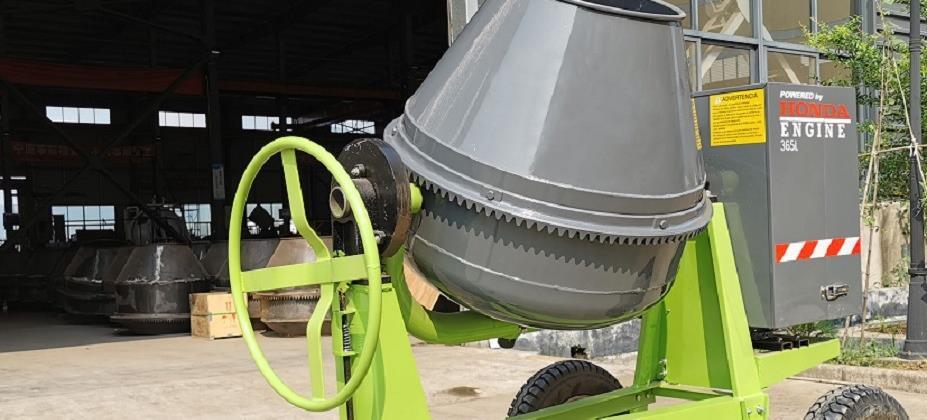
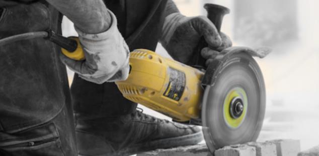
On small jobs, hand mixing is done, and all the tools of a mason are used for it. For major jobs, a mortar mixer is preferred. A mortar mixer with spiral blades or paddles inside a stationary drum or a pan type of mixer can be used. A rotating drum mixer with fins fixed to the sides is not recommended. Mortar should be mixed in batches, in such a way that the mortar mixed in a batch should be used within an hour of its mixing.

Retempering of the mortar should be prohibited.
3.5. For mortaring the structure

As explained earlier, mortaring does not mean plastering the meshes. The mortar is to be pressed inside the gaps of meshes from both the sides. In hand working, plate trowels are used in addition to all the tools required by a mason as shown in fig. 4.5. A vibropress is also developed by some professionals which assure full penetration of the mortar in the mesh layers and results in dense mortar filling. For large works guniting may be adhered to, with complete guniting system as shown in fig 4.6. A small size brush coater may be developed and tried as an alternative.

3.6.
For handling ferro Crete items:
For handling, hoisting and erection of small size articles like water tanks, a chain pulley block with a hoisting pole is used as shown in Img 23. A small capacity crane or hydra may be used to handle precast products. The hooks are to be attached to the precast component only at specified location. Otherwise, cracks may develop.

4. TESTING OF MATERIALS (FIELD TESTS)
4.1 Tests of raw materials in forming ferro Crete structures
a. Test of skeletal steel in the form of angles, steel bars, welded wire fabrics or pipes.
b. Test of steel wire meshes for forming cages.
c. Test of rich cement mortar, as matrix in the form of micro-concrete. All these three raw materials are those which are commonly used in practice in construction of conventional buildings. They are easily available even at village level.
4.2. Tests of skeletal steel in the form of steel bars
Skeletal steel as the name implies is generally used to give basic shape and size to the structure. Steel bars of 4 to 10 mm dia. are generally used as shown in fig. 5.1. Sometimes angle framework may be used to support the structure.
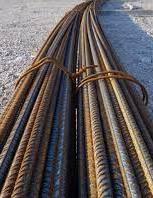
Steel bars and wire meshes to be used should be according to I. S. Specifications as follows:
Mild steel bars: IS-432(Part I) 1982
Hard drawn steel wire mesh fabric: IS 1566-1982
Fine wire meshes and welded mesh: IS 16014: 2012
Mild steel wire confirming: IS 280-1978
Whenever a rebar under a high temp is quenched under controlled conditions and cooled in air subsequently, due to metallurgical transformation, two distinct phases (shades) show out. Tempered marten site in the form of a ring with definite width forms the outer case (ring), whereas the inner core remains pearlite / ferrite. The outer case (ring) and inner core are distinctly visible, when the cross-section of rebar is etched.
4.2.1. The Field Test – test procedure.
Following are the steps for carrying out the test
1. Cut ‘small length samples’ from a few randomly selected TMT rebars of any lot, preferably in a cutting machine, if not, by hack-saw cutting.
2. Cross-sections of test samples shall be mirror finished with any suitable polishing device. An ideal polishing device is a unit with rpm of about 3000, where in emery sheet
can be mounted on the rotating circular disc. Polishing of cross-sections shall be done for at least about 10 minutes.
3. The cross section shall be smeared (etched) with drops of ‘Nitrol Solution’. It is nothing but a synthesis of ‘10 % of Concentrated Nitric Acid’ and ‘90 % of Ethyl Alcohol’. Soon after etching, two distinct phases (Shades) with uniform thickness are clearly visible on the c/s, if the rebars are ‘Genuine TMT Rebars’. If the two phases are not distinct, the rebars are either ‘Substandard’ or ‘Fake’ TMT rebars. Note: It is essential that the c/s need to be examined soon after etching. In case of delay, etching has to be redone.
4.3. Tests of Cement
The cement should be fresh, of uniform consistency and free from lumps and foreign matter. Types of cement are ordinary Portland cement of various grades, rapid hardening cement, sulphate- resisting cement, white and colored cement and pozzolana cement. The choice of any particular cement depends upon the site conditions. Generally ordinary Portland cement of 43 or 53 grade is used in ferro Crete. In coastal areas or for structures exposed to sea water, or acidic industrial wastes sulphate resisting cements are recommended. Pozzolana cement is generally not recommended. For Ordinary Portland cement IS 269:2015 – (33 grade Ordinary Portland cement) should be referred.
4.3.1. Some hints to test the cement in field
1. Date of Manufacturing: As the strength of cement reduces with age, the date of manufacturing of cement bags should be checked.
2. Cement Color: The color of cement should be uniform. It should be typical cement color i.e., gray color with a light greenish shade.
3. Whether Hard Lumps are Formed: Cement should be free from hard lumps. Such lumps are formed by the absorption of moisture from the atmosphere.
4. Temperature Inside Cement Bag: If the hand is plunged into a bag of cement, it should be cool inside the cement bag. If hydration reaction takes place inside the bag, it will become warm.
5. Smoothness Test: When cement is touched or rubbed in between fingers, it should give a smooth feeling. If it felt rough, it indicates adulteration with sand.
6. Water Sinking Test: If a small quantity of cement is thrown into the water, it should float some time before finally sinking.
7. The smell of Cement Paste: A thin paste of cement with water should feel sticky between the fingers. If the cement contains too much-pounded clay and silt as an adulterant, the paste will give an earthy smell.
8. Glass Plate Test: A thick paste of cement with water is made on a piece of a glass plate and it is kept under water for 24 hours. It should set and not crack.
9. Block Test: A 25 mm × 25 mm × 200 mm (1” ×1” ×8”) block of cement with water is made. The block is then immersed under water for three days. After removing, it is supported 150 mm apart and a weight of 15 kg uniformly placed over it. If it shows no sign of failure, the cement is good.
4.4 Tests of aggregates
Well graded and washed river sand passing 2.36 mm IS sieve is most commonly used as fine aggregate in ferro Crete. Grading of sand, with cement of 43 grade and aggregate as crushed sand confirming to IS 383-1970 (table 7) is given in table below.
The fine aggregate should be clean, free from organic matter and relatively free from clay and silt. Hard, strong and sharp silica will give strong mortar, while rounded grains of river sand will result in smooth mortar finishes. IS 383-1970 for coarse and fine aggregates from natural sources should be referred to for specifications of natural sands.
4.4.1 How to check quality of sand on field (Field Test on Sand)
1. Take a glass of water and add some quantity of sand in it. Then shake it vigorously and allow it to settle. If clay is present in sand, it will form a distinct layer at the top of sand.
2. In order to detect presence of organic impurities in sand, add sand to the solution of sodium hydroxide or caustic soda and then stir it. If color of solution changes to brown, it indicates the presence of organic impurities.
3. Take a pinch of sand and taste it. If tasted salty then there exists some salt in sand.
4. Take sand and rub it against the fingers. If fingers are stained, it indicates that sand contains earthy matter.
5. The color of sand will indicate the purity of sand. The size and sharpness of grains may be examined by touching and observing visually.
6. For knowing fineness, durability, void ratio the sand should be examined by mechanical analysis.
5.5 Crushed sand or manufactured sand:
Crushed sand is a good substitute for natural sands. It is manufactured from quarried rock, by bringing down its particle size in the range of 4.75 mm to 150 microns
Crushed sand is quite different than stone dust, which is a waste from stone crushers. Crushed sand has two important features; one is its gradation and the second is its particle size. Tests on natural and crushed sand are done by using same IS 383:1970.
Compared to natural sands, the crushed sands have the following special features:
a. Fines passing 150-micron sieve are restricted. The deleterious materials like clays, silts, inorganic and organic salts contained in natural sands affect the strength and durability of concrete. They also cause cracking and discoloring to the finished plaster surface.
b. The basic composition of particle sizes of natural sands hardly confirms with the gradation desired in the mix design. In crushed sands, different particle sizes are available which can be blended to the desired gradation curve.
c. The spheroidal shape of particles of natural sand offers less surface area for the cement to cover, as compared to the cuboidal shape of the crushed sand. Hence cement consumption is more in crushed sand. d. Natural sand needs sieving. The sand available in market contains 15 to 25 % oversize particles which are of no use at site.
e. To remove clay, silt and deleterious matter natural sand needs washing. f. The fines in crushed sands, passing 75 microns, are within limit of 20 % as specified in IS-383-1970. This fraction results in efficient aggregate packing and denser concrete mix. This increased efficiency in void filling in ultra-fine range of cement paste, closes the capillaries and decrease permeability of concrete.
5.6 Water
The mixing water should be fresh, clean and potable. It should be free from organic matter, silt, oil, sugar, chlorides and acidic materials. Water should have Ph more than
or equal to 7.0. Salty water is not acceptable but chlorinated drinking water will do. Presence of salt in water such as chlorides reduces initial strength of concrete and causes rusting problem in steel used in construction. Therefore, testing of construction water is very essential.
5. APPLICATION OF FERROCEMENT IN ROOFING
Roofing: -
flat roof with channel sections, sloping roofs. Shaped roofs like folded plates, cylindrical shells, domes, pagoda, vaults, umbrella, pyramidal, conical, corrugated catenary, gabled and hipped, thermally insulated, hollow floors with grid beams hidden inside forming box sectioned floors.
5.1. Precast Ferrocement materials
5.1.1. Ferrocement Channel Roof
5.1.1.1. Concept
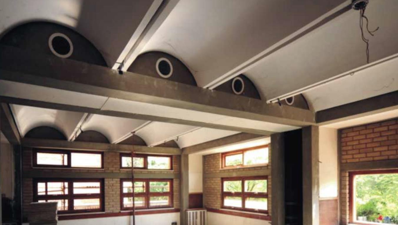
The building system uses pre-cast ferrocement roofing channels of a segmental arch profile which are placed adjacent to each other and spanning over two supports. After partly filling the valley between channels with concrete, the channels form an idealized Tbeam and are able to carry the load of a roof / floor. Ferrocement comprises of a uniform distribution of reinforcement by use of chicken wire mesh and welded mesh encapsulated in rich cement mortar, thereby achieving significant reduction in both steel reinforcement and dead weight of roof. This composition provides a more uniform distribution of strength as compared to RCC.
5.1.1.2. Resources
Table 9 Material and labor requirement for construction of a FC channel roof of size 12’ x15’
5.1.1.3. Components
5.1.1.3.1. Pre-cast Ferrocement Channels
FC Channels are pre-cast shell units made with rich cement mortar (1:2 to 1:3) and reinforcement consisting of a continuous layer of chicken mesh with steel bars provided at two ends of the channel. These shell units are cast either manually on a masonry mould or mechanically on steel mould mounted on table vibrator. The channels are supported on ends either on load bearing masonry or on a frame structure (RCC or steel).

5.1.1.3.2. Restraining Beams
Any lateral moment and deflection of FC Channel gets balanced by thrust of adjacent channel. In order to balance the channel movement at ends, restraining beams must be provided to prevent differential movement of FC roof in case of any instability in the
support structure. The restraining beam will be a part of RCC bands required for structural strengthening, especially in disaster prone areas.
5.1.1.3.3. Concrete Filling
After the Channels have been placed side by side, they are joined together with a concrete infill of at least M15 grade (1:2:4) laid to 150 mm thickness. This concrete completes the T-beam structural action of the FC Channels and creates a basic roof. In case of an intermediate floor, the remaining portion of the valley can be filled the with lean concrete, brick jelly lime concrete or light-weight material and finished with a floor.
5.1.1.4. Advantages
Ferrocement channel roof provides light weight roofing – 60% reduction in dead weight as compare to RCC
Pre-casting of roof leads to substantial reduction in construction time
20% saving in cost possible because of reduction in steel quantity and elimination of coarse aggregates and shuttering
Creates employment as the roof components can be locally produced and delivered through micro level enterprise
Much better-quality control can be maintained during pre-fabrication
Versatile technology – w.r.t profiles of roofing channels (subject to structural design)
Double layered stacking of channels is possible, if stack area in site is less

5.1.1.5. Details

