1 minute read
in 3D on the right


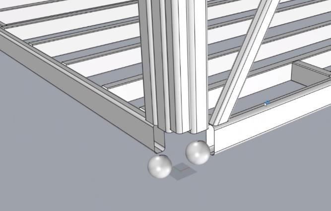
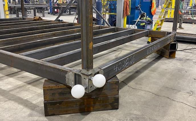
Figure 10. Target placement in the datum showed on the chassis (left) and modelled in its 3D model (right).
Advertisement
The target placements are based on the pre-established 3D representation of its data. For instance, in Figure 10, we can see that this module corner has been set as the datum of the cloud data, andit correlates to the same modelled placement as the software BIM model. This is important since it helps us toensure safe start data that eliminatesthe tolerancesof the rest of the scanning data.
The rest of the targets are also placed in a predetermined location along the module contour. Additionally, extra targets are placed nearby the module at a higher altitude. These targets will provide more reference data regarding the upper part of the module and its roof assembly since the LiDAR scanner somewhat limited in collecting data from the module top due to the tripod placement. Ideally, mitigating all these data variations in the point data cloud is done by automation and discarding out-of-range points based on the set tolerance. The scanner is run by the four module's corners and eachone needs to coverat least 3 targets in its scanning area, that way the quality data keeps consistent. This placement set up is shown in Figure 11.


