penelope
by Aaton
Aaton 35mm 2-Perf & 3-Perf motion picture camera
User’s guide v1.31 (rev.4)
Jan. 07 2010

by Aaton
Aaton 35mm 2-Perf & 3-Perf motion picture camera
User’s guide v1.31 (rev.4)
Jan. 07 2010
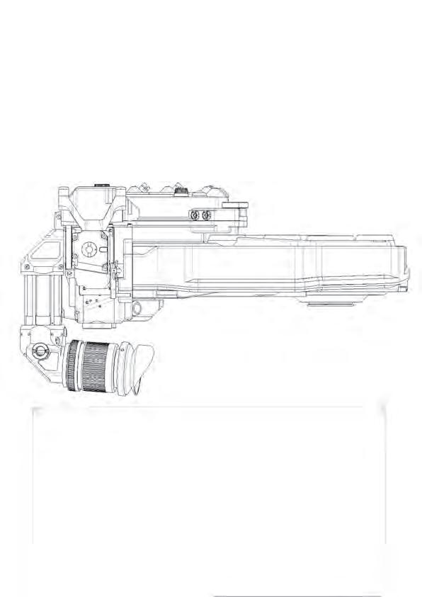
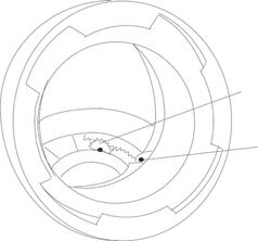
Short eyepiece
Horizon setting knob
Friction adjusting ring
Fischer-2 connector
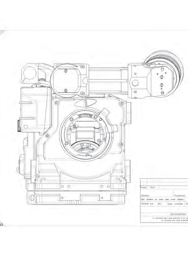
PL mount locking ring
LEMO-2 connector
Rosette
Video (VHR) ND knob
Video housing
Top rod holder
(Extension eyepiece to be ordered separately)
To adjust the image horizon
To adjust the tension of the eyepiece swivel
Eyepiece heating cable connector
Lock ring for 35mm PL mounted lenses
Run/Stop connector
For accessories compatible with ARRI rosettes
To adjust the video light level
Protects the CCD unit
To install a rod (15, 15.8 or 19mm)
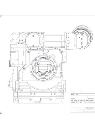
LEMO-6 socket (x2)
USB socket
LEMO-8 socket
Magazine release lever
LEMO-5 socket
Gate
Run/Stop switch
Magazine locking lever
Fastens the upper onboard battery
Provides +Batt, Start and Ground for accessories
Connects to a USB key
Provides 12V, Start, Sync pulse and ground for accessories
Used to release the magazine from the camera body
Timecode communication
Removable gate, 2-Perf or 3-Perf
Runs/stops the film
Secures the magazine to the camera
Upper battery locking screw
Run/Standby switch
Fischer-4 socket
Jog wheel
Pitch control
Video (VHR) ND knob
BNC connectors (x2)
Magazine release lever
LEMO-8 socket
Lower battery locking screw
LEMO-6 socket (x2)
Fastens the upper onboard battery
Runs and stops the film shooting
Provides power and composite video signal for MiniMonitors
Modifies camera parameter settings
Adjusts the claw pulldown stroke
Adjusts the video light level
Provide video output
Unlocks the magazine from the camera body
Provides +Batt., Start, Sync and Ground for accessories
Fastens the lower onboard battery
Provides +Batt., Start and Ground for accessories
Setting keys
Ethernet RJ45 connector
BNC sockets
LEMO-8 socket
Lower battery locking screw
Ethernet cable locking lever
LEMO-6 socket (x2)
Run/Stop switch
Upper battery locking screw
Provides power and composite video signal for MiniMonitors (IVS compatible)
Camera parameters settings
Displays camera and video parameters
Allows access to camera and video operating menu
Computer communication
Video outputs
+Batt., Start, Sync and Ground for accessories
Fastens the lower onboard battery
Locks Ethernet cable
Provides +Batt., Start and Ground for accessories
Runs/stops the
«up» key
«left» key
«down» key
«right» key
«exit» key
«set» key
«vid» key
«sto» key
«tc» key
«on-off» key
«tech» key
«sync» key
«var» key
«iso» key
«mag» key
scroll video assist and film camera setups (direct access to video assist’s gain)
scroll video and camera setups (direct access to shutter phasing)
scroll video and camera setups (direct access to video assist’s gain)
scroll video and camera setups (direct access to shutter phasing)
confirm setup menu
select functions
access video assist setups ((«set» + «vid» activate monitor display)
access Framestore
access Timecode
power film camera electronics («set» + «on-off activate video assist)
access Technical
access synch speed settings («set» + «sync»)
access variable speed settings («set» + «var») and external speed control
access ISO and magazine IDs («set» + «iso»)
access magazine footage settings («set» + «mag»)
Operator’s
Middle
Upper
Locks/unlocks
Manually
Locks/unlocks
Adjusts
Modifies
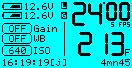
Displays
Modifies
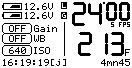
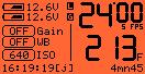
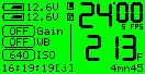
L (mag upper lever) and G (gate) flags
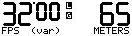
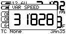
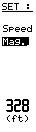
Selected speed
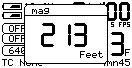
Magazine footage
Remaining time (minutes and seconds)
Time code
Film ISO
Video assist white balance
Video assist gain
Lower battery meter Upper battery meter
Symbols blink - error (magazine upper lock or gate)
Sync/Var./Ext. frame rate (thousanths not displayed)
Remaining or elapsed footage, in feet or meters
Magazine remaining running time
Hour : minute : second [initialization]
ISO for correct Aatoncode matrix exposure
5600°K, 3200°K and Assistant entered values
Current gain setting
Lower battery voltage
Upper battery voltage
Magazine’s upper lock
Collimation cap
Viewfinder friction screw
Tape hook
Socker for accessories
Shutter angle adjustment tool
Pulldown pitch adjustment tool
Secures the magazine to the camera body
Gives access to ground glass collimation adjustment
Adjusts the viewfinder up-down freedom of movement
Holds the gate to subject measurement tape
Power up the camera electronics
To turn ON the camera electronics, press the «on/off» key.
Power up the VHR video assist
To turn ON the video assist, press the «set» key and then the «on/off» key.
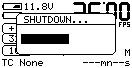
Power down the camera electronics and video assist
Press the «on/off» key, a window appears on the LCD screen. Hold the «on/off» key, a bargraph timer starts counting down. When finished, the screen displays Au revoir.
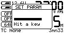
The «set» key
The «set» key gives access to the camera’s settings. While pressing the «set» key, a window appears for a few seconds allowing you to access the desired parameters.
The TEST mode lets you open the shutter and keep it protected inside the camera body. This is used to check the gate for cleanliness and to find the image while doing a steadiness test, this lets you find the correct film/perf position for the second film passage if you are using the double exposure method.
To access the TEST mode, press the «Run/Stop» switch (A) – located on both the Assistant’s and Operator’s sides — and hold it pressed for 3 to 4 seconds. When the shutter opens, the display background color turns dark blue, release the switch. If you want to inch the film frame by frame, press the upper key (C) located Operator’s side. To leave the TEST mode, press the «Run/Stop» switch again for 3 to 4 seconds.
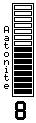
The viewing screen carries illuminated markings referred to as Aatonite. The brigtness level is user adjustable using the middle (B) or upper (C) keys located on the Operator’s side. The configuration of these markings is different from one screen to another, see the screen illustrations, Chapter 5.
NOTE: the brigtness level can also be adjusted while the film is running. A4
Film camera status
The LCD screen color informs the camera crew about the shooting status from a distance.
Light cyan
The camera is in STANDBY.
Orange
The camera is in RUN, but has not yet reached the selected speed.
Green
The camera is in RUN at the selected speed.
Purple
The camera is at end of film
A problem has been detected, e.g. film jam.
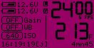
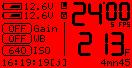
When a problem has been detected, the LCD screen’s background turns red followed by an explanatory message.
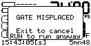
The camera gate is easily removable to allow switching between 2-Perf and 3-Perf formats. The correct positioning of the gate is mandatory for proper camera functioning and focused pictures. The camera gate holder is equipped with 4 sensors to check the gate position, if the gate is not properly positioned, the camera displays the message GATE MISPLACED and refuses to run. Remove the gate and reinstall it.
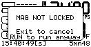
The magazine top locking lever, located on top of the camera body, insures the magazine’s proper positioning. It is equipped with a position sensor which does not allow the camera to run if this lever is unlocked, the message MAG NOT LOCKED is displayed and the camera refuses to run. Lock the lever and press RUN.
An embeded RFID chip identifies each magazine. It enables associating a letter (A - J) with each magazine, allowing the film speed and remaining footage to follow each magazine.
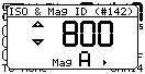
Press the «set» key and the «iso» key to enter the ISO menu, then press the «left» or «right» key to select the desired letter.
Press the «set» key, then the «mag» key to access the MAG menu. If a full 400ft roll has been loaded, press the «mag» key two times to adjust the footage to 400ft (122m). If you load a short end in the magazine, check the length with the magazine footage counter and enter the same value into the MAG menu by pressing the «up» or «down» key. This value is stored for each RFID magazine, identified by a letter from A to J.
While in the Mag menu, press the «left» or «right» key to select the desired measuring unit.
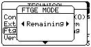
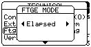
Penelope can display either the remaining or the elapsed footage. To select the mode, press the «set» key then the «tech» key to open the Technical Menu.
Press the «down» key to select the Ftg Mode item and press the «right» key to access it. Choose between Remaining or Elapsed by pressing the «left» or «right» key. Press the «set» to validate your selection, then «exit».
Measure the remaining footage by rotating the mechanical footage indicator (located on the door) counterclockwise.
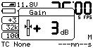
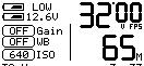
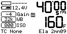
Video gain
The video assist gain is directly accessible through the control panel.
Press the «up» or «down» key to change the video gain.
Wait for 3 seconds or press the «set» key to validate. The adjustment range is -10dB to +12dB, in 1dB steps.
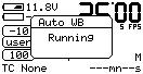
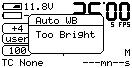
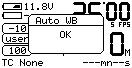
Press the «set» key, then the «right» key to activate the Auto White Balance.
If there’s too much light (or not enough), the message Too Bright or Too Dark is displayed. When the white balance is correct, OK is displayed.
NOTE: The video assist switches automatically to the User’s Color Temperature mode. The stored RGB values can be modified in the Video Menu, see Chapter 4.

The PL lens port
The PL lens port is the standard mounting system delivered with Penelope and allows the use of all 35mm ARRI PL mounted lenses.
The PV lens port
The PV lens port is the standard mounting system for the Panavision cameras, it can be installed on Penelope.
Installing the lens
To install the lens on the camera body, turn the outer locking ring counterclockwise until it stops. If the port cap is on, remove it. Align the four protruding flanges on the lens with the four corresponding cutaways in the locking ring and insert the lens into the camera port so that its flanges rest evenly against the lens seat. Tighten the locking ring by turning it clockwise until the lens is secured and the locking ring is set firmly. Make sure the locking ring is tight enough so that it cannot be inadvertantly unlocked.
i/lenses compatibility
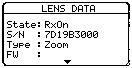
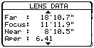
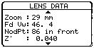
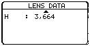
In order to display the data coming from a Cooke/i lens on both the camera display and the video monitor, press the «set» key then the «tech» key to open the Technical menu. Select the Lens Data item and press the «right» key to access it. With the «right» key, select Rx ON or Rx OFF. Press «set» to validate the selection. If ON is selected, the data will be displayed.
Flange focal distance.
Refers to the critical distance from the lens seat to the film plane. With the PL port, the precise FFD of Penelope is 52mm -30 to -40 microns as measured with a depth gauge in the lens port. With the PV port, the FFD is 57.15mm -45 to -55 microns
It is recommended that these tolerances be checked and maintained by a qualified technician. The combination of FFD and back focus distance of a lens directly affect the precise focus (and resulting image sharpness). Make sure these critical measurements are strictly upheld. When using an unfamiliar lens for the first time, check that the eye focus matches the tape-measured focus marks on the lens, and/or shoot a focus test.
Eyepiece
Penelope viewfinder is designed to be fully orientable, providing left or right side viewing and upright image in any position. The viewfinder arm is equipped with an eyepiece that can be used for handheld and tripod operation.
The eyepiece can be equipped with a heating system which receives its power from a cable connected to the Fisher-2 socket, located on the camera front body, above the lens mount.
For dolly work, an optical extension (280 mm) can be inserted between the viewfinder arm and the eyepiece.
First remove the eyepiece by rotating the locking ring (A) clockwise until it reaches its stop and gently pull the eyepiece. To install the finder extension, align its four protruding flanges with the four corresponding cutaways in the viewfinder locking ring and insert it into the viewfinder port so that its flanges rest evenly against the lens seat. Tighten the locking ring by turning it counterclockwise until the extension finder is secured in place and the locking ring is firmly set. Install the eyepiece on the finder extension. A
The screw (B) at the base of the viewfinder, allows you to modify the viewfinder left/right lateral friction. Turn counterclockwise to increase the friction. Turning this screw until it reaches its stop, locks the viewfinder’s left/right movement.
The friction adjusting knurled screw (C), located on the front of the viewfinder, can be used to adjust the tension of the eyepiece swivel, depending on the Operator’s preference and on the type of viewfinder being used. When using the standard eyepiece, tension should be relatively light to allow for movement with a moderate amount of pressure. When using a finder extension, tension should be increased to support the additional weight.
To adjust the tension of the swivel, rotate the knurled screw (C), clockwise to increase tension and counterclockwise to decrease tension.
If the rotation of the image seen through the camera’s viewfinder does not exactly match what is seen with the naked eye, there is a fine adjustment that can be made to the image’s relative horizon. Find the knurled knob (D) located on top of the viewfinder. While looking through the viewfinder, turn the knob in order to adjust the image’s upright position.
NOTE: the knob needs to be turned 180° when installing an eyepiece extension.
Before shooting, the diopter setting of the viewfinder should be adjusted to the Operator’s eye. To set the diopter, use the diopter set ring (E ) located on the short eyepiece.
Look through the viewfinder while rotating the diopter set ring until the edge of the viewing screen cross-hair is in sharp focus. It is recommended to performe this adjustment with the port cover off and no lens on the camera.
Note that the diopter set ring is engraved with numbers and dots. Use them to quickly recall your particular setting when more than one person is looking through the viewfinder.
To prevent light leaks through the viewfinder, the eyepiece shutter must be closed any time the camera is running film and the Operator’s eye is away from the eyepiece.
To close or open the eyepiece shutter, use the small silver lever located on the eyecup ring (F ).
The viewing screen (ground-glass) is interchangeable. Viewing screens for 2-Perf and 3-Perf formats can be selected in «Viewing Screens List», Chapter 5.
The viewing screen can easily be removed by the user. First remove the port cap. Remove the battery (s) and clear the mirror shutter so that it is positioned safely inside the body by rotating it close to its center shaft with your finger. Look into the port and look at the screen directly above the aperture gate (G). Get a piece of Post-it, that will take-out the viewing screen without dirtying it. Put the Post-it on your forefinger, the sticky part of it facing up. Smoothly put a finger on the viewing screen, and remove it.
To reinstall the screen, look into the port and locate the right and left lip of the viewing screen holder. Gently push the screen straight into the holder, aligning the two white marks of both holder and screen. Proceed as before, with a piece of Post-it on your finger.
The image focus on the viewing screen (ground-glass) should match the lens barrel focus mark and the focus on the film. Before adjusting the viewing screen, be certain that the flange focal distance of the camera is set according to the manufacturer specifications.
To proceed, you must unscrew and remove the cap (H) located on the Operator upper side of the camera body. The open hole gives access to the screen holder that you can up and down move by turning its Allen screw (2mm Allen key).
Set a focusing chart at a known distance. Adjust the focus mark of the lens to the same distance. Get a sharp image on the ground-glass by moving the holder up or down with the Allen key. Double check the focus of the viewing screen using the focus ring of the lens. If the image is still not sharp, perform this operation again.
The reflex mirror shutter diverts the lens rays to the viewing screen while the claw pulls the film down to the next unexposed film frame. It is made of a 180° glass mirror, and a 180° black metallic shutter hiden underneath the mirror. The metallic shutter can be slid (un-hidden) to four-positions which make for 180°, 178°, 150°, 144° shutter opening angles.
To adjust the shutter opening angle, unscrew the tool marked Sh located in the rear of the carrying handle. Make sure the battery has been removed from the camera, remove the lens port cap.
Locate the tool guiding hole to the lower right of the inside lens holder. Gently rotate the shutter at its base with your finger until the brass driving gear is centered underneath the tool guiding hole.
Insert the Sh tool through the guiding hole and into the brass gear. Rotate the tool until the appropriate notched angle setting is reached ; turning counter-clockwise reduces the shutter opening, turning clockwise increases the opening.
A shutter blade carrying the angle values is visible at the left edge of the mirror. Make sure the white line to the immediate right of the 172.8°, 150° and 144° markings meets the left edge of the mirror. When the adjustment is done, remove the tool and store it back in the carrying handle.
Each time you have to put a finger inside the camera body, you must remove the battery. If by mistake the camera starts running while your finger is touching the mirror shutter, the mechanism can be seriously damaged (and your finger too).
• 180° for filming 25fps under 50Hz HMI lighting, and 24fps under 60Hz.
• 172.8° for filming at 24fps under 50Hz HMI lighting.
• 150° for filming at 25fps under 60Hz HMI lighting.
• 144° for filming an NTSC monitor at 24fps while minimizing the roll bar visibility.
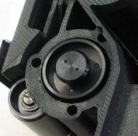
Adjusting the pitch
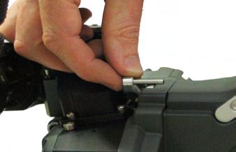
To adjust the pitch, use the Pitch tool located in the camera carrying handle. Remove the pitch protector cap (A) located Assistant’s side near the Pitch label. Insert the tool inside the opening.
You will feel a screw that you will turn counterclockwise until it stops; the pulldown pitch is now at its maximum.
Put a loaded magazine on the camera, and keeping the tool in its position run the camera which will run with a clicking noise, due to the perf being hit by the claw.
Turn the tool clockwise until you hear a purring sound. Once you have reached this setting, turn the tool counterclockwise by about 20º; this will accomodate any variation of the film pitch that occurs between different film stocks or under humid and hot weather conditions.
NOTE: Make this adjustment while using the film stock you will be shooting with.
The film gate also features a side pressure bar (B) at the level of image exposure to insure maximum lateral steadiness.
Penelope requires a minimum 12.4V power source.
An Aaton 14.8V 4.2Ah Lithium-Ion onboard battery can run the camera for twenty 400’ magazines, i.e. three hours of 2-Perf shooting.
When the video-assist is activated and power hungry accessories such as zoom focus and iris remote control, video transmitter and monitor are connected to the LEMO sockets, it is highly recommended to install an additional Lithium-Ion battery.
When running AatonCode, you should never leave the camera unpowered. Thanks to a built-in super-capacitor, the TCXO can handle a 10 minute power interruption, so you have plenty of time to change the batteries. Nevertheless remember that a depleted battery still has enough power to keep the TCXO alive for hours, do not remove it unless you have a fresh battery on hand.
When running the camera from a heavy battery pack on the floor, the cable is disconnected during moves and at lunch time, the super-capacitor buffering is not enough, put a battery onboard (even a depleted one) before disconnecting the power cable. After cable reconnection, confirm that timecode is still incrementing by checking the control panel.
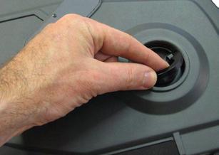
To install a battery, loosen the blue knurled screw (A) approximately four or five turns. Push the battery plug into the XLR-4 socket, then tighten the knurled screw until the battery tab is held firmly.
The Aaton Li-Ion batteries must be charged with the Aaton Cha-Li three-hour charger. If you can’t even tolerate the low noise level of its fan (around 30dBA at one meter), use a silent Aaton Chascot five-hour charger.
Both chargers can simultaneously charge two batteries.
A variety of 14 to 16VDC sources can be used to power the camera: AC-DC power supplies, battery blocks, Lithium-Ion, and lead-acid car batteries.
Since Penelope’s power sockets are universal XLR-4s, you should always carry an XLR-4 powercable in your package.
Regarding AC-DC power supplies, it is recommended that the unit be able to supply 10A peak and 60W. Before connecting any non-standard source, always make sure that the pin configuration of the unit is correct. See Chapter 5 for wiring details.
Three crystal controlled tri-phase motors are in use: one for the claw mechanism, one for the magazine drive, one for the shutter. Penelope is capable of speeds between 3 and 40fps with a standard Li-Ion 14.8V battery.
Penelope provides preset crystal speeds (SYNC) and Operator tuned crystal speeds ( VAR) in .001 increments, all accessible from the LCD control panel. It should be noted that once set, the fame-rate thousandths are not displayed.
Available preset speeds are : 6, 12, 18, 20, 23.98, 24, 25, 29.97, 30, 33.33, 36 and 40fps. The «sync» key allows for quick access to these frequently used speeds.
If any other speed is desired, or if the camera speed must match the frequency of a monitor to eliminate a rolling bar, the «var» key should be employed. The speed selector gives access to any speed between 3 and 40fps in .001 frame steps. A phase adjustment of the variable speed is available while pressing the «left» and «right» keys.
The camera speed can also be adjusted while the camera is running in either sync or variable mode. For more information on these speed functions, refer to the «LCD control panel and jog wheel» section of this chapter.
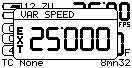
Penelope can be driven externally from devices such as film to video synchronisers and external speed controls. In these situations, the camera «var» selector must be set to EXT mode. If such a device is connected and the selector is not set to EXT, the camera will run at the speed indicated on the display.
Keep in mind that, with certain manufacturer’s speed controls, it may be possible to ask for a speed higher than 40fps. In that case, the camera won’t run at speeds higher than the 40fps factory limit. It will run at 40fps, and the fps value on the LCD control panel will be blinking.
Penelope utilizes a straightforward and intuitive control panel structure in conjunction with a jog to access and adjust all Operator parameters.
Located to the immediate left of the LCD screen, the jog (A) is a small knob designed to speedup many user functions. It allows quick adjustment of parameters such as a precise 5-digit speed or a short end footage entry.
Basics: «sync», «var», «iso», «mag»
The «set» key lets you enter the basic film camera settings, they are modified by either toggling the «up», «down», «left» or «right» key, or by rotating the jog. Press «set» to accept your choice, press «exit» to leave things unmodified.
As a standard feature, Penelope is equipped with the AatonCode in-camera timecode recording. Timecode is exposed onto the film by optical projection of seven micro-diodes located in the gate. These micro-diodes flash rapidly to form the code as the film rolls through the gate between exposures.
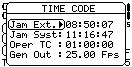
To enter the AatonCode Menu, press the «set» key, then «tc». Choose the way you want to initialize the TC using the «up», «down», «left» or «right» key.
If AatonCode has been initialized in the camera, you can see it in the left bottom corner of the LCD display in the format: hours : minutes : seconds
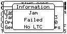
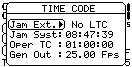
• The «e» flag indicates that the timecode has been jammed from an external TC signal, LTC through the LEMO-5 connector. If no signal is present, the message Jam Failed No LTC is displayed. If a signal is present, the TC is displayed.
• The «a» flag indicates that the timecode has been initialized using the Aaton OriginC+ master clock through ASCII communication.
• The «s» flag indicates that the timecode has been jammed from the internal system time of the camera.
• The «o» flag indicates that the timecode has been manually entered by the operator.
• The «b» flag indicates that the timecode has been memorized during a short power down. The camera is equiped with an instantly charged supercapacitor buffer that is designed to keep time between battery changes. The super-capacitor allows 10 minutes for battery replacement before timecode is lost.
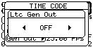
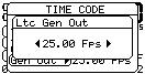
Timecode generator
To activate the camera’s timecode output, press, press the «set» key, then the «tc» key. With the «down» key, go to Gen Out Menu.
With the «left» or «right» key, select from: OFF / 24 Fps / 25 Fps / 29.97 df / 30 Fps. Press the «set» key to accept the change.
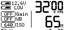
When using AatonCode in Penelope, the ISO setting must be adjusted to the exposure index of the film stock. The ISO selection insures that the matrixes recorded on the edge of the film are correctly exposed. This ISO value is stored for each RFID magazine, identified by a letter from A to J. If AatonCode is not running in the camera, the ISO setting has no effect. Press the «set» key and then the «iso» key to enter the ISO Menu. Use the «left» or «right» key to associate a letter (A - J) with each magazine. Use the «up» or «down» key to adjust the ISO setting. Make your selection between 25 and 1000 ISO, by rotating the jog or by pressing the «up» or «down» key.
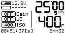
Upon being powered up, the control panel’s Home page displays the camera’s speed selection and whether it is in SYNC, VAR or EXT mode. When the camera is turned on, the actual running speed to the .01 frame is displayed.
To adjust the preset speed, press the «set» key, then the «sync» key. Make your selection of stepped crystal speed between 6 and 40fps by rotating the «jog» wheel, or by pressing the «up» or «down» key. Press the «set» key to validate your selection.
To choose a specific speed, press the «set» key, then the «var» key. Make your selection of any .001 incremented crystal speed between 3.000 and 40.000fps via the «jog» wheel, or .1 with the up or down key. Press the «set» key to validate your selection.
For the film camera to be driven from an external source such as external speed control generating 100ppfp (pulses per film pict), press the «set» key, then the «var» key. Press the «var» key once again to switch from VAR to EXT SPEED.
Press the «set» key to validate your selection.
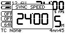
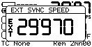
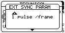
To synchronize the camera to the scanning rate of a computer or video monitor while removing the roll bar, press the «set» key then «tech» to open the Technical Menu.
Select the EXT SYNC item with the «down» key then the «right» key to access it. Select 1 or 2ppvf (pulse per video frame) with the «up» or «down» key. Press the «set» key to validate your choice.
To get access to the external sync speed mode, press the «set» key, then the «var» key. Press the «var» key twice to switch from VAR to EXT SPEED and to EXT SYNC SPEED. If a valid incoming sync signal is detected, the appropriate speed is displayed. Run the camera and press the «up» or «down» key to remove the roll bar. This one-time phase adjustment sets the relationship of the camera shutter to the source signal. After this initial phasing this relationship remains identical every time the camera is turned on, the roll bar remains off-screen.
NOTE: If the source signal is faulty or invalid, the camera runs at 3fps, the speed icon is blinking.
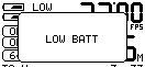
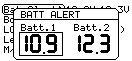
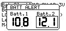
If Batt.1 or Batt.2 reaches the minimum preset level, e.g. Batt Alert = 14.4V, an alert appears on both LCD screens and a red LED blinks in the camera viewfinder.
The camera continues to run properly and LOW BATT is displayed in front of the battery icon.
If both batteries are low, the alert is displayed on both the Assistant’s and Operator’s screens.
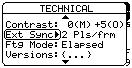
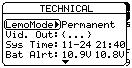
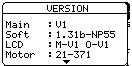
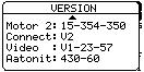
The Technical Menu lets you access to: LEMO mode, Video out, Syst Time, Batt Alert, LCD Param, Ext Sync, Ftg Mode, Version, Lens Data, Video Capture, Load Soft, SlowStart.
To access the Technical Menu press the «set» key then «tech».
Select one of the sub-menus and press the «right» key.
Select the mode by rotating the «jog» wheel, or pressing the «up» or «down» key.

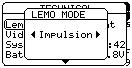
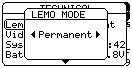
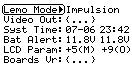
Two Run/Stop modes are available for accessories using Penelope’s LEMO connectors.
• IMPULSION for accessories using a pulse signal.
• PERMANENT for the Aaton wooden handgrip, and ON/OFF switches and cable made for the 35-III, Xtera, XTR-prod cameras.
Select the LEMO Mode item and press the «right» key. Select the mode by rotating the «jog» wheel, or by pressing the «up» or «down» key. Press «set» to validate your selection.
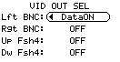
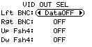
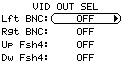
Penelope offers four independently programmable video outputs: two BNCs and two FISHER-4s). Each can be turned OFF to save power (OFF ) or turned ON with picture only (DataOFF ) or with picture and burned-in characters (DataON).
Select the Video Out item and press the «right» key. Select the desired video output by using the «up» or «down» key, press the «left» or «right» key to switch between: OFF, DataOFF, DataON. Press the «set» key to validate your selection.
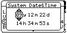
To manually set the internal camera timecode, press the «set» key then the «tech» key to open the technical menu. Select the Sys Time item and press the «right» key to access. The display will show the camera date and time.
Use the «left» or «right» key to select the following parameters: year, month, day, hour, minute, seconds. And use the «up» or «down» key to modify each one of them.
Press the «set» key to validate your selection.
Penelope displays alerts when the battery voltage falls below a preset level. The thresholds set for Batt.1 and Batt.2 do not overide the cameras default minimum levels.
Select the Bat Alert item and press the «right» key to access it. Select a value between 14V and 15V for each battery by rotating the «jog» wheel, or pressing the «up» or «down» key. Press «set» to validate your selection.
The alert level of Aaton Lithium-Ion onboard batteries must be set at 14.4 minimum, this will leave enough power for you to shoot a complete 400 foot magazine.
NOTE: firmware v1.28 and up is required to adjust the warning level to 14.4V.
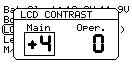
To adjust the LCD contrast, select the Contrast item and press the «right» key to access it. Select Main LCD Contrast by rotating the «jog» wheel, or by pressing the «up» or «down» key. Press the «right» key to access the Operator’s LCD and follow the same procedure. Press the «set» key to validate your selection.
To remove the roll bar while filming a video monitor, the film camera must be synced to its vertical scanning rate, depending on the sensor used to measu- epending re this rate you must set the Ext Sync item to either 1 or 2 ppvf, see p.37.
You can display either the remaining or elapsed footage in the magazine. Use the «down» key to select the Ftg Mode item and press the «right» key to access it. Choose between Remaining or Elapsed by pressing the «left» or «right» key. Press «set» to validate your selection, then the «exit» key.
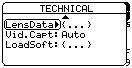
For troubleshooting, access to internal camera technical information might be useful before contacting your service center. Select the Version item and press the «right» key to display it (read only).
To display on both the camera sceen and the video assist monitor the data coming from a Cooke/i lens installed on the camera port, select the Lens Data item and press the «right» key to access it. With the «right» key, select Rx ON or Rx OFF. Press «set» to validate your selection.
Still images (jpeg format) can be captured from the video assist camera and copied onto a FAT32 formatted USB key. When the USB key is recognized, a disk icon appears on the screen. See p.61.
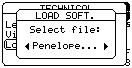
To update the firmware, copy the new Penelope_Vx.xx.flb file onto a USB key (FAT32 formatted), and plug the key into the USB socket. Power-up the camera electronics with the «on/off» key. When the USB key is recognized, a disk icon appears on the main screen.
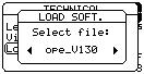
Select the LoadSoft item and press the «right» key to access it. Select the version by pressing the «left» or «right» key, and wait for 2 seconds to see the complete version names scrolling. Press «set» to validate.
The messages Loading, Prog Start, Erasing, Programming, and Success will successively appear, and then the final one: Please Shutdown. Shut the camera down by pressing the «on/off» key for four seconds, then power-up again, the new software is installed.
NOTE1: it is STRONGLY RECOMMENDED to install freshly charged batteries before starting the install process. If the camera looses power before it has completed loading the new software, the unit will have to be returned for repair.
NOTE2: do NOT power down the camera until you are told to.
NOTE3: following a firmware installation, at camera start up a message might appear indicating an automatic update of both the motor and logic boards.
Three keys, close to the vertical LCD screen, are located on the Operator’s side: «lower» (1), «middle» (2), «upper» (3).
• Press the «middle» or «upper» key to adjust the AatoNite frame brightness, see Chapter 1.
• Press the «lower» and «middle» keys to select the SPEED item, press the «lower» key to make it blink, you can now modify the SYNC and VAR film running speed. Press the «middle» or «upper» key to modify the speed value. Press the «lower» key to validate.
• Press the «lower» key and «upper» keys to select the MAG item, press the «lower» key to make it blink, you can now set the magazine footage. Press the «middle» or «upper» key to modify the footage value. Press the «lower» key to validate.
From Rune Ericson, based on his experience in filming in Greenland.
• When filming outdoors in extreme cold, the camera and lenses should not be taken indoors at all, so as to avoid condensation on the electronic parts and glass surfaces. In any case, the camera (and lenses) should not be stored above 0°C. If the camera must be taken inside, then it should be put in a hermetically sealed container. It should be allowed to thaw for a few hours before being removed from the sealed container.
• The raw stock should also be kept below zero. For the same reason as above, the magazine should be loaded in the cold.
• The Aaton Li-Ion onboard batteries should be used in preference to battery belts, several small batteries can be warmed up much more easily than one large heavy one. Each member of the shooting crew can keep one in his or her breast pocket.
• At 30°C below zero, Rune advises documentary filmmakers to sleep with the batteries in their sleeping bag...
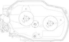
The Penelope magazine is designed to be quickly installed or removed, and to be loaded easily, it handles up to 400ft (122m) loads of 35mm film stock. The magazine sprockets are driven through a magnetic clutch by a motor located in the camera body itself. This system reduces noise and power consumption, and prevents mechanical abuse in case of misloading. The feed roll footage can be checked through a mechanical footage counter located on the magazine door. The remaining or elapsed footage also appears on the camera control panels, see Chapter 1.
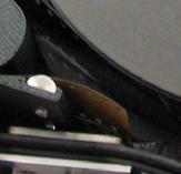
Claw rear pressure plate
This plate (A) is located at the front of the magazine. When the loaded magazine is installed on the camera body, its main function is to hold the film as the claw engages the film perforations. Proper positioning of this element is essential to steadiness and quietness of operation.
The striped pressure plate (B), positioned at the camera’s picture taking gate level, holds the film in the right back focus position.
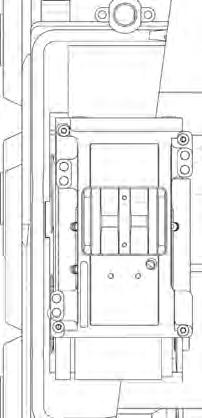
A
3.3 Loading the film in 17 steps
The magazine design allows for a quick and easy loading procedure and reduces the number of operations to be performed in the changing bag, to the absolute minimum.
the light
1 Place the magazine in front of you, throat on the left.
2 Turn the mechanical footage counter (A) clockwise until it locks in place.
3 Unfasten the three blue locking levers (B), turning them counterclockwise.
4 Open the door.
5 Check the magazine for dust and debris.
6 Put the magazine in a dark room or changing bag.
7 Remove the film from its can and bag. Place the film on the feed spindle with its winds clockwise.
DON’T FORGET to press the center of the core lock mechanism to lock the core in place (A).
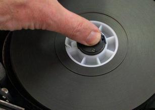
8 Push the film head into the center slot (B), until it engages the inner sprocket wheel.
Still in the dark
9 Guide the film with your left forefinger and turn the take-up core holder clockwise, making sure the film perforations engage the sprocket teeth.
10 When the film comes out of the sprocket assembly, gently pull on it.
11 Pull approximately 20 cm (8 inches) of film and insert it in the bottom slot until it meets the lower sprocket teeth.
Still in the dark
12 Guide the film with your left thumb (A) and forefinger and turn the takeup core holder clockwise until the film exits on the other side of the sprocket assembly (B). Continue to turn the take-up core holder until the film reaches the bottom roller (C).
13 Place a core on the take-up side spindle, press the center of the core holder to lock the core in place. Fit the film end into the plastic take-up core and wind on a few turns clockwise with the emulsion in.
14 Close the door. The remaining steps are performed in the light.
In the light again
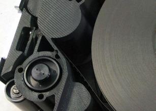
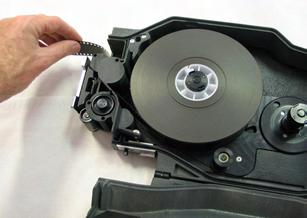
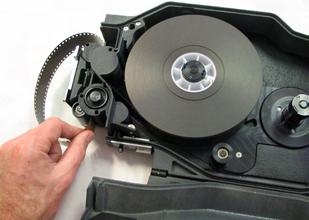
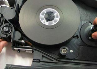
15 Engage the take-up clutch knob by pulling its lever up.
16 Push the loop adjusting sprocket release button and hold it pressed. Turn the take-up clutch knob clockwise (while gently pressing on it) to shorten the loop size until the loop adjustment tool is held between the film and the pressure plate.

NOTE: the loop adjustment tool makes a loop corresponding to approximately 37 visible perforations.
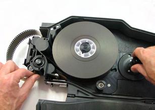
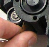
17 Once the loop has been set, check that the lower sprocket release button has returned to its up position.
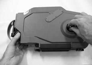
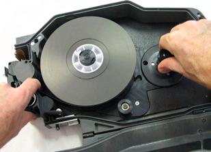
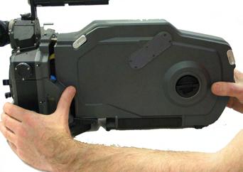
To install the magazine, stay at the rear of the camera body, Operator’s side. Place your right hand underneath the magazine while your left hand is firmly holding it at the midway point of its rear. Rest the nose of the magazine on the camera base, hold the camera body with your left hand while pushing the mag in the bottom dovetail and into the aperture area with your right hand. Make sure that the top of the nose of the mag is parallel to the camera as you guide the mag in place. Push firmly and evenly until you feel and hear that the mag snaps against the aperture area.
Don’t forget to lock the magazine by pushing the magazine upper locking lever.
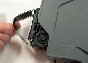
To remove the magazine, stay at the rear of the camera body, Operator’s side. Unlock the magazine upper lock lever and push the magazine release lever (A) toward the front of the camera.
Pull the mag off the camera body.
To power up the VHR video assist, press the «set» key then the «on/off» key once the film camera electronics have been powered up.
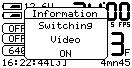
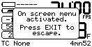
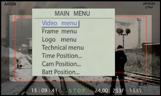
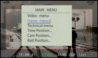
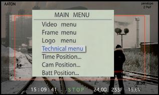
To display the VHR Menu (Main menu) on the video monitor screen, press the «set» key then the «vid» key. A message is displayed on the Assistant’s control screen (see pict. top right).
The VHR Menu contains five items
4.1 Image look (Video menu)
4.2 Frame & mask (Frame menu)
4.3 Proxy capture (Vid. capture)
4.4 Metadata insert (Technical menu)
4.5 Logo insert (not yet activated) the «up» and «down» keys select an item. the «set» key opens an item. the «up», «down», «right», «left» keys modify the parameters. the «exit» key enters the change.
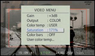
4.1 Image look (Video menu)
Opens access to:
• Gain
• Color temp.
• Color saturation
• Color Bars
• Color/ B&W out
• Gain
Use the «up» or «down» key to modify its value. It can also be modified by using the direct access shortcut (see p. ).
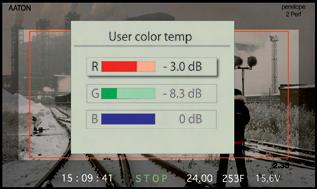
• Color temp.
- Tungsten or Daylight. Selecting one or the other makes [3200K] or [5600K] appear in the CT field of the Assitant’s control screen.
- Manual white This is directly activated by pressing the «set» then the «right» key. To perform a manual white balance, put a piece of white paper in front of the taking lens. If there’s too much light (or not enough), the message Too bright or Too dark is displayed on the Assitant’s control screen. White balance done, OK is displayed. [M-WB] appears in the CT field.
- Manual RGB (USER) currently opens access to the ‘User color temp’ line. Press the «set» key to display three RGB bargraphs, press the «up» or «down» key to select one of them and press the «left» or «right» key to modify the dB values. This lets you cope with 1800K to 7000K lighting conditions. Press the «exit» key to validate. [M-RGB] appears in the CT field of the Assitant’s control screen.
• Color saturation
A highly saturated image displays vivid colors, less saturated it appears as greyish. Saturation goes up to 200% (factory: 160%).
• Color bars
These bars are useful to calibrate an NTSC monitor by tuning the color phase setting while displaying the monitor’s blue only channel.
• Color/B&W out (Output).
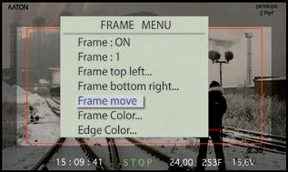
4.2 Frame & mask
Opens access to
• Activation
• Templates
• Top left corner
• Bottom right corner
• Frame color
• Frame move
• Mask appearance
• Activation
Select ON to open access to four ‘frame & mask’ templates and to activate their insertion.
• Templates
Four different templates store the rectangular frame and associated mask to be inserted in the video assist image.
Press the «right» key to select one of the four templates.
• Top left corner
The rectangular frame can be set in size and position to perfectly match the camera viewing screen markings. Press the «set» key to enter and modify the corner position using the «up» «down» «left» or «right» key,
• Bottom right corner
Proceed in the same way as above.
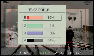
• Frame color
Change the color of the rectangular frame. Play with the RGB values then press «exit».
• Frame move
Lets you move the whole frame in the picture without affecting its size nor ratio.
NOTE: a frame can be set to match the viewing screen markings but it can also be used to outline an object in the picture during a product shot.
• Mask appearence
A transparent mask can be added outside the rectangular frame. You can change its color and its transparency percentage.
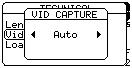
Still images (jpeg format) can be captured from the video assist and copied on a FAT32 formatted USB key. When the USB key is recognized, a disc icon appears on the main screen.
Select the Proxy Capture (Vid. Capture) item and press the «right» key to access it. Select the mode by pressing the «left» or «right» key: OFF, Evry 1s (every second), Evry Ns (every N seconds), AUTO (three seconds after RUN, middle of the take, three seconds before STOP). Press «set» to validate the selection.
4.4 Metadata insert
Metadata insertion can be moved anywhere in the picture with the «up» «down» «left» and «right» keys.
• AatonCode
• Battery voltage
• VITC line & parity
• Lens Data
• Film status
• Software/hardware
• AatonCode
Time, Date, Camera ID. The positionning of these three ‘words’ currently is directly accessible from the VHR Menu (Main Menu).
• Battery voltage
The higher of the two batteries voltage is displayed. When the low battery alert level has been reached, the battery voltage characters start blinking.
• VITC line & parity
PAL VITC lines can be inserted from 10 to 23 (line 19 is common practice).
For NTSC, 13 to 19.
Ask your editing staff the line # they prefer to work with. ODD or EVEN parity interleave: ODD is common practice.
• Lens Data
As transmitted from the Cooke i/lens system.
TECHNICAL
• Film status
Film speed (in fps), and remaining or elapsed magazine footage (in foot or meter).
The shooting status appears as RUN in green characters, or as STOP in red. Its positionning is factory set and can’t be moved away from the center bottom of the video assist monitor.
• Software/hardware
The video assist software version and the hardware model is displayed on the Assitant’s control screen as well as on the video monitor screen.
Logos can be inserted anywhere in the video picture. This function is not yet installed.
• To upload a Logo, connect your computer through the ‘LEMO-5 Serial Port’ cable.
• Once the Logo has been imported, you can modify its transparency and its position.
LEMO-2 On/Off
Heating cable
Type Functions Diagram Pin descriptions (from user’s side) LEMO-8 Speed Controllers 1 Ground
2 One pulse per frame
3 ASCII In/Out
4 + Batt.
5 Tach. out
6 Start
7 Tach. in
8 Ground
Power In
Ground
Start * 3 + Batt. 4 + Batt.
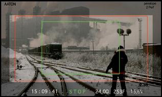
2.39 (with
• The Aatonite frame is in red • 1.78 = 16/9 ratio.