CREED BROOM
Architectural Studio IV-B | ARC 4546 Spring 2024
P O R TF O LI O
CONTENTS
00. project introduction
01. conceptual & programmatic framework
02. schematic design
03. building tectonics/code analysis
04. resiliency measures
05. physical models
00 01 02
project introduction
creed broom | academic portfolio | spring 2024
“bridging into the suspension of disbelief”
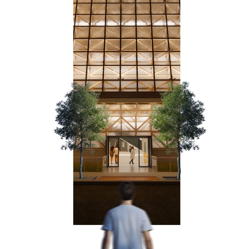
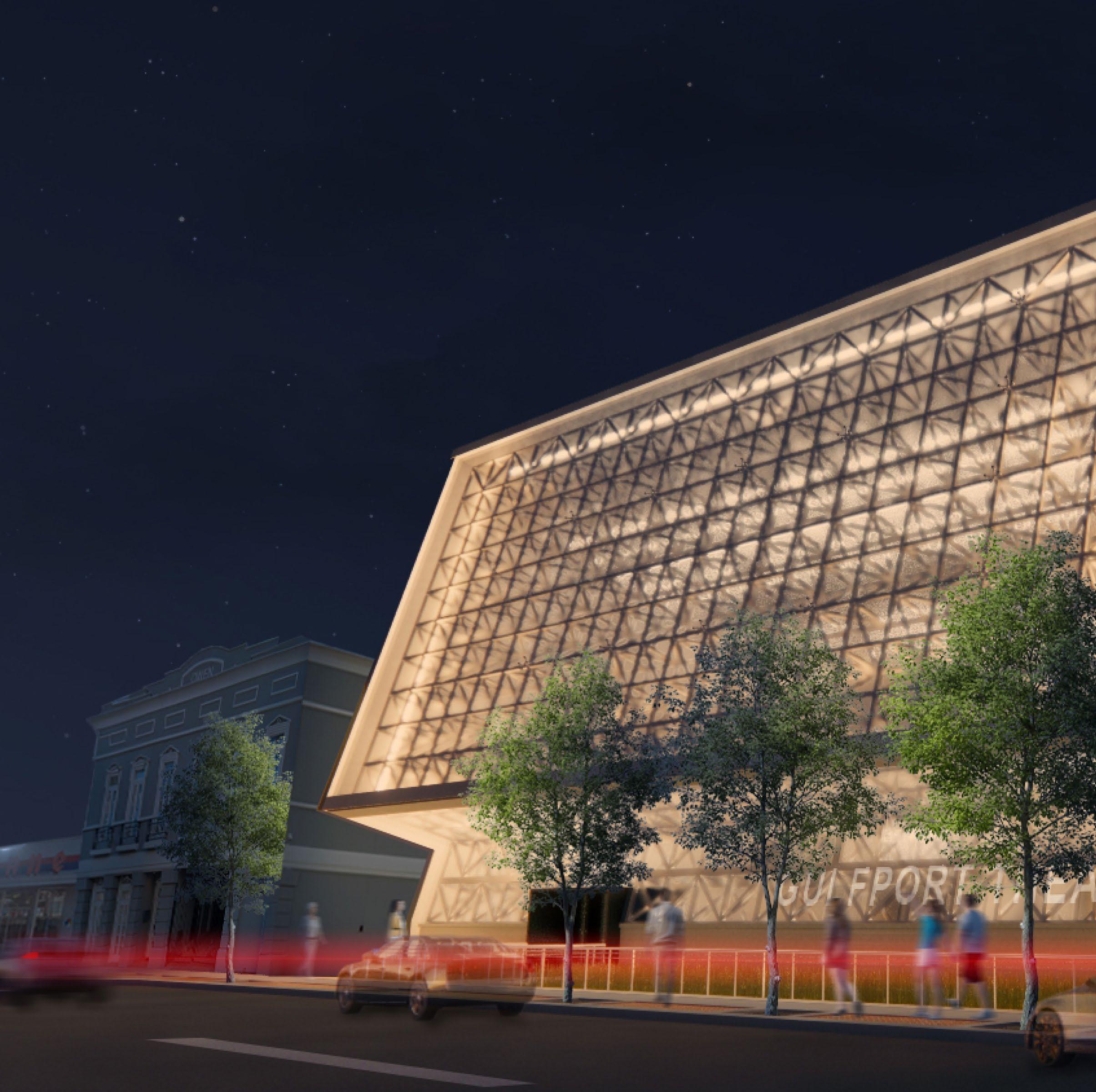
Based in Gulfport, MS, this project focuses on the program of a black box theater. Along with this program of a black box theater, this project takes on the task of designing for a structural steel competition while also challenging itself with the issues of coastal resiliency. For this particular project, this idea of bridging into this alternate reality became an important focus to the program. Achieving this motive became possible through the use of thresholds that extruded through this elegant space frame structure. This portfolio not only outlines the start to finish process of this project, but also a comprehensive application of our education thus far.
01 02 03 00
conceptual framework
creed broom | academic portfolio | spring 2024
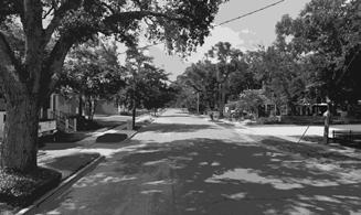
GULFPORT MAPPING PROJECT
IMAGEABILITY & LEGIBILITY
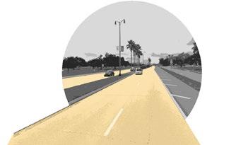
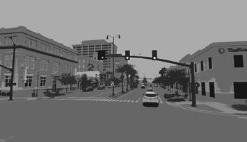
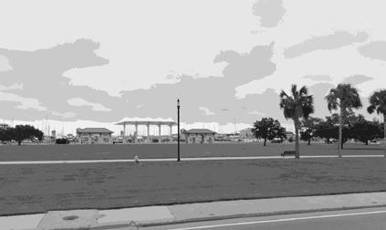
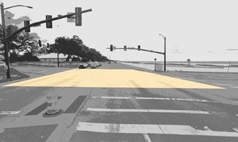
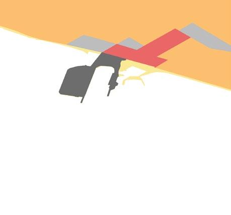
In his book titled The Image of the City, Kevin Lynch beings to organize a framework where he explores the relationship between how a city is perceived versus the basis of its design. In doing this, Lynch chooses to do an analysis on Boston, Jersey City, and Los Angelas, because of the uniqueness of each, by interviewing residents and documenting his own observations. Through this analysis, Lynch is able to depict the integrity an urban design has, as well as how it affects the perception of how users view and interact within the city. For this assignment, we are borrowing this framework of urban analysis that Kevin Lynch has provided and focusing on the aspects of Gulfport, MS. This analysis will unpack the way in which residents and travelers interact and perceive the city and will provide a broad understanding on the imageability and legibility of the city. This analysis will define the imageability by its distinct characteristics that make Gulfport identifiable, while also analyzing the legibility of how the urban footprint has been established and
“Landmarks are another type of point-reference, but in this case the observer doesn’t not enter within them, they are external. They are usually a rather simply defined physical object: building, sign, store, or mountain. Their use involves the singling out of one elements from a host of possibilities. Some landmarks are distant ones, typically seen from many angles and distances, over the tops of smaller elements, and used as radial references. They may be within the city or at such a distance that for all practical purposes they symbolize a constant direction. Such are isolated towers, golden domes, great hills. Even a mobile point, like the sun, whose motion is sufficiently slow and regular, may be employed. Other landmarks are primarily local, being visible only in restricted localities and from certain approaches. These are the innumerable signs, store fronts, trees, doorknobs, and other urban detail, which fill in the image of most observers. They are frequently used cluses of identity and even of structure, and seem to be increasingly relied upon as a journey becomes more and more familiar.” -Kevin Lynch
PATHS
“Paths are the channels along which the observer customarily, occasionally, or potentially moves. They may be streets, walkways, transit lines, canals, railroads. For many people, these are the predominant elements in their image. People observe the city while moving through it, and along these paths the other environmental elements are arranged and related.”
-Kevin Lynch
“Districts are the medium-to-large sections of the city, conceived of as having two-dimensional extent, which the observer mentally enters “inside of,” and which are recognizable as having some common, identifying character. Always identifiable from the inside, they are also used for exterior reference if visible from the outside. Most people structure their city o some extent this way, with individual differences as to whether paths or districts are the dominant elements. It seems to depend not only upon the individual but also upon the given city.” -Kevin Lynch
“Edges are the linear elements not used or considered as paths by the observer. They are the boundaries between two phases, linear breaks in continuity: shores, railroad cuts, edges of development, walls. They are lateral references rather than coordinate axes. Such edges may be barriers, more of less penetrable, which close one region off from another; or they may be seams, lines along which two regions are related and joined together. These edge elements, although probably not as dominant as paths, are for many people important organizing features, particularly in the role of holding together generalized areas, as in the outline of a city by water or wall.” -Kevin Lynch
“Nodes are points, the strategic spots in a city into which an observer can enter, and which are the intensive foci to and from which he is traveling. They may be primarily junctions, places of break in transportation, a crossing or convergence of paths, moments of shift from one structure to another. Or the nodes may be simply concentrations of some use or physical character, as a street corner hangout or an enclosed square. Some of these concentration nodes are the focus and epitome of a district, over which their influence radiates and of which they stand as a symbol. They may be called cores. Many nodes, of course, partake of the nature of both junctions and concentrations. The concept of node is related to the concept of path, since junctions are typically the convergence of paths, events on the journey. It is similarly related to the concept of district, since cores are typically the intensive foci of districts, their polarizing center. In any event, some nodal points are to be found in almost every image, and in certain cases they may be the dominant feature.” -Kevin Lynch
LANDMARKS 01 NODES 02 DISTRICTS 03 EDGES 04 05
CREED BROOM ARC 4733
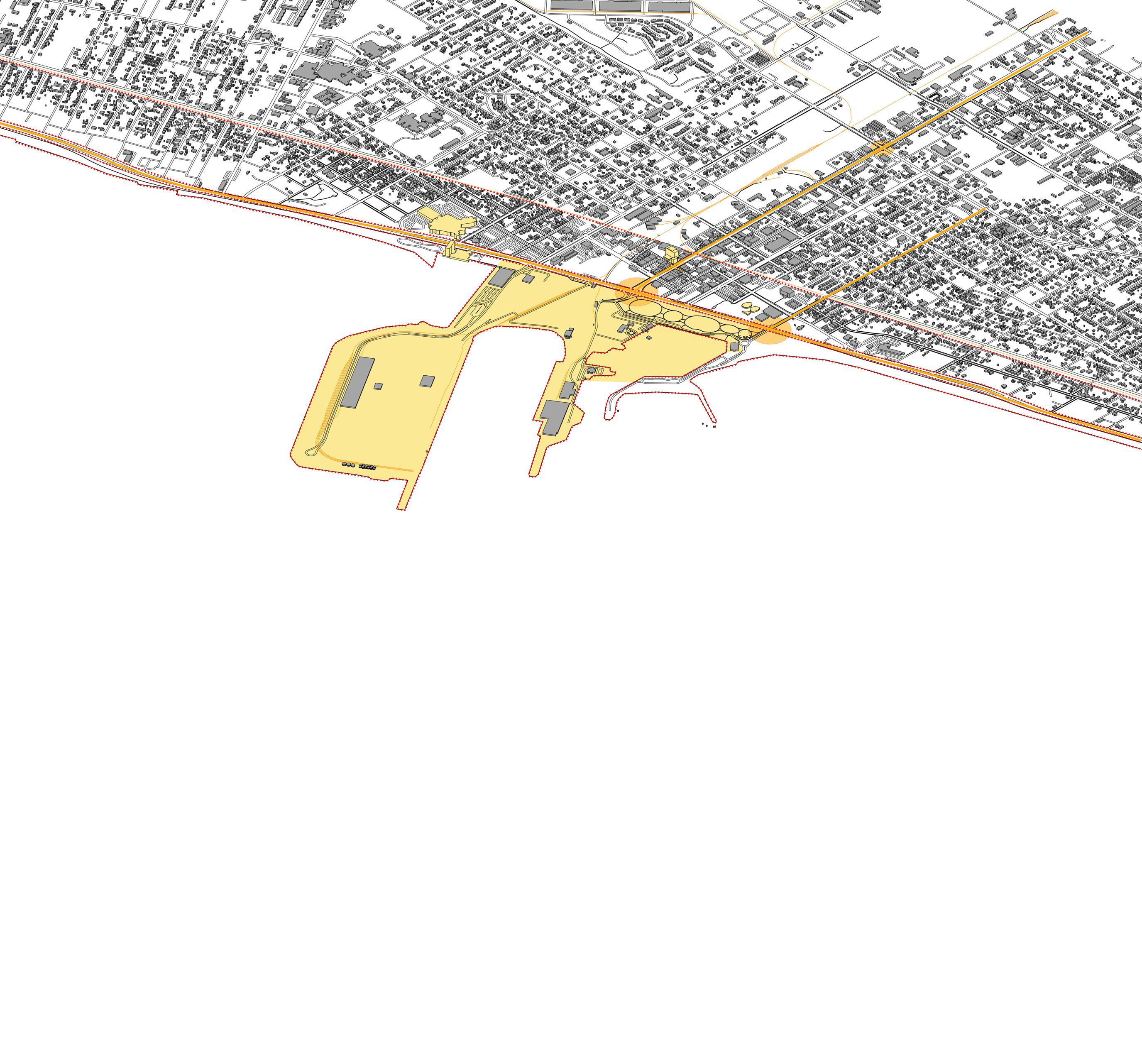
25th + 14th 25th + US-90 20th + US-90 BEACHFRONT US-90 PATH 20th PATH RESIDENTIAL INDUSTRIAL RETAIL/CORPORATE DOWNTOWN PUBLIC PATHS EDGES NODES LANDMARKS RESIDENTIAL PUBLIC DOWNTOWN RAILROAD PATH RAILROAD US-90 HARBOR MS AQUARIUM HANCOCK WHITNEY 1 2 3 4 5 6 7 8 9 10 11 12 13 14 15 3 2 1 13 us-90 railroad25thave. 20thave. 15 14 port of gulfport islandview casino passrd. landmark creates imagebility along coast landmark creates imagebility with unique shape along coast landmark creates imagebility as tallest building in downtown railroad project site PROJECT SITE path transports goods and people east and west of the coast path transports goods and people east and west of the coast path transports goods and people north and south of the coast district defined by density and clear heiarchy of building height district defined by open uses of land dedicated for public along coast district defined by single-family residences and narrow roads edge creates visual seperation between beach and built condition edge defines the start of land and serves as visual landmark for public edge seperates downtown district from residential district node directs dominant east&west traffic in north&south orientation node serves as entry point of site and as a center of downtown district node shows proximity of coastal traffic to downtown district with human bridge and aquarium 100’ 300’ 1000’
CONCEPTUAL ANALYSIS
Gulfport, MS is a city that has a great opportunity to grow and prosper, but is currently holding itself back. There are no true steps towards encouraging tourism or people to move back to this city, which is what this project is striving to do. Although the aquarium and O’Keefe Museum are making steps to change this, the downtown area needs a revival for nightlife and give residents something to do. Overall Gulfport needs built infrastructure to improve its imageability.
Base Structure Components
1”
4-Steel Wide-Flange Columns
Sub-Structure Components
Steel Grid
Steel Tube Beams
1/16”
1/16” Steel Tube Columns
Post and Beam System
Sub-Structure
The Grid
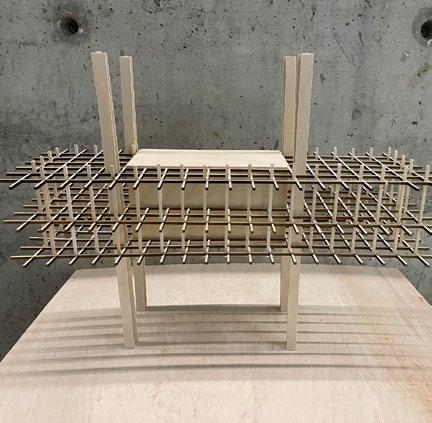
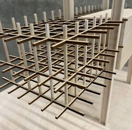
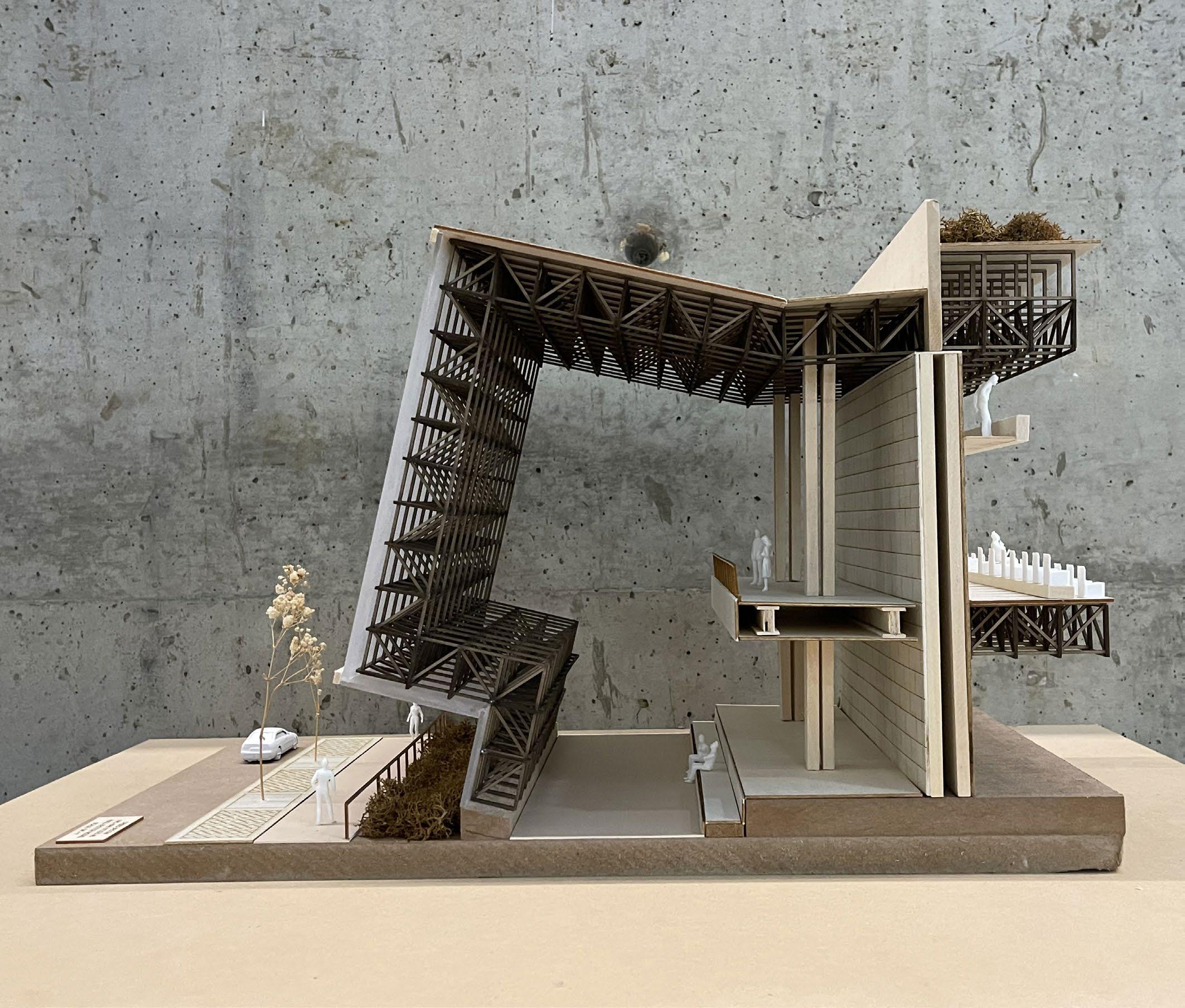
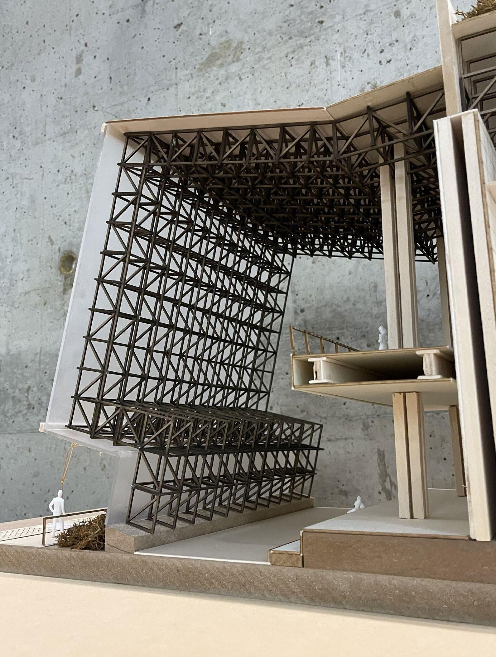
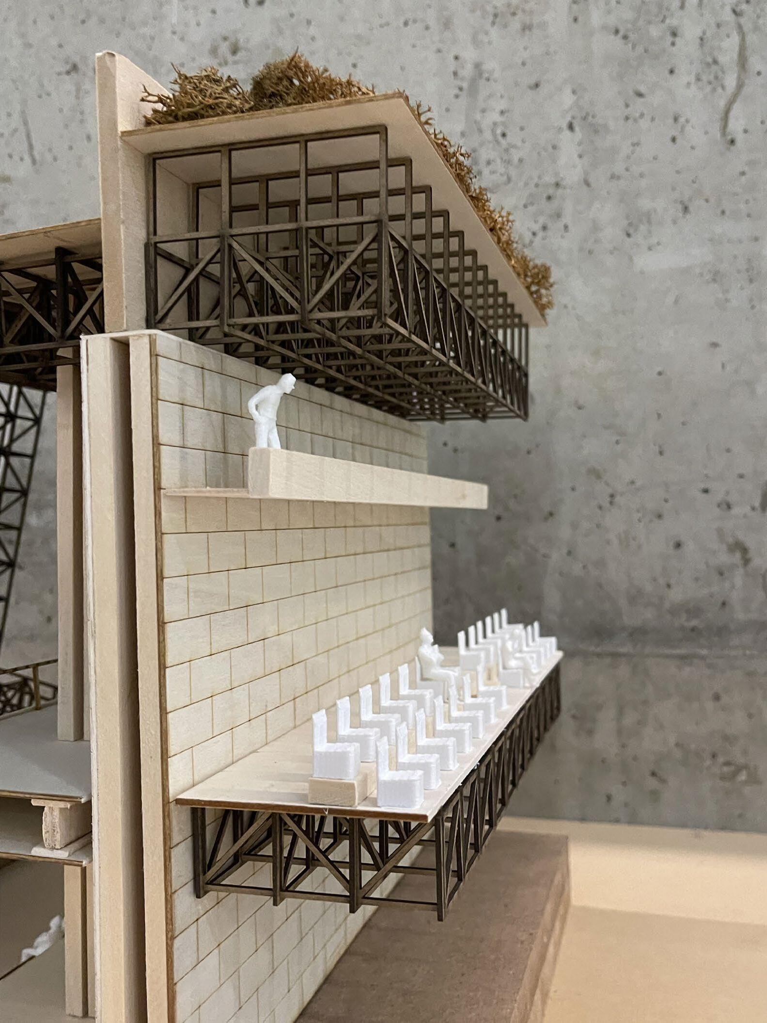
At the very base of design, the system of a grid is a fundamental part of every design process and detail-oriented project. The grid is ideal when trying to understand the relationships between spatial qualities and the building components that help try to define such nature. It becomes the most basic starting point when beginning design, especially when designing in a predefined area such as an infill site. Aside from the basics of the grid, this geometric system is very common to costal areas. Gulfport, MS has a particularly rich history of the seafood industry, as it was once crowned “Seafood Capital of the World.” The fundamental elements to this fishing industry: grid-patterned nets that shrimping boats use to harvest various kinds of seafood species. Bringing this idea of the grid into concept, I envision this grid-like structure to serve as more of an experience rather than a structure. The grid enables users to feel as if they are inside this “cage” like structure, and at a smaller scale can be used as a directional quality inside a large program such as a black box theater. The grid structure is split into two separate levels, giving both two-level entry points to the top theater and two points of visual interaction between the user and the street. This grid structure is raided, supported solely by four large wide-flanged steel beams. These beams are offset from the outer edges of the grid structure, creating a cantilevered space that serves as the point of entry/landing for the lobby, as well as a corridor space on the left side that serves as a directional quality both vertically and horizontally. This structure is ideally exposed both to the street façade of the building, as well as the roof of the lobby area.
Base Structure
GroundPlane
PROGRAM SCENARIO 2
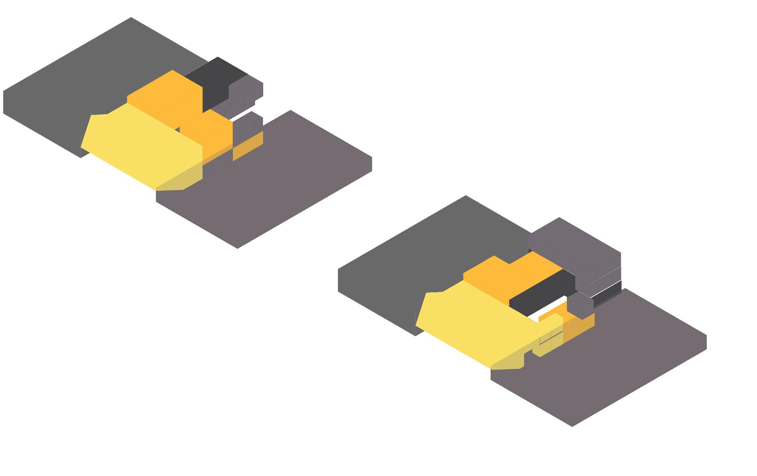
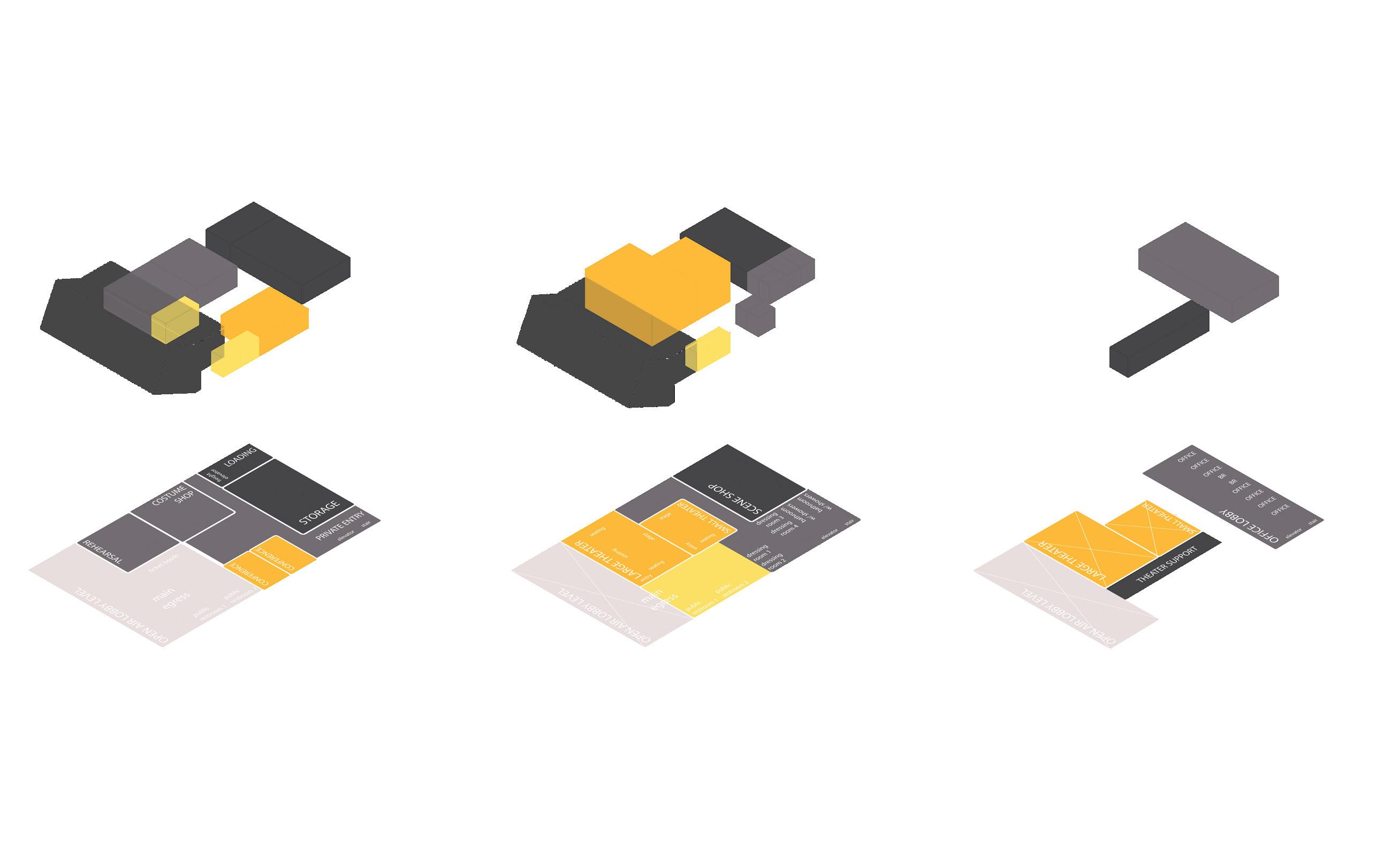
This program feautres three total levels that give administration the ability to have private offices with sunlight access by having them on the third level. This allows for admin to have their own seperate entrance around the backside, as performers would also have this amenity. Notable features on the ground level are the rehearsal space and the costume shop. With the idea of having a celebrated structure, this program also highlights the structure behind how performances are facilitated and are able to happen. I believe there is beauty behind exposing the bones of a performance, and allowing users to experience a small piece of how these performances are structured. By placing these two programic elements on the lower level, the theaters begin to reside on the second level, which allows for them to reside with the theater support, scene shop, and performer
rooms.
support
OPEN AIR LOBBY LEVEL SCENE SHOP LARGE THEATER SMALL THEATER LOADING STORAGE OPEN AIR LOBBY LEVEL OPEN AIR LOBBY LEVEL OFFICE LOBBY OFFICE OFFICE OFFICE OFFICE OFFICE OFFICE OFFICE BR BR COSTUME SHOP REHEARSAL CONFERENCE CONFERENCE public restroom 1 public restroom 2 main egress dressing room 1 dressing room 2 dressing room 3 dressing room 4 bathroom w/ showers bathroom w/ showers elevator stair public restroom 1 public restroom 2 main egress LARGE THEATER SMALL THEATER elevator stair THEATER SUPPORT stage stage seating seating seating seating entry entry PRIVATE ENTRY elevator stair freight elevator ticket booth THEATER LOBBY BOX OFFICE PUBLIC RESTROOMS OFFICE LOBBY OFFICES OFFICE RESTROOMS 4000 200 CODE 500 150 CODE CONFERENCE ROOM CONFERENCE ROOM 450 175 LARGE THEATER SMALL THEATER REHEARSAL ROOM COSTUME SHOP SCENE SHOP STORAGE 2500 1200 800 800 2500 1200 DRESSING ROOM (2) DRESSING ROOM (2) RESTROOMS SHOWER FACILITY LAUNDRY LOADING AREA 100 200 CODE 80 100 400 CUSTODIAL STORAGE CUSTODIAL ROOM 150 50 LARGE THEATER SMALL THEATER THEATER LOBBY
SHOWERFACILITY LAUNDRY
DRESSINGROOM(2) DRESSINGROOM(2) RESTROOMS
LOADINGAREA CUSTODIALSTORAGE CUSTODIALROOM
STORAGE OFFICELOBBY OFFICES OFFICERESTROOMS
SCENESHOP elevator restroom restroom office conference ticket elevator shop elevator storage shop locker restroom restroom restroom office conference ticket
REHEARSALROOM PUBLICRESTROOMSBOXOFFICE
CONFERENCEROOM CONFERENCEROOM COSTUMESHOP
02 03 04 01 00
schematic design
creed broom | academic portfolio | spring 2024
SCHEMATIC GOALS
With the idea of promoting a suspension of disbelief through the use of an expressive steel structure, there were several key concepts this project set to project.
• a structure that is the first thing you experience, something you can experience throughout the building, and the last thing you experience when you leave
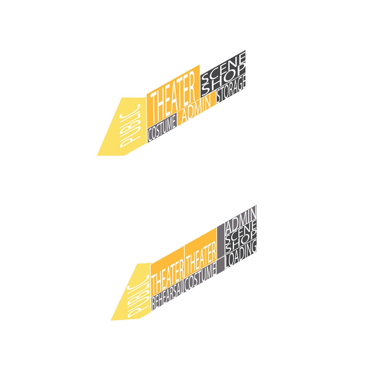
• like exposing the bones of this building (structure), exposing the bones to how a theater is held together: done through bringing costume shop and rehearsal studio open to street level
• using steel extrusions to create several threshold moments that promote the transition into this alternate reality
SCHEMATIC DESIGN / PLANS
DN UP UP DN DN DN DN 1 1 A101 1 A102 2 3 4 5 D C 6 B 1 A www.autodesk.com/revit Scale Date Drawn By Checked By Project Number Consultant Address Address Address Phone Consultant Address Address Address Phone Consultant Address Address Address Phone Consultant Address Address Address Phone Consultant Address Address Address Phone A106 Unnamed Owner Project No. Description
GROUND LEVEL SCALE: 1/16” = 1’ N LEGEND 1. ticket booth 2. rehearsal studio 3. costume shop 4. storage 5. loading 6. custodial room 7. custodial storage 8. mechanical 8 7 6 5 4 3 2 8 1 25th AVE. A109 1
SCHEMATIC DESIGN / PLANS
DN UP DN 1 A101 1 A102 2 3 4 5 D C 6 B 1 A www.autodesk.com/revit Scale Date Drawn By Checked By Project Number Consultant Address Address Address Phone Consultant Address Address Address Phone Consultant Address Address Address Phone Consultant Address Address Address Phone Consultant Address Address Address Phone A107 Unnamed Owner Project No. Description
SECOND LEVEL SCALE: 1/16” = 1’ N LEGEND 1. large black box 2. small black box 3. bar 4. scene shop 5. laundry 6. dressing rooms (150 sqft each) 7. mechanical 1 2 7 5 6 7 6 6 6 4 3
SCHEMATIC DESIGN / PLANS
THIRD LEVEL
SCALE: 1/16” = 1’
DN UP 1 A101 1 A102 2 3 4 5 D C 6 B 1 A Date Drawn Checked Project No.
N LEGEND 1. office lobby 2. offices (150 sqft each) 3. conference rooms 4. small theater tech room 5. large theater tech room/catwalks 6. mechanical 4 5 3 3 2 2 2 2 2 2 6 1
LONGITUDINAL SECTION SCALE: 1/8” = 1’ 75’ 13’ 6” 28’ Level 1 Level 2 Level 3 Roof Theater Roof 3’ 0” 19’ 0” 35’ 0” 51’ 0” 55’ 0”
WEST ELEVATION SCALE: 1/4” = 1’
SCHEMATIC DESIGN / SECTIONS
TRANSVERSE SECTION SCALE: 1/8” = 1’ Level 1 Level 2 Level 3 Theater Roof 3’ 0” 19’ 0” 35’ 0” 55’ 0” 20’ 20’ 20’ 17’ 24’
ALLEY ELEVATION SCALE: 1/8” = 1’
03 04 05 02 01
building tectonics/code analysis
creed broom | academic portfolio | spring 2024
TECTONICS / DIPTYCH
ROOF
OVERHANG
54’ 0”
16’ 0”
WEST ELEVATION SCALE: 3/16” = 1’
WALL SECTION SCALE: 3/16” = 1’
1.
3. 6” INSULATION LAYER
4. 2” CONCRETE SLOPE
5. 10” REINFORCED CONCRETE ROOF SLAB 6. 7/8” ANCHOR BOLT
SCALE: 1” = 1’
1/2” ROOF MEMBRANE
2. WATERPROOFING MEMBRANE
7.
10. 3/4” ETFE PANEL 11. 316 STAINLESS STEEL SPIDER CONNECTOR 1 2 3 4 5 6 7 8 9 10 11 12 13
CANT STRIP 8. FLASHING W/ DRIP EDGE 9. ALUMINUM FIXED WINDOW HEAD
1. 3/4” ETFE PANEL 2. STEEL SPACE FRAME 3. 316 STAINLESS STEEL SPIDER CONNECTOR 4. ALUMINUM FIXED WINDOW HEAD 5. GUTTER FILTER 6. 8”
SCALE: 1” = 1’
TECTONICS / DETAIL 2
GUTTER 1 1 2 3 4 5 6
DEPTH
1. 3/4” ETFE PANEL
2. STEEL SPACE FRAME
3. ALUMINUM FIXED WINDOW HEAD
4. 7/8” ANCHOR BOLT
5. PRECAST BOND BEAM FILLED WITH CONCRETE FOR ANCHOR BOLTS
6. 8”x8”x16” CMU BLOCK
7. VAV RETURN DUCT
8. LIMESTONE PLASTER FINISH
9. CAISSON FOUNDATION
10. FLOW THROUGH PLANTER
11. UNDISTURBED GRADE
3 2 1 4 5 6 7 8 9 10 11
1/2” ROOF MEMBRANE
8’x12’ ETFE FACADE PANELS
6” RIGID INSULATION
6” CONCRETE ROOF DECKING
ENTIRE ROOF ASSEMBLY
ROOF FLASHING W/ DRIP EDGE
STEEL PLATE OPENING STRUCTURE
STEEL SPACE FRAME
8” DEPTH GUTTER
316 STAINLESS STEEL SPIDER CONNECTION
CMU SPACE FRAME BASE
EXPLODED WALL AXON
SCALE: 1/16” = 1’
CODE / EGRESS PLAN 3
DN UP UP DN DN EXIT 1 Door 374 Occ. 72” EXIT 4 Door 4 Occ. 72” EXIT 3 Door 58 Occ. 36” EXIT 5 Door 90 Occ. 72” EXIT 6 Door 142 Occ. 36” EXIT 2 Door 115 Occ. 36” Costume Shop 103 1,210 sqft Occ. Rehearsal 102 2,575 sqft 86 Occ. Lobby 101 5,508 sqft 374 Occ. Storage 104 1,100 sqft 4 Occ. Loading 105 702 sqft 2 Occ. CODE / EGRESS PLAN 1 40’ 48’ 22’ 8’ 8’ 46’ 12’ 43’ 18’ 10’ 33’ LEVEL 1 SCALE: 1/32” = 1’ FIRE-RATED ROOM DN DN EXIT 2 Door 115 Occ. 36” EXIT 3 Door 58 Occ. 36” EXIT 6 Door 142 Occ. 36” Lg. Theater 202 2,575 sqft 115 Occ. Sm. Theater 203 1,210 sqft 36 Occ. Costume Shop 103 1,210 sqft 4 Occ. Dress 205 120 sqft 2 Occ. Dress 206 120 sqft 2 Occ. Dress 207 120 sqft 2 Occ. Dress 208 120 sqft 2 Occ. CODE
33’ 25’ 36’ 22’ 20’ 34’ 18’ 30’ 39’ LEVEL 2 SCALE: 1/32” = 1’ FIRE-RATED ROOM DN EXIT 3 Door 58 Occ. 36” EXIT 6 Door 142 Occ. 36” Office 103 133 sqft Occ. Office 103 133 sqft Occ. Office 103 133 sqft Occ. Office 103 133 sqft Occ. Office 103 133 sqft Occ. Office 103 133 sqft Occ. Conference 103 210 sqft 14 Occ. Conference 103 210 sqft 14 Occ. Office Lobby 103 567 sqft 4 Occ.
/ EGRESS PLAN 2
11’ 11’ 11’ 11’ 11’ 11’ 21’ 14’ 27’ LEVEL 3 SCALE: 1/32” = 1’ FIRE-RATED ROOM CODE / ADA PLANS 5' 2" 5' 2" 16' 3" 14' 4" 12' 4" 12' 4" 5' 8" 4’ 0” 7’ 0” 4’ 0” 3’ 0” ADA Seating ADA ADA ADA ADA ADA ADA LARGE THEATER PLAN SCALE: 1/8” = 1’ BATHROOM PLAN SCALE: 3/4” = 1’ OCCUPANT LOAD WORKSHEET NAME: Creed Broom DATE: 3/22/2024 ROOM # ROOM NAME FUNCTION Lobby Assembly without fixed seats Large Theater Assembly without fixed seats Small Theater Assembly without fixed seats Scene Shop Group H-5 fabrication/manufa Costume Shop Mercantile (Storage,Stock) Dressing Room 1 Locker Rooms Dressing Room 2 Locker Rooms Dressing Room 3 Locker Rooms Dressing Room 4 Locker Rooms Laundry Locker Rooms Loading Area Accessory Storage Area Storage Accessory Storage Area Mechanical Accessory Storage Area Conference Room 1 Assembly w/o fixed seating Conference Room 2 Assembly w/o fixed seating Office Lobby Buisness Area Office 1 Buisness Area Office 2 Buisness Area Office 3 Buisness Area Office 4 Buisness Area Office 5 Buisness Area Office 6 Buisness Area Office 7 Buisness Area Rehersal Studio Assembly w/o fixed seating APPLICABLE CODES YEAR IBC International Building Code 2018 D. Type of Construction: IIB G. Plumbing Fixtures: Table 2902.1 ICC / ANSI 117.1 2009 Minimum Number of Required Plumbing Fixtures: International Code Council (ICC) Occupancy A1 American National Standard Institute (ANSI) Table 601 Water Closets: Fire-Resistance Rating Requirements for Building Elements (hrs): Lavatories: Building Element Hrs Bathtubs or Showers: A. Occupancy Group(s): A1 B F1 S2 - Structural Frame 0 Drinking Fountains: Change in Use: Yes Mixed Occupancy: Yes Exterior Bearing Walls 0 Other: Interior Bearing Walls 0 Complete this portion for Mixed-Use Occupancies Nonbearing Walls and Interior Partitions 0 Secondary Occupancy B B. Special Use and Occupancy (eg. High Rise, Covered Mall): Yes Floor Construction (supporting beams and joists) 0 Water Closets: Roof (beams and joists) 0 Lavatories: Bathtubs or Showers: C. General Building Height & Areas: Table 602 Drinking Fountains: Allowable Height 75 ft Table 504.3 Fire Resistance Rating Other: Allowable Stories 3 Table 504.4 Requirements for Exterior Walls based on the fire separation distance (in hours): North South East West Automatic Sprinkler System Increase: Rating in hours 0 0 0 0 H. Notes and Other Applicable Code Information: Building Height Increase: 20 ft Table 504.3 Distance in feet x' x' x' x' Number of Stories Increase: 0 Table 504.3 Allowable Area Table 506.2 E. Fire Protection Systems: Allowable Area (Aa) 25,500 sq. ft. Automatic Sprinkler Systems: IBC 903.2 Equation 5-1 Aa = At + (NS × If) For single story Is an Auto. Sprinkler Sys. required for your occupant group? Yes Equation 5-2 Aa = [At + (NS × If)] × Sa For multi-story Are you providing an Auto. Sprinkler Sys.? Yes At NS If F. Means of Egress: Sa Occupant Load Calculations: Table 1004.1.2 Actual Building Stats Actual Total Building Stories 3 Actual Total Height ft Total Building Occupancy = 678 Actual Total Building Area sf Main Level sf Means of Egress Sizing: IBC 1005 Second Level sf Stairways: IBC 1005.3.Occupant Load * 0.3in. = 203.4 in Third Level sf Other: IBC 1005.3.2 Occupant Load * 0.2in. = 135.6 in Fourth Level sf Fifth Level sf Stair Width Provided = 190 in Sixth Level sf Corridor Width Provided = 140 in Exits from Stories: IBC 1021.2 Minimum Number of Required Exits 2 Number of Exits Provided = 3 58 12,600 400 15,230 28,230 See IBC 602.2, 602.3, 602.4, 602.5 IBC Chapter IBC Chapter 10 Male:2 Female:2 n/a Male:2 Female:2 Male:2 Female:2 Male:2 Female:2 IBC Chapter *room sf occupant load factor room occupant load *Add all room occupant loads together to generate Total Building Occupancy. IBC Chapter 29 IBC Chapter IBC Chapter IBC Chapter CODE ANALYSIS WORKSHEET Project Name: Preparer: Date: Gulport Theater Creed Broom 3/22/24
SQUARE FOOTAGE NET/GROSS OCC. LOAD FACTOR 5,608 NET 15 374 2,575 - 7 115 1,210 - 7 36 1,500 GROSS 200 8 1,210 GROSS 300 4 120 GROSS 50 2 120 GROSS 50 2 120 GROSS 50 2 120 GROSS 50 2 80 GROSS 50 2 702 GROSS 300 2 1,100 GROSS 300 4 80 GROSS 300 0 210 NET 15 14 210 NET 15 14 567 NET 150 4 133 NET 150 1 133 NET 150 1 133 NET 150 1 133 NET 150 1 133 NET 150 1 133 NET 150 1 133 NET 150 1 2,575 NET 30 86 5 0 5 0 5 0 5 0 5 0 5 0 5 0 5 0 5 0 5 0 5 0 5 0 5 0 5 0 OCCUPANCY LOAD SCALE: 1/16” = 1’ SCALE: 1/16” = 1’ SCALE: 1/16” = 1’
CODE / EGRESS AND ANALYSIS
04 05 03 02
resiliency measures
creed broom | academic portfolio | spring 2024
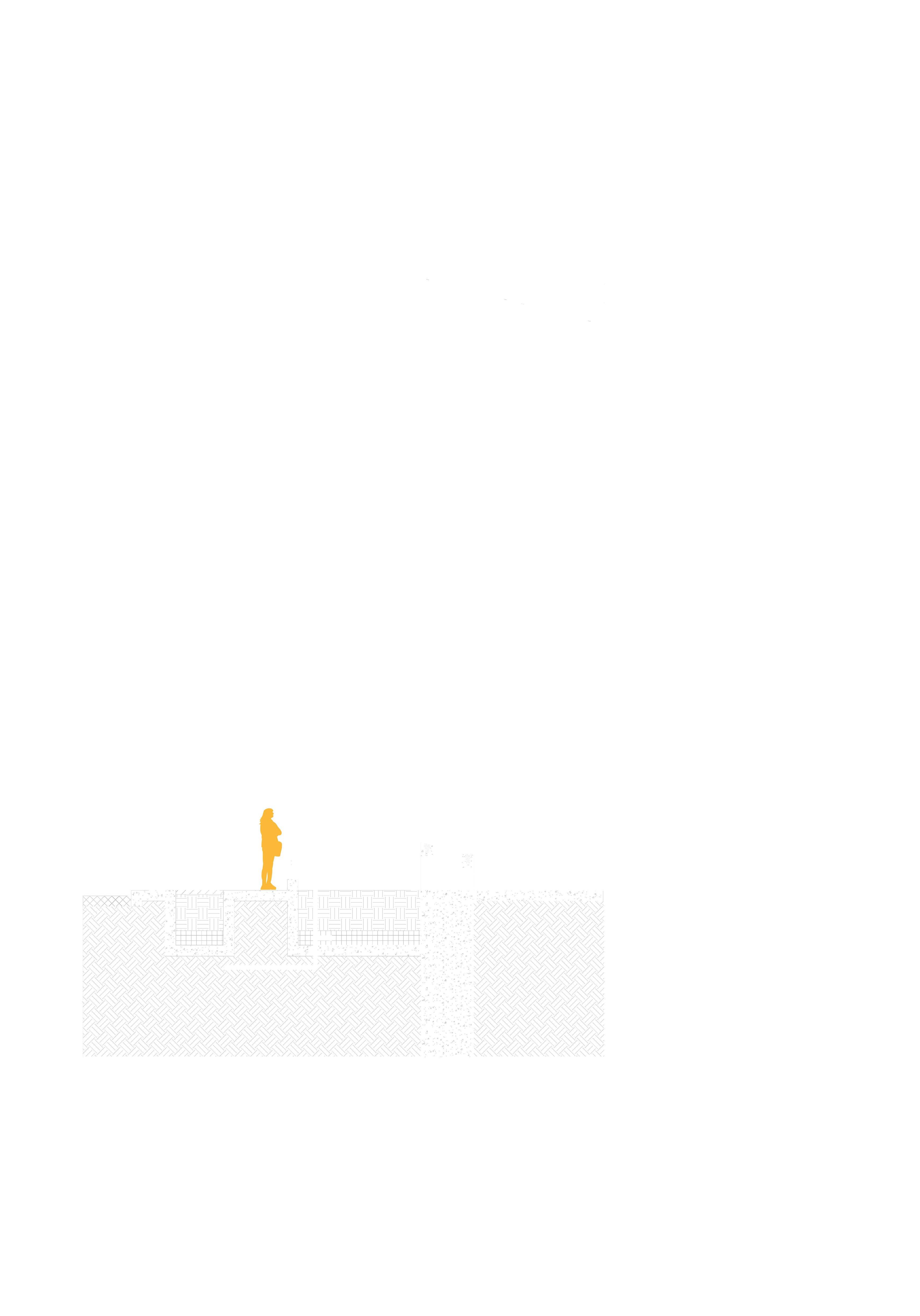
CAISSON FOUNDATION
STEEL SPACE FRAME
4’X4’ SPACING
1 3
4: 1’x1’ HSS STEEL HOLLOW COLUMNS FORMING ONE LARGE COLUMN
COASTAL RESILIENCY
After the effects of hurricane Katrina, costal resiliency is always a priority for design. Here are a few measures this project takes towards adressing a resilient future.
• a structure that is resistant towards hurricane conditions
• an elevated program and structure that exceeds the 25ft elevation of Katrina flood levels
• bio-retention swells and green roofs to help midigate rainwater
• materials that are low in energy that also withstand hurricane forces
growing medium moisture-retention layer aeration layer thermal insulation drainage layer concrete roof overflow drain waterproof membrane gravel growing medium downspout waterproof membrane overflow drain growing medium gravel
1. FLOW-THROUGH DETAIL SCALE: 1/4” = 1’
FLOW-THROUGH DETAIL SCALE: 1/4” = 1’ 1 3 2
2. GREEN ROOF DETAIL SCALE: 1/2” = 1’ 3.
ENVIRONMENTAL SYSTEMS / VAV SYSTEM
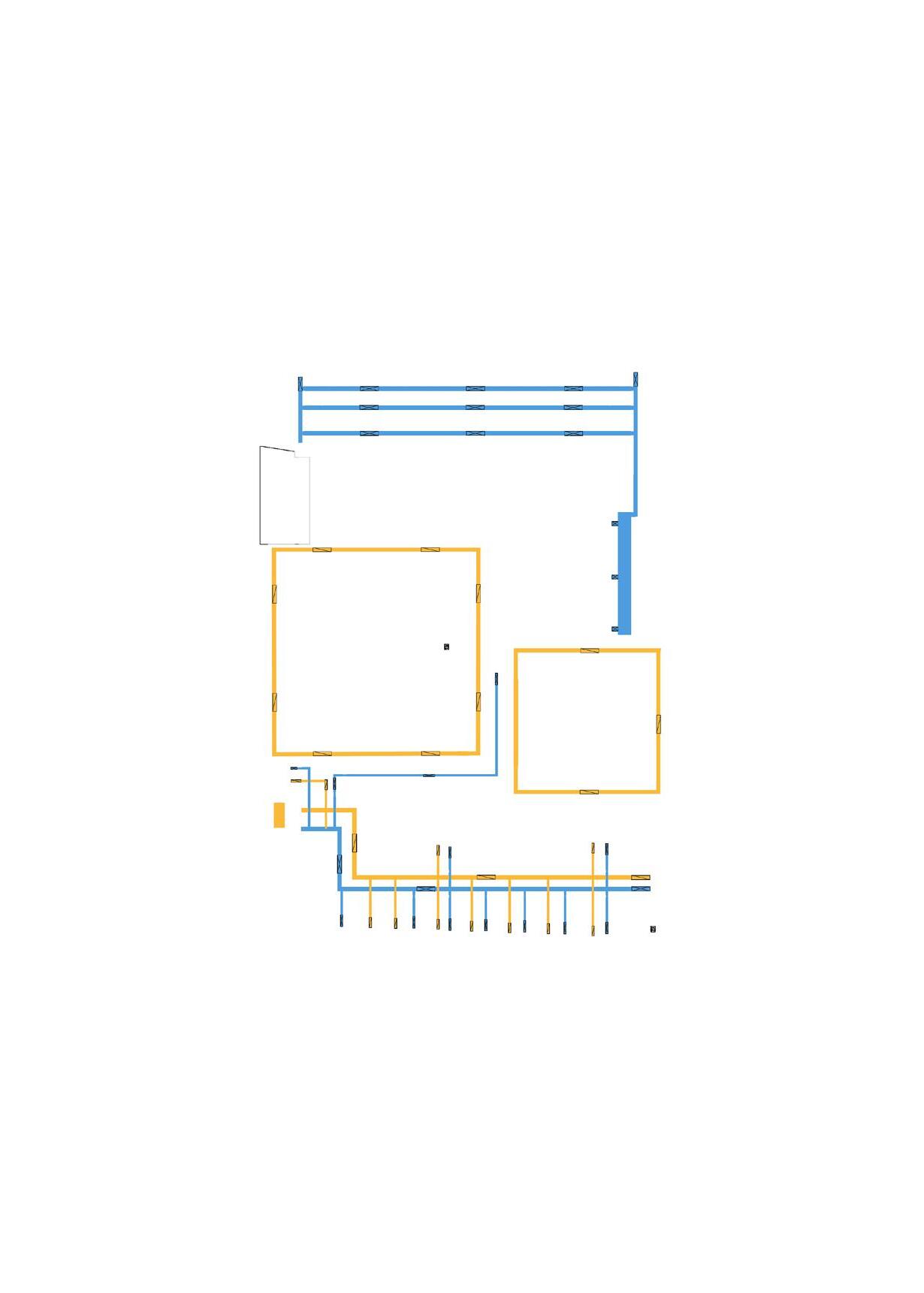
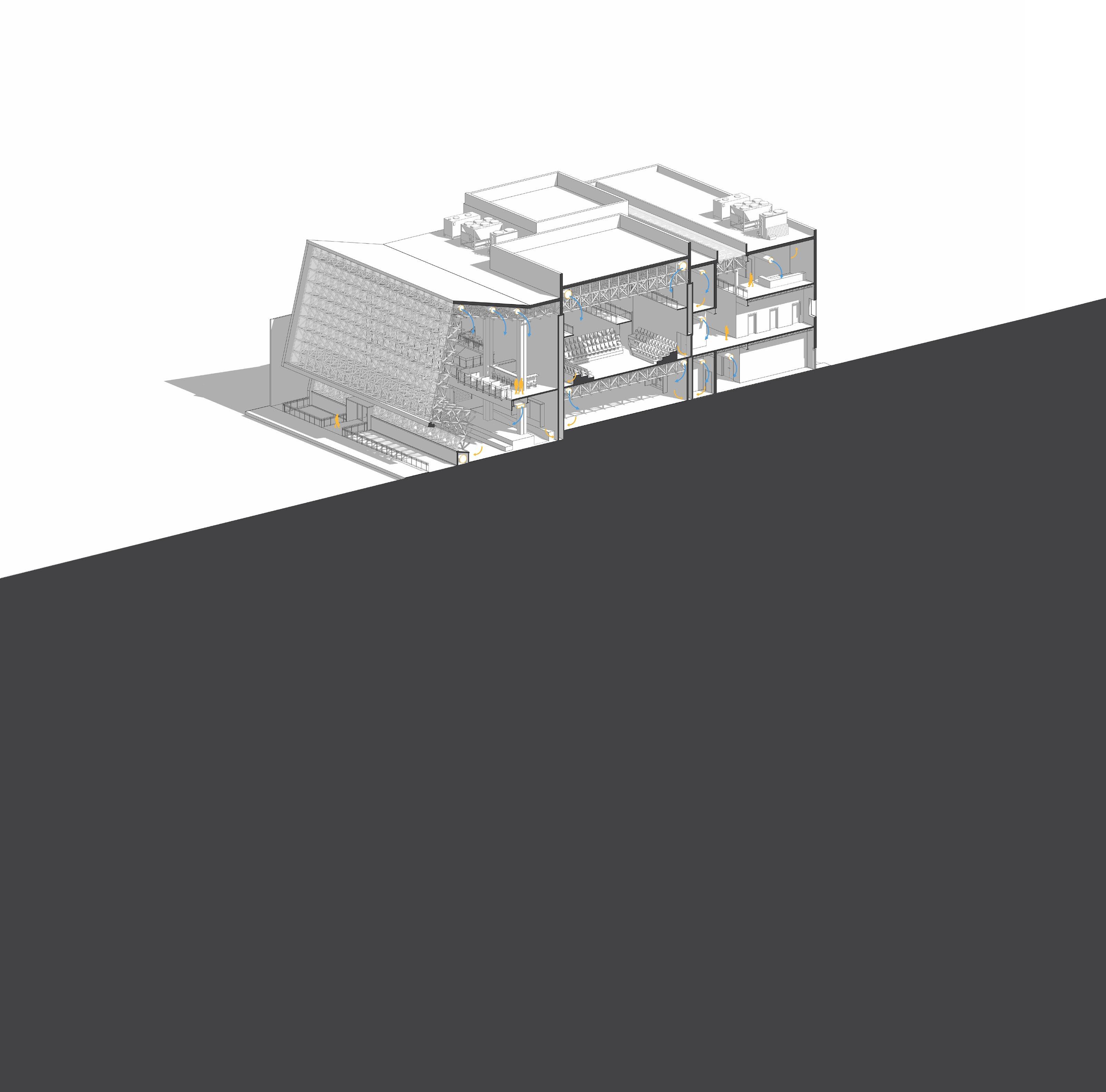
1 2 3 1 2 3 1. condensing boiler 2. cooling tower (60 ton) 3. chiller (60 ton) return vent supply vent supply duct return duct air-handler LEVEL 1 HVAC PLAN SCALE: 1/64” = 1’ LEVEL 2 HVAC PLAN SCALE: 1/64” = 1’ LEVEL 3 HVAC PLAN SCALE: 1/64” = 1’
EE + CARBON / MATERIALS
8”x8”x16” structural cmu block wall, sourced from DECRASTONE in Tupelo, MS
4’x8’ etfe panels, sourced from DOMER in New Jersey 1
steel space frame constructed with 4”x4” hollow tubes sourced from STRUCTURAL STEEL SERVICES in Meridian, MS
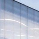
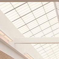
8’x12’ kalwall panel skyroof system, sourced from KALWALL in Manchester, NH
fine-grit grey lime plaster against cmu block partition wall, sourced from ARCUS STONE in San Marcos, TX extensive garden roof system, sourced from HYRDROTECH in Chicago, IL
2 3 4 5
6 7 1 2 3 4 5 6 7 40 W 18,697,003 hours 2,692,367 MJ EE TOTAL 11,514,591 hours 1,016,272 hours 4,367,326 hours 13,809 hours 1,760,031 hours n/a 24,972 hours
4’x8’ bleair limestone panel sourced from STONEPLY in Greenville, TX
(9.49 MJ/ton-mile) (9.49 MJ/ton-mile) (9.49 MJ/ton-mile) (2.19 MJ/ton-mile) (2.19 MJ/ton-mile) (2.19 MJ/ton-mile) (1.37 MJ/ton-mile) (1.37 MJ/ton-mile) (1.37 MJ/ton-mile) (0.39 MJ/ton-mile) (0.39 MJ/ton-mile) (0.39 MJ/ton-mile) (0.37 MJ/ton-mile) (0.37 MJ/ton-mile) (0.37 MJ/ton-mile) (0.23 MJ/ton-mile) (0.23 MJ/ton-mile) (0.23 MJ/ton-mile) (total EE / 3.6 MJ) (total EE 3.6 MJ) (total EE 3.6 MJ) (9.49 MJ/ton-mile) (9.49 MJ/ton-mile) (9.49 MJ/ton-mile) (2.19 MJ/ton-mile) (2.19 MJ/ton-mile) (2.19 MJ/ton-mile) (1.37 MJ/ton-mile) (1.37 MJ/ton-mile) (1.37 MJ/ton-mile) (0.39 MJ/ton-mile) (0.39 MJ/ton-mile) (0.39 MJ/ton-mile) (0.37 MJ/ton-mile) (0.37 MJ/ton-mile) (0.37 MJ/ton-mile) (0.23 MJ/ton-mile) (0.23 MJ/ton-mile) (0.23 MJ/ton-mile) (total EE / 3.6 MJ) (total EE 3.6 MJ) (total EE 3.6 MJ)
05 04 03
physical models
creed broom | academic portfolio | spring 2024
thank you