


East Industrial Park Area Structure Plan BYLAW 1342–23
i East Industrial Park Area Structure Plan East Industrial Park Area Structure Plan Table of Contents 1.0Location,Background&Purpose 1 1.1Location 1 1.2IDPBackground&ShadowPlanArea 3 1.3RegionalEconomicDevelopment 3 2.0LegislativeContext 4 2.1MunicipalGovernmentAct 4 2.2ProvincialLandUsePolicies 5 2.3IntermunicipalDevelopmentPlan 5 2.4MunicipalDevelopmentPlan 5 3.0ExistingFeatures 7 3.1NaturalEnvironment 7 3.2BuiltEnvironment 11 4.0FutureLandUseConcept 16 4.1FutureLandUseConcept 16 4.2Industrial/Commercial 19 4.3Agricultural 20 4.4SequenceofDevelopment 20 4.5ReserveLands 21 5.0TransportationNetwork 23 5.1LocalRoads 23 5.2AccessManagement 23 5.3Off-SiteImprovements 24 5.4Highway16/881Interchange 24 5.5CNRailway 25 5.6AdditionalAnalyses 25 6.0Servicing 27 6.1Water 27 6.2Wastewater 28 6.3StormwaterManagement 29 6.4ShallowUtilities 31 BYLAW 1342–23
ii Table of Contents | County of Minburn/Village of Mannville 7.0Earthworks 34 8.0Interpretation&Implementation 37 8.1Interpretation 37 8.2Monitoring&Amendment 38 9.0Policies 39 9.1General 39 9.2Environment 40 9.3Industrial 40 9.4Agricultural 41 9.5SequenceofDevelopment 41 9.6ReserveLands 41 9.7Transportation 42 9.8Services 44 9.9Lighting,Landscaping&Screening 45 9.10Implementation 45 FIGURE1 Location&PlanBoundary 2 FIGURE2 ExistingFeatures:NaturalEnvironment 10 FIGURE3 ExistingFeatures:BuiltEnvironment 12 FIGURE4 ExistingFeatures:LandUse 14 FIGURE5 FutureLandUseConcept 18 FIGURE6 SequenceofDevelopment 22 FIGURE7 TransportationNetwork 26 FIGURE8 Servicing 30 FIGURE9AStormWater:Scenario1 32 FIGURE9B StormWater:Scenario2 33
Tables Appendices A AppendixABiophysicalReport B AppendixBGeotechnicalReport C AppendixCLagoonAssessment D AppendixDTransportationReview E AppendixEServicingBrief F AppendixFStormwaterManagementPlan G AppendixGCertificatesofTitle(redacted) Prepared by: Red Willow Planning All photos: © Davin Gegolick
List of Maps List of
1.0 Location, Background & Purpose
1.1 Location
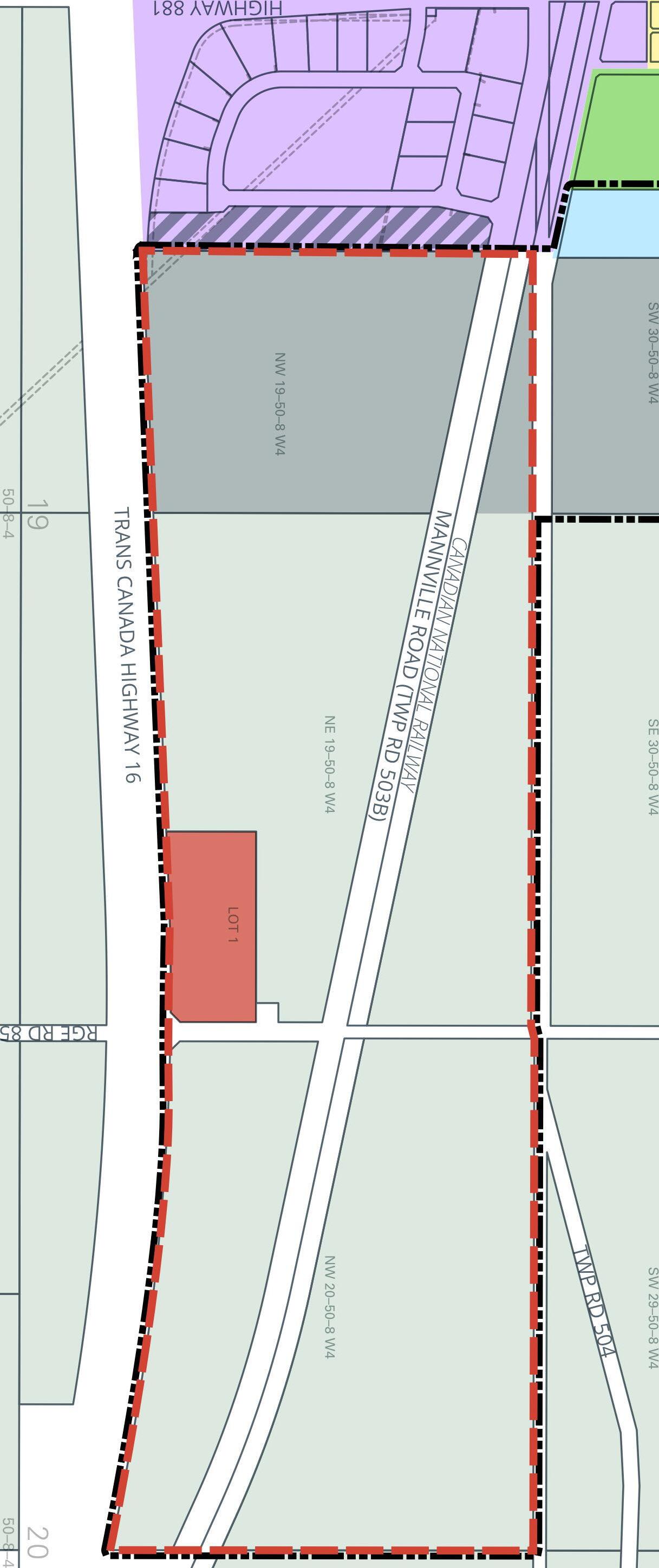
The East Industrial Park Area Structure Plan (ASP) study area is located immediately east of the Village of Mannville in the County of Minburn, Alberta, Canada comprising seven parcels:
1. NW 20-50-8-4
2. North half 19-50-8-4 (north of the CN Railway)
3. NW 19-50-8-4 (south of the CN Railway)
4. NE 19-50-8-4 (south of the CN Railway)
5. Lot 1, Block 1, Plan 062 6818
6. Lot 1, Block 1, Plan 212 2252
7. Block A, Plan 852 0860 (Shadow Plan lands in the Village of Mannville)
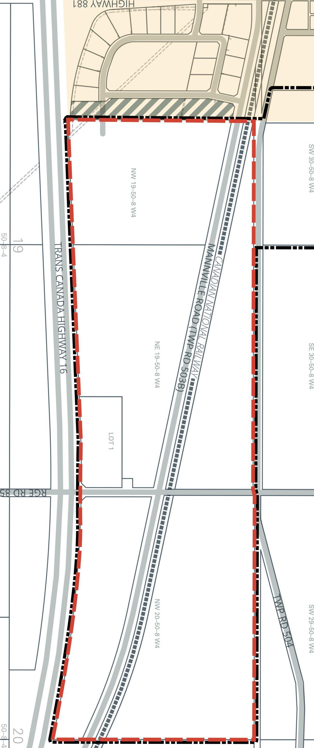
The ASP location is also adjacent to the Yellowhead, Highway 16. See Figure 1 for location and context map.
1 East Industrial Park Area Structure Plan

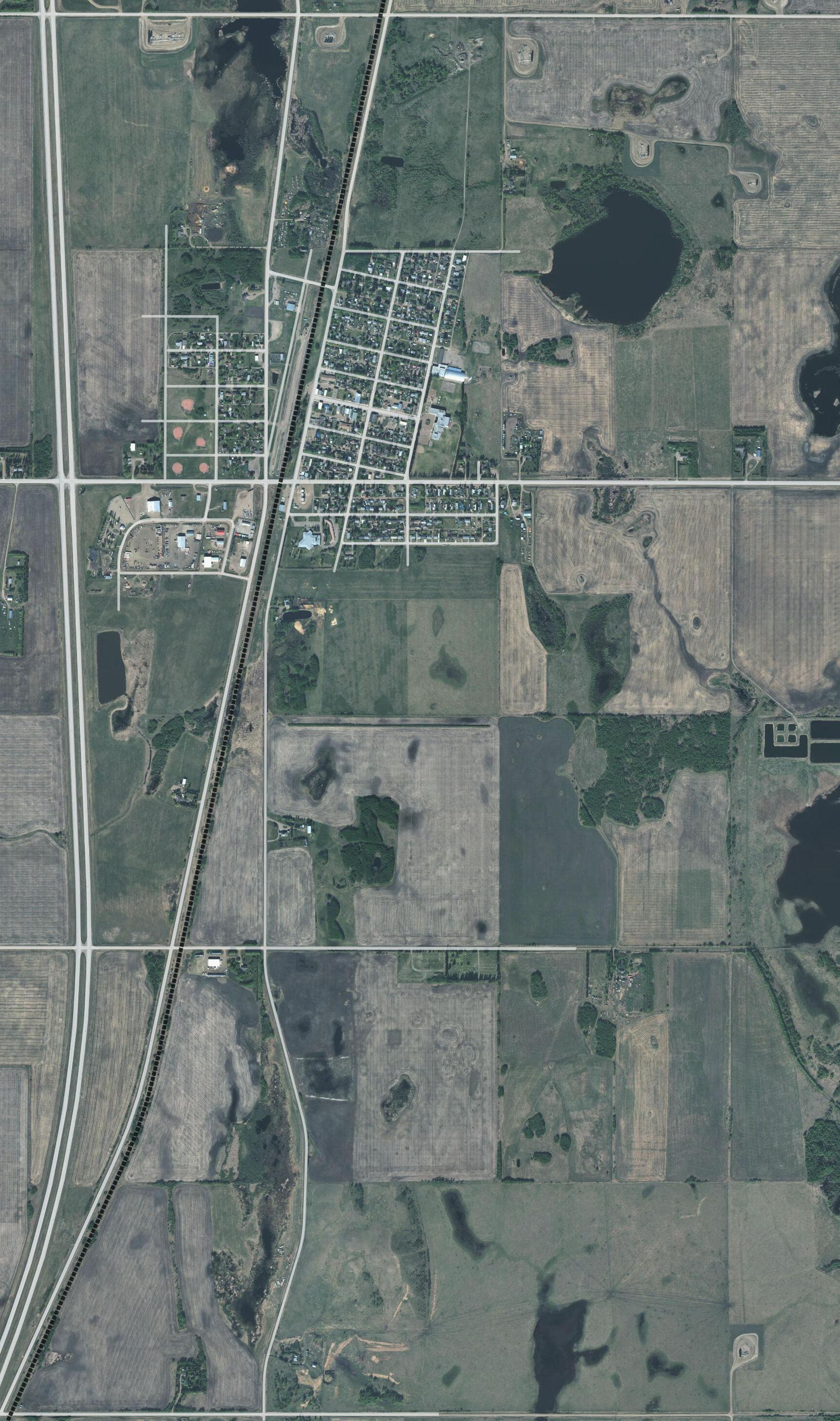


2 Background, Purpose & Scope | County of Minburn/Village of Mannville TRANS CANADA HIGHWAY 16 MANNVILLE ROAD (TWP RD 503B) TWP RD 504 HIGHWAY881 RGE RD85 RGE RD91 RGE RD84 20 50–8–4 29 50–8–4 19 50–8–4 NE 19–50–8 W4 NW 19–50–8 W4 NW 20–50–8 W4 24 50–9–4 25 50–9–4 30 50–8–4 631 619 881 870 857 16 16 36 16A VEGREVILLE Mannville Innisfree Ranfurly Lavoy COUNTY OF TWO HILLS BEAVER COUNTY M.D. OFWAINWRIGHT COUNTYOFVERMILIONRIVER LAMONTCOUNTY COUNTY OF MINBURN NO. 27 FIGURE 1 LOCATION & PLAN BOUNDARY COUNTY OF MINBURN / VILLAGE OF MANNVILLE MANNVILLE EAST INDUSTRIAL PARK AREA STRUCTURE PLAN LEGEND IDP Boundary Plan Boundary Shadow Plan Area Village of Mannville Canadian National Railway ACE Regional Waterline 200 0 1:20,000 400 m
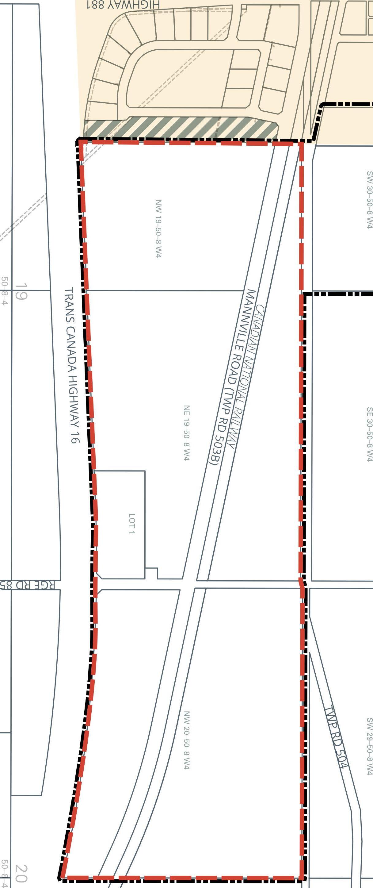
1.2 IDPBackground&ShadowPlan Area
Section 6.6 of the Village of Mannville – County of Minburn Intermunicipal Development Plan (IDP) speaks to the preparation of joint area structure plans in the locations shown in the IDP’s Figure 7 Future Land Use & Joint Planning Areas. There are two areas identified, one to the west of the Village and the other to the east. The east area is addressed by this ASP.
Additionally, the County and the Village discussed their mutual interest in coordinating development of a strip of undeveloped land within the Village’s existing industrial park immediately west of the ASP boundary. Consequently, a ‘Shadow Plan’ area was established for discussion purposes only (Figure 1), and no policies in this ASP are applied to the Shadow Plan area.
1.3 RegionalEconomicDevelopment
The mutual interest described above relates to the desire to jointly promote the area for non-residential development to investors. Coordination of development, and servicing if the parties jointly agree, will support regional economic development.
That being said, the parties wish to avoid competition with each other. The County supports the Village’s desire to develop its existing supply of serviceable non-residential land in the Shadow Plan area prior to the County developing similarly sized and serviced lots within the ASP boundary. The sequence of development, discussed in more detail in section 4.6 below, demonstrates this support.
3 East Industrial Park Area Structure Plan

2.0 Legislative Context
2.1 MunicipalGovernmentAct
The Municipal Government Act (MGA) in s. 633 states the purpose of an Area Structure Plan (ASP) is to provide a framework for future subsequent subdivision and development of an area of land. Further, the MGA directs that an ASP:
1. Must describe
a. The sequence of development proposed for an area,
b. The land uses proposed for an area either generally or specifically,
c. The density of population proposed for the area,
d. The general location of major transportation routes and public utilities, and
2. May contain any other matters, including matters relating to reserves, as the council considers necessary.
4 Legislative Context | County of Minburn/Village of Mannville
2.2 ProvincialLandUsePolicies
Section 618.4(1) of the MGA requires that every statutory plan be consistent with the Provincial Land Use Policies established by Order in Council 522/96. This ASP has been prepared in consideration of the Provincial Land Use Policies.
2.3 IntermunicipalDevelopment Plan
The IDP requires that the joint ASPs are prepared by a Registered Professional Planner, are consistent with the requirements of the MGA and pursuant to the General Terms of Reference for the Preparation of a Conceptual Scheme or Area Structure Plan, found in Appendix B of the IDP. This ASP complies with all three of these requirements.
2.4 MunicipalDevelopmentPlan
The Municipal Development Plan (MDP) identifies specific initiatives in Section 1.5, including the preparation of joint planning initiatives within existing intermunicipal development plans, including that between the Village of Mannville and the County of Minburn.
Section 3.4 provides objectives and policies for commercial and industrial lands. Key policies that influence and are upheld by this ASP include:
3.4.3 The County shall use the following site criteria in determining rural industrial site suitability for the intended use:
a. has stable, well drained soils;
b. has (or will have) safe and convenient access to public roads built to County standards;
c. located where rail access exists or could be provided if required;
d. has necessary services and utilities available if required;
5 East Industrial Park Area Structure Plan
e. has suitable local climate conditions, especially for noxious industries;
f. has an appropriate buffer from land designated for AR-Acreage Residential District when considering a subdivision or development application for rural industry;
g. is suitably located in relation to waterbodies; and
h. is not located within significant scenic, recreational or open space areas
3.4.6 The County shall encourage the creation of industrial parks in order to provide industrial development opportunities in a manner that concentrates industrial development, rather than scatters it, minimizes conflicts with adjacent land uses and facilitates the economic provision of services (including roads). The County shall encourage new industrial developments to locate in one of the following industrial parks and locations:
a. East Industrial Park;
b. West Industrial Park;
c. Crossroads Industrial Park;
d. Within existing hamlets in accordance with the existing ASPs; and
e. Within intermunicipal fringe areas in accordance with the IDPs.
3.4.16 The County may allow convenience retail services to locate in industrial parks, acreage residential developments or manufactured home communities where adequate services do not exist nearby. The size of commercial outlets shall be relative to the immediate population being served.
3.4.17 The County may allow commercial activities in industrial parks where the development is ancillary to the industrial use on that parcel.
3.4.26 The County shall ensure highway commercial uses maintain the functional integrity of adjacent highways through the use of service road systems or controlled highway access points that are approved by Alberta Transportation, or the County Operations Department.
6 Legislative Context | County of Minburn/Village of Mannville
3.0 Existing Features
3.1 NaturalEnvironment
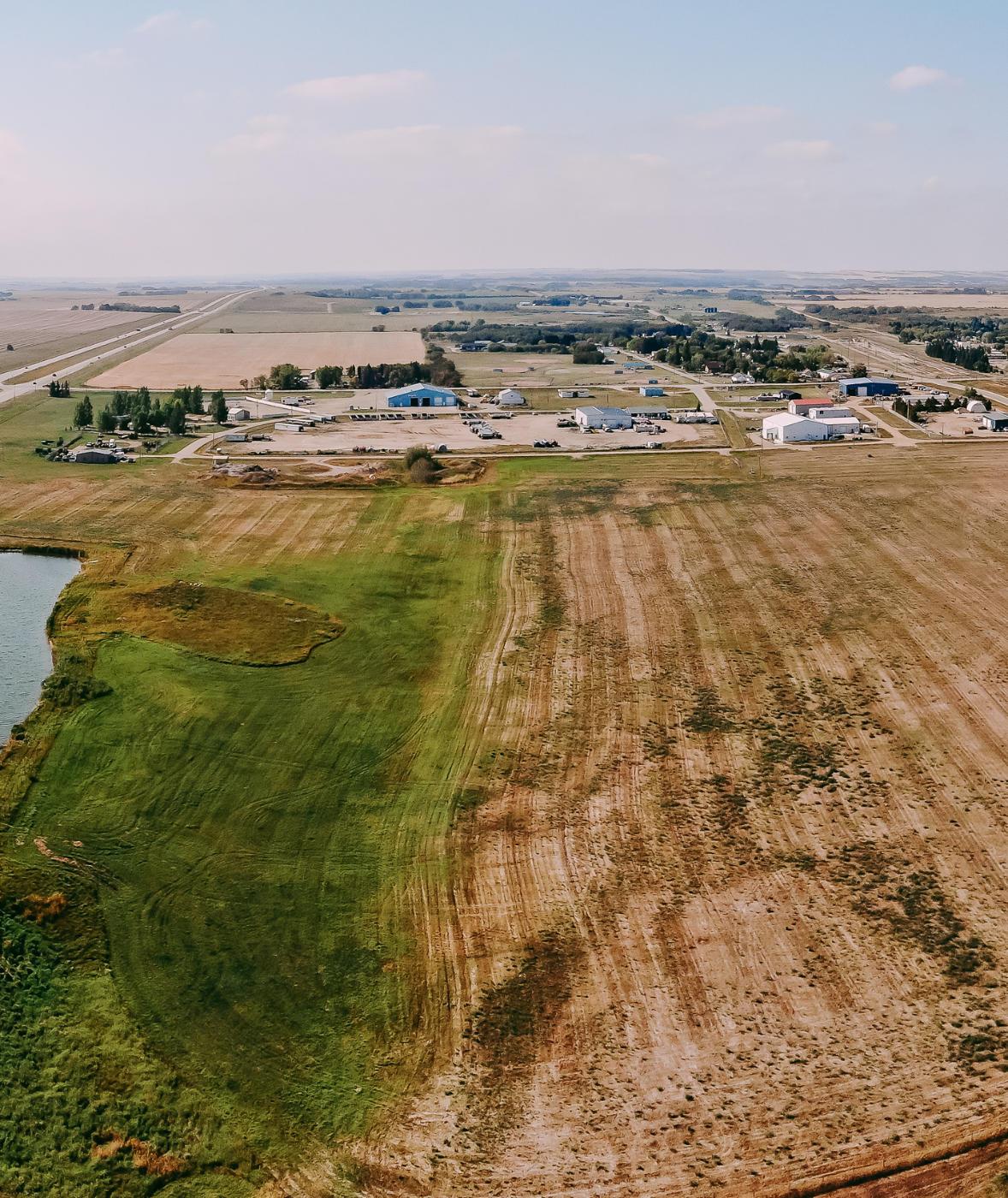
X-Terra Environmental Services Ltd. was retained to undertake a desktop biophysical assessment of the ASP lands. The following sections present the findings from X-Terra’s report, found in its entirety in Appendix A. Additionally, SolidEarth Geotechnical Inc. prepared a report (Appendix B) detailing the soils suitability for development. The findings of that report are summarized in subsection 3.1.1 below.
3.1.1 Soils&Topography
The ASP lands are within the Aspen Parkland Ecoregion and exhibit nearly level to gently rolling topography with slopes between 0.5% to 2% and low risk for erosion potential. The soils in this are consist of Orthic Black Chernozem on moderately coarse textured sediments deposited by wind or water.
SolidEarth Geotechnical undertook a field assessment in March 2023 to assess the subsurface soil and groundwater conditions at selected locations across the proposed development area (see bore hole locations on Figure 5). A drilling rig bore six holes to depths ranging from 5.8m to 7.3m below existing ground surface. The analysis concluded that soil conditions at the borehole locations are considered suitable for the proposed development, and that site grading, installation of underground utilities, construction of stormwater management ponds and pavement structures would all be feasible. Based on subsurface conditions, deep pile foundations are considered the most suitable for future structures.
7 East Industrial Park Area Structure Plan

3.1.2 Wetlands
A desktop analysis of historic aerial photographs between the years 1980 and 2021 was used to identify potential wetland areas. In total, eight graminoid marsh wetlands and one ephemeral wetland were identified, totaling 20.98 ha (see Figure 2) within the ASP boundary. Wetlands W2 and W9 extend beyond the ASP boundary, but only those portions of the wetlands within the ASP boundary are included in the total wetland area, and in Table 1 below. Future in-field surveys may find more wetlands than identified by the biophysical desktop analysis. Moreover, wetland W1 is partially formed by a humanmade borrow pit.
There are also two main drainage ditches/channels, assumed to have been created to assist with local drainage. It is unknown if Alberta Water Act approval or license was obtained for any of the human-made wetlands/watercourse features.
Any wetlands impacted by future development will require Alberta Water Act approval. Wetlands are assigned values from A to D, with D being the lowest. In terms of wetland impact mitigation and compensation, preference is to avoid impacting wetlands; however, that may not always be practical. It appears the wetlands likely to be impacted by future development are of the lowest value, D class. It is recommended that an Alberta Wetland Rapid Evaluation Tool assessment take place prior to development to determine the exact class of wetland and appropriate mitigation measures for wetland impact, including development setbacks.1
Wetland impact compensation rate for this area of Alberta is $18,600/ha in 2022, and is subject to change. The compensation values for impacting the nine identified wetlands are summarized below in Table 1 and will need to be confirmed based on future field verified wetland assessments. Future Water Act applications for direct impacts to wetlands within the ASP boundary will need to include planning, best management practices, and mitigation measures to avoid and minimize impact in order to protect those areas of wetland outside of ASP lands.
8 Existing Features | County of Minburn/Village of Mannville
1 Although the desktop analysis report does not make recommendations on development setbacks around wetlands, common practice is to employ 30-50m setbacks. This ASP assumes a 30m setback in the FLUC.
Furthermore, current values should be obtained by the developer as necessary. Wetland Compensation Summary, sourced from Table 2 in the biophysical assessment found in Appendix A of this ASP.
TABLE1— Wetland Compensation Summary
*Assumptions within table are based on historic values assigned to similar wetlands within the region. The wetlands have been delineated wetlands as per ABWRET–D directive but have not been submitted for and ABWRET Score.
**Based on desktop wetland delineations, a summary of the approximate wetland replacement for ASP lands. The values were calculated based on a replacement ratio of 1:1, relative wetland value assessment unit of 7, and an in–lieu rate of $18,600.00.
3.1.3 Vegetation
The growing season in this area is between 174 and 187 days on average. The area is primarily cultivated for agricultural purposes. There were no rare plants found during a database search although field surveys prior to development should be undertaken.
Soil disturbance during the construction of new development could attract invasive weed species and measures should be taken during construction phases to control noxious weeds.
9 East Industrial Park Area Structure Plan
Estimated WetlandValue* Approx. Wetland Area within ASP (ha) Total In–Lieu Replacement Cost** Wetland ID AWCS Classification W1 D Temporary Graminoid Marsh — M[G][II] with man–made component 6.3 $117,180.00 W2 D Seasonal Graminoid Marsh — M[G][III] 6.2 $115,320.00 W3 D Temporary Graminoid Marsh — M[G][II] 0.6 $11,160.00 W4 D Ephemeral Wetland — M[G][I] 0.03 $558.00 W5 D Temporary Graminoid Marsh — M[G][II] 0.6 $11,160.00 W6 D Temporary Graminoid Marsh — M[G][II] 0.6 $11,160.00 W7 D Temporary Graminoid Marsh — M[G][II] 0.5 $9,300.00
D Seasonal Graminoid Marsh — M[G][III] 0.05 $930.00 W9 D Seasonal Graminoid Marsh — M[G][III] 6.1 $113,460.00 20.98 $390,228.00
W8


10 Existing Features | County of Minburn/Village of Mannville HIGHWAY 881
EXISTING FEATURES: NATURAL ENVIRONMENT COUNTY OF MINBURN / VILLAGE OF MANNVILLE MANNVILLE EAST INDUSTRIAL PARK AREA STRUCTURE PLAN LEGEND IDP Boundary Plan Boundary Shadow Plan Area Village of Mannville Wetland Pond/Dugout 5 m Major/1 m Minor Contour 100 0 1:10,000 200 m 625 W
FIGURE 2
3.1.4 Wildlife
A database search revealed that no sensitive wildlife species were found within a 3km radius of the centre of the ASP area. The ASP lands are within the range of Sharptailed Grouse and Bald Eagle, however, there is potential for other sensitive species to occur in the area. Wildlife and nest sweeps should be undertaken within 7 days of the onset of development, including vegetation clearing between April 1 and August 15.
3.2 BuiltEnvironment
3.2.1 ExistingResidences
There are two existing residences within the ASP boundary, each with outbuildings and structures. See Figure 3 Existing Features: Built Environment. One residence is located north of the railway east of Range Road 85 on NW 20-50-8-W4, and the other is located south of the railway and west of Range Road 85 on NE 19-50-8-W4.
The Future Land Use Concept (Figure 5) identifies Agricultural land on which two residences exist. Over time, should landownership and development plans change, the land on which the residences are located could be identified for rural industrial development through an amendment to this ASP to change the designation from Agricultural to Industrial/Commercial.
3.2.2
Roads&Rails
The ASP is serviced by Township Road 503B, locally known as Mannville Road, Township Road 504, and Range Road 85.
Township Road 503B is a two-lane paved rural collector road with a posted speed limit of 80 km/hr. Range Road 85 is a two-lane gravel collector road with a posted speed limit of 80 km/hr. Township Road 504 is a two-lane rural collector road with a graveled surface. The posted speed limit is 80 km/hr.
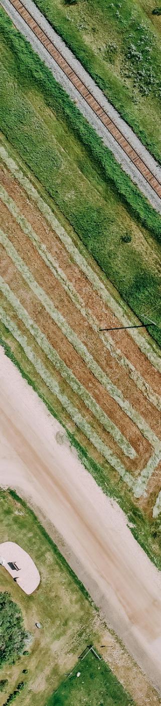
The Canadian National Railway (CN Railway) line passes diagonally from southeast to northwest through the plan area adjacent to Township Road 503A and has an uncontrolled, at-grade crossing at Range Road 85.
11 East Industrial Park Area Structure Plan

12 Existing Features | County of Minburn/Village of Mannville FIGURE 3 EXISTING FEATURES: BUILT ENVIRONMENT COUNTY OF MINBURN / VILLAGE OF MANNVILLE MANNVILLE EAST INDUSTRIAL PARK AREA STRUCTURE PLAN LEGEND IDP Boundary Plan Boundary Shadow Plan Area Village of Mannville Building/Structure Roadway Railway ACE Regional Waterline Water Main Water Well Sanitary Sewer Powerline Natural Gas Line Oil & Gas Well Fiber Optic Line 100 0 1:10,000 200 m
3.2.3 Utility&CommunicationsInfrastructure
3.2.3.1
PotableWater
The ACE Regional Waterline runs along the Township Road 504 right-of-way and partially along the north boundary of the ASP. The feasibility of connecting to this waterline needs to be determined by the developer.
3.2.3.2
VillageofMannvilleLagoon
The Village of Mannville’s sewage lagoon is permitted to discharge treated effluent from the lagoon’s storage cells into the Vermilion River once per year during a three-week period between March 1st and November 30th (BAR Engineering, 2009).
In response to the Village experiencing difficulty being able to retain the volume of treated effluent within its storage cells to allow for the annual discharge at the same time every year, BAR Engineering was retained in 2009 to undertake an analysis of the lagoon capacity (BAR Engineering, 2009).
The 2009 analysis concluded that existing anerobic cells of the lagoon are adequately sized to meet the current and future needs of the Village. However, the storage cells of the lagoon could be challenged to provide adequate storage capacity to accommodate any population growth or unanticipated additional flows caused by inflow and infiltration during a wet, rainy year or major storm event (BAR Engineering, 2009). These circumstances could require a premature discharge of the effluent from the storage cells to avoid the storage berms from being over-topped (BAR Engineering, 2009).
3.2.3.3
Power
A power line runs along the Range Road 85 right-of-way from south of Highway 16 and veers west along Township Road 503A into the Village of Mannville. It branches south to service the lands adjacent to the Shadow Plan area within the Village of Mannville.
3.2.3.4
Communications
The MCSNet fiber optic line runs along the north side of Highway 16 and enters the Village of Mannville along Highway 881. The line runs through the Village’s existing industrial park just west of the ASP boundary and ties back into the Highway 16 alignment. The line can be extended into the East Mannville Industrial Park from a point just outside the very southwest corner of the plan as well as from a point at Range Road 85 where it intersects with Highway 16.
13 East Industrial Park Area Structure Plan

14 Existing Features | County of Minburn/Village of Mannville FIGURE 4 EXISTING FEATURES: LAND USE COUNTY OF MINBURN / VILLAGE OF MANNVILLE MANNVILLE EAST INDUSTRIAL PARK AREA STRUCTURE PLAN LEGEND IDP Boundary Plan Boundary Shadow Plan Area County –A: Agricultural County –DC: Direct Control County –RC: Rural Commercial Environmental Reserve Village –P1: Public Service Village –R1: Residential Low Density Single Dwelling Village –UH: Urban Holding Village –IB1: Industrial Business Park 100 0 1:10,000 200 m

3.2.4 Oil&GasInfrastructure
There are no oil and gas wells within the ASP boundary. There are natural gas pipelines servicing the two residences in the plan area. A natural gas pipeline is also located in the Shadow Plan area.
3.2.5 ExistingLandUse
The land use districts applied to the land within the ASP include Agricultural District, Direct Control District, and Rural Commercial District as shown on Figure 4. The majority of the land is districted (or zoned) Agricultural. Approximately 32 ha are districted Direct Control and a single 4 ha parcel was previously redistricted from Agricultural to Rural Commercial in anticipation of a development that did not occur.
Lands within the Shadow Plan area in the Village are districted Industrial Business Park.
3.2.6 CulturalandHistoricalResources
A search of the Alberta Listing of Historic Resources July 2022 did not identify any historic resources value and therefore a Historical Resources Act clearance will not be required to support future development.
15 East Industrial Park Area Structure Plan
⁹.¹⁰.¹

4.0 Future Land Use Concept
The Future Land Use Concept, depicted in Figure 5, proposes a rural industrial park development with hybrid servicing options, as detailed in the following sections.
4.1 FutureLandUseConcept
The Future Land Use Concept (FLUC) comprises agricultural lands and land identified for future rural commercial/industrial, with independently serviced lots (eastern half of ASP boundary) and potentially municipally serviced lots (western half of ASP boundary). The road layout is simple and designed to minimize additional development costs. The subdivision layout shown is conceptual and for discussion purposes only. Changes to the subdivision concept shown will not require an amendment to the ASP.
The total ASP area is approximately 120 ha, of which approximately 47 ha is identified for future rural industrial development and 13 ha is dedicated for road rights-of-way (see Table 2 below).
16 Future Land Use Concept | County of Minburn/Village of Mannville
TABLE2— Land Use Statistics
The Shadow Plan area within the Village of Mannville is identified with grey hatching and comprises 3.22 ha of land. The Shadow Plan area highlights continuity of land uses and future roadway connections to meet the market needs for smaller, fully serviced industrial lots. There are two roadway connection points from the Shadow Plan area to the ASP lands, one at the north and one at the south.
Existing wetlands represent approximately 21 ha of land, and setbacks around these wetlands may be dedicated as environmental reserve or environmental reserve easement. Setbacks will need to be determined by a qualified professional prior to subdivision based on future field verified wetland assessment.
It is important to the Village’s economic development that its supply of existing industrial land be mostly built out before the smaller lots identified in the western half of the ASP boundary are subdivided, serviced and marketed.
17 West Industrial Park Area Structure Plan
Area (ha) Area (ac) % Of GDA Land Use Type PLAN AREA hectares acres % of GDA Gross Developable Area (GDA) 120.01 296.5 100.0% Agricultural 53.59 132.4 44.65% Industrial 47.13 116.5 39.27% Road 13.04 32.2 10.87% Rail 6.25 15.4 5.21% SHADOW PLAN hectares acres % of GDA Gross Developable Area (GDA) 3.55 8.8 100.0% Industrial 3.22 8.0 90.70% Road 0.33 0.8 9.30% TOTAL hectares acres % of GDA Gross Developable Area (GDA) 123.56 305.3 100.0% Agricultural 53.59 132.4 43.37% Industrial 50.35 124.4 40.75% Road 13.37 33.0 10.82% Rail 6.25 15.4 5.06%


18 Future Land Use Concept 0.97ha 2.40ac 0.68ha 1.68ac 0.41ha 1.00ac 0.41ha 1.00ac 0.58ha 1.44ac 0.42ha 1.05ac 0.41ha 1.01ac 0.41ha 1.01ac 0.41ha 1.01ac 0.81ha 2.00ac 1.29ha 3.18ac 1.21ha 3.00ac 1.21ha 3.00ac 0.41ha 1.00ac 0.41ha 1.00ac 0.43ha 1.06ac 2.42ha 5.99ac 2.43ha 6.01ac 2.83ha 6.99ac 2.83ha 6.99ac 2.83ha 6.99ac 2.84ha 7.01ac 3.76ha 9.29ac 3.25ha 8.03ac 3.24ha 8.00ac 3.22ha 7.96ac 4.03ha 9.97ac 2.98ha 7.35ac 140.68 297.97 118.68 21.12 282.99 270.03 29.98 68.61 165.60 12.73 149.32 70.28 44.3734.33 205.03 152.81 132.37 118.57 256.77 232.22 204.81 173.16 155.51 149.50 129.50 116.00 21.40 160.14 172.57 195.60 259.00 96.69 274.98 200.56 175.81 178.87 216.30 201.01 178.65 152.96 142.83 172.11 150.24 15.11 149.85 137.64 262.70 9.96 W2 W3 W4 W5 W7 W8 W9 W6 W1 23-6 23-1 23-2 23-5 23-4 23-3
5 FUTURE LAND USE CONCEPT COUNTY OF MINBURN / VILLAGE OF MANNVILLE MANNVILLE EAST INDUSTRIAL PARK AREA STRUCTURE PLAN LEGEND IDP Boundary Plan Boundary Shadow Plan Area Village of Mannville Industrial/Commercial Agricultural
100 0 1:10,000 200 m 23-1
FIGURE
Borehole Location (with ID)
Two residences exist within the ASP boundary as discussed in 3.2.1. above. The land on which these residences sit may be converted to the Industrial or Rural Commercial designations in the future, but that would require an amendment to this ASP.
4.2 Industrial/Commercial
The intent of this ASP is to support the future conversion of agricultural land within the ASP boundary designated Industrial/Commercial for either rural industrial or appropriate rural commercial uses. This could include light industrial uses that are more commercial in nature, and which could benefit from smaller parcels that have access to full municipal servicing, as well as those rural industrial uses that are a bit more intensive and require larger tracts of unserviced land. That being said, Agricultural uses can continue as they currently do in perpetuity if that is the will of the landowners.
It is expected that rural industrial types of uses on larger parcels are best suited for development within the County. Uses that require smaller, serviced lots would be directed to the Village’s existing serviced industrial lots in the first instance. Access to the smaller, potentially serviced lots shown in Figure 5 would be promoted after the Village’s existing supply of small-lot serviced industrial lots are mostly developed. Should demand for smaller, serviced lots not arise within the County’s ASP, the smaller lots shown in Figure 5 could be reconfigured as larger parcels with independent servicing. A reimagining of the lot layout and servicing methods for the smaller lots within the ASP boundary could require an amendment to this ASP as the changes could impact overall stormwater management. Additional engineering analysis of the impacts of reconfiguring the smaller lots on stormwater management should accompany an amendment application.
Careful consideration of the siting and screening of future industrial development is required in consideration of the existing residential uses within the Agricultural land use district. Uses suitable for adjacency to the existing residences should not produce excessive light trespass, noise, dust, smells or other nuisance that is in excess of what one might experience living next to an agricultural operation. Such uses should be directed away from the existing residences.
Additionally, screening and fencing should be employed to reduce negative visual impact of laydown yards, outdoor storage of equipment and other uses with potential for unsightliness where proposed to be located adjacent to the existing residences or within sightlines of Highway 16.
19 West Industrial Park Area Structure Plan
CN Rail sets out guidelines for development in proximity to rail lines. It is expected that developers will avail themselves of these guidelines and development proposals will reflect the design parameters contained therein.
4.3 Agricultural
Agriculture is the current dominant use within the ASP boundary. This ASP upholds the right to farm for existing and legally permitted agricultural operations. Agricultural landowners can continue to use their agricultural properties in the ways they currently do in perpetuity, in compliance with the County’s land use bylaw and applicable policies.
On the other hand, should the owners of the existing residences desire to sell or develop their land for industrial uses, the conversion from Agriculture designation to Industrial designation is generally supported by this ASP. However, an amendment to this ASP would be required, and may warrant further engineering analysis depending on the extend of the amendment.
4.4 SequenceofDevelopment
The anticipated sequence of development is shown in Figure 6. It should be noted that the timeframe for full build out of this area is likely decades, and many factors that are unknown at this time could influence the sequence of development.
However, it is expected that the larger, unserviced lots within eastern half of the ASP boundary with visibility from Highway 16 will develop first. The next group of unserviced lots to develop will likely be those north of the CN Railway, west of Range Road 85. Finally, those smaller, potentially serviced lots in the western half of the ASP boundary adjacent to the Village’s east boundary will likely develop last in consideration of the County’s commitment to avoiding direct competition with the Village for serviced industrial lots.
Changes in the sequence of development may require an amendment to this ASP depending on their impact on servicing, stormwater management and other factors determined by the Development Authority.
20 Future Land Use Concept
4.5 ReserveLands
The MGA enables municipalities to obtain land through the subdivision process for reserves: municipal, school, municipal and school, and environmental. The MGA also enables certain lands to be dedicated as environmental reserve easements and conservation easements.
It is the policy of this ASP that reserve dedication be maximized pursuant to the MGA. Also, municipal reserve dedication may be provided in the form of cash in lieu of land as local park space is not the best use of reserves in this area of the county. It is recommended that the County not accept municipal reserve deferral considering the timeframe for full build-out of this land could be decades, possibly deferring provision of municipal reserve, and the broader community benefits it could provide, indefinitely.
It is expected that further in-field analysis by a qualified professional in support of future subdivision and development will determine appropriate development setbacks to retained wetlands. The setbacks around wetlands, as well as the retained wetlands themselves, can be identified as environmental reserve at the time of subdivision.
Stormwater management (SWM) ponds will not be identified as environmental reserve. Further, the land around SWM ponds that is above the high-water mark cannot be used as credit for municipal reserve dedication. Finally, SWM ponds should not be identified as public utility lots through subdivision on private land because the County should not take on responsibility of maintenance for private stormwater management ponds. Rather, the County should encourage owners to naturalize private stormwater management ponds to reduce maintenance requirements and to dissuade human access.
21 East Industrial Park Area Structure Plan
22 Future Land Use Concept | County of Minburn/Village of Mannville 4 1 3 2 6 5 FIGURE 6 SEQUENCE OF DEVELOPMENT COUNTY OF MINBURN / VILLAGE OF MANNVILLE MANNVILLE EAST INDUSTRIAL PARK AREA STRUCTURE PLAN LEGEND IDP Boundary Plan Boundary Shadow Plan Area Village of Mannville Development Phasing 100 0 1:10,000 200 m 3
5.0 Transportation Network
Bunt & Associates Engineering was retained to undertake a desktop transportation review (see Appendix D). BAR Engineering was retained to prepare a Servicing Brief (Appendix E). The recommendations of these two reports are presented below.
5.1 LocalRoads
All proposed roadways within the ASP will be developed to a rural cross section to the County’s most up-to-date required standards, with roadside ditches to provide drainage and convey stormwater runoff. In any case, roadways should be constructed to accommodate a minimum 9m finished top width to support truck traffic.
5.2 AccessManagement
Access management is important in maintaining acceptable levels of service and safety on roadways. It is recommended that intersection spacing on Range Road 85 is 60m, this includes spacing from the intersection of Range Road 85 and the CN Railway. In other words, from the intersection of Range Road 85 and the CN Railway in either direction, the next closest intersection should be no closer than 60m.

23 East Industrial Park Area Structure Plan
With the anticipated future interchange, the east-west collector roads may see greater traffic volumes and therefore intersection spacing along Mannville Road (Township Roads 503B) and 504 is recommended to be 100m.
5.3 Off-SiteImprovements
Development pressures within the western half of the ASP boundary may necessitate off-site improvements to the transportation network within the Village. In particular, the intersection of 48 Avenue (Township Road 503B/Mannville Road) and 45 Street may need enhancement. Necessary improvements will be determined through the preparation of a Transportation Impact Assessment at the time of subdivision or development, and all costs associated with transportation network improvements in support of proposed development will be the responsibility of the developer.
5.4 Highway16/881
Interchange
Highway 16 is classified as a rural freeway divided highway within Alberta Transportation’s roadway hierarchy. Highway 16’s freeway status requires the closure of at-grade intersections and development of interchanges at key locations.
Alberta Transportation’s Highway 16 access management plan identifies the closure of the at-grade intersection of Highway 16 and Range Road 85 (and Range Road 84 east of the ASP boundary). It also identifies the location of an interchange at the intersection of Highway 16 and Highway 881 (see Figure 7). After at-grade intersections are closed and the interchange is constructed, access to the ASP area from Highway 16 will be through the Village of Mannville via Highway 881 and Township Roads 503B and 504.
24 Transportation Network | County of Minburn/Village of Mannville
The construction of the interchange will also impact existing developed properties and roadways within the Village’s existing industrial park. As shown in Figure 7, roadways from within the Village’s industrial park are proposed to extend eastward into the ASP lands. The southernmost road extension may be impacted by the footprint of the proposed interchange. The ASP internal roadway design anticipates this possibility and maintains public road access to all parcels post-interchange construction.
5.5 CNRailway
The existing access spacing along Range Road 85 relative to the CN Railway and Township Road 503B may not meet the minimum 60m spacing recommended by Bunt & Associates, although it may meet the Government of Canada’s Grade Crossing Standard of a minimum 30m from the edge of the travelled way to the nearest rail of the grade crossing. The spacing will impact the stacking distance for larger vehicles, like a WB-21 semi-trailer or a WB-23 double trailer. If stacking distance becomes a safety issue over time, Township Road 503B may need to be realigned south of its current Range Road 85 intersection location.
The existing CN Railway crossing controls in and adjacent to the ASP may also need to be upgraded over time as traffic volumes increase to maintain safety.
5.6 AdditionalAnalyses
The desktop review undertaken for this ASP does not provide sufficient level of analysis to support subdivision and development. The developer may be required to undertake a traffic impact assessment (TIA) in support of subdivision to determine if intersection upgrades or controls are required because of development.
In addition to a TIA, a geotechnical investigation for roadway construction to confirm soil stratigraphy, suitability of existing soil for construction, and to recommend road pavement structures based on soils and vehicular loading.
25 West Industrial Park Area Structure Plan
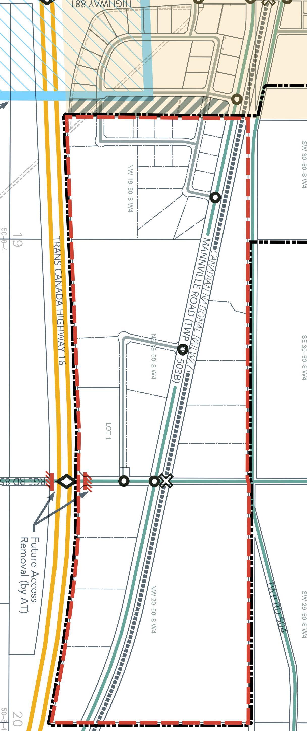
26 Transportation Network FIGURE 7 TRANSPORTATION NETWORK COUNTY OF MINBURN / VILLAGE OF MANNVILLE MANNVILLE EAST INDUSTRIAL PARK AREA STRUCTURE PLAN LEGEND IDP Boundary Plan Boundary Shadow Plan Area Village of Mannville Canadian National Railway Highway Collector/Rural Roadway Local Roadway Major Intersection Minor Intersection CNR Crossing Future Access Removal 100 0 1:10,000 200 m
6.0 Servicing
BAR Engineering prepared a Servicing Brief (Appendix E) and a Stormwater Management Plan (Appendix F) to provide high level engineering review, analysis and recommendations for the ASP lands. The discussions below are derived from and informed by this document.
6.1 Water
The lands within the ASP boundary are not currently serviced with a municipal water distribution system. If a municipal water distribution system were to be extended into the ASP area, it would extend from the Shadow Plan area. All costs associated with accessing the ACE waterline and obtaining necessary utility right-of-way would be the responsibility of the developer.
The Village of Mannville is supplied with water from the ACE Waterline Corporation. A watermain, owned and operated by the County, would be required from the connection points at 47A Avenue/45 Street and 45 Street and looped throughout the development to provide service (see Figure 8).
Although a municipal water distribution system within the ASP is contemplated, it would not be considered until most of the serviced industrial lots within the Village of Mannville have built out to avoid creating competition for serviced industrial land that could be detrimental to the economic well-being of the Village. It is anticipated that rural water servicing consisting of individual water wells or cisterns will be used in the interim.

27 East Industrial Park Area Structure Plan
Water well servicing will require supporting groundwater/ hydrogeological assessments prior to and as part of the subdivision process and will require approval and authorization from the Alberta Environment and Protected Areas to use groundwater.
6.2 Wastewater
The ASP lands are not serviced by a municipal wastewater system. However, services could be extended from the Shadow Plan area to the western lots of the ASP boundary (Figure 8). Sanitary sewage for the Village is treated at the Village lagoon.
6.2.1 ServicingFeasibility
A municipal wastewater collection system for the ASP lands could consist of a low-pressure collection system and/or gravity sanitary mains in combination with lift stations. The costeffectiveness of such a system needs further analysis and is outside the scope of this ASP.
However, with the possible capacity challenges of the Village’s lagoon storage cells discussed above, and the possible need for one or more lift stations to support sanitary servicing in the ASP boundary, a municipal wastewater system to service the ASP lands could be cost-prohibitive. If this proved to be the case, then the smaller lots shown in Figure 8 in the western half of the ASP may not be large enough to support independent servicing, such as septic tanks and treatment fields/mounds, and would instead be required to be serviced with holding tanks in order to meet provincial setback requirements.
Municipal servicing feasibility within the ASP boundary requires additional discussion between the Village of Mannville and the County of Minburn.
28 Servicing | County of Minburn/Village of Mannville
6.2.2 VillageLagoonCapacity
To inform consideration of urban service provision to the smaller industrial lots within the western half of ASP boundary, BAR Engineering (BAR) was retained to update its 2009 capacity analysis of the Village’s lagoon. A summary is provided below, and the detailed analysis can be found in Appendix C.
In summary, the 2023 report confirms the 2009 report findings, and identifies that providing servicing for development outside of the Village’s boundary will require lagoon capacity upgrades. While a lagoon upgrade is contemplated by the Village in the future, the timing of such a project would be subject to the Village’s capital budgeting prioritization process.
6.3 StormwaterManagement
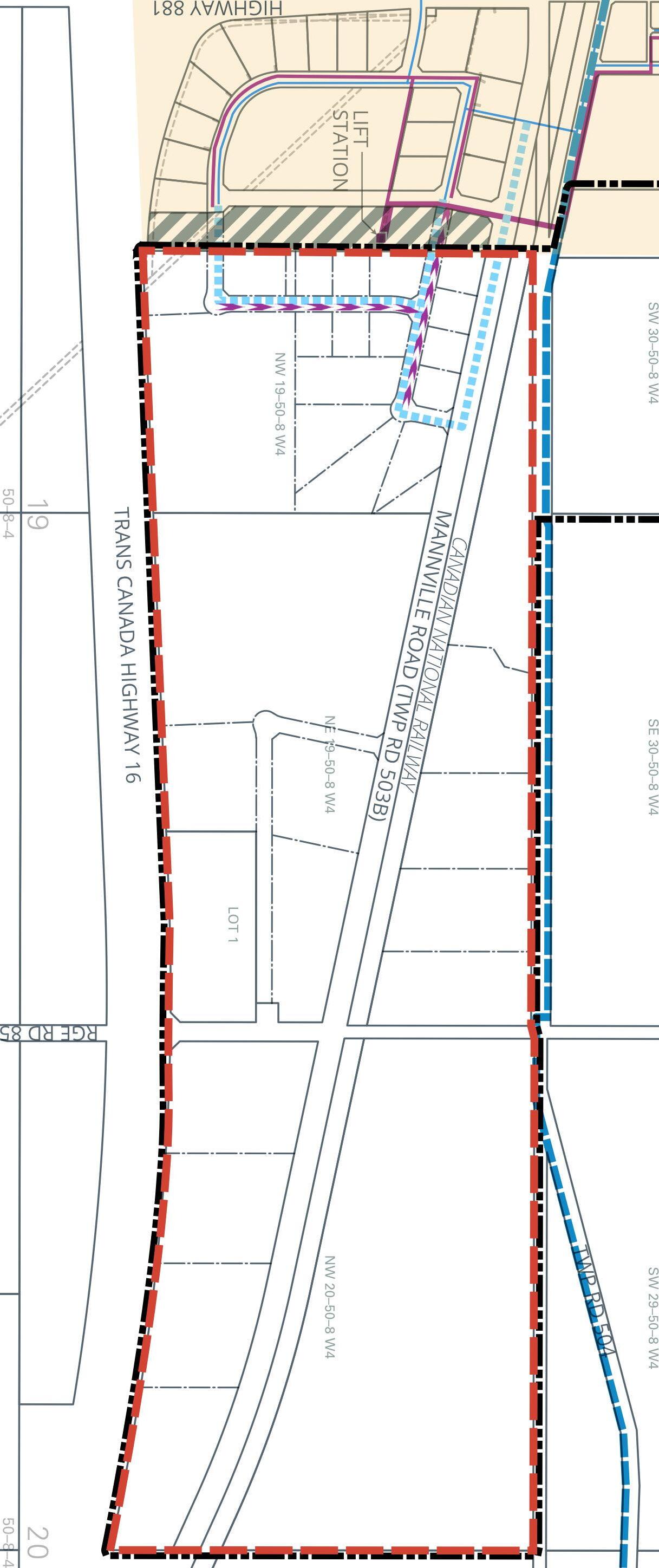
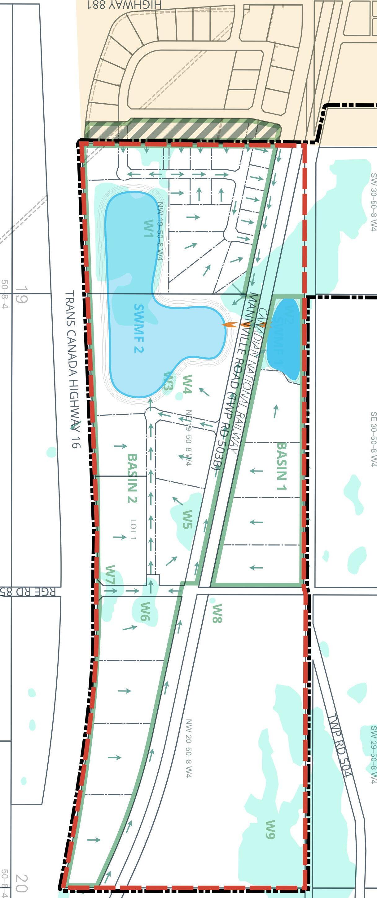
Two stormwater management scenarios in the Stormwater Management Plan (Appendix F) were developed and analyzed to support maximum flexibility of development in the future. The two stormwater management concepts are illustrated conceptually in Figures 9A and 9B.
Both scenarios assumed wetponds (stormwater management ponds) would be used to provide water quality enhancement through settling of runoff pollutants within the permanent pool, or the normal water levels. Rain event runoff is assumed to be stored above the permanent pool and released downstream at a restricted rate after the rain fall event has ended. The rate of release is generally kept at the same rate as at pre-development to mitigate impacts on downstream watercourse. The storage area of the wetpond is within 2m above the permanent pool and can store 1 in 100-year storm runoff or the 1 in 25-year storm runoff for a period of 24 hours. Additional design assumptions and details can be found in Appendix F
Scenario 1 (Figure 9A) includes an overall stormwater management system consisting of interconnected stormwater management ponds for all the proposed development areas.
Scenario 2 (Figure 9B) consists of a dedicated stormwater management pond for the smaller, potentially serviced lots adjacent to the Village coupled with private on-site stormwater management storage ponds on the remaining parcels.
29 East Industrial Park Area Structure Plan
30 Servicing | County of Minburn/Village of Mannville FIGURE 8 SERVICING COUNTY OF MINBURN / VILLAGE OF MANNVILLE MANNVILLE EAST INDUSTRIAL PARK AREA STRUCTURE PLAN LEGEND IDP Boundary Plan Boundary Shadow Plan Area Village of Mannville ACE Regional Waterline Existing Water Main 100 0 1:10,000 200 m Proposed Water Main Existing Sanitary Sewer Proposed Sanitary Sewer
Further review and refinement of the stormwater management plan will be required at the subdivision stage once phasing has been confirmed as phasing may impact the proposed stormwater management pond locations.
The minimum setback required by Alberta Transportation for stormwater management ponds is 40m from the edge of the road right-of-way. This setback distance may be reduced by Alberta Transportation to 30 m if the pond is protected by a berm and/or fence and/or guard rail. The current dugout/stormwater pond has a setback distance of 30 m. Any new stormwater management facilities should be installed no closer to Highway 16 than the current dugout/stormwater pond. Additionally, the developer will require a roadside development permit from Alberta Transportation for construction of all stormwater management ponds and infrastructure within 800m of the centerline of Highway 16 prior to development.
6.4 ShallowUtilities
Shallow utilities will be brought into sites as needed by the developers, and rights-of-way will be established at the time of subdivision as needed. Specifically, ATCO Gas requires that a suitable alignment be provided within the boulevards of all arterial and major roads for the ATCO Gas feeder mains.
31 West Industrial Park Area Structure Plan
32 Servicing FIGURE 9A STORM WATER: SCENARIO 1 COUNTY OF MINBURN / VILLAGE OF MANNVILLE MANNVILLE EAST INDUSTRIAL PARK AREA STRUCTURE PLAN LEGEND IDP Boundary Plan Boundary Shadow Plan
Village of
Wetland Storm
100 0 1:10,000 200 m General Drainage
Area
Mannville
Pond
Direction Proposed Storm Sewer Catchment Boundary
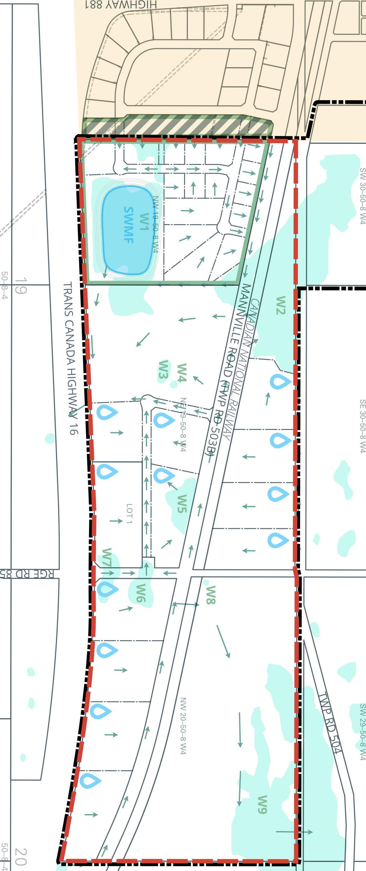
33 East Industrial Park Area Structure Plan FIGURE 9B STORM WATER: SCENARIO 2 COUNTY OF MINBURN / VILLAGE OF MANNVILLE MANNVILLE EAST INDUSTRIAL PARK AREA STRUCTURE PLAN LEGEND IDP Boundary Plan Boundary Shadow Plan Area Village of Mannville Wetland Storm Pond 100 0 1:10,000 200 m General Drainage Direction Catchment Boundary Private On–Site Storm Water Management Requried 9.11
7.0 Earthworks
The field analysis undertaken by SolidEarth Geotechnical led to numerous findings and recommendations for development in its report, found in Appendix B. It should be noted that the recommendations are preliminary only and should not be used in detailed design. A detailed geotechnical investigation should be completed for each proposed development lot/ building site during the detailed design stage.
Findings and recommendations were developed for site development, foundation options and preliminary design, stormwater management pond, installation of buried utilities, and pavement structure.
The recommendations for site development are summarized below. For details and full discussion of the other key areas of analysis, please reference the source document.
Subgrade Preparation
1. During initial site grading, all topsoil should be stripped and removed from the site.
2. Topsoil should not be mixed with mineral soils or be used as engineered fill material.
34 Earthworks | County of Minburn/Village of Mannville
3. Construction traffic on unprotected subgrade should be kept to a minimum and restricted to low pressure track equipment to the extent possible
a. Exposed subgrade may be sensitive to heavy rubber-tire construction equipment, especially in wet conditions,
b. Soft subgrade conditions may be encountered at some locations, particularly following snow melt and heavy rain events.
4. All exposed subgrade, following achievement of rough grades, should be inspected by a geotechnical engineer, and include a proof-roll test to confirm that deflections from construction traffic are minimal. Soft and weak areas identified during inspection should be strengthened and improved.
5. Engineered fill should consist of low to medium plastic clay or a wellgraded, granular material.
6. All fill soils should be free from any organic materials, contamination, deleterious construction debris, and stone greater than 150mm in diameter.
Requirement for Engineered Fill
1. Engineered fill should be thawed when placed and placed during nonfrozen conditions.
2. All engineered fill should be compacted to a minimum of 98% of standard Proctor maximum dry density (SPMDD) within the proposed building envelopes, and to a minimum 95% of SPMDD within graveled yards and paved areas.
3. The upper 300mm of the subgrade within the paved areas should be compacted to 98% of SPMDD.
4. Fill should be compacted in lift thickness of 300mm (loose) or less, and within two percent of the optimum moisture content of the soil.
35 East Industrial Park Area Structure Plan
5. Engineered fill within the building footprint should extend at least 1.5m, or the thickness of the fill, beyond the footprint of the building.
6. Fill placement procedures and quality of the fill oils should be monitored by geotechnical personnel.
7. Field monitoring should include compaction testing at regular frequencies.
8. Settlement in the order of one to three percent of the fill thickness should be anticipated for engineered fill compacted between 98% and 95% SPMDD. The majority of this settlement is expected to occur within the first year following construction.
Site Drainage
1. A minimum grade of 2% is recommended at the subgrade level to accommodate surface water runoff away from the development area.
2. The upper 300mm of the backfill around buildings (where no pavement structure is proposed) should consist of compacted clay to act as a seal against runoff water. The clay should extend a minimum distance of 3m away from the building and should be graded at a slope of 5% or more.
3. Positive surface drainage should be provided in the early stages of construction to prevent ponding of water and softening of the subgrade.
36 Earthworks | County of Minburn/Village of Mannville
8.0 Interpretation & Implementation
8.1 Interpretation
Policies are written using “shall”, “should” or “may” statements. The interpretations of “shall”, “should” and “may” that follow provide the reader with a greater understanding of the intent of each policy statement:
‘Shall’ — denotes compliance or adherence to a preferred course of action.
‘Should’ — denotes compliance is desired or advised but may be impractical or premature because of valid planning principles or unique/ extenuating circumstances.
‘May’ — denotes discretionary compliance or a choice in applying policy.

37 East Industrial Park Area Structure Plan
8.2 Monitoring&Amendment
Plan implementation will be primarily through the subdivision and development of land in ways consistent with the policies and vision of this ASP. Variances to the requirements of this ASP should not be considered unless supported by defensible planning rationale. Part of implementation is monitoring the document for continued consistency with the County’s plans and policies, as well as higher-order statutory documents. This ASP should be reviewed at least every five years to ensure its continued relevance.
Occasionally, it will be desired or necessary to amend the ASP to keep it consistent with changing policies, market needs, or to address housekeeping matters. Housekeeping amendments consisting of correcting typos, grammatical errors and the like will not necessitate a formal amendment process. However, major amendments, such as changing land use designations, locations of major infrastructure or other similarly substantive changes, will trigger a formal amendment process including notification, public engagement and circulation to agencies pursuant to the MGA.
38 Interpretation & Implementation | County of Minburn/Village of Mannville
9.0 Policies
9.1 General
Development Control
POLICY 1
The developer shall be required to seek a Roadside Development Permit from Alberta Transportation for all development proposals.
Compliance with ASP
POLICY 2
POLICY 3
The County of Minburn shall ensure that all future land use, subdivision and development, and amendment decisions made with respect to lands within the boundary of the Mannville East Industrial Park ASP comply with the provisions contained within this ASP, including the Figures. Decisions related to document ‘housekeeping’ or those that would be considered minor deviations, relaxations, or variations from the provisions of this ASP would not require an amendment to this document where it can be demonstrated that the deviation, relaxation or variance does not substantively alter the intent, force or effect of the provisions of this ASP.
The developer shall ensure that all site preparation, public road, and any other public facility/improvement is professionally engineered and constructed to the satisfaction of the County of Minburn in accordance with the County’s standards.
39 East Industrial Park Area Structure Plan
9.2 Environment
POLICY 4
POLICY 5
POLICY 6
POLICY 7
POLICY 8
POLICY 9
Developers shall undertake an Alberta Wetland Rapid Evaluation Tool assessment prior to development, and in support of subdivision, to determine the exact class of wetland and appropriate mitigation measures for wetland impact, including development setbacks, contained within development area or plan of subdivision.
The developer shall require Alberta Water Act approval prior to impacting existing wetlands.
The developer shall employ measures during construction to control noxious weeds.
The developer shall develop and employ a sedimentation and erosion control plan, especially around retained wetlands.
The developer should undertake a field survey prior to development to determine the presence of rare plant species.
The developer should undertake wildlife and nest sweeps between April 1 and August 15 and within seven (7) days of the onset of development, including vegetation clearing.
9.3 Industrial
POLICY 10
POLICY 11
POLICY 12
The County shall ensure that Industrial uses proposed to be located immediately adjacent existing residences should not produce excessive light trespass, noise, dust, smells or other nuisance that is, in the opinion of the Development Authority, in excess of what one might experience living next to an agricultural operation.
The County shall require screening and/or fencing to be employed to reduce negative visual impact of laydown yards, outdoor storage of equipment and other uses with potential for unsightliness in proximity to existing residences.
Developers shall avail themselves of the CN Rail Proximity Guidelines and development proposals shall be respectful of and reflect the suggested design parameters contained therein.
40 Policies | County of Minburn/Village of Mannville
9.4 Agricultural
POLICY 13 The County shall allow existing agricultural operations to continue in perpetuity at the will of the landowner.
POLICY 14
POLICY 15
POLICY 16
The County should ensure that existing agricultural operations in the Agricultural designation are not unduly impeded and/or impacted upon by future adjacent non-agricultural development within the ASP boundary.
The County shall allow the existing residences within the Agricultural designation to remain or to be renovated or reconstructed in compliance with all applicable bylaws and building codes.
The County shall not support new residential developments within the ASP boundary.
POLICY 17 The County should support conversion of Agricultural designated land to Industrial/Commercial designation with an amendment application supported by additional analysis proving suitability of the land for the intended use.
9.5 SequenceofDevelopment
POLICY 18 The County should ensure the development of the smaller, potentially serviced lots within the western half of the ASP boundary occurs after the Village of Manville’s supply of existing industrial land within the Shadow Plan area is mostly built out.
9.6 ReserveLands
POLICY 19 The County shall maximize reserve dedication pursuant to the MGA.
POLICY 20 The County should allow for municipal reserve dedication in the form of cash in lieu of land.
POLICY 21 The County should not permit municipal reserve deferral.
41 East Industrial Park Area Structure Plan
POLICY 22
POLICY 23
POLICY 24
The County shall dedicate the setbacks around wetlands, as well as the retained wetlands themselves, as environmental reserve or environmental reserve easement at the time of subdivision.
The County shall not identify naturalized or converted wetland stormwater management ponds as environmental reserve.
The County shall not give municipal reserve credit for land above the highwater mark of stormwater management ponds.
9.7 Transportation
Roads & Access
POLICY 25
POLICY 26
POLICY 27
POLICY 28
POLICY 29
The County shall require that all proposed roadways within the ASP are engineered, designed, and developed to a rural cross section with roadside ditches to provide drainage and convey stormwater runoff, to the County’s current road standards.
The County should require that roadways are constructed to accommodate a minimum 9m finished top width to support truck traffic.
The County should require intersection spacing on Range Road 85 is a minimum 60m.
The County should require intersection spacing on Township Roads 503B and 504 is a minimum 100m.
The County shall ensure that a suitable alignment is provided within the boulevards of all arterial and major roads for the ATCO Gas feeder mains.
Traffic Impact Assessment
POLICY 30 The developer may be required to prepare a Traffic Impact Assessment (TIA), at their sole expense, in support of a subdivision or development permit application. The scope of the TIA will be determined by Alberta Transportation and the County of Minburn. If a TIA should be required, it will be prepared to the satisfaction of Alberta Transportation, in consultation with the County.
42 Policies | County of Minburn/Village of Mannville
POLICY 31 The developer shall undertake a Traffic Impact Assessment to determine if the at-grade intersection of Hwy 16 & RR85 will need improvements to make sure that the intersection will be able to safely accommodate the traffic generated by the development.
On– and Off–Site Improvements
POLICY 32 The developer shall undertake, at the sole cost of the developer, any engineering, requirements or improvements identified in or resulting from the TIA approved by the County and/or Alberta Transportation, or any other engineering, requirement or improvement specified by Alberta Transportation in relation to Highway 16 or Highway 881 as a result of or that is attributable to the development of land within this ASP must be undertaken to the satisfaction of Alberta Transportation, in consultation with the County.
POLICY 33 The developer shall be responsible for all costs associated with transportation network improvements in support proposed development as identified in an approved Traffic Impact Assessment.
CN Railway
POLICY 34
The County may need to consider realigning Township Road 503B south of its current Range Road 85 intersection location if stacking distance between the CN Railway and Township Road 503B becomes a safety issue.
POLICY 35 The County may need to collaborate with CN Railway to improve crossing controls in and adjacent to the ASP over time as traffic volumes increase, in order to maintain safety.
Additional Analyses
POLICY 36 The developer shall undertake a geotechnical investigation to confirm soil stratigraphy, suitability of existing soil for construction, and to recommend road pavement structures based on soils and vehicular loading.
43 East Industrial Park Area Structure Plan
9.8
Services
General
POLICY 37
The County shall require that the smaller lots adjacent to the Village’s eastern boundary, as depicted conceptually in Figure 5, be serviced by municipal services if those services are available at the time of development. All costs associated with connecting to municipal services shall be borne by the developer.
Water
POLICY 38 Water well servicing will require supporting groundwater/hydrogeological assessments prior to and as part of the subdivision process and will require approval and authorization from Alberta Environment and Protected Areas to use groundwater.
POLICY 39 The Developer shall bear all costs associated with accessing and distributing potable water from the ACE water line in support of their development.
Wastewater
POLICY 40
The County shall require sanitary sewer holding tanks on lots 2.02ha in area or smaller to ensure provincial setback requirements are met.
POLICY 41 The County shall discuss municipal sanitary sewer servicing options within the ASP boundary with the Village of Mannville.
Stormwater Management
POLICY 42
POLICY 43
The County shall not identify private stormwater management ponds as public utility lots at the subdivision process.
The County shall require that stormwater management ponds have a setback of a minimum of 40m from the edge of the Highway 16 right-of-way unless otherwise approved by Alberta Transportation.
44 Policies | County of Minburn/Village of Mannville
Shallow Utilities
POLICY 44 The developer shall make all arrangements and provide all necessary rightsof-way for shallow utilities to service the lot.
POLICY 45 Stormwater management ponds should be naturalized to eliminate the need for mowing maintenance and to dissuade access by people.
9.9 Lighting,Landscaping&Screening
Lighting
POLICY 46 The County of Minburn shall encourage dark night skies.
POLICY 47 The County of Minburn should require developers to mitigate light trespass from new developments through use lighting with full cut-off fixtures and avoiding unnecessary up-lighting into the night sky.
Landscaping & Screening
POLICY 48 The County of Minburn should not vary minimum standards of the Land Use Bylaw for screening and landscaping on new developments in the ASP boundary, especially in proximity to existing residences, a public road or Highway 16.
POLICY 49 The County of Minburn shall encourage an elevated standard both with respect to landscaping standards and architectural appearance, with respect to all new development or any redevelopment within 300m of Highway 16.
9.10 Implementation
POLICY 50 The County of Minburn will ensure that when amendments are made to this ASP in the future, any complementary amendments to the Municipal Development Plan or Intermunicipal Development Plan are also made to ensure conformance with Section 638(2) of the Municipal Government Act.
45 East Industrial Park Area Structure Plan
POLICY 51 Housekeeping amendments consisting of correcting typos, grammatical errors and the like shall not necessitate a formal ASP amendment process.
POLICY 52 Changes to the subdivision concept shown shall not require an amendment to the ASP.
POLICY 53 Major amendments such as changing land use designations, changing major infrastructure or other similarly substantive changes shall require a formal ASP amendment process including notification, public engagement and circulation to agencies pursuant to the MGA.
POLICY 54 In accordance with the Village of Mannville-County of Minburn Intermunicipal Development Plan, the County shall refer applications for amendment of this ASP to the Village for review and comment.
POLICY 55 The exercise of discretion and variance related to any matter or decision rendered with respect to this ASP, as well as any amendment to this ASP, shall be guided by the following principles:
a) The exercise of variance or discretion in deciding an application or amendment to this ASP must be both reasonable and defensible within the letter and spirit of this ASP as well as widely accepted planning principles.
b) If a requirement or provision of this ASP is to be deviated from or if an amendment is to be made, it is essential that those exercising the discretion or deciding upon variance or making the amendment clearly understand the rationale behind the requirement or provision they are being asked to vary or amend.
c) Discretion, variance and amendment shall only be considered if it can be demonstrated that the discretion, variance or amendment being considered will, at a minimum, not jeopardise the policies of this ASP and, at best, better serve them.
d) Any variance or discretion exercised, or any amendment made, shall be fully documented so that the reasons and rationale for the variance or discretion exercised or amendment made are accurately recorded and clearly understood.
POLICY 56 The County of Minburn should monitor the Mannville East Industrial Park ASP on an on-going basis and undertake more thorough review every five years.
46 Policies | County of Minburn/Village of Mannville
A Appendix A Biophysical Report
Does not form part of this Bylaw.
Prepared by: X-Terra Environmental Services Ltd.


Red Willow Planning on Behalf of County of Minburn No. 27 and Village of Mannville
BIOPHYSICAL DESKTOP ASSESSMENT
NW-19, NE-19 & NW-20-050-08 W4M
PREPARED BY:
X-Terra Environmental Services Ltd.
August 5, 2022
XTES File # 22148

100-303 WHEELER PL. SASKATOON, SK, S7P 0A4 TEL (306) 373 1110 FAX (306) 373 2444 200, 4201 66TH AVE. LLOYDMINSTER, AB T9V 2Y7 TEL (780) 875 1442 FAX (780) 871 0925 A THUNDERCHILD ENERGY SERVICES COMPANY

Red Willow Planning 1800, 736-6th Avenue SW Calgary, AB T2P 3T7
Subject: Biophysical Desktop Assessment
NW-19, NE-19 & NW-20-050-08 W4M
County of Minburn No. 27
X-Terra Environmental Services Ltd. is pleased to present the final copy of the above referenced report.
Yours truly,
X-Terra Environmental Services Ltd.
 Lacey Teasdale, RT(Ag) Manager AB Environmental Assessment
A THUNDERCHILD ENERGY SERVICES COMPANY 100-303 WHEELER PL. SASKATOON, SK, S7P 0A4 TEL (306) 373 1110 FAX (306) 373 2444 200, 4201 66TH AVE. LLOYDMINSTER, AB T9V 2Y7 TEL (780) 875 1442 FAX (780) 871 0925 i
.E[ERL D3 ;";;
3.3.2
4.1.6
A THUNDERCHILD ENERGY SERVICES COMPANY 100-303 WHEELER PL. SASKATOON, SK, S7P 0A4 TEL (306) 373 1110 FAX (306) 373 2444 200, 4201 66TH AVE. LLOYDMINSTER, AB T9V 2Y7 TEL (780) 875 1442 FAX (780) 871 0925 ii TABLE OF CONTENTS 1 INTRODUCTION ............................................................................................................................ 4 1.1 LOCATION, PURPOSE, SIZE AND SCOPE 4 2 INVENTORY .................................................................................................................................. 5 2.1 LAND USE 5 2.2 SURROUNDING LAND USE 5 2.3 BIOLOGICAL RESOURCES 5 2.3.1 NATURAL REGION AND SOIL CHARACTERISTICS 5 2.3.2 VEGETATION ................................................................................................................................. 5
WILDLIFE ...................................................................................................................................... 7
ENVIRONMENTALLY SIGNIFICANT AREAS ............................................................................................ 7 2.3.5 LANDSCAPE ANALYSIS TOOL (LAT) REPORT ........................................................................................ 8 2.3.6 CAVEATS ON LAND TITLE ................................................................................................................. 8 2.4 HYDROLOGY, WATER BODIES AND WETLANDS...................................................................................... 8 2.4.1 HYDROLOGY .................................................................................................................................. 8 2.4.2 WETLANDS ................................................................................................................................... 8 2.5 TOPOGRAPHY .................................................................................................................................. 9 2.5.1 LOCAL AND REGIONAL TOPOGRAPHY ................................................................................................. 9 2.6 GEOLOGY ........................................................................................................................................ 9 2.7 CULTURAL AND HERITAGE RESOURCES ............................................................................................... 10 3 EXISTING POLICY ......................................................................................................................... 10 3.1 MUNICIPAL LAND USE ..................................................................................................................... 10 3.1.1 COUNTY OF MINBURN INTERMUNICIPAL DEVELOPMENT PLAN ............................................................. 10 3.1.2 COUNTY OF MINBURN MUNICIPAL DEVELOPMENT PLAN .................................................................... 10 3.2 PROVINCIAL 10 3.2.1 ENVIRONMENTAL PROTECTION AND ENHANCEMENT ACT 10 3.2.2 MUNICIPAL GOVERNMENT ACT 11 3.2.3 PUBLIC LANDS ACT 11 3.2.4 WATER ACT 11 3.2.5 WEED CONTROL ACT 12 3.2.6 WILDLIFE ACT 12 3.3 FEDERAL 12
FISHERIES ACT 12
2.3.3
2.3.4
3.3.1
MIGRATORY BIRDS CONVENTION ACT 13
SPECIES AT RISK ACT 14 4 IMPACTS MITIGATIONS AND MONITORING ................................................................................ 14 4.1 IMPACT ASSESSMENT RESULTS 14 4.1.1 POTENTIAL IMPACT TO VEGETATION 14 4.1.2 POTENTIAL IMPACT TO WILDLIFE 14 4.1.3 POTENTIAL IMPACT TO HYDROLOGY 14 4.1.4 POTENTIAL IMPACT TO WETLANDS 14 4.1.5 TOPOGRAPHY IMPACT ................................................................................................................... 14
3.3.3
GEOGRAPHICAL AND GEOLOGICAL IMPACT ....................................................................................... 16 4.1.7 HISTORICAL RESOURCES IMPACT ..................................................................................................... 16
TABLES & FIGURES
Figure 1 – Aerial Overview Map of ASP Lands Area
Table 1 – Wetland Assessment Summary
Table 2 – Wetland Loss Replacement Proposal
APPENDICES
Appendix A: Figure 2: Project Location Overview
Appendix B: Watershed/Flood Hazard Map
Appendix C: Figure 3: Wetland Delineations/Historic Aerial imagery
Appendix D: LAT Report/ACIMS/FWMIS/HRIA Reports/Land Titles
Appendix E: Water Well Search
Appendix F: Site Photographs
Appendix G: Annual Crop Inventory
A THUNDERCHILD ENERGY SERVICES COMPANY 100-303 WHEELER PL. SASKATOON, SK, S7P 0A4 TEL (306) 373 1110 FAX (306) 373 2444 200, 4201 66TH AVE. LLOYDMINSTER, AB T9V 2Y7 TEL (780) 875 1442 FAX (780) 871 0925 iii 4.1.8 SOCIO-ECONOMIC IMPACT 16 4.2 IMPACT ASSESSMENT AND RECOMMENDATIONS 16 4.3 CONCLUSION 17
1 INTRODUCTION
X-Terra Environmental Services Ltd. (X-Terra) was retained by Red Willow Planning on behalf of the County of Minburn No. 27 (COM) and Village of Mannville (VOM) to complete a Desktop Review and Biophysical Environmental Assessment (BEA) to provide background and overview of potential regulatory requirements and recommendations for Red Willow Planning’s Area Structure Plan (ASP). The ASP will be developed for the COM and VOM in relation to portions NW-19, NE-19 and NW-20-050-08 W4M located east of Mannville, Alberta.
This BEA includes preliminary desktop assessments of the ASP lands and any sensitive environmental features or concerns that may require consideration to meet environmental protection expectations and relevant regulations. As such, the identified ASP lands and immediate surrounding lands were considered as part of the BEA.
The overall objective of the BEA is to identify and calculate the environmental importance and sensitivity of the ASP Lands and those adjacent, and to provide recommendations to avoid or minimize environmental impacts. In addition, the BEA identifies any applicable regulatory processes and provides a high-level outline of potential regulatory requirements and approvals needed for future development of the ASP lands.
1.1 Location, Purpose, Size and Scope
The Area Structure Plan (ASP) area includes approximately 136 hectares (335 acres) of land on the east-central side of the COM. It is located within the NW and NE of 19 and NW-20-050-08 W4M, on the south-east portion of Mannville, Alberta.
The ASP area has been identified as a future growth corridor for Intermunicipal Development Plan (IDP) between the COM and the VOM
A THUNDERCHILD ENERGY SERVICES COMPANY Biophysical Desktop Assessment Project #: 22148 Client: County of Minburn No. 27 Creation Date: August 5, 2022 4
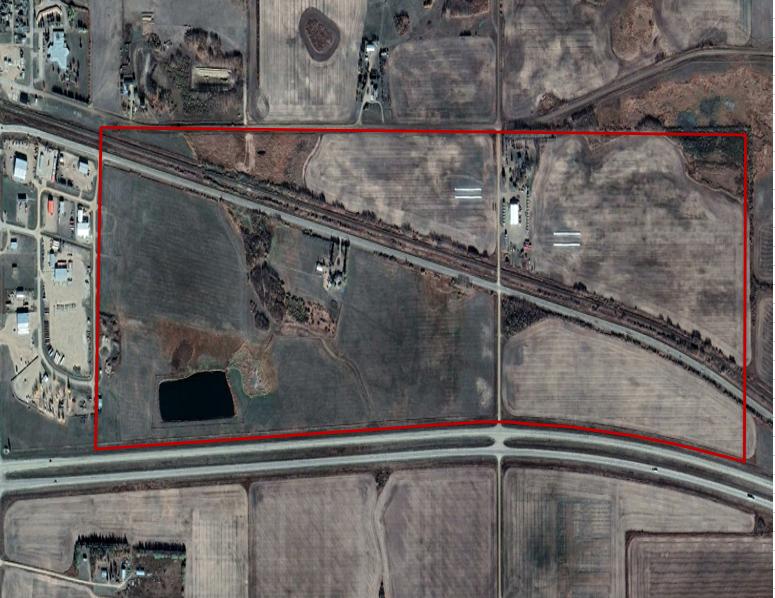
Figure 1 - Aerial Overview Map of the ASP lands area NW & NE-19, NW-20-050-08 W4M.
2 INVENTORY
2.1
Land Use
The current land uses within the future development project footprint include agricultural, wetlands and developed land. The developed land areas consist of residential development. This area is located north as well as south of the Canadian National (CN) rail mainline and Township Road 503B. Highway 16 makes the south boundary of the subject ASP footprint. The natural areas are located intermittently and in small areas within the ASP lands footprint, and are identified as aspen stands, and small wetland areas
2.2 Surrounding Land Use
The current land uses outside of the ASP lands footprint includes agricultural (both cultivated and hayland), commercial and residential (intermittent with natural areas of aspen parkland and less commonly, grassland areas)
2.3 Biological Resources
2.3.1 Natural Region and Soil Characteristics
The ASP lands are found within the Aspen Parkland Ecoregion of east-central Alberta (Strong and Leggat, 1992). Topography varies across the region from nearly level, to gently rolling areas The Central Parkland Natural Subregion is bordered by the Dry Mixed-wood Natural Subregion to the north and west, and the Foothills Fescue, Foothills Parkland, and Northern Fescue Natural Subregions to the south. The Parkland Natural Region consists of highly productive cropland and a vast majority of the region has been cultivated. Areas that have not been converted for agricultural purposes are characterized by a mosaic of aspen and prairie vegetation on remnant native parkland areas (Natural Regions Committee, 2006).
The soil polygon for the area consists of Orthic Black Chernozem on moderately coarse textured (sandy loam) sediments deposited by wind or water. The polygon includes soils with Rego profiles. The landscape for the area is a very gently slope of 15% (Alberta Agriculture and Forestry 2016).
2.3.2 Vegetation
The area of the ASP lands has statistical data gathered by the Government of Alberta between the years of 1971-2000 which indicates the growing season starts between April 17-24 and ends between October 15- 21 (GoA, 2018), lasting between 174 - 187 days. According to the Alberta Soil Information Viewer, the future project development areas have a Land Sustainability Rating System ((LSRS) of 3(10) and 4(8)5W(2)). As per the LSRS for Agricultural Crops, the above-mentioned classifications are as follows:
• 3(10) indicates moderate limitations that restrict the growth of specific crops;
• 4(8) - 5W(2) indicates lands in this area may have severe to very severe limitations that restrict the growth of specific crops, in some areas due to excess water (not due to inundation).
Air photo review indicates the future development area is used for primarily agricultural purposes, varying from crop production to presumed pasture/hay land to support livestock production
A THUNDERCHILD ENERGY SERVICES COMPANY Biophysical Desktop Assessment Project #: 22148 Client: County of Minburn No. 27 Creation Date: August 5, 2022 5
2.3.2 1 Annual Crop Inventory
The 2020 Annual Crop Inventory (Government of Canada 2020) was used to identify vegetation/habitat types for the project area. The digital map shows the area is covered by annual crops (40%), pasture/forage (30%), wetland (15%), water (10%) and broadleaf (5%). (Due to excessive insurance claims, the 2021 data has not all been collected for release)
2.3.2 2 Rare Plant Definition
Rare plants/Indigenous plant species are considered wildlife under the National Wildlife Policy for Canada and must be protected. Government of Alberta standards indicate that vegetation assessments and rare species habitat assessments, if required, will be completed during appropriate surveys.
For this assessment, rare plants refer to the provincial tracking list (Alberta Conservation Information Management System; ACIMS). Plants within the database are rated and follow the NatureServe ranking methodology (ACIMS (Alberta Conservation Information Management System) 2022):
S1: Five or fewer occurrences in the province or may be vulnerable to extirpation because of other factor(s)
S2: Twenty or fewer occurrences in the province or may be vulnerable to extirpation because of other factor(s)
S3: Twenty-one to 100 occurrences in the province or somewhat vulnerable due to other factors, such as restricted range, relatively small population sizes, or other factors.
S4: Apparently secure in present conditions with typically >100 occurrences, may be rare in different parts of province
S5: Secure, common, widespread and abundant
Rare species of S1, S2 and S3 ratings are found across all moisture regimes but are most found in very dry and very wet sites. Locations are dependant on sunlight, soil type and exposure. These features combine to create common habitats where rare and endangered species can be found:
• Groundwater seepage areas (springs, seeps)
• Stream banks
• Steep eroding slopes
• Sandstone outcrops
• Wetlands
• Disturbed ground
• Native grasslands
Within the ASP lands no groundwater seepage areas, stream banks or steep eroding slopes were identified.
A THUNDERCHILD ENERGY SERVICES COMPANY Biophysical Desktop Assessment Project #: 22148 Client: County of Minburn No. 27 Creation Date: August 5, 2022 6
2.3.2
3 ACIMS Database Search
The Alberta Conservation Information Management System (ACIMS) database was searched (online June 16, 2022) for the ASP lands regarding the occurrence of any species at risk. The ACIMS search indicated that there are no non-sensitive or sensitive elemental occurrences within proximity to the ASP lands
2.3.3 Wildlife
2.3.3.1 Wildlife Habitat
Natural Regions Committee 2006 which shows the Natural Regions and Subregions of Alberta was reviewed to determine key wildlife habitat features that could be present in the ASP lands as well as the overall Subregion.
The Aspen Parkland Subregion is a broad arc from southwestern Manitoba, northwest through Saskatchewan to central Alberta.
Specific areas, such as wetlands and riparian habitats, provide key and critical wildlife habitat potential; when planning projects and activities, all efforts must be made to reduce impacts to critical habitats to ensure proposed timing and activities will not detrimentally affect potential avian, fish and/or wildlife habitat.
2.3.3.2 Sensitive Wildlife Database Search
The Fish and Wildlife Internet Mapping Tool (FWIMT; AEP 2022) was used to generate fish and wildlife reports for the ASP lands as well as a 3km radius. These reports show which sensitive wildlife species have been previously documented in the area. To identify which of these species may be of provincial or federal conservation concern, the status of all reported species was then classified according to the General Status of Alberta Wild Species report (Government of Alberta 2017a), the Alberta Wildlife Act and Wildlife Regulation (Government of Alberta 1997; Government of Alberta 2000), the Committee on the Status of Endangered Wildlife in Canada (COSEWIC) and status under the federal Species at Risk Act (SARA) as provided in the Species at Risk Public Registry (Government of Canada 2020).
According to the FWMIS database, no sensitive wildlife species were found within a 3km radius of the centre of the subject area. The FWMIS Search does, however, show the ASP lands occur within a Sharptailed Grouse and Bald Eagle range. There was mention of Sharp-tailed Grouse (Tympanuchus. phasianellus) north-west of the future development and should be noted for future projects.
2.3.4
Environmentally Significant Areas
The ASP lands were reviewed to determine if any Environmentally Significant Areas or other protected areas were within its boundary. ESAs have been defined as places that are vital to the long-term maintenance of biological diversity, soil, water, or other natural processes at multiple scales, that can be used as a strategic conservation tool for land use planning and policy.
According to the provincial dataset no quarter sections within the ASP lands are classed as a provincial ESA. The ASP lands do not contain any provincially designated parks or protected areas (Government of Alberta 2017b).
A THUNDERCHILD ENERGY SERVICES COMPANY Biophysical Desktop Assessment Project #: 22148 Client: County of Minburn No. 27 Creation Date: August 5, 2022 7
2.3.5 Landscape Analysis Tool (LAT) Report
A Landscape Analysis Tool (AER 2015) report was generated for the ASP land area for use during the desktop review. The LAT report identifies the area as a Sharp-tailed Grouse Survey area, as well as identifies that development within 100m of an active nest site between April 15 and August 15 is required for specific grassland bird species. As such, species-specific surveys may be required to be completed as per the Sensitive Species Inventory Guidelines (AEP, 2013). Appendix D
2.3.6 Caveats on Land Title
Land titles were obtained for each property within the Project Area and were assessed for any applicable caveats. No environmental concerns were identified based on the review of the current titles; however, several utility rights-of-way are present (see Appendix D).
2.4 Hydrology, Water Bodies and Wetlands
2.4.1 Hydrology
The project area is located within the North Saskatchewan River Basin (NSR). The NSR originates in the ice fields of Jasper and Banff National Parks and follows the North Saskatchewan River, flowing east towards the Alberta-Saskatchewan border. The North Saskatchewan River basin is divided into 12 watersheds, with the project area located in the Vermilion River watershed near the southern edge of the NSR basin. The Vermilion River watershed covers approximately 7860km², or 14% of the total NSR basin. Farming and oil and gas development are primary economical means as the watershed is home to soils highly suitable for agriculture and petroleum reserves (State of the Watershed Report, North Saskatchewan River Watershed Alliance, 2005).
Vermilion River Watershed and Flood Hazard Map for the project area can be found in Appendix B.
2.4.2 Wetlands
The ASP lands footprint was reviewed using historic air photos and information provided by Alberta Merged Wetland Inventory geospatial dataset (GoA, 2018) for the presence of water features, including wetlands, waterbodies and watercourses. Historic aerial photographs between the years of 1980 to 2021 were reviewed and compared focusing on the presence of, and changes to, sensitive environmental features within the ASP lands footprint wetland and watercourse areas. The photographs were reviewed in combination with relevant climate and precipitation data to provide preliminary wetland delineation and permanency.
In total, eight graminoid marsh wetlands and one ephemeral wetland have been identified within the ASP footprint; it should be noted that the findings of any future field assessments have the potential to identify further wetlands based on soil, vegetation and topography features. It should also be noted that a manmade component is present within the boundaries of wetland 1 (W1); it is believed this area was used as a borrow excavation at some point and is now likely utilized as a dug out for agricultural purposes. The desktop assessment also identified what appear to be two man-made drainage ditches/canals, assumed to have been created to facilitate area drainage. It is unknown if Water Act approval or Licence was obtained for any of the man-made wetland/watercourse features.
The table below is a summary of desktop wetland assessment to include wetland classification and approximate wetland area for portions of wetland within the ASP lands boundary.
A THUNDERCHILD ENERGY SERVICES COMPANY Biophysical Desktop Assessment Project #: 22148 Client: County of Minburn No. 27 Creation Date: August 5, 2022 8
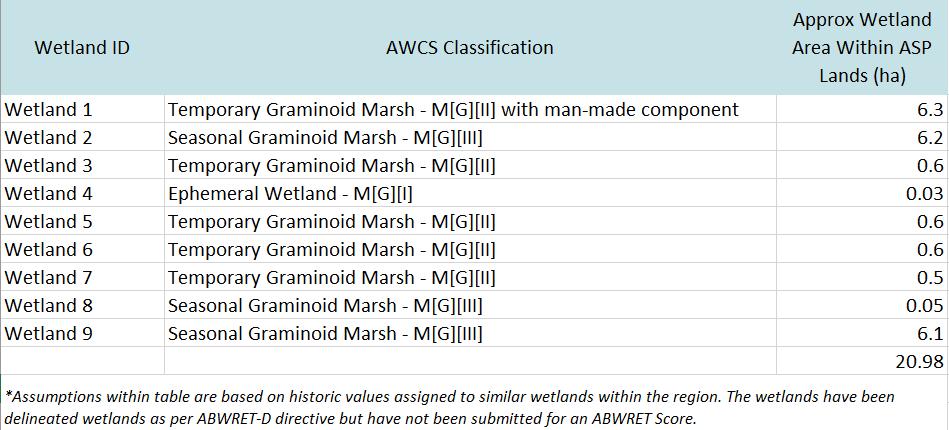
Table 1 – Wetland Assessment Summary
Any wetlands directly impacted by future development will require Water Act (GoA, 2000) approval supported by reporting and documentation as outlined in the Alberta Wetland Policy (GoA, 2013). The historic aerial imagery, including delineations of notable wetlands is located in Appendix C.
In general, wetland classes range from A to D, with D being the lowest valued wetland (AEP, 2016); it is anticipated that the impacted wetlands within the potential developmen t area will be valued as ‘D” wetlands, with slight chance for ‘C’ value in instances of the larger wetland complexes. An Alberta Wetland Rapid Evaluation Tool assessment should take place prior to development of the project area to determine the exact class of wetland, as well as to determine the appropriate mitigation measures for wetland impact.
2.5 Topography
2.5.1 Local and Regional Topography
The regional topography is relatively flat to gently sloping with slopes ranging from 0.5% to 2%. Topography within the ASP footprint is overall generally characteristic of the regional topography of the surrounding area. In general, the topography of the entire region is level to gently sloping slightly rolling with low risk of erosion potential.
2.6 Geology
The surficial geology in the area of the ASP lands is mainly composed of moraine - Diamicton (till) deposited directly by glacial ice with a mixture of clay, silt, and sand, as well as minor pebbles, cobbles, and boulders; characterized by a lack of distinctive topography. Locally, this unit may contain blocks of bedrock, stratified sediment, or lenses of glaciolacustrine and/or glaciofluvial sediment (Fenton et al. 2013)
A THUNDERCHILD ENERGY SERVICES COMPANY Biophysical Desktop Assessment Project #: 22148 Client: County of Minburn No. 27 Creation Date: August 5, 2022 9
Beneath the surficial sediments the composition is Lea Park Formation which is composed of dark shale with minor siltstone. Calcite veins and ironstone concretions as well as bentonite beds are found throughout the formation.
2.7 Cultural and Historical Resources
The Listing of Historic Resources (Alberta Culture and Tourism, May 2022) is a tool that may assist developers, industry representatives and municipalities in determining if a proposed development might affect historic resources. The listing identifies lands that contain or have a high potential to contain historic resources, including archaeological sites, paleontological sites, aboriginal traditional use sites of a historic resource nature (burials, ceremonial sites, etc.), and/or historic structures. The listing can provide proponents with advance notification of possible historic resource concerns and may be used as a tool in planning projects.
The Listing of Historic Resources (accessed online July 2022) was searched for the ASP lands area. The search indicated NW and NE-19 and NW-20-50-8 W4M have no historic resources value (HRV), therefore a Historical Resources Act clearance is not required.
3 EXISTING POLICY
This section provided a summary of municipal policies and federal and provincial legislation that may be applicable to the project. The summary is intended as a guide, but the proponent must ensure that the project adheres to the current policies, plans and legislation at the time of development as they are subject to change.
3.1 Municipal Land Use
3.1.1 County of Minburn Intermunicipal Development Plan
The County of Minburn consists of the Hamlet of Lavoy, the Hamlet of Ranfurly, the Hamlet of Minburn, the Village of Innisfree, the Village of Mannville, the Town of Vegreville and surrounding rural areas. The Intermunicipal Development Plan (IDP) was adopted by the County of Minburn and Village of Mannville to investigate any potential areas of mutual interest in a joint planning area. The ASP lands area is within the area identified in the IDP.
3.1.2 County of Minburn Municipal Development Plan
The Municipal Development Plan (MDP) outlines any potential for altering land uses throughout the county and guidance for the type of development required to do so. This is completed with planning goals to maintain the balance of conservation of existing agricultural areas along with development of economics.
3.2 Provincial
3.2.1 Environmental Protection and Enhancement Act
The Environmental Protection and Enhancement Act, RSA 2000, c. E-12 (EPEA) supports and promotes the protection, enhancement and wise use of Alberta’s environment. Only those activities designated in the EPEA Schedule of Activities are subject to EPEA. The development of certain projects requires either an
A THUNDERCHILD ENERGY SERVICES COMPANY Biophysical Desktop Assessment Project #: 22148 Client: County of Minburn No. 27 Creation Date: August 5, 2022 10
Environmental Impact Assessment (EIA) report, approval, registration, or notification under EPEA. A list of mandatory activities that require an EIA is located in the Environmental Assessment (Mandatory and Exempted Activities) Regulation, Alta Reg 111/1993. This regulation also lists activities which are exempt from an EIA, or are discretionary (not on either list and require a decision by the Director). The Activities Designation Regulation, Alta Reg 276/2003 lists activities that require an approval, registration, or notification under EPEA. Whether or not activities on the ASP lands will need an application under EPEA will depend on the specifics of the development.
3.2.2 Municipal Government Act
Under the Municipal Government Act, RSA 2000, c. M-26, section 664(1), a municipality may require a portion land subject to a proposed subdivision to be retained in its natural state as environmental reserve if it consists of:
a) A swamp, gully, ravine, coulee, a natural drainage course.
b) Land that is unstable or subject to flooding.
c) A strip of land adjacent to the bed and shore of any water body, no less than 6 m in width. This includes any lake, river, stream or other body of water.
A municipal government can designate land as environmental reserve for the purpose of preserving natural land features, to prevent pollution of the land or body of water, to endure public access to the waterbody, or to prevent development where natural features may pose a risk to personal safety or property.
3.2.3 Public Lands Act
All Crown land, including the bed and shores of all permanent watercourses and water bodies, are considered Alberta public lands unless they are owned by the Government of Canada. As such, approvals from AEP under the Public Lands Act, RSA 2000, c. P-40 are required for any activity on public lands or the bed or shore of Crown owned rivers, streams, or lakes. A list of activities that require a Public Lands Act approval is available from the AEP website.
3.2.4
Water Act
All water resources located within the province of Alberta are owned by the Provincial Government. AEP administers the Alberta Water Act, RSA 2000, c. W-3, which is the primary legislation governing the use and management of Alberta’s water resources, including wetlands. Alberta’s Water Act requires approval, code of practice notification, and/or attainment of a license before undertaking construction in a surface water body or activities related to a water body which have the potential to impact the aquatic environment.
A Water Act Code of Practice Notification is required for specific activities that adhere to the Codes of Practice. There are four types of activities that have an associated Code of Practice:
• Code of Practice for Pipelines and Telecommunication Lines Crossing a Water Body
• Code of Practice for the Temporary Diversion of Water for Hydrostatic Testing of Pipelines
• Code of Practice for Watercourse Crossings
A THUNDERCHILD ENERGY SERVICES COMPANY Biophysical Desktop Assessment Project #: 22148 Client: County of Minburn No. 27 Creation Date: August 5, 2022 11
• Code of Practice for Outfall Structures on Water Bodies
Specific construction and mitigation standards/conditions are outlined within the codes of practice that vary depending on the type of activity and the class of the waterbody being impacted. If the requirements outlined in the Code of Practice cannot be followed, the project must obtain approval under the Water Act.
Wetland management in Alberta is regulated through Section 36 of Alberta’s Water Act. A Water Act approval is required prior to any works that may impact a wetland. AEP released Alberta’s new Wetland Policy in September 2013, which applies to all wetlands in the province. Applicants proposing an activity in a wetland must submit a wetland assessment to the regulatory body with the application and other required plans. Most activities will require an Alberta Wetland Assessment and Impact Report (WAIR) to be prepared by an Authenticating Professional to be submitted with the application. Certain low risk activities allow an Alberta Wetland Assessment and Impact Form (WAIF) to be submitted in plac e of a WAIR. The Alberta Wetland Rapid Evaluation Tool – Actual (ABWRET-A) must be used when a WAIR is required to determine the relative value of the wetland, which is then used to inform decisions about avoiding high-value wetlands and determines cost and replacement ratios for wetland replacement when avoidance is not possible. The Alberta Wetland Rapid Evaluation Tool – Desktop (ABWRET-D) can be used when a WAIF is required for the activity
3.2.5
Weed Control Act
The Alberta Weed Control Act, SA 2008, c.W-5.1 regulates noxious weeds, prohibited noxious weeds, and weed seeds through inspection and enforcement measures, as well as outlines provisions for cases of noncompliance. The Act requires that a person must control noxious weeds and destroy prohibited noxious weeds that are on a property they own or occupy, as well as not facilitate the spread of weeds or weed seeds. The plant species listed in Schedule 1 of the Weed Control Regulation, Alta Reg 19/2010 are designated as prohibited noxious weeds in Alberta, and those listed under Schedule 2 are listed as noxious weeds in Alberta.
3.2.6 Wildlife
Act
Alberta’s Wildlife Act, RSA 2000, c.W-10 protects the residences of wildlife on private and public lands. More specifically, a person must not wilfully molest, disturb or destroy a house, nest, or den of prescribed species. Section 96 of the Wildlife Regulation, Alta Reg 143/1997 outlines the wildlife species, areas, and time of year when the Act applies. All endangered wildlife, upland game birds, some migratory birds, snake and bat dens, and beavers (in some instances) are species of which Section 36 of the Act applies to. For most wildlife, disturbing the habitat of these animals is prohibited year-round throughout Alberta. AEP staff may recommend timing restrictions on activities to minimize disturbance to the nest of breeding wildlife and birds. The Wildlife Act also protects endangered plant species (both vascular and nonvascular) listed in the Wildlife Regulation.
3.3 Federal
3.3.1 Fisheries Act
The Fisheries Act, RSC 1985, c. F-14 applies to all Canadian fisheries waters and Fisheries and Oceans Canada (DFO) has the responsibility to administer and enforce the conservation and protection of fish
A THUNDERCHILD ENERGY SERVICES COMPANY Biophysical Desktop Assessment Project #: 22148 Client: County of Minburn No. 27 Creation Date: August 5, 2022 12
habitat on private property, as well as on provincial and federal lands. Section 36(3) of the Fisheries Act prohibits the discharge of deleterious substances into a water body frequented by fish; Section; Section 35(1) prohibits any work or activity that results in harmful alteration, disruption, or destruction of fish habitat; and Section 34.4(1) states that no person shall carry on any work, undertaking or activity, other than fishing, that results in the death of fish.
DFO has provided a list of measures to protect fish and fish habitat that apply to clear span bridges, bridge maintenance, on-land mineral exploration activities, and decking repairs. If a project can’t completely implement the measures and doesn’t fall under the standards and codes of practice, a request for project review must be sent to DFO. Activities that are covered under the standards and codes of practice include: beaver dam removal, culvert maintenance, fish protection screens, routine maintenance dredging, temporary cofferdams and diversion channels, and temporary stream crossings. If a project can follow all procedures, practices, and standards within the standards and codes of practice, a notification form must be submitted to DFO.
If a project does not meet the criteria established by DFO to avoid serious harm to fish and the effects cannot be mitigated by an applicable standards and codes of practice, a Request for Review must be submitted for consideration by the Minister of Fisheries and Oceans. If activities are determined to cause serious harm to fish, an Application for Authorization will be required that will include a fish and fish habitat report, available design information, a description of effects on fish and fish habitat, a description of measures and standards to avoid or mitigate serious harm to fish and an offsetting plan.
3.3.2 Migratory Birds Convention Act
The Migratory Birds Convention Act, SC 1994, c. 22 (MBCA) and Migratory Birds Regulations, CRC, c. 1035 prohibit the harm of migratory birds, their nests, eggs, and habitat. Environment Canada recommends timing restrictions and setbacks to help identify when the risk of contravening the MBCA is particularly high. According to the Map of Nesting Zones in Canada (Government of Canada 2017), the ASP lands area is located in Nesting Zone B4 withing the Prairie Bird Conservation Region. In this nesting zone, birds are actively nesting between April 14 and August 28 (Government of Canada 2017), with some variation between different bird species and habitat types.
Environment Canada advises that habitat destruction activities (e.g., vegetation clearing, flooding, draining, construction, etc.) in areas attractive to migratory birds are prohibited during the active nesting period to reduce the risk of contravening the MBCA. In select cases where vegetation is open and nests can be readily identified (e.g., a few trees in a city park or isolated patch of trees), a wildlife sweep can be conducted by a qualified biologist prior to beginning activities to ensure no nests are within the area to be disturbed, and no contraventions under the MBCA occur.
The MBCA and its associated regulation specify that efforts should be made to preserve and protect habitat necessary for the conservation of migratory birds. This includes nesting and wintering grounds, migratory bird corridors, and encompasses such activities as tree clearing, wetland consolidation, and temporary and permanent disturbances occurring in proximity to migratory bird habitat.
A THUNDERCHILD ENERGY SERVICES COMPANY Biophysical Desktop Assessment Project #: 22148 Client: County of Minburn No. 27 Creation Date: August 5, 2022 13
3.3.3
Species at Risk Act
The Species at Risk Act, SC 2002, c. 29 (SARA) provides protection for species listed as “Endangered” or “Threatened” under the Act. Protections for these species under SARA only apply on federal lands (oceans and waterways; national parks; military training areas; national wildlife areas; some migratory bird sanctuaries; and First Nations reserve lands). SARA does not apply to lands held by the Province of Alberta or its private citizens unless “the laws of Alberta do not effectively protect the species or the residences of its individuals”. The Minister may issue an order in council to protect federally listed species that occur on provincial or private lands, but his has not occurred within the ASP lands or surrounding area.
4 IMPACTS MITIGATIONS AND MONITORING
4.1 Impact Assessment Results
4.1.1 Potential Impact to
Vegetation
Almost exclusively non-native vegetation makes up the ASP lands with the exception of the semipermanent marshes and ditch areas. For this reason, the potential impact on vegetation is minimal. Soil disturbance during the construction of the new development welcomes potential for invasive species and a weed control program should be developed for any future development activities of the ASP lands
4.1.2 Potential Impact to Wildlife
It is recommended that a pre-construction wildlife sweep be conducted within 7 days prior to the onset of vegetation clearing or construction activities if activities are to be carried out between April 1st and August 15th.
The residual effects of the project on wildlife are anticipated to be low. Overall, impacts on wildlife are expected to be relatively minimal due to the proximity of the project to existing developments and location on agricultural lands. However, temporary indirect impacts on wildlife may result from increased noise and stimuli extending for distances into adjacent habitats. This noise and stimuli may cause edge effects, resulting in some species avoiding areas of adjacent habitats during construction. The impacts of disturbances associated with potential future development may cause some wildlife species to favor or avoid areas adjacent to the project during the activity. However, these residual impacts are expected to be low due to the high level of development in the surrounding area.
4.1.3 Potential Impact to Hydrology
As the ASP lands are being converted, there is a possibility of natural surface water absorption becoming more limited. This could be alleviated by retaining some wetlands within the new landscape.
4.1.4 Potential Impact to Wetlands
Based on the assessment future development plans, nine wetlands within the ASP lands have been identified.
As per the Alberta Wetland Mitigation Directive, the most desired option for any wetland is avoidance. There are many instances where avoidance is the only option considered, crown ownership, special designated lands, presence of endangered species, etc. For purpose of this BEA, avoidance of wetlands is likely not feasible as future development plans may encompass several wetlands.
A THUNDERCHILD ENERGY SERVICES COMPANY Biophysical Desktop Assessment Project #: 22148 Client: County of Minburn No. 27 Creation Date: August 5, 2022 14
Minimization is the second preference when planning a project if avoidance is not possible. It refers to minimizing both the direct and indirect effects on the wetland and the value of the wetland during the future development plans. For purpose of this BEA, minimization of wetland impacts may be feasible as development plans may be altered to reduce impacts to the wetlands within the ASP lands. In order to achieve this goal, alternate activities may be considered, or development plans may be modified. Water Act Approval, and other related applications and approvals under the Act, are required if the wetland under the minimization strategy option.
If permanent wetland loss is expected, a Replacement Proposal must accompany the Water Act application. The desktop delineation identified nine wetlands within the project area totalling approximately 21ha. The desktop assessment also identified what appear to be two man-made drainage ditches/canals, assumed to have been created to facilitate area drainage. In the event these wetlands are eliminated due to potential future development, a replacement payment may be required; this would be required to be submitted to the Wetland Replacement Agency for this area. This area of Alberta falls under the in-lieu fee rate of $18,600.00/ha, and the in-lieu fees would be payable to the Wetland Replacement Agency for this area. The approximate potential in-lieu fees per wetland are itemized within the table below:
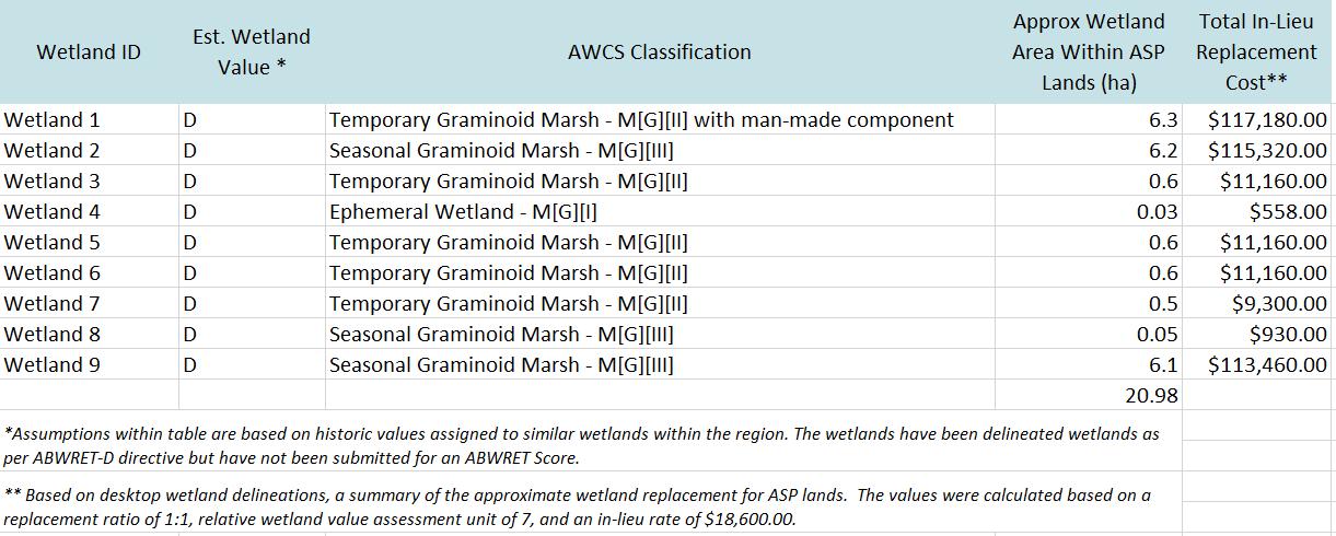
In addition, any permanent or semi-permanent, shallow open water or marsh wetlands are likely to have their ownership claimed by the provincial Crown under Section 3 of the Public Lands Act (GoA, 2000). Further investigations and regulatory applications may be required for assessing the permanence of the wetlands situated within the proposed development area
4.1.5
Topography Impact
It is anticipated that future development of the ASP lands will have minor impacts to the topography at the regional scale, due to the already present, relatively flat conditions. It is assumed that grading, soil stripping, and infill would occur during future development, therefore, there will likely be an impact at
A THUNDERCHILD ENERGY SERVICES COMPANY Biophysical Desktop Assessment Project #: 22148 Client: County of Minburn No. 27 Creation Date: August 5, 2022 15
Table 2 – Wetland Loss Replacement Proposal
the local scale. Due to the lack of ravines, coulees, and or escarpments (of greater than 15% slope), no mitigation measures are currently required at an Environmental Assessment stage.
4.1.6 Geographical and Geological Impact
It is anticipated that future development of the ASP lands will have negligible impacts to the geography and geology, due to the specific landscape position and the landscape features around the ASP lands area. No unique landforms were identified. No major disruption, in general, of regional drainage patterns are expected due the relative flat nature of the geographic landforms.
Localized minor impacts would be expected. Also, due to no known mapped bedrock surface exposures, no mitigation measures are required for geographical and geological impacts
4 1 7 Historical Resources Impact
The Alberta Listing of Historic Resources Spring 2022 Edition (csw-listing-of-historic-resources-spring2022-03) was reviewed for the subject lands; the future development area does not have an HRV value. If historic resources are discovered during development activities, findings must be reported to the Heritage Division of Alberta Culture, Multiculturalism and Status of Women before continuing work.
4 1 8 Socio-Economic Impact
There is potential for the future development of the ASP lands to disturb the surrounding community, however this disturbance will be low and effect more commercial areas than residential. There is potential for noise disturbance, interrupted usage of certain roads in the area and potential of construction waste on-site. Disturbances will be short-term, and the long-term impact will be an economic growth potential for the community.
4.2 Impact Assessment and Recommendations
The ASP lands area is somewhat disturbed with roads, farms and other developments. Future development will shift the land use from agriculture to rural industrial and commercial which will cause a loss of vegetation. Although this could cause a reduction of breeding opportunities for grassland birds and small mammals, much of the areas surrounding the ASP lands area are similar quality habitats. If any impacts to wetlands are to occur, Water Act approval is required. In addition to Water Act approval, wetland replacement is required for the disturbance of all wetlands (excluding ephemeral wetlands), and in-lieu fees may be required for permanent impacts to wetlands. In addition, any permanent or semipermanent, shallow open water or marsh wetlands, are likely to have their ownership claimed by the provincial Crown under Section 3 of the Public Lands Act (GoA, 2000).
The ASP lands are located within Sharp-tailed Grouse range and have the potential for other sensitive and species of concern to occur in the project area. Prior to development activities, sensitive species surveys are to be conducted as per the applicable Sensitive Species Inventory Guidelines (GOA, 2013).
All activities pertaining to future development of the ASP lands must follow the Migratory Bird Convention Act. A pre-construction wildlife and nest sweep is recommended within 7 days prior to the onset of any future development activities.
A THUNDERCHILD ENERGY SERVICES COMPANY Biophysical Desktop Assessment Project #: 22148 Client: County of Minburn No. 27 Creation Date: August 5, 2022 16
Noise, access issues and other potential disturbances from development will be short-term and will be outweighed by the long-term socio-economic impacts the ASP lands area will have on the region when complete.
Appropriate planning, the use of current best practices, knowledgeable/experienced supervisors and equipment operators will help mitigate the potential impacts on soil such as compaction, erosion, significant soil loss, severe admixing and reduces soil quality. Prior to any development activities, it would be beneficial to develop specific plans such as an environmental construction and operational plan that outline strategies to protect the soil, minimize erosion, retain, and re-establish vegetation, and control invasive weed species. Also, a construction/development plan should be developed to include strategies to minimize the initial environmental impacts and reduce the overall environmental footprint caused by future development activities.
4.3 Conclusion
On behalf of the County of Minburn No. 27, X-Terra Environmental Services Ltd. completed a Biophysical Environmental Assessment (BEA) of ASP lands within the NW-19, NE-19 and NW-20-050-08 W4M, east of Mannville, Alberta.
The information gathered throughout the BEA including the proposed preliminary development plans were interpreted to determine the potential for negative environmental impacts that may result from the future development activities. Findings revealed that significant environmental features were not present within the above mentioned ASP areas.
A THUNDERCHILD ENERGY SERVICES COMPANY Biophysical Desktop Assessment Project #: 22148 Client: County of Minburn No. 27 Creation Date: August 5, 2022 17
5 EVALUATION OF INFORMATION AND REPORTING
This report has been prepared and the work referred to within, has been undertaken by X-Terra Environmental Services Ltd. (X-Terra) for the named client using generally accepted environmental consulting practices. The material within reflects X-Terra’s best judgment based on the material available at the time of preparation. It is intended for the exclusive use of the client, its affiliated companies and partners, their respective insurers, agents, employees, advisors, and applicable regulatory agencies. Any use, reliance on, or decision based on this report made by any person other than those identified above, is the sole responsibility of such other person. X-Terra makes no representation or warranty to any other person with regard to this report and the work referred to within and accepts no duty or care to any other person or any liability or responsibility whatsoever for any losses, expenses, damages, fines, penalties, or other harm that may be suffered or incurred by any other person as a result of the use of, reliance on, any decision made, or any action taken based on this report, or the work referred to in this report.
The work performed by X-Terra with respect to this report and any conclusions or recommendations made in this report reflect X-Terra’s judgment based on the conditions observed at the time set out in this report and on information available at the time of preparation. Unless otherwise stated, the findings cannot be extended to previous or future site conditions, where applicable, or to areas not directly assessed within the scope of work. Environmental conditions, other than those addressed by the investigation described in this report, may exist within the site. If site conditions or applicable standards change or if any additional information becomes available at a future date, modifications to the findings, conclusions and recommendations in this report may be necessary.
Other than by the named client, copying or distribution of this report or use of or reliance on the information contained herein, in whole or in part, is not permitted without the expressed written permission of X-Terra which will not be unreasonably withheld. Nothing in this report is intended to constitute or provide a “legal opinion.”
Any intellectual property arising from the preparation of this report will vest with the client. In all cases where X-Terra is liable to any third party for any information set out or omitted from this report, the total liability of X-Terra, whether for direct, indirect, consequential, aggravated, and punitive damages and all legal costs, shall not exceed the amount paid to X-Terra for the preparation of this report.
A THUNDERCHILD ENERGY SERVICES COMPANY Biophysical Desktop Assessment Project #: 22148 Client: County of Minburn No. 27 Creation Date: August 5, 2022 18
REFERENCES
ACIMS (Alberta Conservation Information Management System). 2022. List of Elements in AlbertaVascular Plants. Alberta Environment and Parks, Edmonton, Alberta. [accessed 2022 June 16] https://www.albertaparks.ca/albertaparksca/management-land-use/alberta-conservation-informationmanagement-system-acims/download-data/#trackedWatch
Alberta Environment and Parks (AEP). 2022. Fisheries and Wildlife Management Information System (FWMIS) Internet Mapping Tool. [accessed 2022 June 16] https://geospatial.alberta.ca/FWIMT_Pub/Viewer/?TermsOfUseRequired=true&Viewer=FWIMT_Pub
AESRD. 2015. Alberta Wetland Classification System. Edmonton, AB: Water Policy Branch, Policy and Planning Division.
ANPC. 2012. Guidelines for Rare Vascular Plant Surveys in Alberta 2012 UPDATE. Edmonton, AB: Alberta Native Plant Council. [accessed 2019 Mar 8]. http://www.anpc.ab.ca/content/resources.php%0A
COSEWIC. 2010. COSEWIC Assessment and Status Report on the Western Blue Flag Iris missouriensis in Canada. Ottawa, Ontario: Committee on the Status of Endangered Wildlife in Canada.
Fenton MM, Water EJ, Pawley SM, Atkinson N, Utting D., McKay K. 2013. Surficial Geology of Alberta. Map 601. Alberta Geological Survey. Alberta Energy Regulator
Government of Alberta. 2014. Alberta Soil Information Viewer. Agricultural Region of Alberta Soil Inventory Database (AGRASID). https://soil.agric.gov.ab.ca/agrasidviewer/.
Government of Alberta. 2015. Alberta Wetland Identifiction and Delineation Directive. Edmonton, Alberta: Water Policy Branch, Alberta Environment and Parks.
Government of Alberta. 2022a. Listing of Historic Resources. June 2022. [accessed 2022 June 16]. https://www.alberta.ca/listing-historic-resources.aspx.
Government of Canada. 2020. Annual Crop Inventory, 2020. Agriculture and Agri-Food Canada.
Stewart RE, Kantrud HA. 1971. Classification of natural ponds and lakes in the glaciated prairie region. Washington, D.C., U.S.A: Northern Prairie Wildlife Research Center, Division of Wildlife Research. Resour Publ.
A THUNDERCHILD ENERGY SERVICES COMPANY Biophysical Desktop Assessment Project #: 22148 Client: County of Minburn No. 27 Creation Date: August 5, 2022 19
APPENDIX
A:
FIGURE 2: PROJECT LOCATION OVERVIEW
A THUNDERCHILD ENERGY SERVICES COMPANY Biophysical Desktop Assessment Project #: 22148 Client: County of Minburn No. 27 Creation Date: August 5, 2022 A
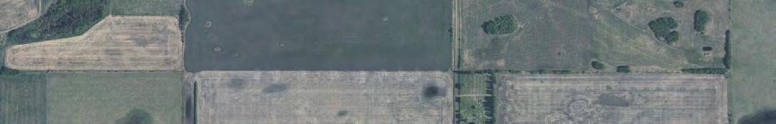
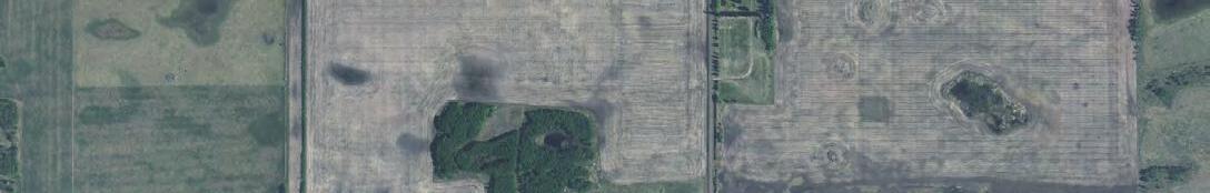
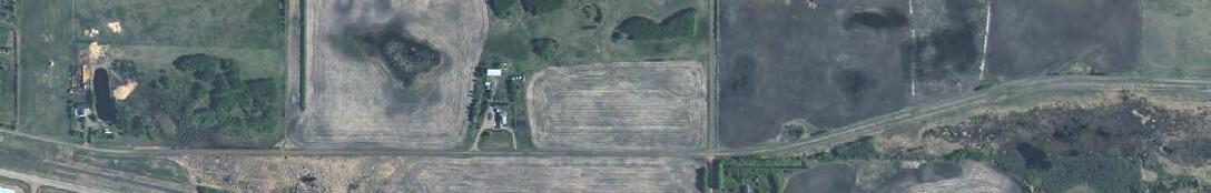
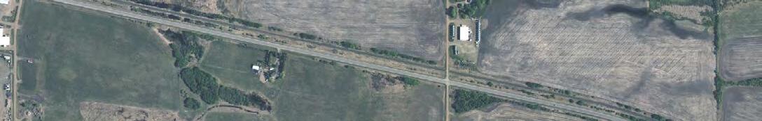
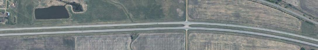
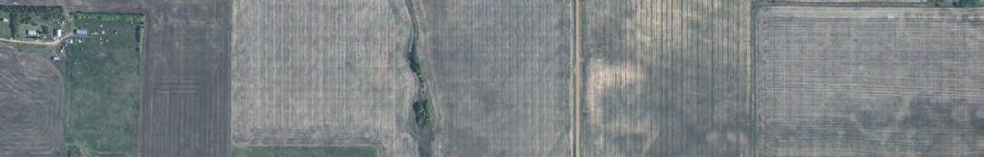


640 630 620 620 630 630 630 630 19 20 29 30 FIGURE: TITLE: PROJECT: S:\GIS\2022_Projects\County of Minburn\22148_County of Minburn(Red Willow) ASP 2022\MXDs\1Report\22148 COUNTY OF MINBURN RED WILLOW.mxd 0 500 M RED WILLOW PROJECT OVERVIEW 2 REFERENCE: NATURAL RESOURCES CANADA, CENTRE FOR TOPOGRAPHIC INFORMATION, 2012; ALBERTA ENVIRONMENT AND SUSTAINABLE RESOURCE DEVELOPMENT AIR PHOTO DISTRIBUTION; GOOGLE EARTH, ESRI, BING IMAGERY NAD_1983_10TM_AEP_FOREST QUARTERSECTION PROJECT FOOTPRINT VILLAGE OF MANVILLE WETLAND BOUNDARY HIGHWAY WATER LINE PRIMARY POWER LINE CONTOUR LINE (10M) CONTOUR LINE (1M) LEGEND DATE DRAWN 2022-08-04 DATUM PROJECTION NAD 83 UTM Z12 SCALE 1:12,500 JC REVIEWED VERSION R1 CB 10TM AEP F
APPENDIX
B: WATERSHED/FLOOD HAZARD MAP
A THUNDERCHILD ENERGY SERVICES COMPANY Biophysical Desktop Assessment Project #: 22148 Client: County of Minburn No. 27 Creation Date: August 5, 2022 B
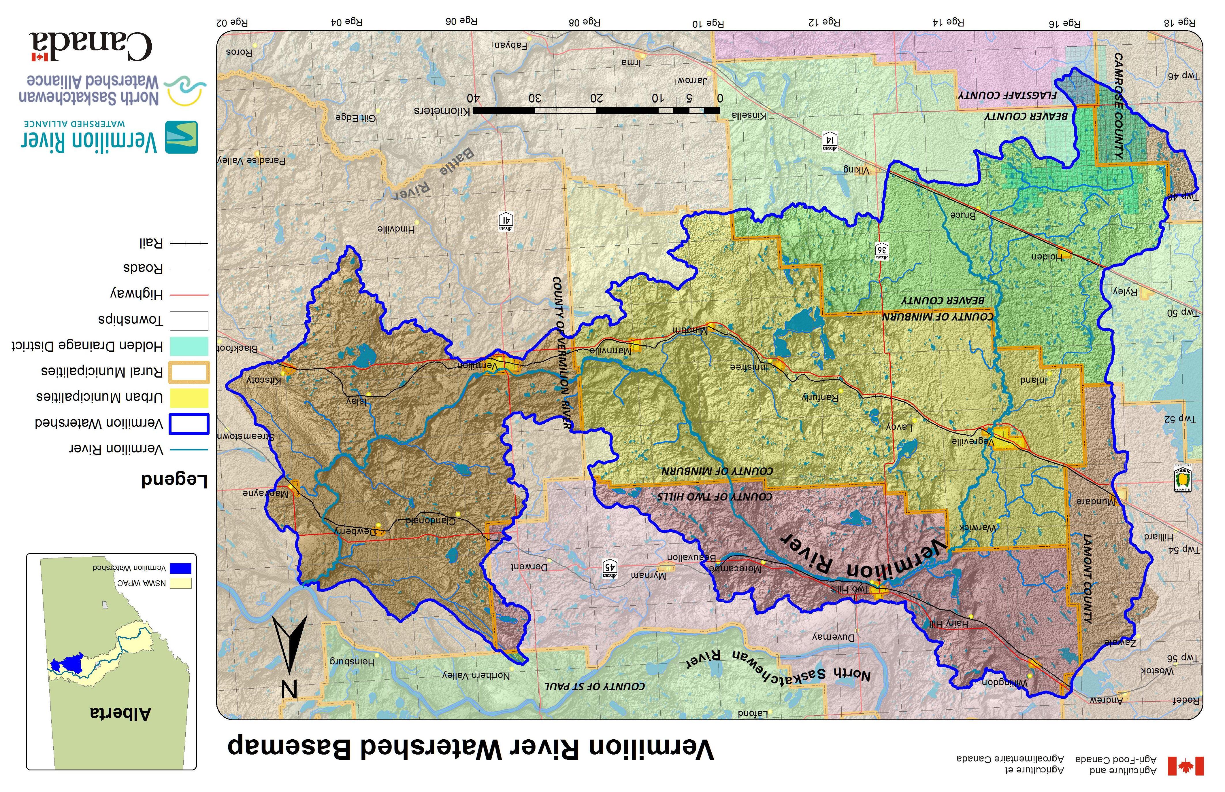

Design Flood
Flood Hazard Map
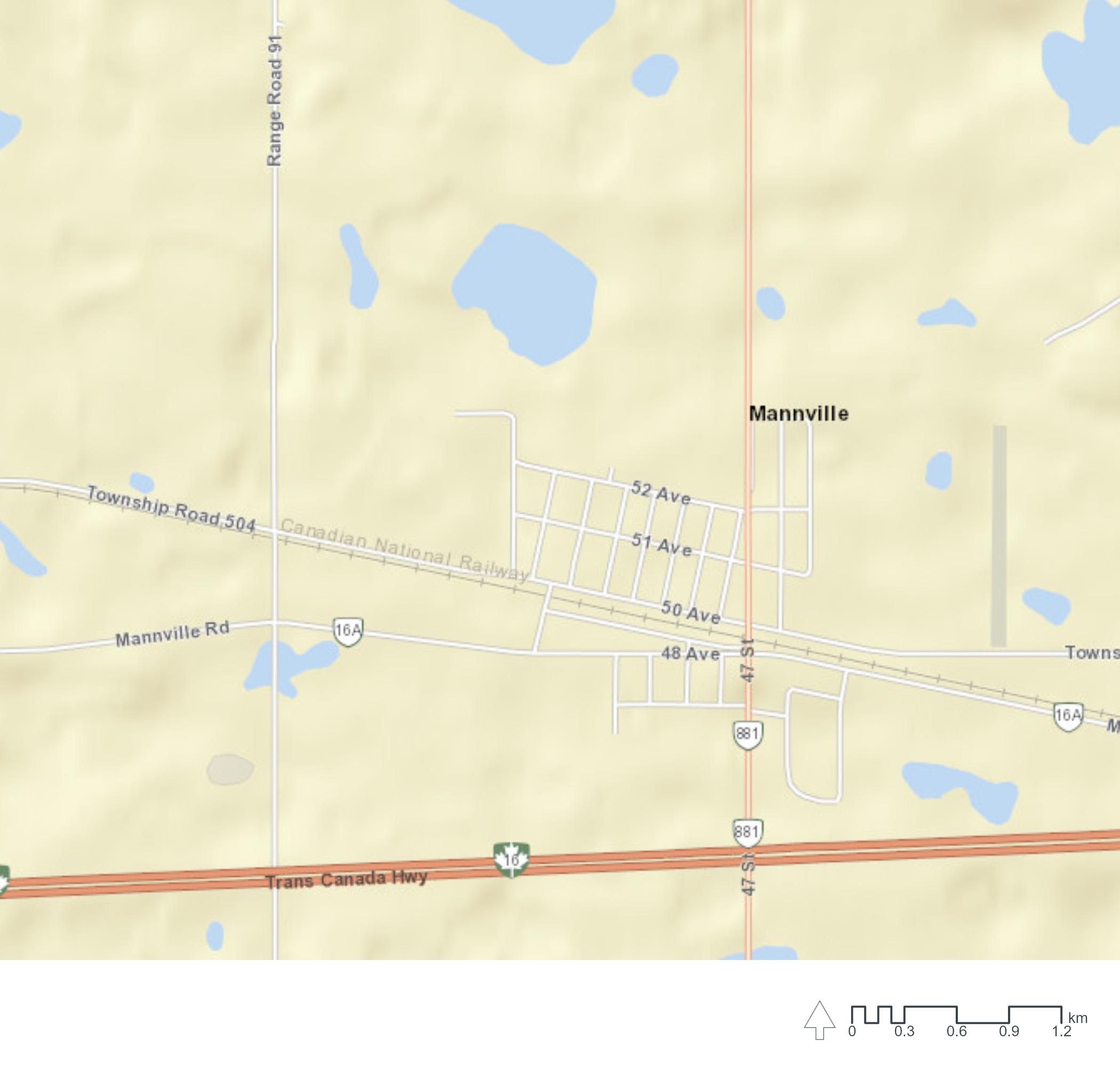


Floodway
Flood Fringe
Overland Flow (Flood Fringe)
Under Review
Cross Section and Design Flood Level
Map Projection: Mercator Auxiliary Sphere
Map Datum: World Geodetic System 1984
Flood Level Datum: Canadian Geodetic Vertical Datum of 1928
The flood information as depicted is subject to change, therefore the Government of Alberta assumes no responsibility for discrepancies at the time of use.
| Printed July 18, 2022
Page 1 of 2 ©2022 Government of Alberta | floods.alberta.ca
Flood Hazard Maps
Flood hazard maps define floodway and flood fringe areas for the 1:100 design flood. These maps are typically used for long range planning and to make local land use decisions, and are available to all levels of government and the public to help build resilient communities.
Flood Study Details
Vegreville Flood Hazard Study
This study assesses and identifies flood hazards along 14 km of the Vermilion River and 13 km of an unnamed tributary through Vegreville. Open water flooding is the design condition for this study. The design flow for the Vermilion River and the unnamed tributary are 73.0 m³/s and 3.3 m³/s respectively.
Study Status: Final
Report Name: Vegreville Flood Risk Mapping Study
Report Author: SNC-Lavalin Inc., Edmonton, Alberta
Report Date: April 1994
Limitations
The flood extents shown on this map are not expected to match previous floods due to different river flows, variations in local conditions, and assumptions made as part of the flood study. The flood mapping and other information presented were prepared in accordance with generally accepted engineering practices, using the best data available when the flood study was conducted. Information is subject to change, and the Government of Alberta assumes no responsibility for discrepancies at the time of use.
Contact Us
For more information about flood maps and the provincial Flood Hazard Identification Program please visit www.floodhazard.alberta.ca or email us at aep.flood@gov.ab.ca.
| Printed July 18, 2022
Page 2 of 2 ©2022 Government of Alberta | floods.alberta.ca
APPENDIX C: FIGURE 3: WETLAND DELINEATIONS/HISTORIC AERIAL
A THUNDERCHILD ENERGY SERVICES COMPANY Biophysical Desktop Assessment Project #: 22148 Client: County of Minburn No. 27 Creation Date: August 5, 2022 C
IMAGERY
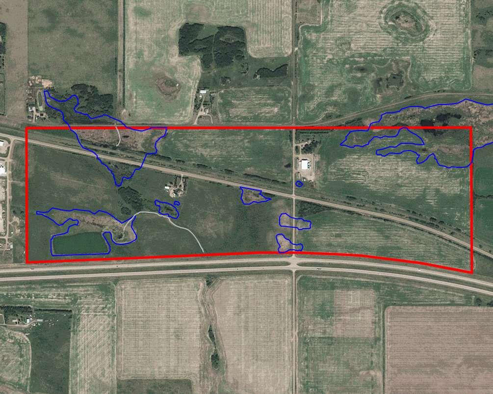
DESCRIPTION
PhotoDescription:2019AbadataAerialImage
X-TerraFileNo.: 22148
LEGEND
ASPLands:

DesktopDeliniatedWetland/Tributary: DrainageDitch/Canal CountyofMinburnNo.27
REFERENCE
2019Abadata
BiophysicalEnvironmental Assessment
 FIGURE1
NOTTOSCALE W2 W3 W4 W1 W5 W6 W7 W8 W9
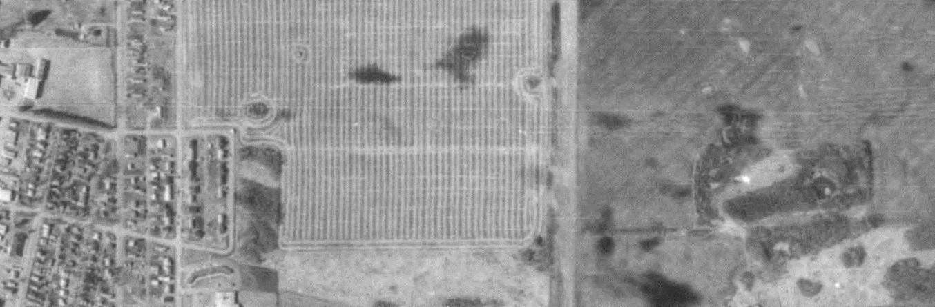
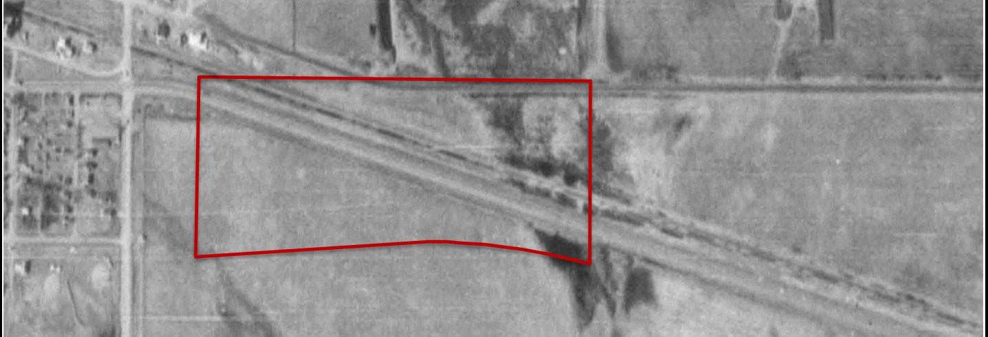
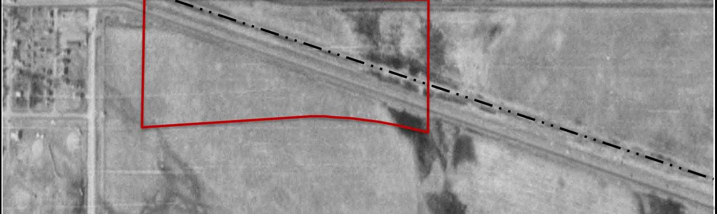
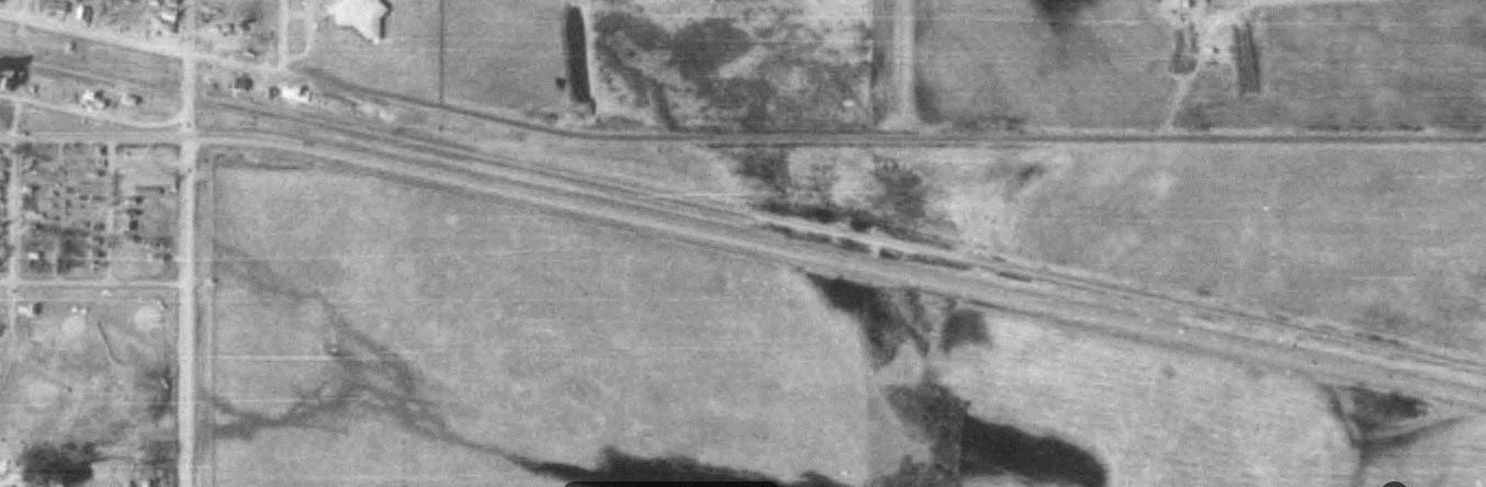
DESCRIPTION
PhotoDescription:1980AirPhoto
X-TerraFileNo.: 22148
LEGEND
ProposedProjectArea:
Railway: Highway:
REFERENCE
1980AER


Scale:1:17,000

CountyofMinburnNo.27
BiophysicalEnvironmental Assessment
FIGURE1
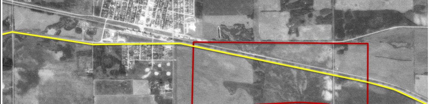
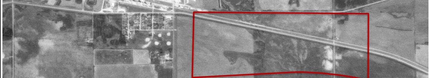
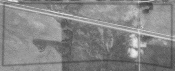
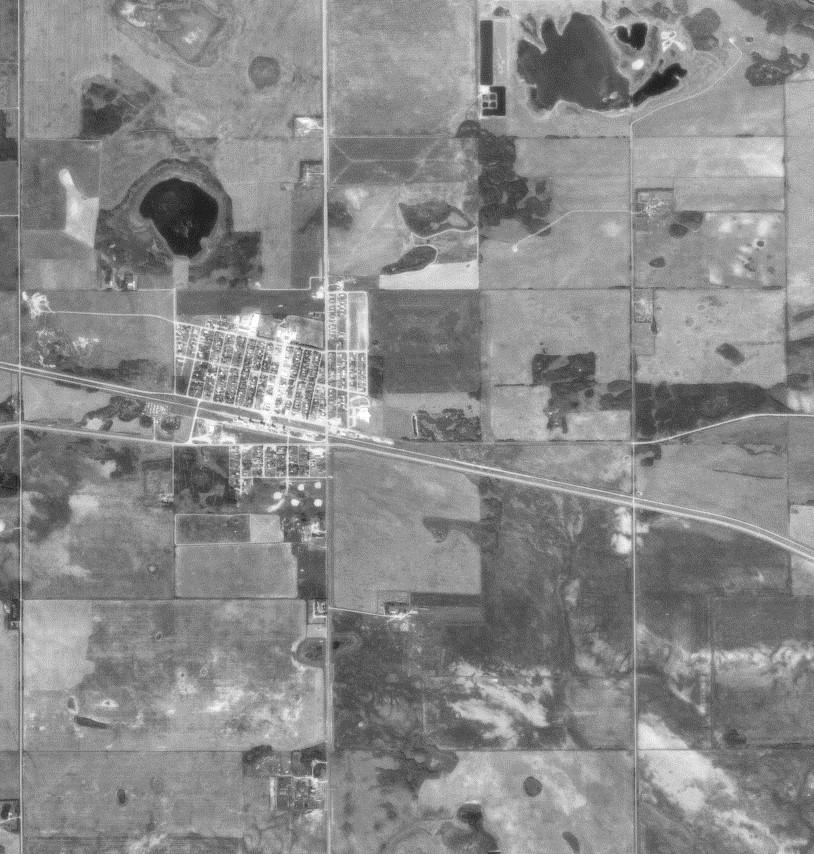
DESCRIPTION
PhotoDescription:1983AirPhoto
X-TerraFileNo.: 22148
LEGEND
ProposedProjectArea:
Railway: Highway:
REFERENCE
1983AER


Scale:1:19,000
CountyofMinburnNo.27
BiophysicalEnvironmental Assessment
FIGURE2
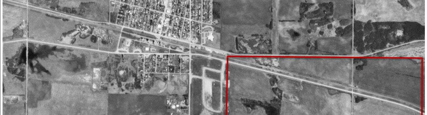
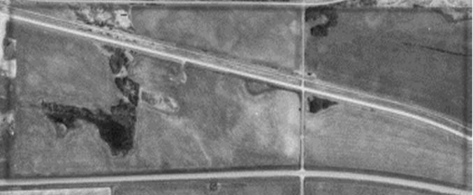
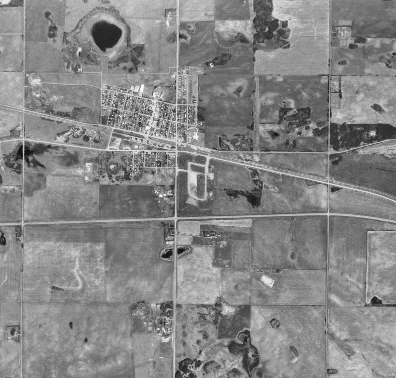
DESCRIPTION
PhotoDescription:1987AirPhoto
X-TerraFileNo.: 22148
LEGEND
ProposedProjectArea:
Railway: Highway:
REFERENCE
1987AER

Scale:1:16,000
CountyofMinburnNo.27
BiophysicalEnvironmental Assessment
FIGURE3
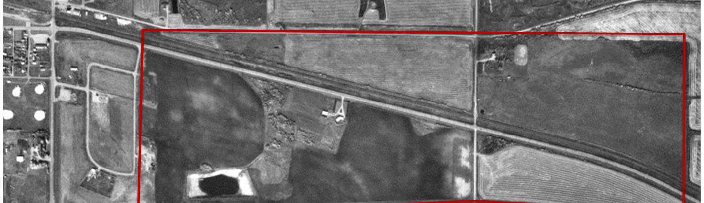
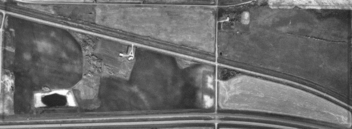
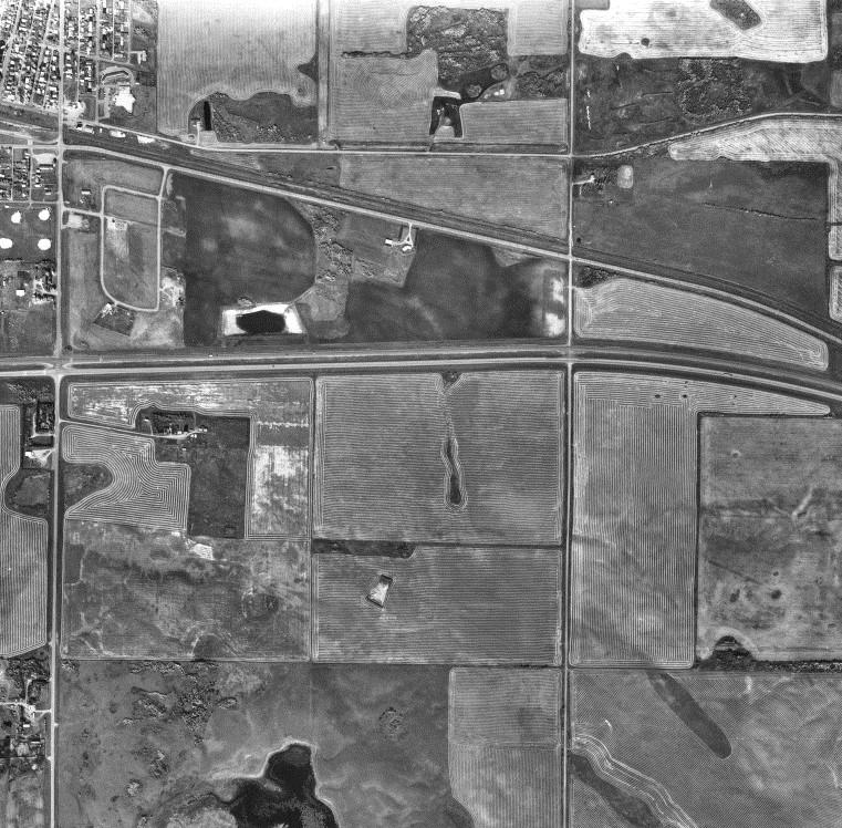
DESCRIPTION
PhotoDescription:1993AirPhoto
X-TerraFileNo.: 22148
LEGEND
ProposedProjectArea:
Railway: Highway:
REFERENCE
1993AER

Scale:1:17,100
CountyofMinburnNo.27
BiophysicalEnvironmental Assessment
FIGURE4
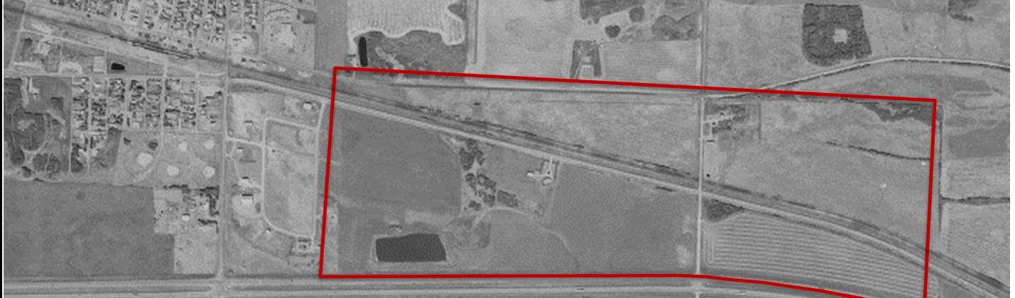
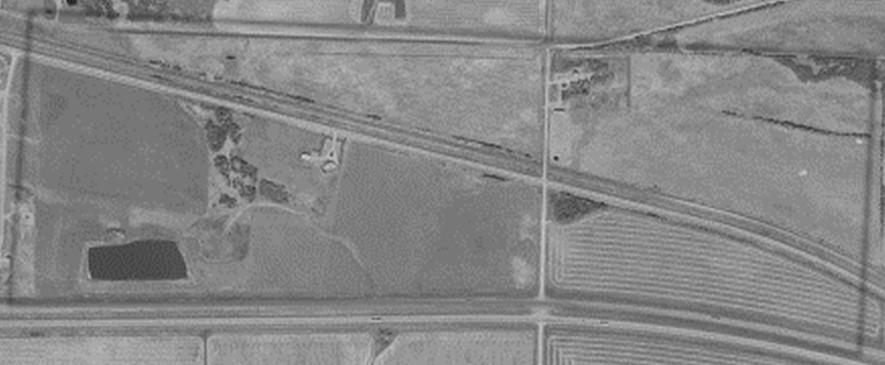
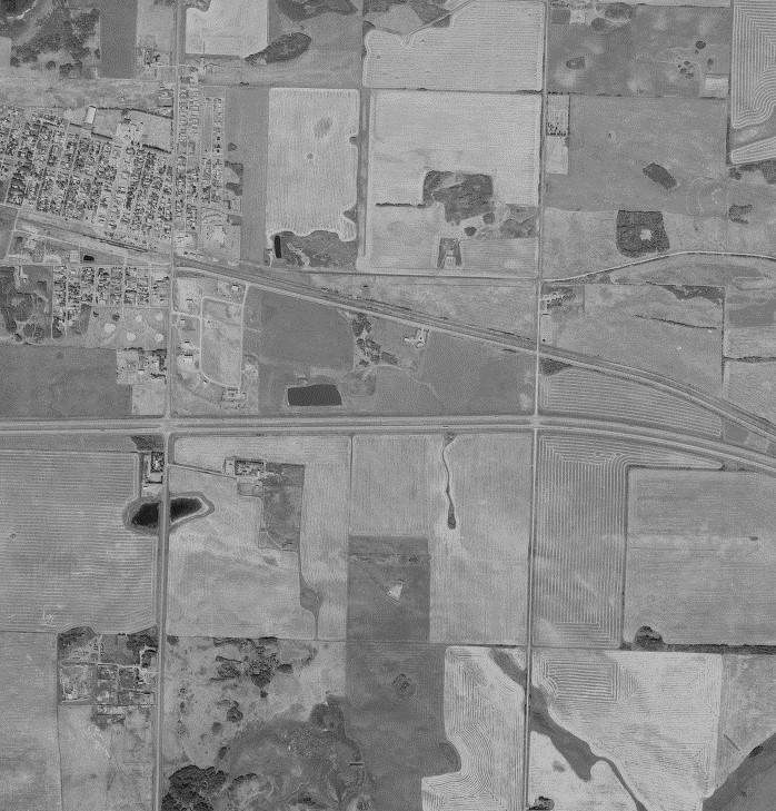
DESCRIPTION
PhotoDescription:1998AirPhoto
X-TerraFileNo.: 22148
LEGEND
ProposedProjectArea: Railway: Highway:
REFERENCE 1998AER

Scale:1:34,000
CountyofMinburnNo.27
BiophysicalEnvironmental Assessment
FIGURE5
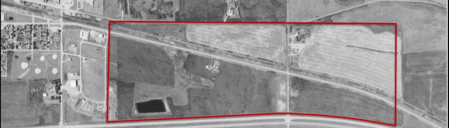
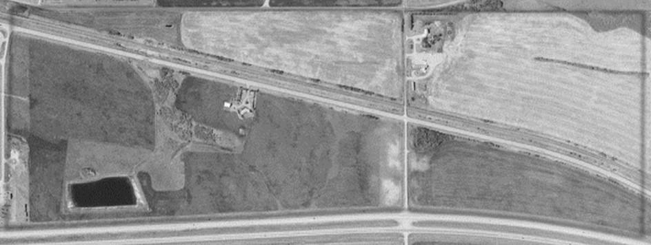
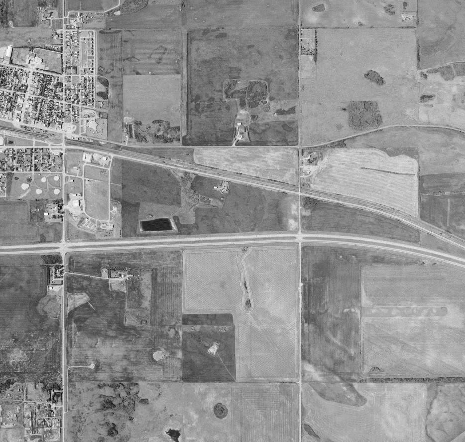
DESCRIPTION
PhotoDescription:2004AirPhoto
X-TerraFileNo.: 22148
LEGEND
ProposedProjectArea:
Railway: Highway:
REFERENCE
2004AER

Scale:1:17,000
CountyofMinburnNo.27
BiophysicalEnvironmental Assessment
FIGURE6
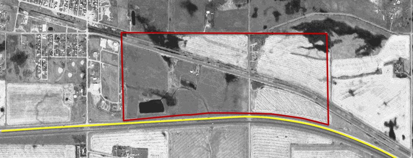
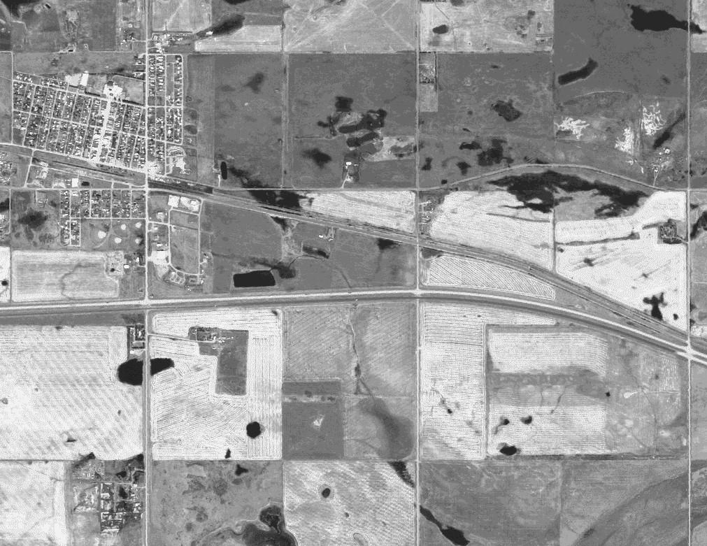
DESCRIPTION
PhotoDescription:2006AirPhoto
X-TerraFileNo.: 22148
LEGEND
ProposedProjectArea:
Railway: Highway:
REFERENCE
2006Abadata


Scale:1:33,000
CountyofMinburnNo.27
BiophysicalEnvironmental Assessment
FIGURE7
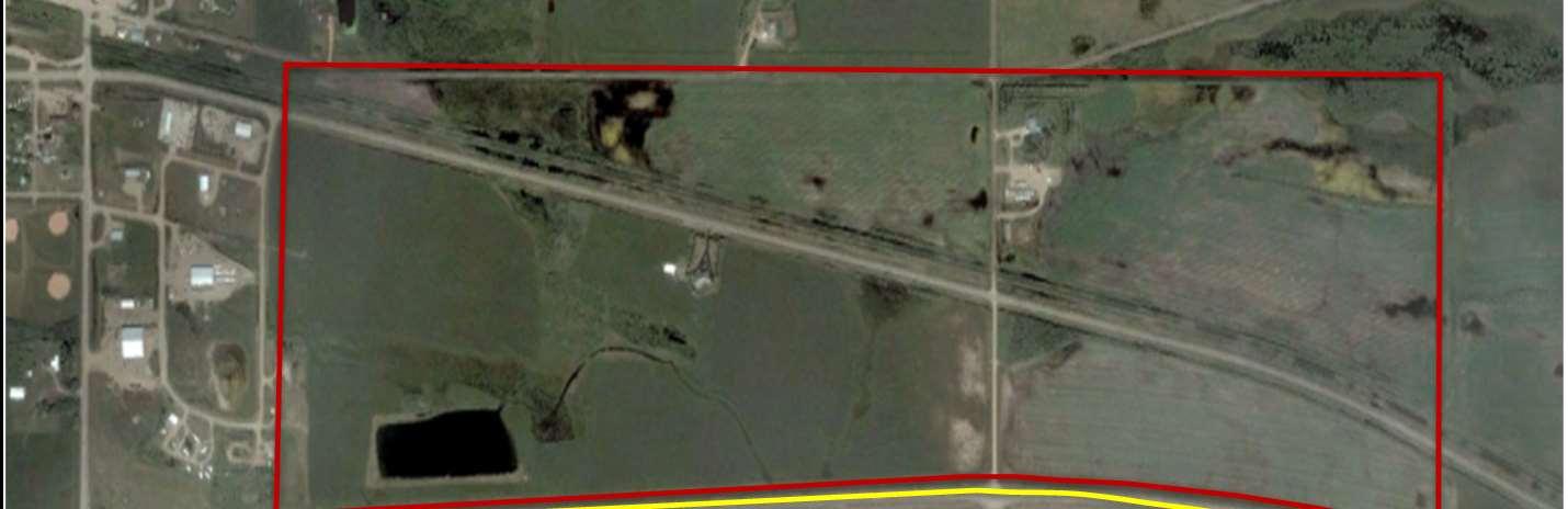
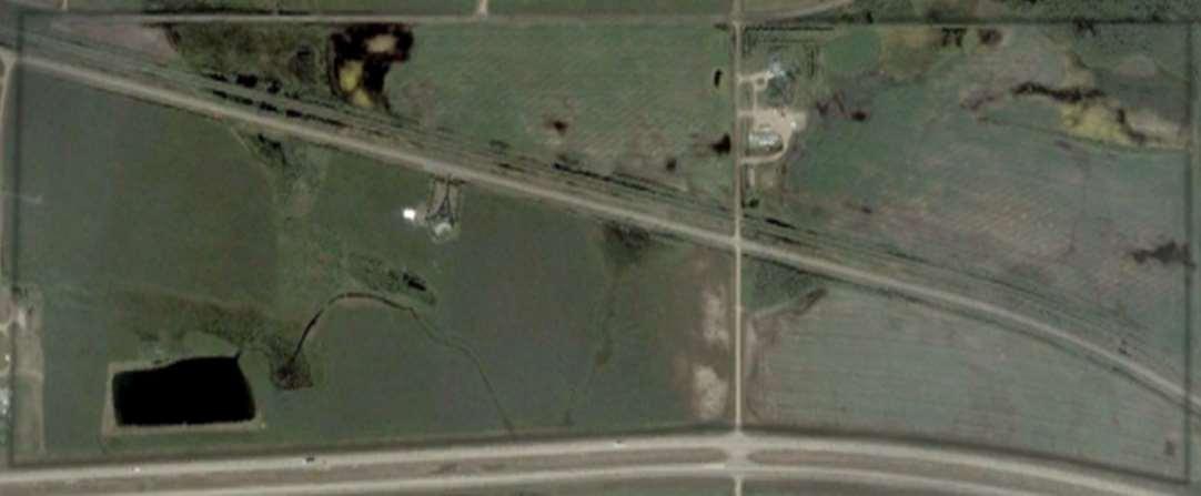
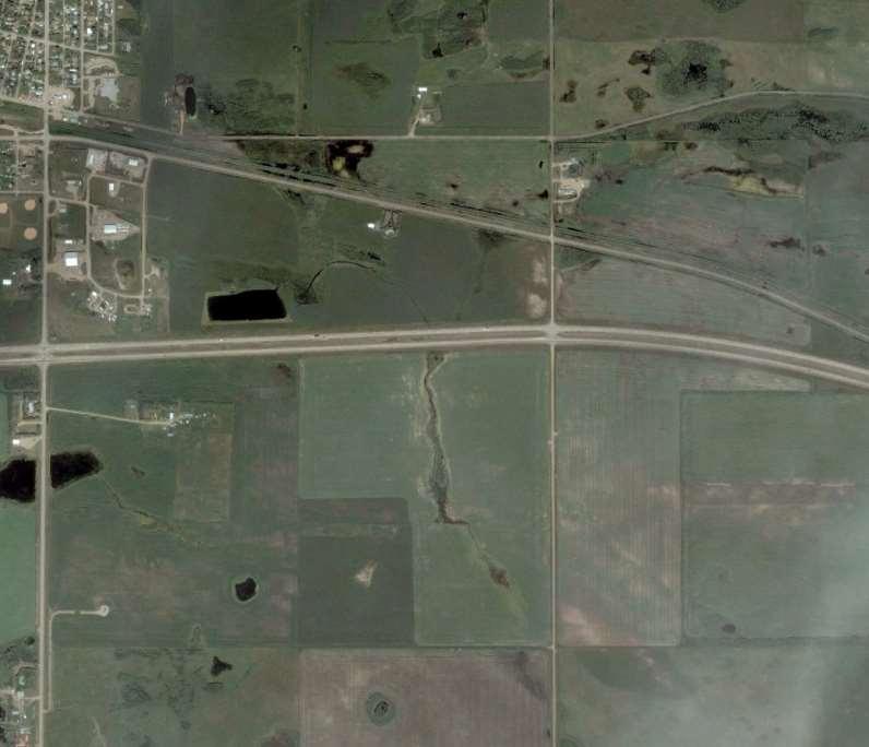
DESCRIPTION
PhotoDescription:2007AirPhoto
X-TerraFileNo.: 22148
LEGEND
ProposedProjectArea:
Railway: Highway:
REFERENCE
2007GoogleEarth


Scale:1:17,194
CountyofMinburnNo.27
BiophysicalEnvironmental Assessment
FIGURE8
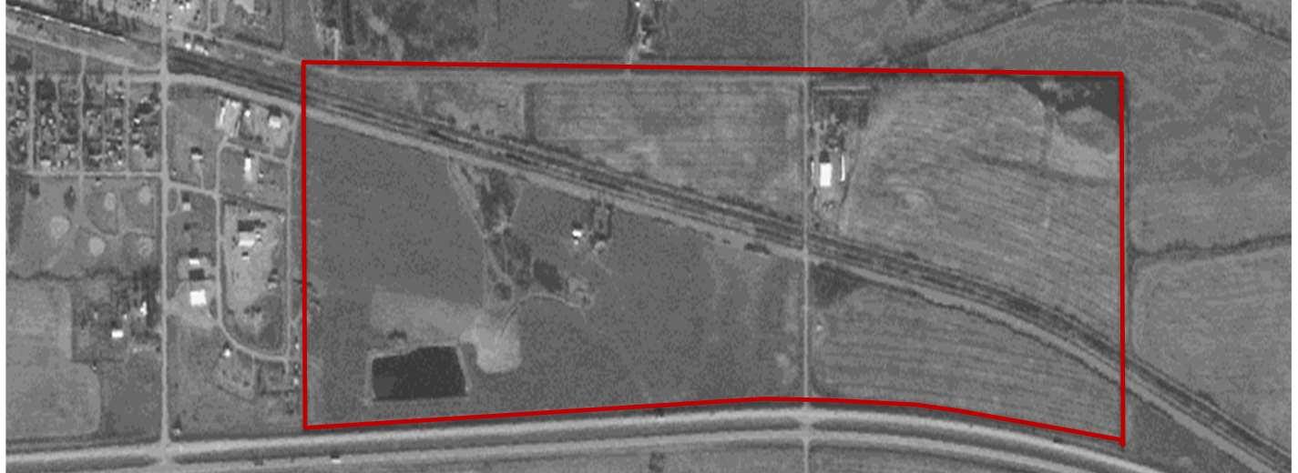
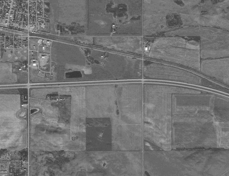
DESCRIPTION
PhotoDescription:2009AirPhoto
X-TerraFileNo.: 22148
LEGEND
ProposedProjectArea:
Railway: Highway:
REFERENCE
2009Abadata


Scale:1:17,194
CountyofMinburnNo.27
BiophysicalEnvironmental Assessment
FIGURE9
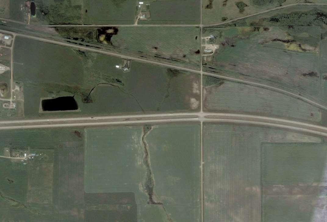
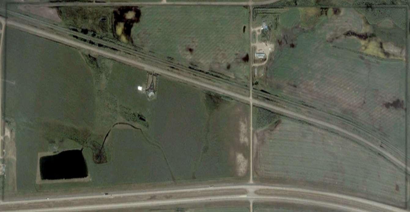
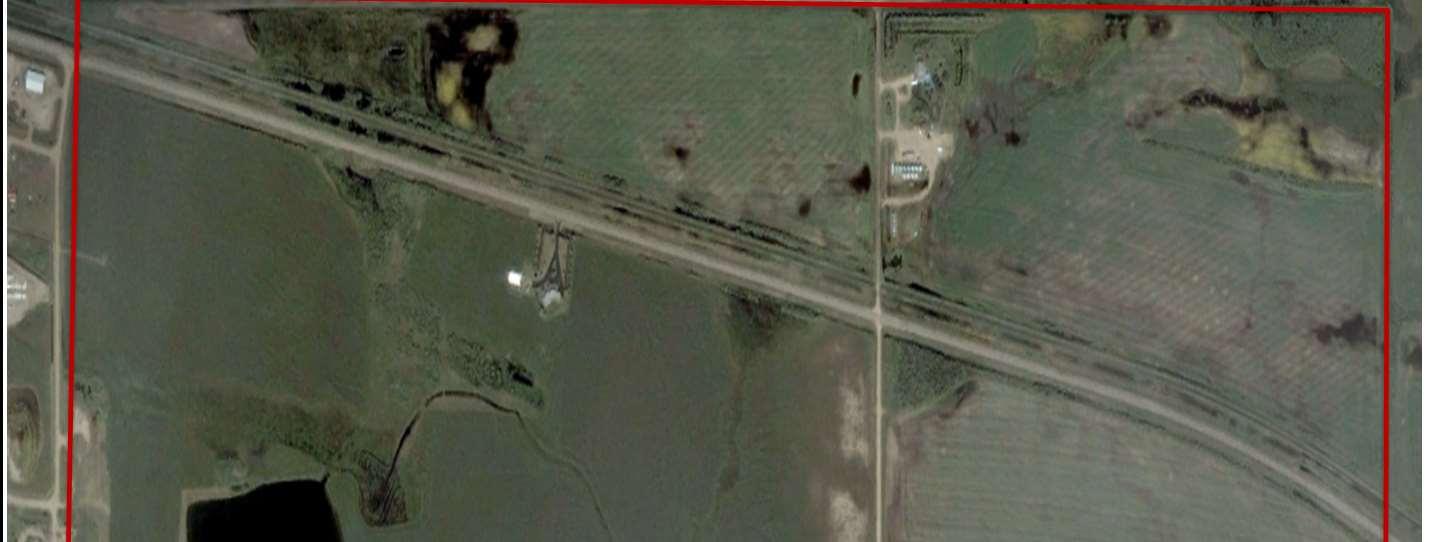
DESCRIPTION
PhotoDescription:2011AirPhoto
X-TerraFileNo.: 22148
LEGEND
ProposedProjectArea:
Railway: Highway:
REFERENCE
2011GoogleEarth
Scale:1:12,000
CountyofMinburnNo.27
BiophysicalEnvironmental Assessment
FIGURE10
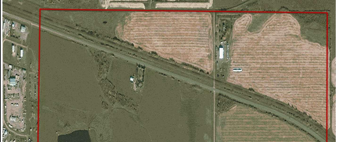
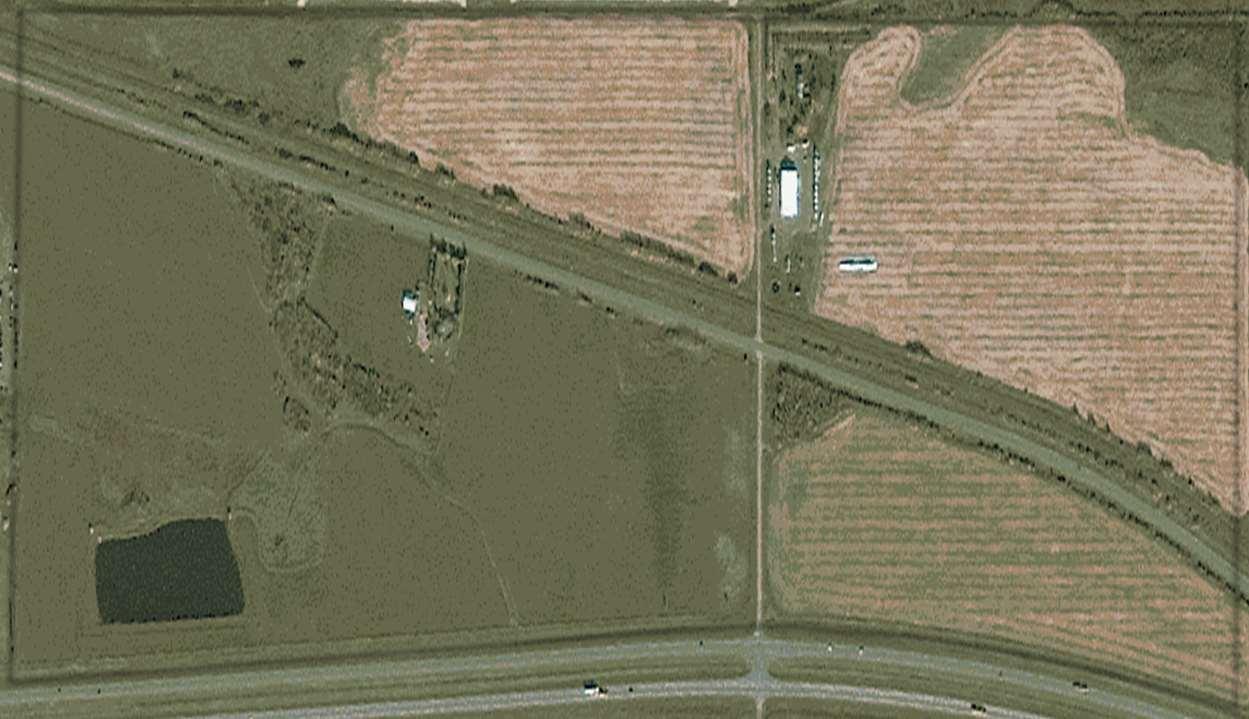
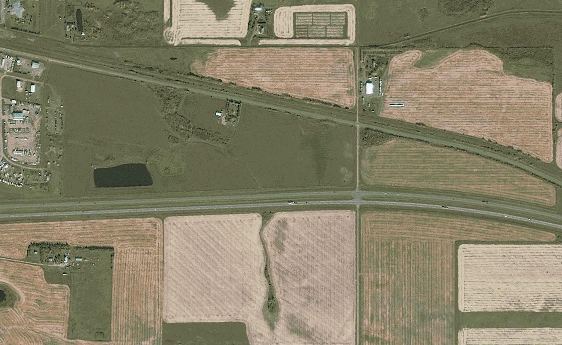
DESCRIPTION
PhotoDescription:2013AirPhoto
X-TerraFileNo.: 22148
LEGEND
ProposedProjectArea:
Railway: Highway:
REFERENCE
2013Abadata


Scale:1:16,042
CountyofMinburnNo.27
BiophysicalEnvironmental Assessment
FIGURE11
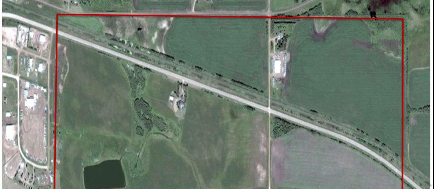
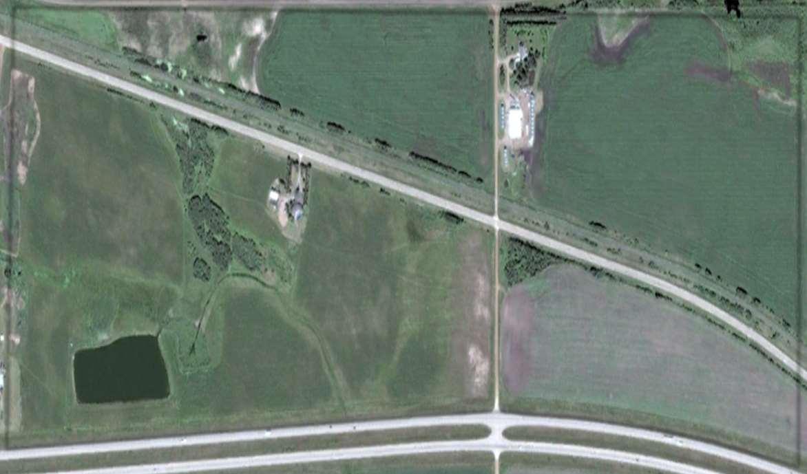
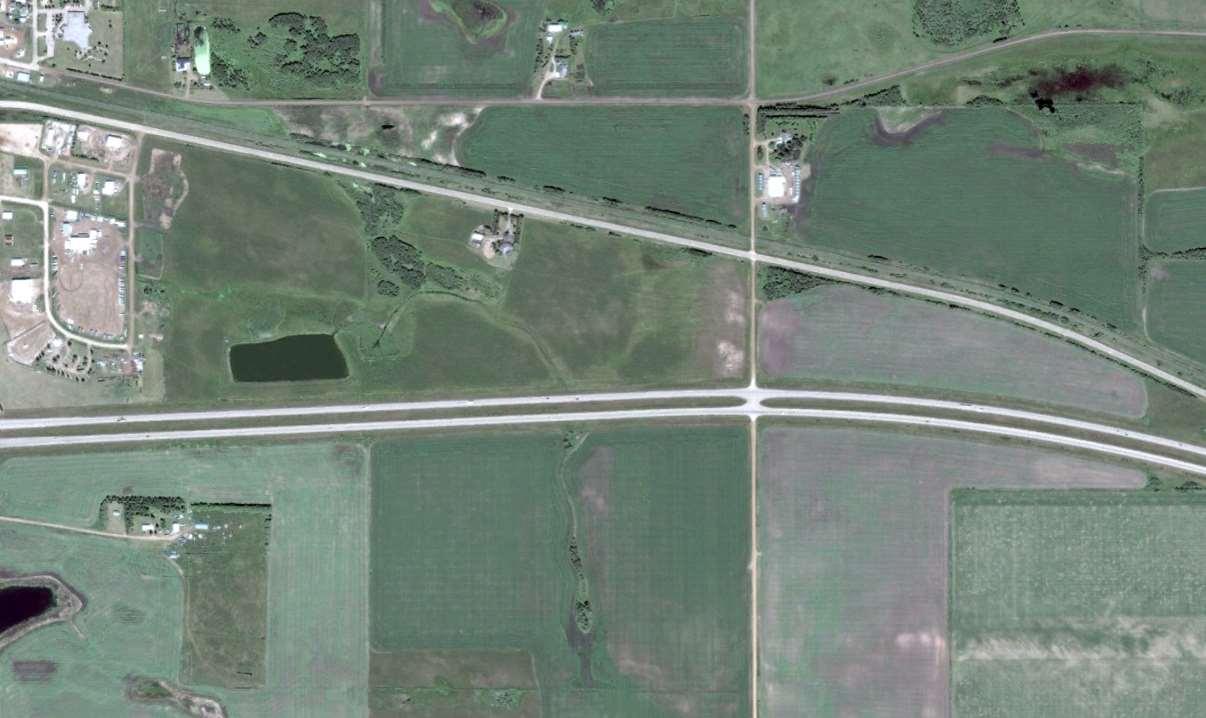
DESCRIPTION
PhotoDescription:2016AirPhoto
X-TerraFileNo.: 22148
LEGEND
ProposedProjectArea:
Railway: Highway:
REFERENCE
2016GoogleEarth
Scale:1:16,000
CountyofMinburnNo.27
BiophysicalEnvironmental Assessment
FIGURE12
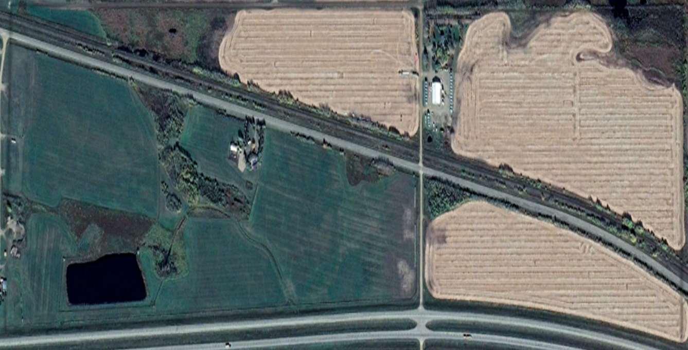
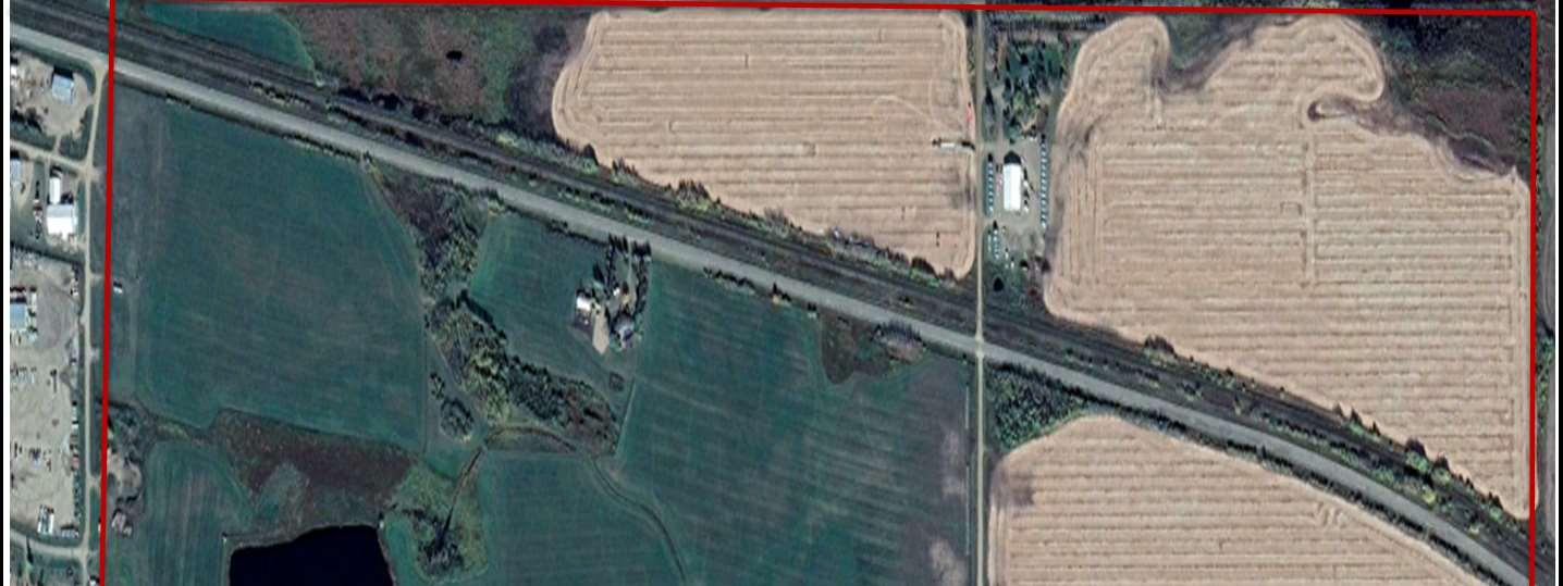
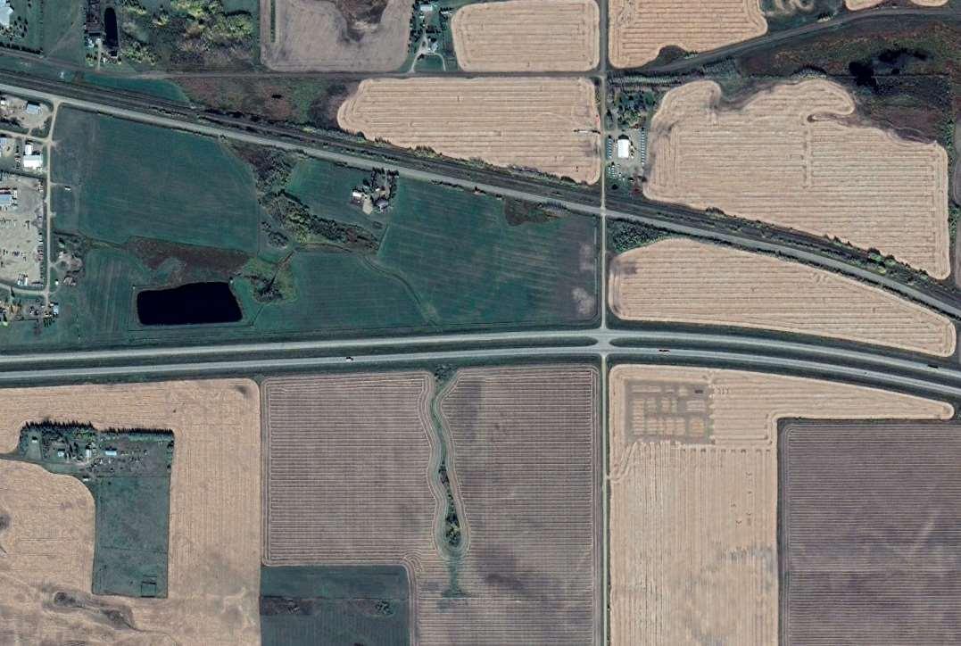
DESCRIPTION
PhotoDescription:2019AirPhoto
X-TerraFileNo.: 22148
LEGEND
ProposedProjectArea:
Railway: Highway:
REFERENCE
2019GoogleEarth

Scale:1:12,032
CountyofMinburnNo.27
BiophysicalEnvironmental Assessment
FIGURE13
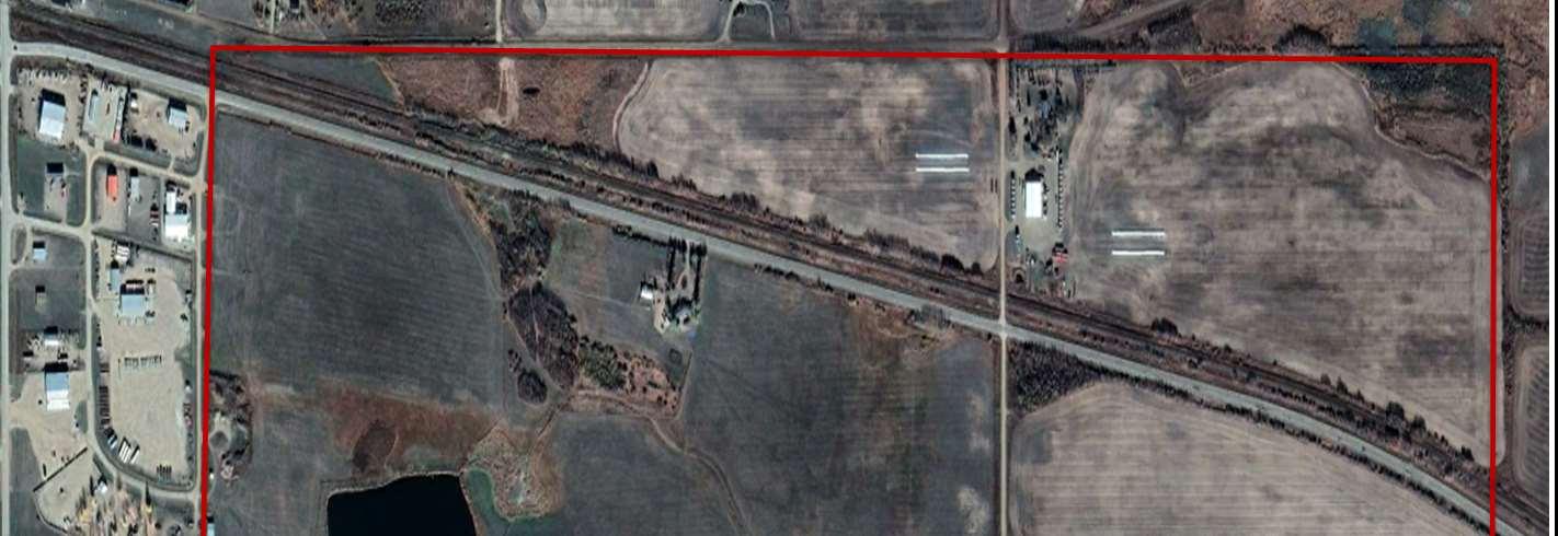
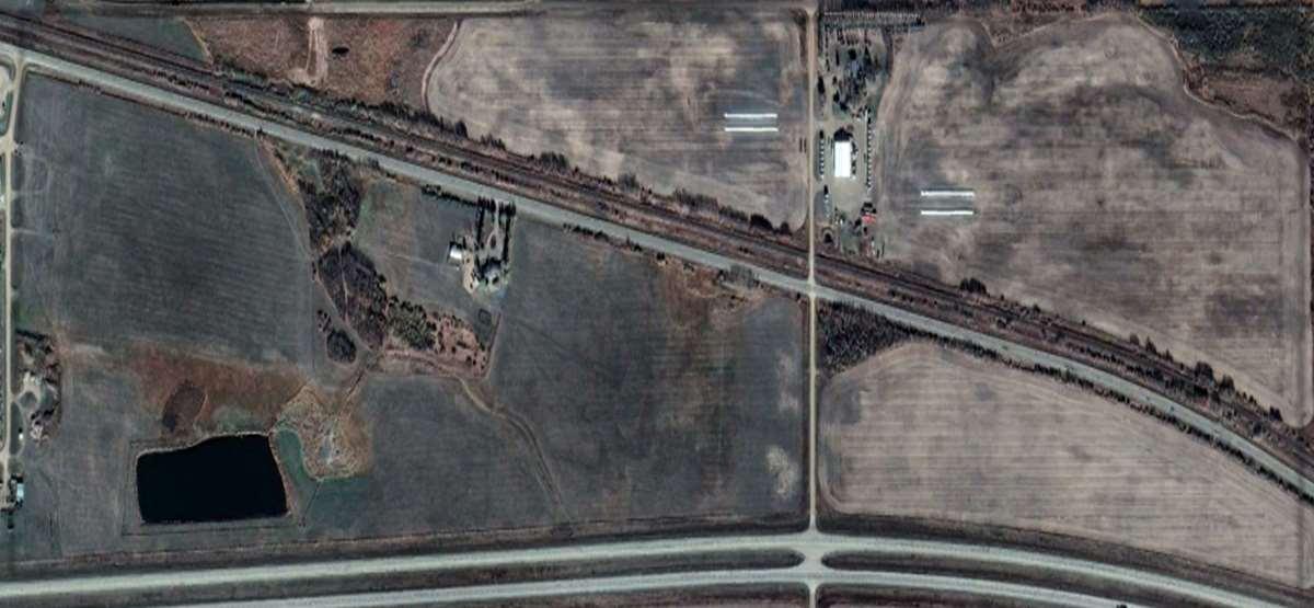
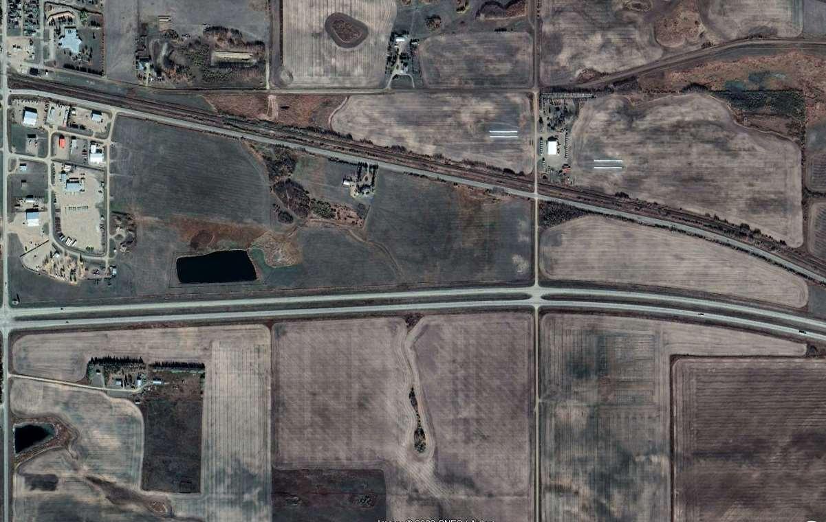
DESCRIPTION
PhotoDescription:2021AirPhoto
X-TerraFileNo.: 22148
LEGEND
ProposedProjectArea:
Railway: Highway:
REFERENCE
2021GoogleEarth


Scale:1:16,050
CountyofMinburnNo.27
BiophysicalEnvironmental Assessment
FIGURE14
D:
A THUNDERCHILD ENERGY SERVICES COMPANY Biophysical Desktop Assessment Project #: 22148 Client: County of Minburn No. 27 Creation Date: August 5, 2022 D
TITLES
APPENDIX
LAT REPORT/ACIMS/FWMIS/HRIA REPORTS/LAND
Landscape Analysis Tool (LAT) Report
LAT Number: 000005E2C8
Project Name:
Project Description:
LAT Date: 2022-08-01
ASP Lands 19 and 20-50-8 W4M
Disposition Type: DML
Purpose Type: PURL
Activity Type: PURL07DMLP
Responsibility of Applicants:
Miscellaneous Lease
Public Works
Other Facility
Miscellaneous Lease
000005E2C8
Page 1 of 14
19:03:28
It is the applicant s responsibility to conduct a full review of the generated LAT Report, ensuring that you are aware and have a full understanding of the identified standards and conditions, and any additional limitations that may also be imposed by an approved higher level plan, reservation or notation or any other law or Order of the Province or the Government of Canada that may impact the placement, construction or operation of the proposed disposition, purpose and activity.
The applicant must assess if the proposed disposition, purpose and activity can meet the applicable standards, conditions and any limitations which will subsequently determine if the application can be submitted to the regulatory body. Applicants should complete a thorough review of regulatory and application processes including supporting procedural documents and the generated LAT Reports prior to making this determination.
Where the applicant chooses not to meet, or is not able to meet, one or more Approval Standards or higher level plans within the generated LAT Report as submitted as part of the application, or any affected reservations as identified within the land status report, the applicant is required to complete the appropriate mitigation as part of their supplement submission that addresses individually each of the items not being met.
The information provided within the LAT Tool is a spatial representation of features provided to the applicant for activity and land use planning. The accuracy of these layers varies depending on the resource value being represented. The regulatory body insists that site visits, wildlife surveys and groundtruthing efforts are completed to ensure that you, the applicant can meet the procedures detailed within the PreApplication Requirements for Formal Dispositions, the identified approval standards, operating conditions and Best Management Practices as represented within the Master Schedule of Standards and Conditions
Proximity to Watercourse/Waterbodies:
Applicants will ensure that standards or conditions for Watercourse/Waterbody features as identified within the generated LAT Report are followed. It is the responsibility of the applicant to ensure the identified setbacks and buffers are properly established through a pre-site assessment and maintained.
NOTE: Be aware that the submission of a LAT Report as part of an application submission does not imply approval of the activity. The standards and conditions identified within the LAT Report may be subject to change based on regulatory review.
Landscape Analysis Tool (LAT) Report
Base Features
Green/White Area
Municipality
White Area
County of Minburn No. 27
Miscellaneous Lease
000005E2C8
Page 2 of 14
Provincial Grazing Reserve
Rocky Mountain Forest Reserve
PLUZ Areas
Protected Areas
Provincial Sanctuaries
Wildlife Corridors
Restricted Area
Game Bird Zone 3
Seasonal
FMA FMU
Landscape Analysis Tool (LAT) Report
Higher Level Plans
Integrated Resource Plan (Local)
Integrated Resource Plan (Subregional)
Access Management Plan
Landscape Management Plan
Page 3 of 14
Miscellaneous Lease 000005E2C8
Landscape Analysis Tool (LAT) Report
Additional Application Requirements
Wildlife Survey
Historical Resources
HRV Rating Category
Historic Resources Application Required: No
Yes DND Area
Page 4 of 14
While no specific historic resource concerns have been identified within the proposed activity area, Section 31 of the Historical Resources Act states that a person who discovers a historic resource in the course of making an excavation for a purpose other than for the purpose of seeking historic resources shall forthwith notify the Minister of the discovery. Should a historic resource be encountered with the construction or operation of this disposition, information on who to contact can be found on the Ministry of Culture and Tourism s website in; Standard Requirements under the Historical Resources Act: Reporting the Discovery of Historic Resources.
Miscellaneous Lease 000005E2C8
Landscape Analysis Tool (LAT) Report
Miscellaneous Lease
000005E2C8
Page 5 of 14
Sensitive Features
Wildlife and Other Sensitive Species
Burrowing Owl Range
Caribou Range
Caribou Range - Zone A
Caribou Range - Zone B
Colonial Nesting Birds
Critical Habitat of Aquatic Species at Risk
Endangered and Threatened Plants Ranges
Greater Short-horned Lizard Habitat
Greater Short-horned Lizard Range
Greater Sage Grouse Core Area
Greater Sage Grouse Recovery Area
Greater Sage Grouse Leks and Buffer
Grizzly Bear Zone
High Risk Watersheds
Key Wildlife and Biodiversity Areas
Mountain Goat and Sheep Zone
Federal Orders:
Greater Sage Grouse
Grassland and Natural Regions:
Central Parkland Yes
Central Parkland and Northern Fescue
Chinook Grasslands
Dry Mixed Grass
Foothills Fescue
Foothills Parkland Grasslands
Grassland and Parkland Natural Region Yes
Mountain Goat and Sheep Areas
Disease Buffer
Ord's Kangaroo Rat Range
Ord's Kangaroo Rat Key Habitat Area
Piping Plover Waterbodies
Provincial Hibernacula Buffer
Sensitive Amphibian Ranges
Sensitive Raptor Range
Sensitive Snake Habitat
Sensitive Snake Hibernacula Range
Sharp-tailed Grouse Leks and Buffer
Sharp-tailed Grouse Survey Yes
Special Access Area
Swift Fox Range
Trumpeter Swan
Waterbodies/Watercourse
Trumpeter Swan Watercourse Buffer
Mixed Grass Sub-region layer
Montane
Northern Fescue
Peace River Parkland
Permafrost
Rough Fescue PNT
Subalpine or Alpine
Intersected
Intersected
Intersected
Intersected
Intersected
Landscape Analysis Tool (LAT) Report
Alberta Township System (ATS) Land List
Page 6 of 14
Grassland and Parkland Natural Region,Sharp-tailed Grouse Survey,Central Parkland,Green / White Area NE
Grassland and Parkland Natural Region,Sharp-tailed Grouse Survey,Central Parkland,Green / White Area
Grassland and Parkland Natural Region,Sharp-tailed Grouse Survey,Central Parkland,Green / White Area
NW
Grassland and Parkland Natural Region,Sharp-tailed Grouse Survey,Central Parkland,Green / White Area NE
Grassland and Parkland Natural Region,Sharp-tailed Grouse Survey,Central Parkland,Green / White Area
Quarter Section Township Range Meridian Road Allow. Sensitive Features Identified
50 8 4 RW
NW 20
50 8 4
19
4
NW 19 50 8
20 50 8 4
50 8 4
20
Miscellaneous
000005E2C8
Lease
Landscape Analysis Tool (LAT) Report
Page 7 of 14
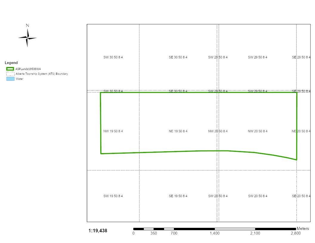
Miscellaneous Lease 000005E2C8
Landscape Analysis Tool (LAT) Report
Land Management
Report
Miscellaneous Lease
000005E2C8
Page 8 of 14
1 1030-AS Where an Integrated Resource Plan or a Reservation/Protective Notation identifies a greater set back, the greater set back will prevail.
2 1031-AS Where a Higher Level Plan* exists, the Disposition Holder must follow any direction provided within that plan.
3 1033-AS With the exception of pipelines, for activities that fall within any Protective Notation (PNT) lands with a purpose code 400 Series encompassing a section of land (259 hectares) or less, located in the Provincial White Area, the Disposition Holder must construct all activities within lands previously disturbed or cleared. Where no previous disturbance exists, activities must occur within 100 metres of the PNT.
4 1041 The Disposition Holder must maintain proper drainage of surface water.
5 1044-AS The Disposition Holder must not locate activities within 45 metres from the top of any coulees* with the exception of activities such as; access, pipelines and linear easements crossing those features.
6 1049 The Disposition Holder must remove all garbage and waste material from this site.
7 1053 The Disposition Holder must not enter the boundaries of any research or sample plot unless consent is received from the reservation holder.
8 1061 Where FireSmart activities are considered, the Disposition Holder must follow Information Letter- Authorization of FireSmart Activities on Public Land as amended from time to time.
Vegetation
9 1300 The disposition holder must manage all regulated weeds to the satisfaction of the regulatory body.
10 1302 "The Disposition Holder must remove all deciduous or coniferous merchantable timber from the Activity as per the following utilization standards;
- Deciduous Timber: 15 cm Base/10 cm Top
- Coniferous Timber: 15 cm Base/11cm Top and haul said timber to the location of end use."
11 1304 For fire control purposes on forested lands, the Disposition Holder must dispose of excess coarse woody debris* not utilized for rollback* or stockpiled for reclamation*.
12 1305 Within FireSmart Community Zones*, the Disposition Holder must dispose of coarse woody debris* by burning unless a Debris Management Plan has been approved under the Forest and Prairie Protection Act.
ID Approval Condition
Report ID Approval Condition
Landscape Analysis Tool (LAT) Report
Miscellaneous Lease
000005E2C8
Page 9 of 14
13 1356 The Disposition Holder must not conduct the Activity during adverse ground conditions*.
14 1357 The Disposition Holder must prevent erosion* and sedimentation on to adjacent* Lands or Water bodies * that results from the activity.
15 1359-AS The Disposition Holder must not remove from the Lands topsoil* or subsoil* unless approved in writing by the Regulatory Body.
16 1360 "Where activities have occurred on the Lands that do not involve minimal disturbance* construction, the Disposition Holder must salvage topsoil* for land reclamation as follows:
a. Salvage all topsoil* from:
i. Mineral soils
ii. Shallow organic soils*
iii. Reclaimed soils
b. Where the depth of the topsoil* is less than 15 cm, the topsoil* and part of the subsoil* to a total depth of 15 centimetres must be salvaged, unless the upper subsoil* is considered chemically unsuitable*."
17 1363 All reclamation material* must be considered suitable as defined in the May 2001 Salt Contamination Assessment Guidelines and meet the February 2016 Alberta Tier 1 Soil and Groundwater Remediation Guidelines, as amended or replaced from time to time.
18 1365 "The Disposition Holder must store reclamation material* in accordance with all of the following:
a. reclamation material* must not be placed beneath the ground surface or buried in any way;
b. coarse woody debris* stored for reclamation purposes for greater than 12 months must be mixed with topsoil*; and c. topsoil* and subsoil* must be stored separately."
19 1367 The Disposition Holder must not mix wood chips with any reclamation material*.
20 1368 The Disposition Holder must not apply wood chips to the lands at a depth greater than five (5) centimeters.
21 1369 The Disposition Holder must manage wood chips in accordance with the directive ID 2009-01 Management of Wood Chips on Public Land as amended from time to time.
22 1370 The Disposition Holder must not store piles or windrows of reclamation material* within standing timber.
23 1371 The Disposition Holder must not use soil sterilant on the Lands.
Report ID Approval Condition
Soil
Landscape Analysis Tool (LAT) Report
Watercourse / Waterbody
Report ID
Miscellaneous Lease
000005E2C8
Page 10 of 14
24 1402-AS The Disposition Holder must not conduct the Activity within the following watercourse* setbacks from the top of the breaks:
a. Intermittent watercourses* including springs must have a setback of at least 45 metres.
b. Small Permanent watercourses* must have a setback of at least 45 metres.
c. Large Permanent watercourses* must have a setback of at least 100 metres.
25 1412 The Disposition Holder must acquire an authorization for access (offdisposition) for water withdrawal activities.
26 1419 For use of equipment within the bed of a water body*, the Disposition Holder must prior to operations follow the Decontamination Protocol for Work in or Near Water as amended from time to time.
27 1420 The Disposition Holder must provide a completed Record of Decontamination form as proof of decontamination to the Regulatory Body upon request.
Reclamation
Report ID Approval Condition
28 1451 For progressive reclamation* on forested lands*, the Disposition Holder must replace all reclamation materials* that have been salvaged in accordance with all of the following:
a. all salvaged subsoil* must be replaced, then all salvaged topsoil*; and b. reclamation materials* must be replaced over the entire progressive reclamation area*; unless otherwise approved in writing by the Regulatory Body.
29 1453 The Disposition Holder must complete temporary reclamation* on the Lands within 1 growing season of construction phase* for all topsoil* and subsoil* stockpiles required for final reclamation*.
30 1454 The Disposition Holder must prior to seeding herbaceous seed in forested* or peatlands* submit a Request for Seeding in writing to the Regulatory Body that contains all of the following:
a. rationale for conducting seeding of herbaceous species*;
b. a description of the proposed site for seeding including information with respect to the following:
i. whether the Lands are subject to high erosion* and;
ii. whether the Lands are prone to invasion from agronomic or weed species.
c. a proposed seed mix composition for re-vegetation of the Lands in accordance with the Native Plant Revegetation Guidelines for Alberta, 2001 as amended or replaced from time to time or a rationale for alternate species;
d. provide a seed certificate in accordance with the Seed Act for the seed mixed mix to be used for re-vegetation* and; any other information requested by the Regulatory Body.
Approval
Condition
Landscape Analysis Tool (LAT) Report
Miscellaneous
Page 11 of 14
31 1455 The Disposition Holder must only conduct seeding in accordance with the written authorization of the Regulatory Body.
32 1456 The Disposition Holder must when seeding cultivated lands*;
a. use agronomic or forage seed that meets or exceeds Certified #1 as outlined in the Seeds Act and Seeds Regulations;
b. use seed mixes that are free of species listed in the Weed Control Act and;
c. provide a seed certificate to the Regulatory Body within 30 days of request.
33 1457 Within the Green Area* of the Province, the Disposition Holder must revegetate the Lands with trees or shrubs that meet the requirements of the December 2016 Alberta Forest Genetic Resource Management and Conservation Standards document, as amended or replaced from time to time.
34 1459 The Disposition Holder must not have slash and rollback* accumulations within five (5) metres of the perimeter of the disposition boundary, greater than the percent ground cover on the surrounding undisturbed forest floor.
35 1461 The Disposition Holder must complete progressive reclamation* on forested lands* for all associated and incidental disturbances to the Disposition.
36 1462 The following activities are excluded from progressive reclamation* requirement on forested lands*:
a) Lands that have received authorization for clay pad construction; and
b) Lands with a 4:1 or steeper slopes where a cut and fill has been constructed to level the ground surface.
37 1463 For final reclamation*, the Disposition Holder must complete all of the following:
a. contour the disturbed land to the pre-disturbance landform or to the landform approved by the Regulatory body;
b. replace all stockpiled subsoil*, then replace all stockpiled topsoil*;
c. spread all coarse woody debris* on forested lands* and;
d. reclamation materials* must be replaced over the entire area from which they were removed unless otherwise approved in writing by the Regulatory Body.
38 1464 The Disposition Holder must reclaim the Lands to the pre-disturbance land use type* unless otherwise authorized in writing by the Regulatory Body.
39 1600 The Disposition Holder must conduct a complete and immediate Wildlife Sweep* of the Lands subject to the disposition prior to any activity, as per the Wildlife Sweep Protocol
40 1601 The Disposition Holder must submit observations from a Wildlife Sweep* to the Fisheries and Wildlife Management Information System (FWMIS) and notify the issuing Regulatory Body in writing upon request that the Wildlife Sweep* was completed.
Wildlife Report ID Approval Condition
Lease
000005E2C8
Landscape Analysis Tool (LAT) Report
Miscellaneous Lease
000005E2C8
Page 12 of 14
41 1602-AS The Disposition Holder must incorporate a buffer* zone of a minimum width of 100m undisturbed vegetation, where an established buffer* does not already exist for any and all key habitat features including, but not limited to leks*, nests, dens and houses identified in the Wildlife Sweep*.
42 1603 When Wildlife Surveys* are required, the Disposition Holder must submit results as defined by the sensitive species inventory guidelines from Wildlife Survey* to the Fisheries and Wildlife Management Information System (FWMIS).
43 1608 The Disposition Holder must incorporate buffers*, setbacks and activity timing restrictions for any and all key habitat features including, but not limited to leks*, nests, dens and houses identified in the wildlife survey*.
44 1611-AS The Disposition Holder must conduct appropriate pre-construction wildlife* surveys as per the direction of the Sensitive Species Inventory Guidelines as amended from time to time where you intersect any of the following sensitive species;
- Sensitive Raptor Range
- Burrowing Owl Range
- Sensitive Snake Hibernacula Range
- Sharp-tailed Grouse Survey
- Swift Fox Range
- Ords Kangaroo Rat Range
- Piping Plover Waterbodies
- Endangered and Threatened Plant Ranges
- Grassland and Parkland Natural Regions (Grassland Bird Surveys)
Sharp-Tailed Grouse Survey / Leks and Buffers
Report ID Approval Condition
45 1740-AS
The Disposition Holder must not conduct any activities* within 500 metres of the perimeter of any known or identified active sharp-tailed grouse lek* sites.
Other Sensitive and Endangered Species
Report ID Approval Condition
46 1880-AS
Between April 15 and August 15, the Disposition Holder must not conduct any activities* within 100 metres of an active nest site for Federally listed species.
Grassland and Parkland Natural Region
Report ID Approval Condition
47 2054 On native grasslands*, the Disposition Holder must not crimp straw* subject to the following exceptions:
a) The straw* used for crimping must be sourced from a native species* from the same ecological range site* as the Lands;
b) The weed analysis for the straw* used for crimping must comply with the Weed Control Act, as amended or replaced from time to time.
Landscape Analysis Tool (LAT) Report
Miscellaneous Lease
000005E2C8
Page 13 of 14
48 2062 For activities that fall within native grasslands* as identified by the Central Parkland Subregion that requires Assisted Natural Recovery*, the Disposition Holder must submit a request for Assisted Natural Recovery in writing to the Regulatory Body that contains all of the following:
1. Rationale for conducting Assisted Natural Recovery*;
2. A description of the proposed site for Assisted Natural Recovery* including information with respect to the following:
a. whether the Lands are subject to high erosion;
b. whether the soil on the Lands has been disturbed to an area greater than 50m2;
c. whether the Lands are prone to invasion from agronomic or weed species;
3. A proposed seed mix composition for re-vegetation of the Lands:
a. that is consistent with native plant communities that are adjacent to and in the immediate vicinity of the Lands as determined by the A Preliminary Classification of Plant Communities in the Central Parkland Natural Subregion of Alberta, as amended or replaced from time to time;
b. provide a seed certificate in accordance with the Seed Act for the seed mix to be used for Assisted Natural Recovery* and;
c. any other information requested by the Regulatory Body.
49 2068 The Disposition Holder must not construct activities on native grassland* within the Grassland and Parkland Natural Region between April 15th and August 15th, unless grassland bird surveys are completed as per the Sensitive Species Inventory Guidelines Protocol as amended.
50 2069 The Disposition Holder must not conduct any activities within 100 metres of an active nest site between April 15th and August 15th for the following species: short-eared owl mountain plover long-billed curlew upland sandpiper Sprague s pipit
Chestnut-collared longspur
Loggerhead Shrike Bank Swallow
51 2070-AS On native grasslands* identified in the Central Parkland and Northern Fescue layer, the Disposition Holder must conduct a conservation assessment as outlined in Conservation Assessments in Native Grassland Strategic Siting and Pre-disturbance Site Assessment Methodology for Industrial Disturbances as amended or replaced from time to time. Upon request by the Regulatory Body, the Disposition Holder must submit the conservation assessment report in writing to the Regulatory Body within 30 days of the request.
Landscape Analysis Tool (LAT) Report
000005E2C8
Page 14 of 14
52 2071-AS The Disposition Holder must not conduct activities on loamy soils* in the Central Parkland and Northern Fescue layer as confirmed by the Disposition Holder through the required Conservation Assessment, subject to the following exceptions;
a) using existing disturbances* for activities; and b) locating activities adjacent* to existing occupied dispositions and nonnative vegetation areas.
Miscellaneous Lease
Date:16/6/2022
Requestor:Consultant
Reason for Request:EnvironmentalAssessment
SEC: 19 TWP: 050 RGE: 08 MER: 4
Non-sensitiveEOs(updated:October2017)

No Non-sensitive EOs Found: Next Steps - See FAQ (https://www.albertaparks.ca/albertaparksca/managementland-use/alberta-conservation-information-management-system-acims/faqs.aspx#2 - Process)
SensitiveEOs(updated:October2017)
No Sensitive EOs Found: Next Steps - See FAQ (https://www.albertaparks.ca/albertaparksca/management-landuse/alberta-conservation-information-management-system-acims/faqs.aspx#2 - Process)
Updated:Feb17,2022
M_RR_TTT_SS EO_ID ECODE S_RANK SNAME SCOMNAME LAST_OBS_D
M-RR-TTT EO_ID ECODE S_RANK SNAME SCOMNAME LAST_OBS_D
Date:16/6/2022
Requestor:Consultant
Reason for Request:EnvironmentalAssessment
SEC: 20 TWP: 050 RGE: 08 MER: 4
Non-sensitiveEOs(updated:October2017)
No Non-sensitive EOs Found: Next Steps - See FAQ (https://www.albertaparks.ca/albertaparksca/managementland-use/alberta-conservation-information-management-system-acims/faqs.aspx#2 - Process)
SensitiveEOs(updated:October2017)
No Sensitive EOs Found: Next Steps - See FAQ (https://www.albertaparks.ca/albertaparksca/management-landuse/alberta-conservation-information-management-system-acims/faqs.aspx#2 - Process)
Updated:Feb17,2022
M_RR_TTT_SS EO_ID ECODE S_RANK SNAME SCOMNAME LAST_OBS_D
M-RR-TTT EO_ID ECODE S_RANK SNAME SCOMNAME LAST_OBS_D

Fish and Wildlife Internet Mapping Tool (FWIMT)
(source database: Fish and Wildlife Management Information System (FWMIS))
Species Summary Report
Species present within the current extent Fish
Contact Information
For contact information, please visit: https://www.alberta.ca/fisheries-and-wildlife-management-contacts.aspx
Report Date: 16-Jun-2022 14:39
Inventory Wildlife Inventory Stocked Inventory No Species Found in Search Extent No Species Found in Search Extent No Species Found in Search Extent Buffer Extent Centroid (X,Y) Projection Centroid (Qtr Sec Twp Rng Mer) Radius or Dimensions 755758, 5913816 10-TM AEP Forest NE 19 50 8 4 3 kilometers
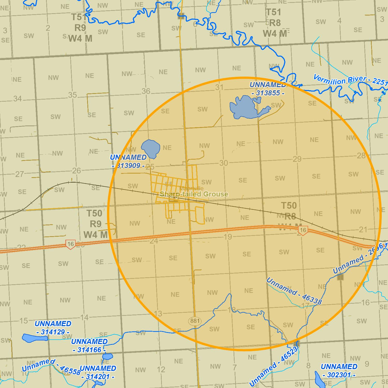
Display may contain: Base Map Data provided by the Government of Alberta under the Alberta Open Government Licence. Cadastral and Dispositions Data provided by Alberta Data Partnerships. (c)GeoEye, all rights reserved. Information as depicted is subject to change, therefore the Government of Alberta assumes no responsibility for discrepancies at time of use
© 2022 Government of Alberta
16-Jun-2022 14:39 Map Results
Fish and Wildlife Internet Mapping Tool (FWIMT)
(source database: Fish and Wildlife Management Information System (FWMIS))
Species Summary Report
Report Date: 16-Jun-2022 14:36
Contact Information
For contact information, please visit: https://www.alberta.ca/fisheries-and-wildlife-management-contacts.aspx
Inventory Wildlife Inventory Stocked Inventory No Species Found in Search Extent No Species Found in Search Extent No Species Found in Search Extent Buffer Extent Centroid (X,Y) Projection Centroid (Qtr Sec Twp Rng Mer) Radius or Dimensions 755768, 5913801 10-TM AEP Forest NE 19 50 8 4 2465, 812 meters
Species present within the current extent Fish
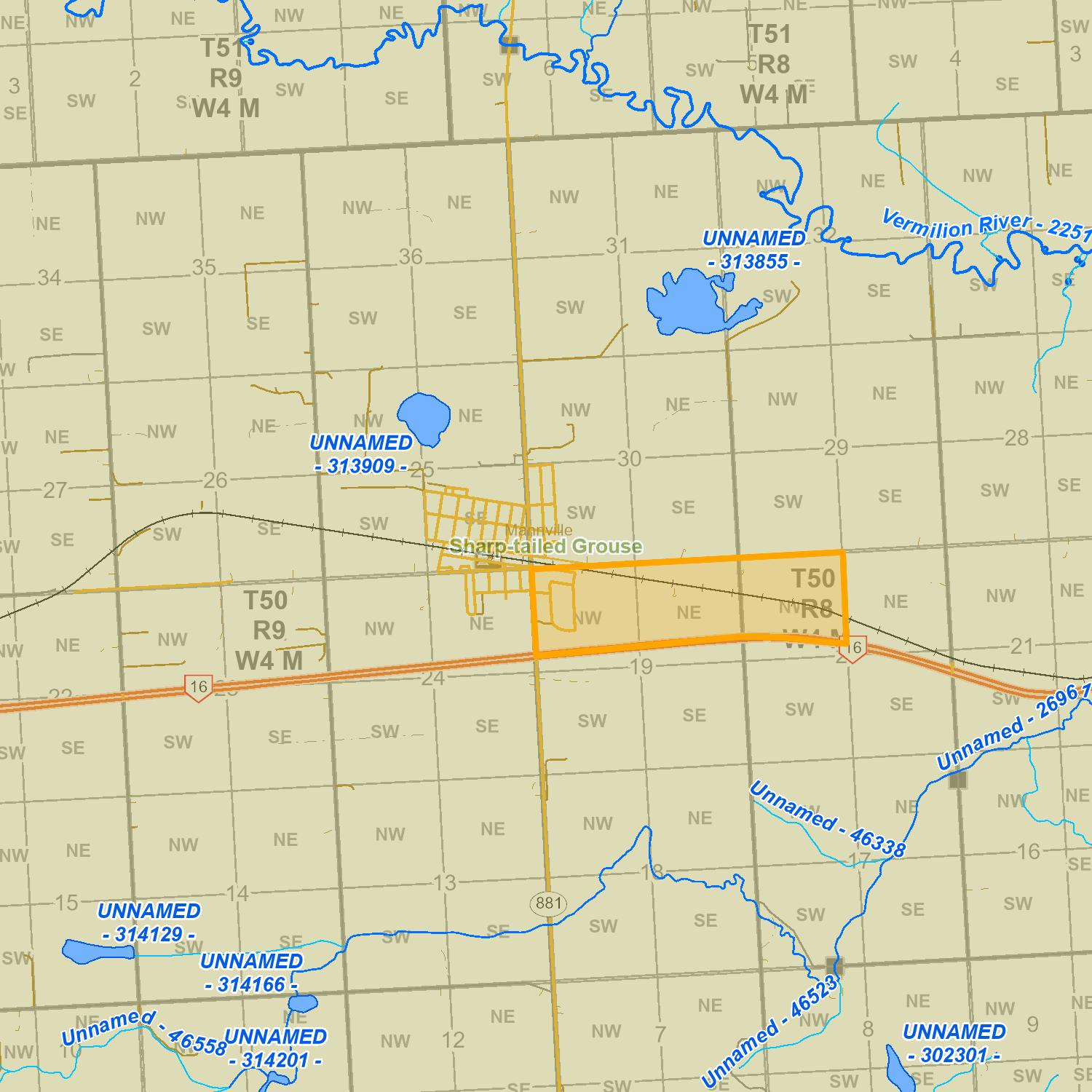
Display may contain: Base Map Data provided by the Government of Alberta under the Alberta Open Government Licence. Cadastral and Dispositions Data provided by Alberta Data Partnerships. (c)GeoEye, all rights reserved. Information as depicted is subject to change, therefore the Government of Alberta assumes no responsibility for discrepancies at time of use
© 2022 Government of Alberta
16-Jun-2022 14:36 Map Results
ListingofHistoricResources-HistoricResourceValues
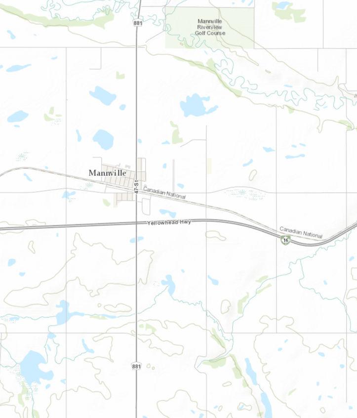
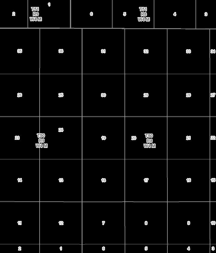
6/16/2022,2:21:06PM
ListingofHistoricResourcesPublic-HRV1
ATSTownshipIndexLabelAboveHydro
ATSSectionwithRoadAllowanceLabelBelowHydro
ATSTownshipIndexOutline5
ATSSectionwithRoadAllowanceOutline1
1h 5p 5p 5a,p 5a,p 5a 5p 5a 5a 5a,p 5a 5a 5a 5a 5a,p 5p 5p 5p 5p 5p 5a,p 5a,p
Copyright Government ofAlberta, ProvinceofAlberta, Esri Canada, Esri, HERE, Garmin, GeoTechnologies, Inc., USGS, METI/NASA, NGA, EPA, USDA,AAFC,NRCan
0 0.75 1.5 0.38 mi 0 1 2 0.5 km 1:72,224 ArcGISWebAppBuilder ActivitiesplannedforlandsnotincludedintheListingofHistoricResourcesmaystillrequireHistoricalResourcesActapproval. TheresultsofaListingsearchMUSTbeusedinconjunctionwiththe

S
LINC
0035 392 456
LAND TITLE CERTIFICATE
SHORT LEGAL
151 036 4;8;50;19;NW,NE
LEGAL DESCRIPTION
MERIDIAN 4 RANGE 8 TOWNSHIP 50
SECTION 19
ALL THAT PORTION OF THE NORTH HALF WHICH LIES NORTH EAST OF RAILWAY RIGHT OF WAY PLAN 3999R CONTAINING 16.08 HECTARES (39.74 ACRES) MORE OR LESS EXCEPTING THEREOUT: HECTARES (ACRES) MORE OR LESS A) PLAN 1223892 ROAD
0.55 (N.W. 1/4)
1.03 (N.E. 1/4)
EXCEPTING THEREOUT ALL MINES AND MINERALS AND THE RIGHT TO WORK THE SAME
ESTATE: FEE SIMPLE
MUNICIPALITY: COUNTY OF MINBURN NO. 27
REFERENCE NUMBER:122 322 418
OWNERS
MICHAEL BURY AND MELANIE BURY
BOTH OF: BOX 118 MANNVILLE ALBERTA T0B 2W0 AS JOINT TENANTS
TITLE NUMBER
132
0.222
0.415
CONSIDERATION DOCUMENT TYPE VALUE REGISTERED OWNER(S) 132 151 036 TRANSFER OF LAND $80,000 $80,000 REGISTRATION DATE(DMY) 28/05/2013
(
CONTINUED )
REGISTRATION NUMBER
DATE (D/M/Y) PARTICULARS
862 005 167
09/01/1986
UTILITY RIGHT OF WAY
862 005 168
09/01/1986
902 243 518
17/08/1990
TOTAL INSTRUMENTS:
003
2 PAGE # 132 151 036
GRANTEE - ALBERTA GOVERNMENT TELEPHONES. "N.W. PART AS DESCRIBED"
UTILITY RIGHT OF WAY
GRANTEE - ALBERTA GOVERNMENT TELEPHONES. "N.E. PART AS DESCRIBED"
UTILITY RIGHT OF WAY
GRANTEE - MINCO GAS CO-OP LTD. AS TO NE
THE REGISTRAR OF TITLES CERTIFIES THIS TO BE AN ACCURATE REPRODUCTION OF THE CERTIFICATE OF TITLE REPRESENTED HEREIN THIS 19 DAY OF JULY, 2022 AT 08:07 A.M.
ORDER NUMBER:
CUSTOMER FILE NUMBER: 44975375
*END OF CERTIFICATE*

THIS ELECTRONICALLY TRANSMITTED LAND TITLES PRODUCT IS INTENDED FOR THE SOLE USE OF THE ORIGINAL PURCHASER, AND NONE OTHER, SUBJECT TO WHAT IS SET OUT IN THE PARAGRAPH BELOW.
THE ABOVE PROVISIONS DO NOT PROHIBIT THE ORIGINAL PURCHASER FROM INCLUDING THIS UNMODIFIED PRODUCT IN ANY REPORT, OPINION, APPRAISAL OR OTHER ADVICE PREPARED BY THE ORIGINAL PURCHASER AS PART OF THE ORIGINAL PURCHASER APPLYING PROFESSIONAL, CONSULTING OR TECHNICAL EXPERTISE FOR THE BENEFIT OF CLIENT(S).
ENCUMBRANCES, LIENS & INTERESTS
S
LINC
0013 055 208
LAND TITLE CERTIFICATE
TITLE NUMBER SHORT LEGAL
862 046 396 A 4;8;50;19;NE
LEGAL DESCRIPTION
ALL THAT PORTION OF THE NORTH EAST QUARTER CF SECTION NINETEEN (19) TOWNSHIP FIFTY (50) RANGE EIGHT (8) WEST OF THE FOURTH MERIDIAN, WHICH LIES SOUTH OF ROAD PLAN 8420925, CONTAINING 9.90 HECTARES (24.45 ACRES) MORE OR LESS.
EXCEPTING THEREOUT ALL MINES AND MINERALS AND THE RIGHT TO WORK THE SAME
ESTATE: FEE SIMPLE
MUNICIPALITY: COUNTY OF MINBURN NO. 27
REGISTERED OWNER(S)
REGISTRATION DATE(DMY) 04/03/1986
DOCUMENT TYPE VALUE
CONSIDERATION
862 046 396 SEE INSTRUMENT
OWNERS
RAYMOND NYDOKUS AND MARILYN NYDOKUS
BOTH OF:
R.R. #3, MANNVILLE ALBERTA AS JOINT TENANTS
REGISTRATION
NUMBER
ENCUMBRANCES, LIENS & INTERESTS
DATE (D/M/Y) PARTICULARS
UTILITY RIGHT OF WAY 16/04/1987
872 081 342 GRANTEE - MINCO GAS CO-OP LTD.
-----------------------------------------------------------------------------
(
CONTINUED )
THE REGISTRAR OF TITLES CERTIFIES THIS TO BE AN ACCURATE REPRODUCTION OF THE CERTIFICATE OF TITLE REPRESENTED HEREIN THIS 19 DAY OF JULY, 2022 AT 08:07 A.M.
ORDER NUMBER:
CUSTOMER FILE NUMBER: 44975375
*END OF CERTIFICATE*
THIS ELECTRONICALLY TRANSMITTED LAND TITLES PRODUCT IS INTENDED FOR THE SOLE USE OF THE ORIGINAL PURCHASER, AND NONE OTHER, SUBJECT TO WHAT IS SET OUT IN THE PARAGRAPH BELOW.
THE ABOVE PROVISIONS DO NOT PROHIBIT THE ORIGINAL PURCHASER FROM INCLUDING THIS UNMODIFIED PRODUCT IN ANY REPORT, OPINION, APPRAISAL OR OTHER ADVICE PREPARED BY THE ORIGINAL PURCHASER AS PART OF THE ORIGINAL PURCHASER APPLYING PROFESSIONAL, CONSULTING OR TECHNICAL EXPERTISE FOR THE BENEFIT OF CLIENT(S).
PAGE # 862 046 396 A 2 001 TOTAL INSTRUMENTS:
S
LINC
0038 962 544
LAND TITLE CERTIFICATE
TITLE NUMBER SHORT LEGAL
212 218 378 4;8;50;19;NE
LEGAL DESCRIPTION
MERIDIAN 4 RANGE 8 TOWNSHIP 50
SECTION 19
ALL THAT PORTION OF THE NORTH EAST QUARTER WHICH LIES TO THE SOUTH OF ROAD PLAN 1061JY AND NORTH OF ROAD PLAN 8420925
CONTAINING 26.6 HECTARES (65.85 ACRES) MORE OR LESS EXCEPTING THEREOUT: HECTARES (ACRES) MORE OR LESS
A) PLAN 9420258 ROAD 0.130 0.32
B) PLAN 2122252 SUBDIVISION 4.047 10.00
C) PLAN 2122253 ROAD 0.105 0.26 EXCEPTING THEREOUT ALL MINES AND MINERALS AND THE RIGHT TO WORK THE SAME
ESTATE: FEE SIMPLE
MUNICIPALITY: COUNTY OF MINBURN NO. 27
REFERENCE NUMBER:212 218 373 +1
REGISTERED OWNER(S)
212 218 378 ROAD PLAN REGISTRATION DATE(DMY) 06/10/2021
OWNERS
BARRY LEE ELLIS SYMINGTON
AND LISA DAWN SYMINGTON
BOTH OF: BOX 222
MANNVILLE ALBERTA T0B 2W0 AS JOINT TENANTS
CONSIDERATION
DOCUMENT
TYPE VALUE
(
)
CONTINUED
REGISTRATION NUMBER
DATE (D/M/Y) PARTICULARS
892 028 071
06/02/1989
UTILITY RIGHT OF WAY
GRANTEE - MINCO GAS CO-OP LTD.
20/12/2012 122 419 438
MORTGAGE
29/11/2016 162 337 294
TOTAL INSTRUMENTS:
2 PAGE # 212 218 378
MORTGAGEE - THE TORONTO DOMINION BANK.
500 EDMONTON CITY CENTER EAST, 10205-101 STREET, 5TH FLOOR
EDMONTON
ALBERTA T5J5E8
ORIGINAL PRINCIPAL AMOUNT: $410,500
MORTGAGE
MORTGAGEE - THE TORONTO DOMINION BANK.
500 EDMONTON CITY CENTRE EAST
10205- 101ST STREET, 5TH FLOOR
EDMONTON
ALBERTA T5J5E8
ORIGINAL PRINCIPAL AMOUNT: $410,500
THE REGISTRAR OF TITLES CERTIFIES THIS TO BE AN ACCURATE REPRODUCTION OF THE CERTIFICATE OF TITLE REPRESENTED HEREIN THIS 19 DAY OF JULY, 2022 AT 08:07 A.M.
ORDER NUMBER:
CUSTOMER FILE NUMBER: 44975375
*END OF CERTIFICATE*
THIS ELECTRONICALLY TRANSMITTED LAND TITLES PRODUCT IS INTENDED FOR THE SOLE USE OF THE ORIGINAL PURCHASER, AND NONE OTHER, SUBJECT TO WHAT IS SET OUT IN THE PARAGRAPH BELOW.
THE ABOVE PROVISIONS DO NOT PROHIBIT THE ORIGINAL PURCHASER FROM INCLUDING THIS UNMODIFIED PRODUCT IN ANY REPORT, OPINION, APPRAISAL OR OTHER ADVICE PREPARED BY THE ORIGINAL PURCHASER AS PART OF THE ORIGINAL PURCHASER APPLYING PROFESSIONAL, CONSULTING OR TECHNICAL EXPERTISE FOR THE BENEFIT OF CLIENT(S).
ENCUMBRANCES, LIENS & INTERESTS
003
S
LINC
LAND TITLE CERTIFICATE
TITLE NUMBER SHORT LEGAL
0018 183 186 942 139 090 +1 4;8;50;19;NW
LEGAL DESCRIPTION
ALL THAT PORTION OF THE NORTH WEST QUARTER OF SECTION NINETEEN (19) TOWNSHIP FIFTY (50) RANGE EIGHT (8) WEST OF THE FOURTH MERIDIAN WHICH LIES SOUTH OF ROAD PLAN 8420925 AND EAST OF ROAD PLAN 8221651 CONTAINING 7.11 HECTARES (17.57 ACRES) MORE OR LESS. EXCEPTING THEREOUT ALL MINES AND MINERALS AND THE RIGHT TO WORK THE SAME
ESTATE: FEE SIMPLE
MUNICIPALITY: COUNTY OF MINBURN NO. 27
REFERENCE NUMBER:862 049 140 A
REGISTERED OWNER(S)
REGISTRATION DATE(DMY) 10/05/1994
DOCUMENT TYPE VALUE
CONSIDERATION
942 139 090
OWNERS
478232 ALBERTA LTD. OF BOX 925 VERMILION ALBERTA T0B 4M0
TRANSFER OF LAND SEE INSTRUMENT
ENCUMBRANCES, LIENS & INTERESTS
REGISTRATION NUMBER
DATE (D/M/Y) PARTICULARS
UTILITY RIGHT OF WAY 20/08/1954
390JU GRANTEE - ATCO GAS AND PIPELINES LTD. 10035-105 ST EDMONTON ALBERTA T5J2V6 ( CONTINUED )
REGISTRATION NUMBER
DATE (D/M/Y)
7748LI
20/07/1959
792 136 874
15/06/1979
TOTAL INSTRUMENTS:
003
2 PAGE # 942 139 090 +1
AS TO PORTION OR PLAN:5943HW (DATA UPDATED BY: TRANSFER OF UTILITY RIGHT OF WAY 012026215)
UTILITY RIGHT OF WAY
GRANTEE - ALBERTA POWER LIMITED. AS TO PORTION OR PLAN:5943HW "DATA UPDATED BY: TRANSFER OF UTILITY RIGHT OF WAY #6699SQ"
UTILITY RIGHT OF WAY
GRANTEE - ALBERTA POWER LIMITED.
THE REGISTRAR OF TITLES CERTIFIES THIS TO BE AN ACCURATE REPRODUCTION OF THE CERTIFICATE OF TITLE REPRESENTED HEREIN THIS 19 DAY OF JULY, 2022 AT 08:07 A.M.
ORDER NUMBER:
CUSTOMER FILE NUMBER: 44975375
*END OF CERTIFICATE*
THIS ELECTRONICALLY TRANSMITTED LAND TITLES PRODUCT IS INTENDED FOR THE SOLE USE OF THE ORIGINAL PURCHASER, AND NONE OTHER, SUBJECT TO WHAT IS SET OUT IN THE PARAGRAPH BELOW.
THE ABOVE PROVISIONS DO NOT PROHIBIT THE ORIGINAL PURCHASER FROM INCLUDING THIS UNMODIFIED PRODUCT IN ANY REPORT, OPINION, APPRAISAL OR OTHER ADVICE PREPARED BY THE ORIGINAL PURCHASER AS PART OF THE ORIGINAL PURCHASER APPLYING PROFESSIONAL, CONSULTING OR TECHNICAL EXPERTISE FOR THE BENEFIT OF CLIENT(S).
ENCUMBRANCES, LIENS & INTERESTS
PARTICULARS
S
LINC
LAND TITLE CERTIFICATE
TITLE NUMBER SHORT LEGAL
0018 183 178 072 513 616 4;8;50;19;NW
LEGAL DESCRIPTION
ALL THAT PORTION OF THE NORTH WEST QUARTER OF SECTION NINETEEN (19)
TOWNSHIP FIFTY (50)
RANGE EIGHT (8)
WEST OF THE FOURTH MERIDIAN
WHICH LIES NORTH OF ROAD PLAN 8420925, EAST OF SUBDIVISION PLAN 8520860 AND SOUTH OF ROAD PLAN 1061JY CONTAINING 19.9 HECTARES (49.27 ACRES)
MORE OR LESS
EXCEPTING THEREOUT ALL MINES AND MINERALS AND THE RIGHT TO WORK THE SAME
ESTATE: FEE SIMPLE
MUNICIPALITY: COUNTY OF MINBURN NO. 27
REFERENCE NUMBER:012 072 384
REGISTERED OWNER(S)
REGISTRATION DATE(DMY) 25/08/2007
DOCUMENT TYPE VALUE
CONSIDERATION
072 513 616
OWNERS
BARRY LEE ELLIS SYMINGTON
AND LISA DAWN SYMINGTON
BOTH OF: BOX 222
MANNVILLE
ALBERTA T0B 2W0 AS JOINT TENANTS
TRANSFER OF LAND
SEE INSTRUMENT
(
CONTINUED )
REGISTRATION NUMBER
DATE (D/M/Y) PARTICULARS
2 PAGE # 072 513 616
390JU
20/08/1954
UTILITY RIGHT OF WAY
GRANTEE - ATCO GAS AND PIPELINES LTD. 10035-105 ST
EDMONTON
ALBERTA T5J2V6
AS TO PORTION OR PLAN:5943HW (DATA UPDATED BY: TRANSFER OF UTILITY RIGHT OF WAY 012026215)
7748LI
20/07/1959
UTILITY RIGHT OF WAY
GRANTEE - ALBERTA POWER LIMITED. AS TO PORTION OR PLAN:5943HW "DATA UPDATED BY: TRANSFER OF UTILITY RIGHT OF WAY #6699SQ"
792 136 874
15/06/1979
UTILITY RIGHT OF WAY
GRANTEE - ALBERTA POWER LIMITED.
872 122 589
02/06/1987
UTILITY RIGHT OF WAY
GRANTEE - THE VILLAGE OF MANNVILLE. AS TO PORTION OR PLAN:8721438
882 076 453
14/04/1988
UTILITY RIGHT OF WAY
GRANTEE - ATCO GAS AND PIPELINES LTD. 10035-105 ST
EDMONTON
ALBERTA T5J2V6 (DATA UPDATED BY: TRANSFER OF UTILITY RIGHT OF WAY 012019921)
142 098 440
03/04/2014
DISCHARGE OF UTILITY RIGHT OF WAY 882076453 PARTIAL EXCEPT PLAN/PORTION: 8721438
THE REGISTRAR OF TITLES CERTIFIES THIS TO BE AN ACCURATE REPRODUCTION OF THE CERTIFICATE OF TITLE REPRESENTED HEREIN THIS 19 DAY OF JULY, 2022 AT 08:07 A.M.
ORDER NUMBER:
CUSTOMER FILE NUMBER: 44975375
CONTINUED )
ENCUMBRANCES, LIENS & INTERESTS
006 TOTAL INSTRUMENTS:
*END OF CERTIFICATE*
(
THIS ELECTRONICALLY TRANSMITTED LAND TITLES PRODUCT IS INTENDED FOR THE SOLE USE OF THE ORIGINAL PURCHASER, AND NONE OTHER, SUBJECT TO WHAT IS SET OUT IN THE PARAGRAPH BELOW.
THE ABOVE PROVISIONS DO NOT PROHIBIT THE ORIGINAL PURCHASER FROM INCLUDING THIS UNMODIFIED PRODUCT IN ANY REPORT, OPINION, APPRAISAL OR OTHER ADVICE PREPARED BY THE ORIGINAL PURCHASER AS PART OF THE ORIGINAL PURCHASER APPLYING PROFESSIONAL, CONSULTING OR TECHNICAL EXPERTISE FOR THE BENEFIT OF CLIENT(S).
PAGE # 072 513 616 3
S
LAND TITLE CERTIFICATE
LINC TITLE NUMBER SHORT LEGAL
0013 955 829 902 244 497 4;8;50;20;NW
LEGAL DESCRIPTION
ALL THAT PORTION OF THE NORTH WEST QUARTER OF SECTION TWENTY (20) TOWNSHIP FIFTY (50) RANGE EIGHT (8) WEST OF THE FOURTH MERIDIAN
LYING NORTH OF THE NORTH BOUNDARY OF A RAILROAD AS SHOWN ON PLAN OF SURVEY 3999R CONTAINING 29 HECTARES (72 ACRES) MORE OR LESS
EXCEPTING THEREOUT ALL MINES AND MINERALS
ESTATE: FEE SIMPLE
MUNICIPALITY: COUNTY OF MINBURN NO. 27
REFERENCE NUMBER:812 191 843
REGISTERED OWNER(S)
REGISTRATION DATE(DMY) 17/08/1990
902 244 497 TRANSFER OF LAND $30,000 $1
OWNERS
MICHAEL BURY (FARMER)
AND MELANIE BURY (SECRETARY) BOTH OF: BOX 118 MANNVILLE ALBERTA T0B 2W0 AS JOINT TENANTS
CONTINUED )
CONSIDERATION DOCUMENT TYPE VALUE
(
REGISTRATION NUMBER
DATE (D/M/Y) PARTICULARS
2 PAGE # 902 244 497
802 019 983
29/01/1980
CAVEAT
CAVEATOR - PARAMOUNT ENERGY OPERATING CORP. ATTN: LAND MANAGER BOX 2776, STATION M CALGARY
ALBERTA T2P3C2
(DATA UPDATED BY: TRANSFER OF CAVEAT 932102705)
(DATA UPDATED BY: TRANSFER OF CAVEAT 932237464)
(DATA UPDATED BY: CHANGE OF NAME 062264351)
(DATA UPDATED BY: TRANSFER OF CAVEAT 072573424)
(DATA UPDATED BY: CHANGE OF ADDRESS 082117367)
862 006 623
13/01/1986
UTILITY RIGHT OF WAY GRANTEE - ALBERTA GOVERNMENT TELEPHONES. "PART"
902 232 387
07/08/1990
UTILITY RIGHT OF WAY GRANTEE - MINCO GAS CO-OP LTD. 003
THE REGISTRAR OF TITLES CERTIFIES THIS TO BE AN ACCURATE REPRODUCTION OF THE CERTIFICATE OF TITLE REPRESENTED HEREIN THIS 19 DAY OF JULY, 2022 AT 08:07 A.M.
ORDER NUMBER:
CUSTOMER FILE NUMBER: 44975375
TOTAL INSTRUMENTS: *END OF CERTIFICATE*
THIS ELECTRONICALLY TRANSMITTED LAND TITLES PRODUCT IS INTENDED FOR THE SOLE USE OF THE ORIGINAL PURCHASER, AND NONE OTHER, SUBJECT TO WHAT IS SET OUT IN THE PARAGRAPH BELOW.
THE ABOVE PROVISIONS DO NOT PROHIBIT THE ORIGINAL PURCHASER FROM INCLUDING THIS UNMODIFIED PRODUCT IN ANY REPORT, OPINION, APPRAISAL OR OTHER ADVICE PREPARED BY THE ORIGINAL PURCHASER AS PART OF THE ORIGINAL PURCHASER APPLYING PROFESSIONAL, CONSULTING OR TECHNICAL EXPERTISE FOR THE BENEFIT OF CLIENT(S).
ENCUMBRANCES, LIENS & INTERESTS
APPENDIX E: WATER WELL SEARCH
A THUNDERCHILD ENERGY SERVICES COMPANY Biophysical Desktop Assessment Project #: 22148 Client: County of Minburn No. 27 Creation Date: August 5, 2022 E

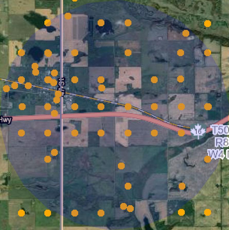
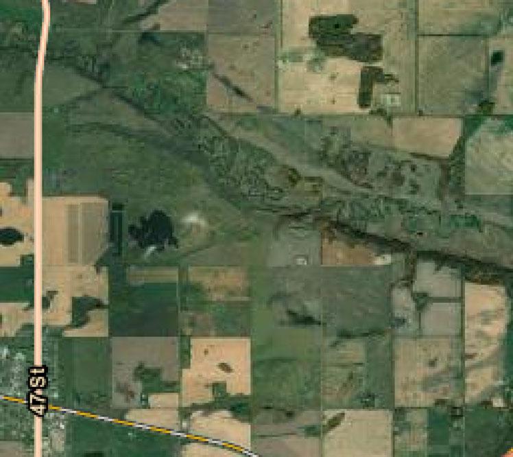
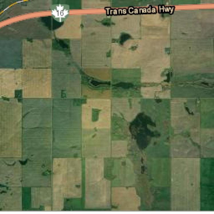
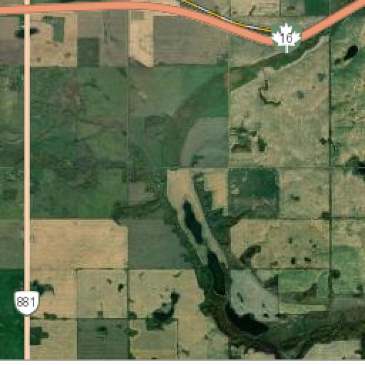


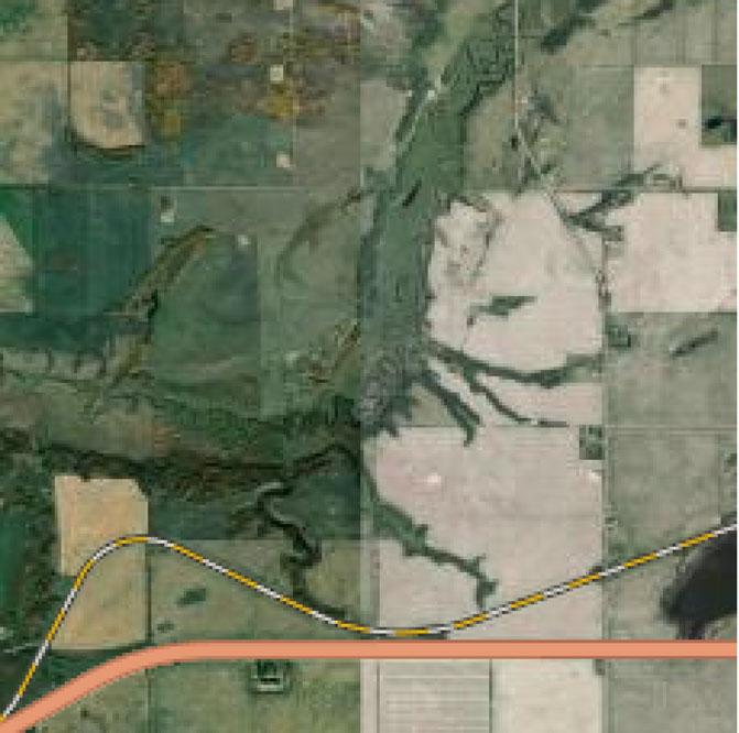
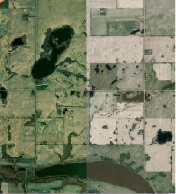
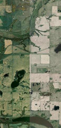


Groundwater Wells
GIC Well ID LSD SEC TWP RGE M DRILLING COMPANY DATE COMPLETED DEPTH (m) TYPE OF WORK USE CHM LT PT WELL OWNER STATIC LEVEL (m) TEST RATE (L/min) SC_DIA (cm) 151955 SW 30 50 8 4 MORTON'S WATER WELL DRILLING LTD. 1989-11-09 73.15 New Well Domestic 16 28 KAZLECHKO, STAN 24.08 36.37 12.70 158319 NE 28 50 8 4 FRED'S WATER WELL DRILLING LTD. 1976-08-14 50.60 New Well Stock 15 HENDERSON, ALEX 36.58 18.18 11.43 158428 1 30 50 8 4 MARTIN WATER WELLS 1991-04-17 29.26 Deepened Domestic 3 KITT, JIM 21.03 90.92 49.78 161546 NW 20 50 8 4 UNKNOWN DRILLER 67.06 Chemistry Domestic BURY, MICHAEL 0.00 161547 NW 20 50 8 4 UNKNOWN DRILLER 54.86 Chemistry Domestic BURY, MICHAEL 0.00 169596 SE 24 50 9 4 UNKNOWN DRILLER 83.82 Chemistry Domestic WAGNER, DON 0.00 169820 1 26 50 9 4 MARTIN WATER WELLS 1992-10-07 25.60 New Well Domestic & Stock 13 WUSYK, PAUL 1.52 9.09 0.00 232273 16 24 50 9 4 MCALLISTER WATERWELLS LTD. 1993-08-27 73.15 New Well Domestic 14 POLIAKIWSKI, ED/LINDA 28.04 36.37 12.70 241080 12 17 50 8 4 UNKNOWN DRILLER 7.32 Federal Well Survey Domestic & Stock CRAWFORD 0.00 241081 NW 21 50 8 4 FRED'S WATER WELL DRILLING LTD. 1977-05-04 71.02 New Well Domestic 19 PHILLIPS, BARRY 35.97 29.55 11.43 241083 SE 29 50 8 4 UNKNOWN DRILLER 68.88 Chemistry Domestic ANDERSON, ALBERT 54.86 0.00 241084 SE 29 50 8 4 MORTON'S WATER WELL DRILLING LTD. 1980-11-03 76.20 New Well Domestic & Stock 14 ANDERSON, ALBERT 26.21 45.46 11.43 242034 NW 25 50 9 4 PROSSER & BECKETT 1959-09-21 71.63 New Well Domestic 1 20 PARKS, J.H. 24.38 18.18 11.43 242100 5 31 50 8 4 MCALLISTER DRILLING LTD. 1969-10-09 60.35 New Well Stock 13 SARGENT BROS. 37.80 10.31 250716 NW 7 50 8 4 FRED'S WATER WELL DRILLING LTD. 1978-08-26 77.42 New Well Domestic 14 PULYK, JIM 17.37 11.68 250719 NE 7 50 8 4 UNKNOWN DRILLER 76.20 Chemistry Domestic PULYK, JIM 75.59 0.00 250741 NE 16 50 8 4 UNKNOWN DRILLER 24.38 Chemistry Domestic BAIN, WILLIAM 0.00 250743 SE 19 50 8 4 UNKNOWN DRILLER 76.20 Chemistry Domestic MCLEOD, JOHN 0.00 250744 SW 19 50 8 4 UNKNOWN DRILLER 12.19 Federal Well Survey Domestic & Stock 2 MCLEOD 60.96 250745 NW 19 50 8 4 UNKNOWN DRILLER 60.96 Chemistry Domestic MCLEOD, J. 42.67 0.00
Please click the water Well ID to generate the Water Well Drilling Report. Page: 1 / 5 Printed on 6/21/2022 12:54:45 PM
View in Imperial Export to Excel
Reconnaissance Report
Reconnaissance Report
GIC Well ID LSD SEC TWP RGE M DRILLING COMPANY DATE COMPLETED DEPTH (m) TYPE OF WORK USE CHM LT PT WELL OWNER STATIC LEVEL (m) TEST RATE (L/min) SC_DIA (cm) 250747 NW 19 50 8 4 MCALLISTER DRILLING LTD. 1965-07-09 73.76 New Well Domestic 14 MCLEOD, J. 29.87 36.37 0.00 250750 NE 19 50 8 4 FRED'S WATER WELL DRILLING LTD. 1987-03-02 57.61 New Well Domestic & Stock 12 GOLISH, JAMES 19.81 45.46 12.70 250753 SE 20 50 8 4 UNKNOWN DRILLER 30.48 Federal Well Survey Unknown WHARUFE 0.00 250755 SW 20 50 8 4 UNKNOWN DRILLER 18.29 Federal Well Survey Unknown WOODS 0.00 250756 NE 20 50 8 4 MCALLISTER DRILLING LTD. 1978-04-26 73.15 New Well Domestic & Stock 13 LANGLEY, MICHAEL 25.60 31.82 11.68 250759 NE 20 50 8 4 FRED'S WATER WELL DRILLING LTD. 1988-09-09 35.97 New Well Stock 9 BURY, JOHN 19.51 50.01 12.70 250761 SW 21 50 8 4 UNKNOWN DRILLER 6.40 Federal Well Survey Unknown CRAWFORD 0.00 250762 NW 21 50 8 4 FRED'S WATER WELL DRILLING LTD. 1977-05-09 73.15 New Well Domestic 17 DAIVES, A.J. 35.97 18.18 11.68 250766 NE 21 50 8 4 UNKNOWN DRILLER 1935-08-19 27.43 Federal Well Survey Unknown ROMAIUK 0.00 250768 NE 21 50 8 4 UNKNOWN DRILLER 53.34 Chemistry Domestic WANLIN, BOB 0.00 250769 NE 21 50 8 4 UNKNOWN DRILLER 67.06 Chemistry Domestic MACLEOD, MALCOLM 0.00 250771 NE 21 50 8 4 UNKNOWN DRILLER 68.58 Chemistry Domestic WANLIN, BOB 0.00 250983 SW 28 50 8 4 MCALLISTER DRILLING LTD. 1977-09-20 73.15 New Well Domestic & Stock 7 POLIAKIWSKI, BRIAN 32.31 31.82 11.68 250985 NW 28 50 8 4 UNKNOWN DRILLER 1935-01-01 33.53 Federal Well Survey Domestic & Stock 4 SLOAN, T. 21.34 0.00 250986 NE 28 50 8 4 UNKNOWN DRILLER 1948-01-01 48.77 Chemistry Domestic HENDERSON, ALLAN 37.19 0.00 250987 NE 28 50 8 4 UNKNOWN DRILLER 54.86 Chemistry Unknown 0.00 250989 SE 29 50 8 4 PROSSER & BECKETT 1959-01-01 57.91 New Well Domestic & Stock 11 ANDERSON, ALBERT 24.38 22.73 11.68 250991 NW 29 50 8 4 DOWNEY GORDON B 32.00 New Well Domestic & Stock 3 ANDERSON, ARTHUR 21.34 22.73 11.68 250992 NW 29 50 8 4 UNKNOWN DRILLER 29.87 Federal Well Survey Unknown 3 MACMILLAN 21.95 60.96 250993 SE 30 50 8 4 UNKNOWN DRILLER 27.43 Federal Well Survey Domestic & Stock EMSLAND 25.91 0.00 Page: 2 / 5 Printed on 6/21/2022 12:54:45 PM
View in Imperial Export to Excel
Reconnaissance Report
GIC Well ID LSD SEC TWP RGE M DRILLING COMPANY DATE COMPLETED DEPTH (m) TYPE OF WORK USE CHM LT PT WELL OWNER STATIC LEVEL (m) TEST RATE (L/min) SC_DIA (cm) 250994 4 30 50 8 4 BYRT, STAN & SONS LTD. 1983-05-10 66.14 New Well Municipal 1 17 MANNVILLE, VILL OF 26.21 136.38 17.78 250995 SW 30 50 8 4 UNKNOWN DRILLER 0.00 Chemistry Domestic MANNVILLE#HOSPITAL 0.00 250996 NW 30 50 8 4 FRED'S WATER WELL DRILLING LTD. 1988-12-06 67.36 New Well Domestic & Stock 15 MARON, MARVIN 25.30 22.73 12.70 250997 SE 31 50 8 4 UNKNOWN DRILLER 85.34 Chemistry Unknown SARGENT, W. 0.00 251000 SW 32 50 8 4 UNKNOWN DRILLER 0.00 Chemistry Unknown ANDERSON, ARTHUR 0.00 251053 NE 13 50 9 4 FRED'S WATER WELL DRILLING LTD. 1979-09-26 50.90 New Well Domestic & Stock 10 BURY, JOHN 39.62 25.00 11.68 251054 16 13 50 9 4 PROSSER & BECKETT 1960-09-23 68.58 New Well Domestic 11 BURY, STAN/JOHN 39.62 22.73 11.43 251156 SE 24 50 9 4 UNKNOWN DRILLER 76.20 Chemistry Domestic WAGNER, RICHARD 0.00 251158 SW 24 50 9 4 UNKNOWN DRILLER 0.00 Chemistry Domestic & Stock STORCH, MARGARET 0.00 251159 SE 25 50 9 4 BYRT, STAN & SONS LTD. 1974-01-03 66.75 New Well Municipal 9 66 MANNVILLE, VILL OF #3 25.60 113.65 13.97 251171 NE 24 50 9 4 UNKNOWN DRILLER 0.00 Chemistry Stock POLIAKIWSKI, ED 0.00 251174 9 24 50 9 4 MCALLISTER DRILLING LTD. 1964-08-17 68.88 New Well Unknown 11 POLIAKIWSKI, E. 24.69 40.91 0.00 251176 SE 25 50 9 4 DOWNEY GORDON B 1950-06-30 11.58 New Well Unknown 4 VUMA, W. 4.57 9.09 0.00 251178 SE 25 50 9 4 UNKNOWN DRILLER 75.59 Chemistry Domestic MANNVILLE#HOSPITAL 39.01 0.00 251179 7 25 50 9 4 WESTERN WATER WELLS LTD. 1956-10-09 70.10 New Well Municipal 5 6 MANNVILLE, VILL OF #2 42.67 21.92 251179 7 25 50 9 4 WESTERN WATER WELLS LTD. 1956-10-09 70.10 New Well Municipal 5 6 MANNVILLE, VILL OF #2 23.16 113.65 21.92 251181 SE 25 50 9 4 UNKNOWN DRILLER 32.31 Federal Well Survey Unknown 3 BROWN 14.02 0.00 251182 SE 25 50 9 4 UNKNOWN DRILLER 0.00 Chemistry Domestic STADEN, KENT 0.00 251184 SW 25 50 9 4 UNKNOWN DRILLER 1953-06-17 51.82 Chemistry Domestic MANNVILLE#SHOOL 9.14 0.00 251185 SE 25 50 9 4 RANGELAND DRILLING 1965-05-11 68.58 New Well Domestic 15 RODER, FRITZ 25.60 31.82 11.68 Page: 3 / 5 Printed on 6/21/2022 12:54:45 PM
View in Imperial Export to Excel
Reconnaissance Report
GIC Well ID LSD SEC TWP RGE M DRILLING COMPANY DATE COMPLETED DEPTH (m) TYPE OF WORK USE CHM LT PT WELL OWNER STATIC LEVEL (m) TEST RATE (L/min) SC_DIA (cm) 251185 SE 25 50 9 4 RANGELAND DRILLING 1965-05-11 68.58 New Well Domestic 15 RODER, FRITZ 25.60 13.64 11.68 251198 3 25 50 9 4 MCALLISTER HOLDINGS LTD. 1979-05-25 60.96 New Well Domestic 10 KAZIECHKO, STAN 27.74 36.37 11.43 251201 4 25 50 9 4 UNKNOWN DRILLER 21.95 Test Hole Unknown 6 ALTA ENV/WATER RES 0.00 251204 NE 25 50 9 4 UNKNOWN DRILLER 0.00 Chemistry Domestic DELISLE, JOSEPH 0.00 251207 NE 25 50 9 4 FRED'S WATER WELL DRILLING LTD. 1988-03-06 63.09 New Well Domestic & Stock 13 PRIESTON, AUSTIN/RITA 26.21 25.00 12.70 251212 25 50 9 4 UNKNOWN DRILLER 60.96 Chemistry Unknown PEMBERTON 21.34 0.00 258223 NW 29 50 8 4 BIG IRON DRILLING LTD. 1995-06-20 42.06 New Well Domestic 11 15 ANDERSON, AURTHER 26.52 45.46 15.24 281255 7 25 50 9 4 UNKNOWN DRILLER 1980-03-19 0.00 Chemistry Domestic 1 ROBIN, ROLAND 0.00 281265 NW 25 50 9 4 UNKNOWN DRILLER 1973-05-10 60.96 Chemistry Domestic 1 WEAVER, ROBERT 0.00 287661 SW 17 50 8 4 MORTON'S WATER WELL DRILLING LTD. 1997-09-03 79.25 New Well Domestic 8 13 ROLAND, ROBIN 37.98 36.37 12.70 287999 8 25 50 9 4 UNKNOWN DRILLER 26.82 Test Hole Observation MANNVILLE 8.89 289352 SW 25 50 9 4 MARTIN WATER WELLS 1998-05-20 15.85 Reconditioned Stock 2 WUSYK, PAUL 1.83 136.38 59.99 290832 SW 19 50 8 4 MANNVILLE WATER WELL SERVICES LTD. 1998-09-26 44.20 New Well Domestic 10 7 MORTON, ALAN 25.60 54.55 12.70 292026 NW 19 50 8 4 MANNVILLE WATER WELL SERVICES LTD. 1998-10-29 64.01 New Well Observation 16 MANNVILLE, VILL OF 0.00 293960 NE 20 50 8 4 MORTON'S WATER WELL DRILLING LTD. 2000-04-07 73.15 New Well Domestic 9 25 HENDERSON, ALEX D. 25.82 36.37 12.70 1025507 3 33 50 8 4 ACCESS WATERWELLS INC. 2013-03-17 149.96 New Well Industrial 24 10 PERPETUAL ENERGY 42.67 26.50 17.78 1025508 3 33 50 8 4 ACCESS WATERWELLS INC. 2013-03-19 59.44 New Well Observation 16 17 PERPETUAL ENERGY 44.20 11.37 14.12 1485043 NE 25 50 9 4 MANNVILLE WATER WELL SERVICES LTD. 2002-08-14 67.97 New Well Domestic & Stock 18 25 KONIECZNY, KELLY 26.24 50.01 12.70 1485047 NW 24 50 9 4 MANNVILLE WATER WELL SERVICES LTD. 2002-05-04 68.58 New Well Domestic 12 25 GAUSVIK, DOUG 29.17 54.55 12.70 1485099 SW 16 50 8 4 MANNVILLE WATER WELL SERVICES LTD. 2006-06-08 79.55 New Well Domestic & Stock 12 25 WEATHERAL, STANLEY 31.42 45.46 12.70 Page: 4 / 5 Printed on 6/21/2022 12:54:45 PM
View in Imperial Export to Excel
Reconnaissance Report
GIC Well ID LSD SEC TWP RGE M DRILLING COMPANY DATE COMPLETED DEPTH (m) TYPE OF WORK USE CHM LT PT WELL OWNER STATIC LEVEL (m) TEST RATE (L/min) SC_DIA (cm) 1485136 SE 25 50 9 4 MANNVILLE WATER WELL SERVICES LTD. 2007-07-11 67.06 New Well Domestic 17 25 KAZIECHKO, STANLEY 29.14 27.28 12.70 1490347 13 8 50 8 4 MARTIN WATER WELLS 2008-08-21 17.07 New Well Domestic 4 24 ELLIOT, DOUG 4.40 272.77 73.66 1490784 14 8 50 8 4 MARTIN WATER WELLS 2018-06-07 12.19 New Well Stock 7 26 ELLIOTT, DOUG 6.88 18.18 1924509 NE 21 50 8 4 MORTON'S WATER WELL DRILLING LTD. 2007-11-29 79.25 New Well Domestic 6 16 FAHSELT, RON 38.62 27.28 12.70 2092710 16 24 50 9 4 UNKNOWNDRILLINGCOMP11 66.75 Well Inventory Municipal 4 MANNVILLE, TOWN OF 25.60 9556000 1 25 50 9 4 WESTERN WATER WELLS LTD. 1953-12-01 76.20 New Well Municipal 12 1 MANNVILLE, TOWN OF 21.95 181.84 21.92 9556000 1 25 50 9 4 WESTERN WATER WELLS LTD. 1953-12-01 76.20 New Well Municipal 12 1 MANNVILLE, TOWN OF 21.95 113.65 21.92 9556000 1 25 50 9 4 WESTERN WATER WELLS LTD. 1954-10-15 76.20 Reconditioned Municipal 1 9 MANNVILLE, TOWN OF 24.08 113.65 21.92 Page: 5 / 5 Printed on 6/21/2022 12:54:45 PM
View in Imperial Export to Excel
APPENDIX F: SITE PHOTOGRAPHS
A THUNDERCHILD ENERGY SERVICES COMPANY Biophysical Desktop Assessment Project #: 22148 Client: County of Minburn No. 27 Creation Date: August 5, 2022 F

Proponent: County of Minburn No. 27
PHOTOGRAPHIC LOG
Date: July 20, 2022
Project Name: Biophysical Assessment X‐Terra Project: 22148 Location: NW‐19, NE‐19 & NW‐20‐
Photo: 1
Direction: W
Date: June 22, 2022
Description: Overview of future development area facing west.
Photo: 2
Direction: W
Date: June 22, 2022
Description: Viewing west at Ditch Wetland.
A THUNDERCHILD ENERGY SERVICES COMPANY
W3M Page 1 of 11 200, 4201 66th Ave. 100 ‐ 303 Wheeler Place Lloydminster, AB Saskatoon, SK T9V 2Y7 S7P 0A4 TEL (780) 875‐1442 TEL (306) 373 1110 FAX (780) 871‐0925 FAX 306 373 2444
050‐08 W4M4‐21‐044‐24
Proponent: County of Minburn No. 27
PHOTOGRAPHIC LOG
Date: July 20, 2022
Project Name: Biophysical Assessment X‐Terra Project: 22148
Location: NW‐19, NE‐19 & NW‐20‐050‐08 W4M4‐21‐044‐24
Photo: 3
Direction: E
Date: June 22, 2022
Description: Viewing east at Ditch Wetland.
Photo: 4
Direction: W
Date: June 22, 2022
Description: Viewing west at Ditch Wetland 2.
A THUNDERCHILD ENERGY SERVICES COMPANY
Page 2 of 11 200, 4201 66th Ave. 100 ‐ 303 Wheeler Place Lloydminster, AB Saskatoon, SK T9V 2Y7 S7P 0A4 TEL (780) 875‐1442 TEL (306) 373 1110 FAX (780) 871‐0925 FAX 306 373 2444
W3M
Proponent: County of Minburn No. 27
PHOTOGRAPHIC LOG
Date: July 20, 2022
Project Name: Biophysical Assessment X‐Terra Project: 22148
Location: NW‐19, NE‐19 & NW‐20‐050‐08 W4M4‐21‐044‐24 W3M
Photo: 5
Direction: E
Date: June 22, 2022
Description: Viewing east at Ditch Wetland 2.
Photo: 6
Direction: W
Date: June 22, 2022
Description: Viewing west at 1619 Wetland.
A THUNDERCHILD ENERGY SERVICES COMPANY
Page 3 of 11 200, 4201 66th Ave. 100 ‐ 303 Wheeler Place Lloydminster, AB Saskatoon, SK T9V 2Y7 S7P 0A4 TEL (780) 875‐1442 TEL (306) 373 1110 FAX (780) 871‐0925 FAX 306 373 2444
Proponent: County of Minburn No. 27
PHOTOGRAPHIC LOG
Date: July 20, 2022
Project Name: Biophysical Assessment X‐Terra Project: 22148 Location: NW‐19, NE‐19 & NW‐20‐050‐08 W4M4‐21‐044‐
Photo: 7
Direction: N
Date: June 22, 2022
Description: Viewing north at 16-19 Wetland.
Photo: 8
Direction: E
Date: June 22, 2022
Description: Viewing east at the CN Ditch.
A THUNDERCHILD ENERGY SERVICES COMPANY
Page 4 of 11 200, 4201 66th Ave. 100 ‐ 303 Wheeler Place Lloydminster, AB Saskatoon, SK T9V 2Y7 S7P 0A4 TEL (780) 875‐1442 TEL (306) 373 1110 FAX (780) 871‐0925 FAX 306 373 2444
24 W3M
Proponent: County of Minburn No. 27
PHOTOGRAPHIC LOG
Date: July 20, 2022
Project Name: Biophysical Assessment X‐Terra Project: 22148
Location: NW‐19, NE‐19 & NW‐20‐050‐08 W4M4‐21‐044‐24 W3M
Photo: 9
Direction: W
Date: June 22, 2022
Description: Viewing west at CN Ditch.
Photo: 10
Direction: W
Date: June 22, 2022
Description: Viewing west at CN Ditch Wetland.
A THUNDERCHILD ENERGY SERVICES COMPANY
Page 5 of 11 200, 4201 66th Ave. 100 ‐ 303 Wheeler Place Lloydminster, AB Saskatoon, SK T9V 2Y7 S7P 0A4 TEL (780) 875‐1442 TEL (306) 373 1110 FAX (780) 871‐0925 FAX 306 373 2444
Proponent: County of Minburn No. 27
PHOTOGRAPHIC LOG
Date: July 20, 2022
Project Name: Biophysical Assessment X
Terra Project: 22148
Photo: 11
Direction: N
Date: June 22, 2022
Description: Viewing North at CN Ditch Wetland.
Photo: 12
Direction: N
Date: June 22, 2022
Description: Viewing north at CN Ditch Wetland.
A THUNDERCHILD ENERGY SERVICES COMPANY
24 W3M Page 6 of 11 200, 4201 66th Ave. 100 ‐ 303 Wheeler Place Lloydminster, AB Saskatoon, SK T9V 2Y7 S7P 0A4 TEL (780) 875‐1442 TEL (306) 373 1110 FAX (780) 871‐0925 FAX 306 373 2444
‐
Location: NW‐19, NE‐19 & NW‐20‐050‐08 W4M4‐21‐044‐
Proponent: County of Minburn No. 27
PHOTOGRAPHIC LOG
Date: July 20, 2022
Project Name: Biophysical Assessment X‐Terra Project: 22148 Location: NW‐19, NE‐19 & NW‐20‐050‐08 W4M4‐
Photo: 13
Direction: E
Date: June 22, 2022
Description: Viewing east at CN Ditch Wetland.
Photo: 14
Direction: W
Date: June 22, 2022
Description: Viewing west at ASP Lands area.
A THUNDERCHILD ENERGY SERVICES COMPANY
Page 7 of 11 200, 4201 66th Ave. 100 ‐ 303 Wheeler Place Lloydminster, AB Saskatoon, SK T9V 2Y7 S7P 0A4 TEL (780) 875‐1442 TEL (306) 373 1110 FAX (780) 871‐0925 FAX 306 373 2444
21‐044‐24 W3M
Proponent: County of Minburn No. 27
PHOTOGRAPHIC LOG
Date: July 20, 2022
Project Name: Biophysical Assessment X‐Terra Project: 22148
Photo: 15
Direction: E
Date: June 22, 2022
Description: Viewing east at ASP Lands area.
Photo: 16
Direction: SW
Date: June 22, 2022
Description: Viewing southwest at ASP Lands area.
A THUNDERCHILD ENERGY SERVICES COMPANY
Page 8 of 11 200, 4201 66th Ave. 100 ‐ 303 Wheeler Place Lloydminster, AB Saskatoon, SK T9V 2Y7 S7P 0A4 TEL (780) 875‐1442 TEL (306) 373 1110 FAX (780) 871‐0925 FAX 306 373 2444
Location: NW‐19, NE‐19 & NW‐20‐050‐08 W4M4‐21‐044‐24 W3M
Proponent: County of Minburn No. 27
PHOTOGRAPHIC LOG
Date: July 20, 2022
Project Name: Biophysical Assessment X‐Terra Project: 22148
Photo: 17
Direction: N
Date: June 22, 2022
Description: Viewing north at the watercourse in the northwest corner of the ASP Lands area.
Photo: 18
Direction: E
Date: June 22, 2022
Description: Viewing east at watercourse in the northwest corner of the ASP Lands area.
A THUNDERCHILD ENERGY SERVICES COMPANY
08
21
044
24 W3M Page 9 of 11 200, 4201 66th Ave. 100 ‐ 303 Wheeler Place Lloydminster, AB Saskatoon, SK T9V 2Y7 S7P 0A4 TEL (780) 875‐1442 TEL (306) 373 1110 FAX (780) 871‐0925 FAX 306 373 2444
Location: NW‐19, NE‐19 & NW‐20‐050‐
W4M4‐
‐
‐
Proponent: County of Minburn No. 27
PHOTOGRAPHIC LOG
Date: July 20, 2022
Project Name: Biophysical Assessment X‐Terra Project: 22148
Location: NW‐19, NE‐19 & NW‐20‐050‐08 W4M4‐21‐044‐24
Photo: 19
Direction: NW
Date: June 22, 2022
Description: Viewing northwest at ASP Lands area.
Photo: 20
Direction: W
Date: June 22, 2022
Description: Viewing west at ASP Lands area.
A THUNDERCHILD ENERGY SERVICES COMPANY
Page 10 of 11 200, 4201 66th Ave. 100 ‐ 303 Wheeler Place Lloydminster, AB Saskatoon, SK T9V 2Y7 S7P 0A4 TEL (780) 875‐1442 TEL (306) 373 1110 FAX (780) 871‐0925 FAX 306 373 2444
W3M
Proponent: County of Minburn No. 27
PHOTOGRAPHIC LOG
Date: July 20, 2022
Project Name: Biophysical Assessment X‐Terra Project: 22148 Location: NW‐19, NE‐19 & NW‐20‐
Photo: 21
Direction: SE
Date: June 22, 2022
Description: Viewing southeast at the borrow pit/wetland near the southwest corner of the ASP Lands area.
Photo: 22
Direction: W
Date: June 22, 2022
Description: Viewing west at the borrow pit/wetland near the southwest corner of the ASP Lands area.
A THUNDERCHILD ENERGY SERVICES COMPANY
24 W3M Page 11 of 11 200, 4201 66th Ave. 100 ‐ 303 Wheeler Place Lloydminster, AB Saskatoon, SK T9V 2Y7 S7P 0A4 TEL (780) 875‐1442 TEL (306) 373 1110 FAX (780) 871‐0925 FAX 306 373 2444
050‐08 W4M4‐21‐044‐
APPENDIX G: ANNUAL CROP INVENTORY
A THUNDERCHILD ENERGY SERVICES COMPANY Biophysical Desktop Assessment Project #: 22148 Client: County of Minburn No. 27 Creation Date: August 5, 2022 G


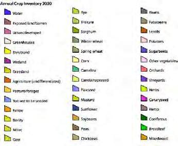
19 20 29 30
TITLE: PROJECT: S:\GIS\2022_Projects\County of Minburn\22148_County of Minburn(Red Willow) ASP 2022\MXDs\1Report\22148 COUNTY OF MINBURN RED WILLOW.mxd 0 500 M RED WILLOW PROJECT 2020 ANNUAL CROP INVENTORY 3 REFERENCE: NATURAL RESOURCES CANADA, CENTRE FOR TOPOGRAPHIC INFORMATION, 2012; ALBERTA ENVIRONMENT AND SUSTAINABLE RESOURCE DEVELOPMENT AIR PHOTO DISTRIBUTION; GOOGLE EARTH, ESRI, BING IMAGERY AGRICULTURE AND AGRI-FOOD CANADA, NAD_1983_10TM_AEP_FOREST QUARTERSECTION PROJECT FOOTPRINT HIGHWAY LEGEND DATE DRAWN 2022-08-04 DATUM PROJECTION NAD 83 UTM Z12 SCALE 1:12,500 JC REVIEWED VERSION R1 CB 10TM AEP F
FIGURE:
B Appendix B Geotechnical Report
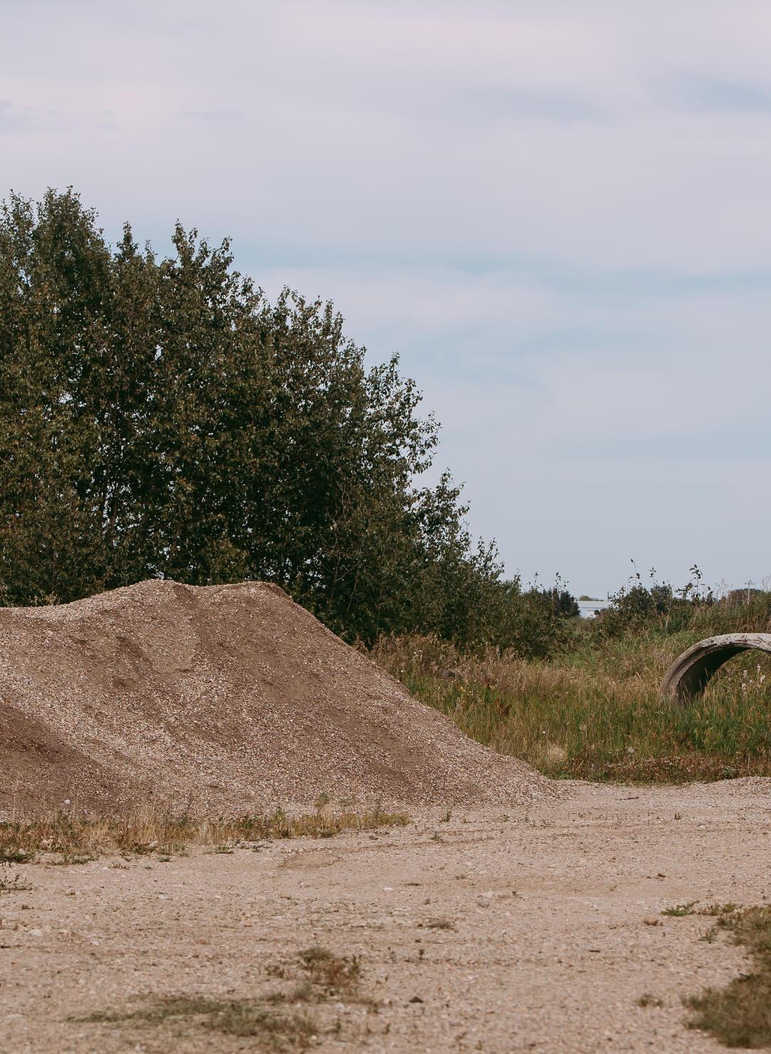
Does not form part of this Bylaw.
Prepared by: SolidEarth Geotechnical Inc.

Edmonton : Tel.: 780.577.1115
Fax: 780.669.7094
4336 97 Street Edmonton, AB, T6E 5R9
GEOTECHNICAL INVESTIGATION
Proposed East Industrial Park ASP Within Portions of N ½ 19-50-8 W4M Village of Mannville Alberta
Prepared for:
BAR Engineering Co. Ltd.
Date: 4 April 2023
Project File #: PG23-1691
Cold Lake : Tel.: 780.545.3545
Fax: 780.669.7094
#105, 4604 50 Street Cold Lake, AB, T9M 1S6 Lloydminster : Tel.:
5406 52 Avenue Lloydminster, AB, T9V 2T5
SolidEarth Geotechnical Inc. www.solidearth.ca
780.875.2112 Fax: 780.669.7094
PG23-1691 - Proposed Mannville Industrial Park ASP - Final Report Page i Geotechnical Investigation Proposed East Industrial Subdivision ASP Within Portions of N ½ 19-50-8 W4M Village of Mannville Alberta Table of Contents Page 1.0 INTRODUCTION 1 2.0 PROJECT DESCRIPTION AND INVESTIGATION SCOPE ............................................ 1 3.0 SITE DESCRIPTION 1 4.0 FIELD AND LABORATORY INVESTIGATION ................................................................1 4.1 GROUND DISTURBANCE AND SAFETY PERFORMANCE 1 4.2 FIELD DRILLING AND TESTING 2 4.3 LABORATORY INVESTIGATION 2 5.0 SUBSURFACE CONDITIONS 3 6.0 REVIEW OF AVAILABLE INFORMATION ......................................................................4 7.0 PRELIMINARY GEOTECHNICAL ANALYSIS AND RECOMMENDATIONS 6 7.1 FOREWORD .......................................................................................................6 7.2 SITE DEVELOPMENT CONSIDERATIONS 6 7.2.1 Subgrade Preparation 6 7.2.2 Requirement for Engineered Fill ...............................................................7 7.2.3 Site Drainage 8 7.3 FOUNDATION OPTIONS AND PRELIMINARY DESIGN CONSIDERATIONS .... 8 7.3.1 Foundation Options 9 7.3.2 Foundations Design Method .....................................................................9 7.3.3 CIP Concrete Piles 11 7.3.4 Frost Considerations for Piles and Grade Beams ................................... 13 7.4 RECOMMENDATION FOR STORM WATER MANAGEMENT FACILITY 13 7.4.1 Anticipated Subsurface Conditions 14 7.4.2 Subgrade Preparation and Inspection .................................................... 14 7.4.3 Long-term slope stability consideration 15 7.4.4 Groundwater Management during Construction ..................................... 15 7.4.5 Compacted Clay Liner Consideration 15 7.5 INSTALLATION OF BURIED UTILITIES ............................................................ 17 7.5.1 Trench Excavation 17 7.5.2 Trench Backfill 18 7.5.3 Groundwater Consideration and Control................................................. 18 7.5.4 Installation of Underground Utilities 19 7.5.5 Manhole Structures ................................................................................19 7.6 PAVEMENT STRUCTURE 19 7.6.1 Frost Susceptibility of Soils ..................................................................... 19 7.6.2 Surface Water Management Considerations 20 7.6.3 Asphalt Pavement Design Section.......................................................... 21 8.0 TESTING AND INSPECTION 22 9.0 CLOSURE 23
Figures:
Geotechnical Investigation
Proposed East Industrial Subdivision ASP Within Portions of N ½ 19-50-8 W4M Village of Mannville Alberta
Figure 1: Project Layout and Borehole Location Plan
Figure 2: 2016 Aerial Photograph of the Site
Figure 3: 2007 Aerial Photograph of the Site
Figure 4: Atlas of Canada – Toporama Maps
Figure 5: Approximate Site Location and Oil and Gas Infrastructure
Tables:
Table 1: Measured Groundwater Levels
Table 2: Geotechnical Resistance Factors for Foundations
Table 3: Recommended Unfactored (Ultimate) Shaft Friction Resistance
Table 4: Flexible Asphaltic Concrete Pavement Design
Appendix A: Site Photographs Taken During the Field Investigation
Appendix B: Borehole Logs
Explanation of Terms and Symbols
Appendix C: Water Well Drilling Reports
PG23-1691 - Proposed Mannville Industrial Park ASP - Final Report Page ii
1.0 INTRODUCTION
Geotechnical Investigation
Proposed East Industrial Subdivision ASP
Within Portions of N ½ 19-50-8 W4M Village of Mannville Alberta
This report presents the results of the geotechnical investigation conducted for the proposed East Industrial Park, located on the east side of the Village of Mannville, Alberta. The geotechnical investigation was carried out by SolidEarth Geotechnical Inc. (SolidEarth) at the authorization of Mr. Scott Simons, P.Eng. of BAR Engineering Co. Ltd. (BAR Engineering).
The purpose of the geotechnical investigation was to assess the subsurface soil and groundwater conditions at selected locations across the proposed subdivision and to provide geotechnical recommendations associated with the proposed development
2.0 PROJECT DESCRIPTION AND INVESTIGATION SCOPE
Based on information provided to SolidEarth, it was understood that BAR Engineering is preparing an area structure plan (ASP) for the project, which involves expanding the industrial subdivision
The scope of work completed by SolidEarth included a desktop review of published aerial imagery and geological information; drilling boreholes, conducting laboratory review and testing on recovered soil samples; and undertaking geotechnical engineering analysis and preparation of this report.
3.0 SITE DESCRIPTION
The site was located within portions of N ½ 19-50-8 W4M, on the east side of the Village. At the time of the field investigation, the site was generally agricultural cropland and was relatively flat The western side of the project area bordered on the existing industrial area. A dugout was present within the southwestern portion of the site.
A Canadian National (CN) railway and Township Road 503B traversed the site diagonally northwest to southeast. A residential acreage existed within the central portion of the site, on the south side of Township Road 503B.
The overall site development plan on an aerial photograph is presented as Figure 1. Photographs showing site conditions that existed at the time of the field investigation are presented in Appendix A.
4.0 FIELD AND LABORATORY INVESTIGATION
4.1 GROUND DISTURBANCE AND SAFETY PERFORMANCE
Prior to field drilling, a SolidEarth representative completed internal ground disturbance procedures, which included placing an Alberta One Call. Before starting onsite work, a daily
PG23-1691 - Proposed Mannville Industrial Park ASP - Final Report Page 1
Geotechnical Investigation
Proposed East Industrial Subdivision ASP
Within Portions of N ½ 19-50-8 W4M
Village of Mannville Alberta
field level hazard assessment was conducted and was communicated with all workers involved during the tailgate meeting. The field work was completed without any near misses or incidents.
4.2 FIELD DRILLING AND TESTING
The borehole locations were selected and marked in the field by BAR Engineering. The borehole location plan on an aerial photograph is presented as Figure 1.
SolidEarth subcontracted Evergreen Drilling Ltd. of Wetaskiwin, Alberta to drill the boreholes. Drilling was completed using a track and truck-mounted auger drill rig utilizing 150 mm solidstem continuous flight augers.
The field investigation was undertaken on 9 March 2023 and consisted of drilling six (6) boreholes (BH23-1 to -6). The boreholes were drilled to approximate depths ranging between 5.8 and 7.3 m below the existing ground surface
During drilling, soil samples were collected at approximately 0.75 m intervals along the depth of the boreholes. Pocket penetrometer testing was conducted on selected cohesive soil samples to obtain an indication of the unconfined compressive strength of disturbed soil samples from the auger. Standard Penetration Tests (SPT) were conducted at selected depths (typically every 1.5 m) to assess the in-situ strength of the soils encountered. The soil sampling and testing sequences are shown on the borehole logs, Appendix B.
A SolidEarth geotechnical engineer monitored the drilling operations and logged the recovered soil samples from the auger cuttings and the SPT samples. The soils were logged according to the Modified Unified Soil Classification System, which is described in the Explanation of Terms and Symbols in Appendix B. Due to the method by which the soil cuttings were returned to surface, the depths noted on the borehole logs may vary by ± 0.3 m from those recorded.
Groundwater seepage conditions were monitored during and immediately following completion of drilling. Slotted standpipe piezometers were installed at all borehole locations at completion of drilling to monitor short term groundwater levels.
The lateral and vertical coordinates (northing, easting and elevation) of the ground surface at the borehole locations were surveyed by BAR Engineering and provided to SolidEarth. These coordinates are shown on the borehole logs
4.3 LABORATORY INVESTIGATION
All collected samples were submitted to the laboratory for further examination and testing. Laboratory testing conducted included visual examination, determination of the natural moisture content on all collected samples; grain size distribution and Atterberg limits on selected samples. The results of the laboratory testing are presented on the borehole logs, Appendix B.
PG23-1691 - Proposed Mannville Industrial Park ASP - Final Report Page 2
5.0 SUBSURFACE CONDITIONS
Geotechnical Investigation
Proposed East Industrial Subdivision ASP
Within Portions of N ½ 19-50-8 W4M
Village of Mannville Alberta
The subsurface soil conditions encountered at the borehole locations generally consisted of cultivated topsoil followed by sand and underlain by clay till. A brief summary of the subsurface conditions encountered is presented below. A detailed description of the subsurface conditions encountered at each borehole location is provided on the borehole logs.
Cultivated Topsoil
Cultivated topsoil was encountered at the ground surface of all borehole locations and was generally less than 75 mm thick.
Sand
Near surface sand was encountered below the topsoil at the majority of borehole locations and extended to approximate depths ranging between 0.5 and 0.8 m below ground surface.
The sand was classified as “sand, some to and gravel, trace to some silt, trace to some clay”, was poorly graded, fine to coarse grained, brown, and damp to very moist
Clay Till
Clay till was encountered below the near surface sand at all borehole locations and extended to beyond the borehole exploration depths
The clay till was generally classified as “clay, sandy to and sand, and silt”, was low to medium plastic, brown to grey, and moist. The natural moisture content of the clay till samples ranged between 8 and 19 percent, with an average of 14 percent. Liquid and plastic limits of samples were in the order of 31 to 35 percent, and 10 to 11 percent, respectively. Based on the comparison of the plastic limit of the soil, it is expected that the average moisture content of the clay till was generally near to the optimum moisture content of the soil
The consistency of the clay till was assessed based on SPT “N” and pocket penetrometer values to be generally firm to stiff within the upper 2 m of the soil profile, becoming stiff to very stiff below that depth.
Groundwater Levels
The measured groundwater levels are shown in Table 1. The groundwater levels are expected to fluctuate seasonally depending upon several factors that include the local geology, hydrogeology, and surface infiltration.
PG23-1691 - Proposed Mannville Industrial Park ASP - Final Report Page 3
Geotechnical Investigation
Proposed East Industrial Subdivision ASP Within Portions of N ½ 19-50-8 W4M Village of Mannville Alberta
Table 1: Measured Groundwater Levels
Note 1: mbgs – metres below existing ground surface
Note 2: Provided to SolidEarth by the Client
6.0 REVIEW OF AVAILABLE INFORMATION
Aerial Photographs
Aerial photographs of the project site were obtained to determine the historic land features, use, and the changes that occurred within the project area. Aerial photographs were obtained through Google Earth Pro®. Aerial photographs that were reviewed included the years of 2021, 2016, and 2007
As aerial photographs do not provide a continuous record of site development, it is possible that features of interest may have been present in the study area between the dates of coverage. In addition, photographic quality and scale are variable and may make features difficult to identify or their nature difficult to determine.
A reproduction of the 2021, 2016, and 2007 aerial photographs are presented in Figures 1 to 3, respectively A review of these photographs indicated that the study area appeared to be mainly agricultural cropland throughout the review period with no major changes in land use or site features. A residential unit was noted within the middle of the site. Potentially wet and treed areas were noted within the central portion of the site. A dugout/pond was visible within the southwestern portion of the site A drainage pathway crossing the site in the north-south direction and crossing the CN ROW and highway were also noted
The review of historical aerial photographs identified no major historical land disturbance within the site. The review also identified the presence of potentially wet and vegetated areas within the middle portion of the site
PG23-1691 - Proposed Mannville Industrial Park ASP - Final Report Page 4
Borehole ID Depth of Borehole (mbgs) Note 1 Approximate Ground Elevation (m) Note 2 Groundwater Levels (At Drilling Completion) 20 March 2020 Depth (mbgs) Elevation (m) Depth (mbgs) Elevation (m) BH23-1 5.8 623.7 Dry Dry Dry Dry BH23-2 6.6 624.2 6.6 617.6 4.0 613.6 BH23-3 7.3 626.1 Dry Dry Dry Dry BH23-4 7.3 625.0 Dry Dry Dry Dry BH23-5 7.3 625.3 Dry Dry Dry Dry BH23-6 7.3 626.6 Dry Dry 1.9 624.7
Site Topography and Drainage
Geotechnical Investigation
Proposed East Industrial Subdivision ASP Within Portions of N ½ 19-50-8 W4M Village of Mannville Alberta
Site topography and drainage was assessed by reviewing Atlas of Canada-Toporama from the Natural Resources Canada website, as shown on Figure 4.
According to the Atlas of Canada-Toporama, the elevation of the study area has a relief of less than 10 m In addition, there appeared to be a low-lying area within the southwest portion of the site.
Surficial and Bedrock Geological Maps
The surficial geology of Alberta (Alberta Geological Survey Map 601 – Surficial Geology of Alberta by M.M. Fenton, E.J. Waters, S.M. Pawley, N.Atkinson, D.J. Utting and K. Mckay) was reviewed to assess the surficial geology of the study area. The reviewed information revealed that the surficial geology of the study area was composed of glacial moraine till which consists of clay, silt, and sand, with trace pebbles, cobbles, and boulders It is characterized by a lack of distinctive topography. This deposit may also contain blocks of bedrock, stratified sediments, or lenses of glaciolacustrine and/or glaciofluvial sediments.
Based on the bedrock geology by Alberta Geological Survey and Alberta Energy Regular (Alberta Geological Survey Map 600 – Bedrock Geology of Alberta), the bedrock was composed of Lower Belly River Group (KBR-I). The bedrock was described as very fine to medium grained, buff weathering sandstone; thin coal layers; brownish-grey, carbonaceous silty mudstone; sandstone-dominated, coarsening-upward members interlocked with mudstone.
Water Wells Drilling Logs
The Alberta Water Well Drilling Reports database was reviewed to obtain information regarding wells that may be present on the site and around the study area. The search indicated the presence of two (2) water wells within the vicinity and in the study area.
The well logs indicated that the soil profile mainly consisted of clay and sand deposits and underlain by bedrock consisting of shale and sandstone. The top of the bedrock was noted to be approximately 28 to 41 m below ground surface. The static water level was measured at 19.8 m below ground surface. A copy of the search results is provided in Appendix C.
Oil and Gas Installations
The Abacus Datagraphics Limited (AbaData) database was reviewed for information available to the Alberta Energy Regulator (AER) on oil and gas wells, facilities, batteries, and environmental spills related to the Site.
PG23-1691 - Proposed Mannville Industrial Park ASP - Final Report Page 5
The search indicated the followings:
Geotechnical Investigation
Proposed East Industrial Subdivision ASP Within Portions of N ½ 19-50-8 W4M Village of Mannville Alberta
• An ATCO gas pipeline running diagonally and entering the southwest corner of the study area across Highway 16 and exiting towards the Village of Mannville.
• A Mitco gas pipeline entering the study area across Highway 16 towards the existing residential building located in the site
• A Mitco gas pipeline entering the northeast corner of the study area across Range Road 85 and exiting across Township Road 504.
• Three parallel Telus utility lines running diagonally along Canadian National Railway and one Telus utility line running horizontally along Township Road 504.
• Two water wells, one within the eastern portion of the study area and one within the western portion.
Figure 5 presents the approximate site location and oil and gas infrastructure, from the AbaData database.
7.0 PRELIMINARY GEOTECHNICAL ANALYSIS AND RECOMMENDATIONS
It should be noted that the provided recommendations and considerations, particularly as it relates to building foundations, should be treated as preliminary only. A detailed geotechnical investigation should be completed for each proposed industrial building/lot in the future during the detailed design stage.
7.1 FOREWORD
The subsurface soil conditions encountered at the borehole locations were considered suitable for the proposed development. Site grading, installation of underground utilities, construction of storm water management facility (SWMF), and pavement structures were considered feasible.
Based on the subsurface conditions encountered, deep pile foundations were considered most suitable foundations options for proposed future structures.
7.2 SITE DEVELOPMENT CONSIDERATIONS
7.2.1
Subgrade Preparation
During initial site grading, all topsoil should be stripped and removed from the site. Topsoil should not be mixed with mineral soils or be used as engineered fill material.
The near surface soil consisted of sand (up to 1 m thick) and clay till. As such, variability in subgrade conditions should be anticipated The near surface sand, where encountered, was
PG23-1691 - Proposed Mannville Industrial Park ASP - Final Report Page 6
Geotechnical Investigation
Proposed East Industrial Subdivision ASP
Within Portions of N ½ 19-50-8 W4M
Village of Mannville Alberta
generally poorly graded, and damp to moist. The near surface clayey soils were low to medium plastic. It is anticipated that:
• The exposed subgrade may be sensitive to disturbance from heavy rubber-tire construction equipment, especially if exposed to wet conditions.
• Soft subgrade conditions may be encountered at some locations across the site, particularly following snow melt and heavy rain events.
Construction traffic on the unprotected subgrade should be kept to a minimum and restricted to low pressure track equipment to the extent possible. The use of heavy rubber-tire equipment (such as rock trucks) during construction will likely lead to significant disturbance to the subgrade and should be avoided to the extent possible.
All exposed subgrade, following achievement of rough grades (in areas under cut) and prior to placement of engineered fill (in areas under fill) should be inspected by the geotechnical engineer. The inspection may include a proof-roll test to confirm that deflections from construction traffic are minimal. Soft and weak areas identified during inspection, should be strengthened and improved.
Regardless of the above, it is recommended that where subgrade support is required, the upper 300 mm of the subgrade soil be strengthened/improved. Subgrade strengthening/improvement would include scarifying and re-compacting the subgrade (if good weather conditions prevail) or the soft wet material removed and replaced with drier clay or granular material placed as engineered fill Requirements for engineered fill are discussed below.
7.2.2 Requirement for Engineered Fill
Engineered fill should consist of low to medium plastic clay or a well-graded granular material. Silt or sand which is uniformly graded, or which contains more than 10 percent passing the 0.080 mm sieve is not recommended as these materials are generally frost susceptible and are difficult to compact (require strict control of moisture content). All fill soils should be free from any organic materials, contamination, deleterious construction debris, and stones greater than 150 mm in diameter.
The low to medium plastic native clay till soil encountered at the borehole locations was generally considered suitable for re-use as engineered fill. Moisture conditioning of these soils may be required at some locations and will depend on weather conditions during construction.
The sand encountered below the topsoil at the borehole locations was considered “marginal” for engineered fill application. These soils are generally frost susceptible in the presence of water and may be become weak if inundated with water These may be re-used as general fill and where subgrade support is not required.
PG23-1691 - Proposed Mannville Industrial Park ASP - Final Report Page 7
Geotechnical Investigation
Proposed East Industrial Subdivision ASP
Within Portions of N ½ 19-50-8 W4M
Village of Mannville Alberta
Engineered fill should be thawed when placed and placed during non-frozen conditions. If winter construction is proposed, SolidEarth can provide additional recommendations once the overall development plan has been finalized.
All engineered fill should be compacted to a minimum of 98 percent of standard Proctor maximum dry density (SPMDD) within the proposed building envelopes, and to a minimum of 95 percent of SPMDD within the graveled yards and paved areas. Notwithstanding the above, the upper 300 mm of the subgrade within the paved areas should be compacted to 98 percent of SPMDD.
The fill should be compacted in lift thicknesses of 300 mm (loose) or less, and within two percent of the optimum moisture content of the soil. Engineered fill within the building footprint should extend at least 1.5 m, or the thickness of the fill, beyond the footprint of the building. Fill placement procedures and quality of the fill soils should be monitored by geotechnical personnel. Field monitoring should include compaction testing at regular frequencies.
Even for well compacted fill, some fill settlement under self-weight will occur. Settlement in the order of one to three percent of the fill thickness should be anticipated for engineered fill compacted to between 98 and 95 percent SPMDD. The majority of this settlement is expected to occur within the first year following construction.
7.2.3 Site Drainage
To minimize the potential for water ponding and saturation of the subgrade during and following construction, a minimum grade of two percent is recommended at the subgrade level to accommodate surface water runoff away from the development area. The upper 300 mm of backfill around the buildings (where no pavement structure is proposed) should consist of compacted clay to act as a seal against runoff water. The clay should extend a minimum distance of 3 m away from the building and should be graded at a slope of five percent or more.
It is also recommended that positive surface drainage be provided in the early stages of construction to prevent ponding of water and softening of the subgrade.
7.3 FOUNDATION OPTIONS AND PRELIMINARY DESIGN CONSIDERATIONS
As outlined above, the provided recommendations and considerations should be treated as preliminary only and should not be used in detailed design. A detailed geotechnical investigation should be completed for each proposed industrial building/lot in the future, during the detailed design stage.
PG23-1691 - Proposed Mannville Industrial Park ASP - Final Report Page 8
7.3.1 Foundation Options
Geotechnical Investigation
Proposed East Industrial Subdivision ASP
Within Portions of N ½ 19-50-8 W4M
Village of Mannville Alberta
The strength of the near surface soils (within the upper 1 to 3 m of soil profile) showed some degree of variability, and were relatively weak at a few borehole locations. As such, footings were not considered as a favourable foundation alternative at this time The suitability of shallow footings at specific locations should be addressed at the detailed design stage by site specific geotechnical investigations.
Based on the subsurface conditions encountered, deep pile foundations were considered to be the most suitable foundation option to supporting future proposed structures. Pile foundations may include cast-in-place (CIP) concrete piles, continuous flight auger piles (CFA), or driven steel piles. CIP concrete piles are anticipated to be the most economical deep pile foundation option. Preliminary recommendations for CIP concrete piles are provided in this report.
7.3.2 Foundations Design Method
The current design standard in foundation engineering is based on limit state design. Accordingly, geotechnical recommendations associated with such standard are provided in this report.
The 2006 Canadian Foundation Engineering Manual (2006 CFEM) defines limit states “as conditions under which a structure or its component members no longer perform their intended function”. Limit states are generally classified into two main groups: ultimate limit state and serviceability limit state. Below is a brief discussion on both states.
Ultimate Limit State (ULS)
Ultimate limit states are primarily concerned with collapse mechanisms for the structure and, hence, safety. For foundation design, the ULS consists of: ultimate bearing capacity failure, sliding, overturning, loss of stability, uplift, or large deformation.
The basic foundation design equation using ULS approach is presented as: 1 where:
ΦRn - is the factored geotechnical resistance
Φ - geotechnical resistance factor
Rn - the nominal (ultimate) geotechnical resistance determined using unfactored values for geotechnical parameters or performance data (such as pile load test)
1 Page 136 of the Canadian Foundation Engineering Manual – 4th Edition, January 2007
PG23-1691 - Proposed Mannville Industrial Park ASP - Final Report Page 9
SRniin α Σ≥Φ
Geotechnical Investigation
Proposed East Industrial Subdivision ASP
Within Portions of N ½ 19-50-8 W4M
Village of Mannville Alberta
ΣαiSni - is the summation of the factored overall load effects for a given load combination condition
αi - is the load factor corresponding to a particular load
Sni - is a specified load component of the overall load effects (e.g. dead load due to weight of structure or live load due to wind)
i - represents various types of loads such as dead load, live load, wind load, etc.
Geotechnical resistance factors as provided by the 2006 CFEM for foundations are provided in Table 2. The critical design events and their corresponding load combination and load factors should be assessed and determined by the structural engineer.
Table 2: Geotechnical Resistance Factors for Foundations
resistance to axial load
(i) semi-empirical analysis
(ii) analysis using static loading test results
Deep Foundations
(iii) analysis using dynamic monitoring results
(iv) uplift resistance by semi-empirical analysis
(v) uplift resistance using load test results
Serviceability Limit State (SLS)
Serviceability limit states are primarily concerned with mechanisms that restrict or constrain the intended use, occupancy, or function of the structure under working loads. For foundation design, SLS are usually associated with:
• excessive foundation movements (e.g. settlement, differential settlement, heave, etc.)
• unacceptable foundation vibrations
• local damage or deterioration
In general, the SLS criteria can be expressed as follows:
Serviceability Limit ≥ Effect of Service Loads
The soil bearing pressure under SLS conditions is evaluated using unfactored geotechnical parameters (settlement and compressibility properties), such that the bearing pressure does not cause the foundation to exceed the specified serviceability criteria.
PG23-1691 - Proposed Mannville Industrial Park ASP - Final Report Page 10
Type Loading Condition Geotechnical Resistance Factor (ULS)
Foundation
0.4 0.6 0.5 0.3 0.4 resistance to horizontal load 0.5
Geotechnical Investigation
Proposed East Industrial Subdivision ASP
Within Portions of N ½ 19-50-8 W4M
Village of Mannville Alberta
The soil-structure interaction and load-deformation characteristics of soils are non-linear and complex and depend on several considerations (e.g., foundations size and configuration, range of movement, etc.). The number of possible combinations is infinite and generic design charts cannot be prepared. Specific design charts under SLS conditions can be provided upon request and once preliminary design requirements have been established.
7.3.3 CIP Concrete Piles
Cast-in-place piles was considered suitable for the proposed development. The piles may require casing to maintain a dry and stable hole during construction if thick layers of saturated silt and sand layers are encountered.
Although cobbles/boulders were not encountered during drilling, this does not rule out the possibility of their existence within the clay till. Generally, if boulders are encountered at shallow depth, then excavation and removal of the boulders may be required. Deeper boulders may cause the abandonment of the pile and replacing it with a pile group with a cap that supports the columns. The piling contractor should be prepared to deal with cobbles/boulders, if encountered during pile installation.
Both straight shaft and belled piles may be considered for this site. Straight shaft piles should only be designed based on skin friction contribution. Belled piles may be designed based on skin friction and end bearing contribution.
The recommended unfactored (ultimate) shaft friction and end bearing parameters are provided in Table 3. These parameters were based on the soil profiles encountered during drilling and were determined mainly through semi-empirical correlations with the SPT and moisture content results. Accordingly, a geotechnical resistance factor of 0.4 should be used.
Note 1: mbgs - metres below the ground surface that existed at the time of the investigation
For SLS conditions, straight shaft piles designed with 70 to 80 percent of the factored ULS parameters are expected to undergo settlement equivalent to approximately 0.2 to 0.5 percent of the shaft diameter (for straight shaft piles) and 0.5 to 1 percent of the bell diameter for (belled piles) plus the elastic shortening of the pile
PG23-1691 - Proposed Mannville Industrial Park ASP - Final Report Page 11
Depth (mbgs) Note 1 Soil Type Un-factored (Ultimate) Shaft Friction (kPa) Un-factored (Ultimate) End Bearing (kPa) 0 to 2 Sand / Clay Till -2 to 6 Clay Till 45 6 to 7 Clay Till 45 750
Table 3: Preliminary Recommended Unfactored (Ultimate) Shaft Friction Resistance
Geotechnical Investigation
Proposed East Industrial Subdivision ASP
Within Portions of N ½ 19-50-8 W4M
Village of Mannville Alberta
In the design and installation of CIP piles, the following recommendations should be followed:
• A minimum pile spacing of 2.5 pile diameters, centre-to-centre, is recommended for friction piles. For belled piles, a minimum bell edge-to-edge spacing of 0.5 bell diameter should be maintained.
• The minimum recommended shaft diameter is 400 mm for straight shaft.
• The minimum recommended bell diameter is 750 mm.
• Seepage and sloughing conditions may be encountered during the installation of the CIP concrete piles, where thick layers of saturated sand or silt are intercepted by the pile hole. A steel casing should be used to allow for the construction of a dry and clean pile hole. The level of the fresh concrete in the casing should be maintained well above the level of the seepage zones as the casing is withdrawn to offset hydrostatic seepage pressures.
• End bearing contribution should only be considered if mechanical cleaning of the bell base is able to produce a bearing surface that is free of loose disturbed material and standing water. The geotechnical inspector should visually inspect (from the ground surface) the bell base and confirm suitable concrete placement conditions.
• For the design of pile foundations, it is important that the foundation designer accounts for the elevation difference between the final site grades and grades that existed at the time of the investigation. This will ensure that the pile bell is based on the proper soil strata during construction.
• The pile bell should be completely formed in the clay till. The base of the bell should be at least 0.3 m above any sand layer to prevent water seepage and to allow for the formation of a clean bell base. Similarly, the roof of the bell should be formed at least 1 m below the bottom of any sand layer to prevent cave-in of the bell roof during construction or concrete placement.
• The piling contractor should be prepared to extend the pile length and form the bell as recommended, if sand layers are encountered in the pile hole at the design depth of the bell.
• Piles should be reinforced and be of adequate structural strength to resist compressive and frost uplift forces both during construction and the operational life of the structure.
• In order to resist the upward frost jacking forces, the minimum recommended pile embedment depth under heated and unheated structures are 6 m and 7 m below final grades, respectively
• The dead weight of the pile may be neglected when calculating the pile vertical load resistance.
• Concrete should be placed in the pile hole in a timely manner. The top part of the pile should be vibrated to reduce potential for voids within the concrete.
PG23-1691 - Proposed Mannville Industrial Park ASP - Final Report Page 12
Tensile Load Resistance of Piles
Geotechnical Investigation
Proposed East Industrial Subdivision ASP
Within Portions of N ½ 19-50-8 W4M
Village of Mannville Alberta
The resistance to uplift loads will be provided by shaft friction only (under the depth of frost penetration) and sustained vertical compressive load supported by the pile. For sustained tensile loads (other than those due to frost action) a geotechnical resistance factor of 0.3 should be used in conjunction with the shaft resistance values provided in Tables 3.
Additional recommendations concerning the resistance of piles against frost action are given in the section below.
7.3.4 Frost Considerations for Piles and Grade Beams
Piles supporting components that will be outside the influence of any beneficial heat transfer may be subject to upward frost jacking forces. For those foundation components within the depth of frost penetration, frost jacking pressures are likely to develop along pile shafts, and along the underside and sides of pile caps or grade beams. If not properly resisted, frost uplift forces may cause irrecoverable vertical movement in the pile and may lead to impaired functionality of the structure.
To reduce the effects of upward frost forces on pile caps and grade beams, it is recommended that a compressible material, such as “voidform” (or equivalent), be placed between the underside of the pile cap or grade beam and the soil. In such a case, uplift pressure acting on the underside of the pile caps or grade beams may be taken as the crushing strength of the compressible medium. The minimum thickness of the voidform should be 100 mm.
The finished grade adjacent to each pile cap or grade beam should be capped with clay, and sloped away, so that surface runoff is not allowed to infiltrate and collect in the void space. If water is allowed to accumulate in the void space, then full frost heaving pressures will likely occur on the underside of the pile caps and grade beams. Frost forces up to 1800 kPa have been reported in literature and are dependent on the restraints offered by the surrounding soils.
It is to be noted that all piles should be structurally designed to resist frost heave forces if the piles are allowed to freeze during construction.
7.4 RECOMMENDATION FOR STORM WATER MANAGEMENT FACILITY
It was understood that a storm water management facility (SWMF) was planned within the site. The grading plans and the elevation of the bottom of the proposed SWMF were not available at this time. In addition, it was not known at this time if the pond will be lined. Both synthetic liner and compacted clay liner may be considered as liner systems, if deemed required
Synthetic liner (such as geomembrane or GCL) may be considered for this site. The type of synthetic liner should consider the chemical and physical characteristics of the product being
PG23-1691 - Proposed Mannville Industrial Park ASP - Final Report Page 13
Geotechnical Investigation
Proposed East Industrial Subdivision ASP
Within Portions of N ½ 19-50-8 W4M
Village of Mannville Alberta
contained, temperature, and ultraviolet exposure. The type, placement standards, and protection of synthetic liners should comply with manufacturer recommendations.
Native clay till or imported clayey soil may also be considered for the construction of a compacted clay liner. The clay source should be tested for suitability once identified, and additional recommendations regarding liner thickness and placement will be provided. General considerations for compacted clay liner are provided below.
7.4.1 Anticipated Subsurface Conditions
The majority of the SWMF excavation is anticipated to be in clayey soils. Near surface sand layers (generally less than 1 m thick) should be anticipated at some areas These soils can be readily excavated with standard size earth moving equipment.
Rocks and boulders were not encountered, however that does not rule out the possibility of their existence in clay till deposits. If encountered, large rocks and boulders should be removed from the footprint of the lagoon
7.4.2 Subgrade Preparation and Inspection
During initial site grading, all topsoil should be stripped and removed from the site. Topsoil should not be mixed with mineral soils or be used as engineered fill material.
Where sand is encountered at the exposed rough grade elevation (likely within the side slopes near the ground surface), these soils should be sub-excavated and replaced with compacted clay soils. If the thickness of these soils in the subgrade was less than 0.6 m, then complete removal of these soil is recommended. If these soils within the exposed subgrade are thicker than 0.6 m, then partial excavation of these soils and the placement of a 0.6 m thick clay cap above these soil is recommended. This will aid in sealing off the subgrade and improve its stability during the construction of the compacted clay or synthetic liner.
It is also recommended that the upper 300 mm of the exposed subgrade soil within the bottom of the proposed SWMF and side slopes be scarified and re-compacted as engineered fill with strict control of moisture content and density. The scarified material should be compacted to a minimum of 95 percent of SPMDD, using a sheeps foot compactor. It is recommended that the material be moisture conditioned to between 1 and 3 percent of the optimum moisture content of the soil. This will aid in sealing off the subgrade and improve its stability.
It is recommended that the exposed subgrade (following the achievement of design rough grade elevation) be inspected by the geotechnical engineer. The inspection may include a proof-roll test to confirm that deflections from construction traffic are minimal. Soft and weak areas identified during inspection, should be strengthened and improved.
PG23-1691 - Proposed Mannville Industrial Park ASP - Final Report Page 14
7.4.3 Long-term slope stability consideration
Geotechnical Investigation
Proposed East Industrial Subdivision ASP
Within Portions of N ½ 19-50-8 W4M
Village of Mannville Alberta
For stability purposes, long term excavations are expected to be stable with an overall slope angle of 3.0 horizontal to 1.0 vertical (3H:1V). Flatter side slopes may be required for safety and operational consideration. Basal heave potentially leading to instability is unlikely to be encountered within the excavation depth of the proposed SWMF
The following construction related factors affecting excavation stability should be followed:
• All temporary surcharge loads should be kept back from the excavated faces a distance of at least one-half the depth of the excavation.
• Wheel loads should be kept back at least 2.0 m from the crests of the cell slopes.
• The latest edition of the Construction Safety Regulations of the Occupational Health and Safety Act of Alberta should be followed.
7.4.4 Groundwater Management during Construction
The groundwater levels measured in the boreholes are summarized in Table 1. Seepage from the walls and base of the excavation should be anticipated for excavations extending to below the water table. As the excavation will be mainly in clayey soils with relatively low permeability (and thus low water yield potential), groundwater seepage is expected to be relatively low and can be controlled with drainage trenches equipped with pumps.
The volume of water seeping will increase with increasing size and depth of the excavation. The rate of water seepage is also expected to increase if the excavation encountered saturated interbedded sand layers. The water storage and seepage from these sand units will depend on the vertical and lateral extents of the sand layers. If the lateral and vertical extents of such layers are relatively small, they can be drained relatively easily with a sump pump system.
To minimize the potential for water ponding during construction, a minimum grade of two percent is recommended at the subgrade level to accommodate surface water runoff away from the subgrade.
7.4.5
Compacted Clay Liner Consideration
All fill used for the construction of the liner should be placed as engineered fill. Engineered fill should consist of suitable clayey material, be free from any organic materials, contamination, deleterious construction debris, frozen lumps, and stones greater than 50 mm in diameter.
Engineered fill should be frost free and placed during non-frozen conditions. If winter construction is proposed, SolidEarth can provide additional recommendations at that time and once the overall development plan has been finalized.
PG23-1691 - Proposed Mannville Industrial Park ASP - Final Report Page 15
Geotechnical Investigation
Proposed East Industrial Subdivision ASP
Within Portions of N ½ 19-50-8 W4M
Village of Mannville Alberta
The clay liner should be compacted to a minimum of 95 percent of SPMDD, and in lift thicknesses of 200 mm or less (loose). It is recommended that clayey materials used for liner construction be placed between 2 and 3 percent above the optimum moisture content of the soil.
The thickness of the compacted clay liner should be no less than 0.6 m on the bottom and 1.2 m at the side slope (measured perpendicular to the slope). The clay liner should be compacted to the recommended density using sheeps foot compactor. The final surface of the liner should be compacted using a smooth drum compactor to establish a smooth and sealed liner surface.
Fill placement procedures and quality of the fill soils should be monitored by geotechnical personnel on a full-time basis. Field monitoring should include compaction testing at regular frequencies.
Compacted Clay Liner Material Properties
The design and construction of compacted clay liners and the properties of clay soils suitable for the construction of compacted clay liners are discussed based on published literature. Published literature generally suggests that the suitable clay material for liner construction (with a coefficient of hydraulic conductivity lower than 1x10⁻⁷ cm/sec as measured in the laboratory) should have the following properties:
• Fines content (clay and silt sizes) > 30 percent by weight
• Clay content > 20 percent by weight
• Well graded
• Liquid Limit > 30 percent
• Plasticity Index > 10 percent
Based on the laboratory test results, it appears that the properties of the clay till deposit within the proposed SWMF footprint generally met the minimum requirements of compacted clay liner materials. Relatively low hydraulic conductivity can be achieved by compacting the native clayey soils to 95 percent of SPMDD. Moisture conditioning (drying) of the soils is expected to be required during the construction.
If materials for liner construction are imported from other sources, they should be tested to determine if they meet the liner suitability requirements.
Post Construction Protection of the Liner
The liner base should not be allowed to dry out or be exposed to freezing temperatures following construction. Ideally, the liner should be flooded as soon as possible after
PG23-1691 - Proposed Mannville Industrial Park ASP - Final Report Page 16
Geotechnical Investigation
Proposed East Industrial Subdivision ASP Within Portions of N ½ 19-50-8 W4M Village of Mannville Alberta
construction and acceptance. It is also recommended that water be maintained in the ponds during the winter season.
The surface of the liner should be protected against desiccation, mechanical damage, and damage from wildlife. At a minimum, a 150 mm layer of soil should be placed above the liner. Gravel and riprap are recommended around the inlet structure to prevent erosion.
7.5 INSTALLATION OF BURIED UTILITIES
The majority of trench excavation is anticipated to be in clayey soils. Near surface sand layers (generally less than 1 m thick) should be anticipated at some areas.
7.5.1 Trench Excavation
For stability purposes, short-term (less than two days) trench excavations in the clayey soils, and above the water table, are expected to be stable with 1 horizontal to 1 vertical (1H:1V) side slopes. Flatter side slopes (up to 3H:1V) or excavation support will be required for deeper excavations, excavations below the water table, and where sand or water seepage is encountered.
The sand encountered at the borehole locations in the near surface soils was anticipated to be prone to sloughing. As such, to reduce the risk of sloughing and for the protection of workers, it is recommended to over-excavate the sand from the edges of the trench by a distance of 1 m, and/or slope it no steeper than 2H:1V
The degree of excavation stability decreases with time and, therefore, construction should be directed at minimizing the length of time excavations are left open. The excavation should be checked regularly for drying and sloughing of the side slopes and for any tension cracks along top edges of the excavation.
The excavation should extend sufficient distance past the edge of the bottom of the excavation to provide adequate space and protection for the workers. The latest edition of the Construction Safety Regulations of the Occupational Health and Safety Act of Alberta should be followed.
Surface grading should be undertaken to prevent surface water from ponding adjacent to or entering the excavation. Stockpiles of materials and excavated soil should be placed away from the crest of the excavation slope by a distance equal to at least half the depth of the excavation. Similarly, wheel loads should be kept back at least 2 m from the crests of the excavation. Larger setback distances should be established for heavy trucks such as those hauling soil or concrete. Greater setbacks, and flatter side slopes, are recommended for excavations that remain open for extended periods of time.
PG23-1691 - Proposed Mannville Industrial Park ASP - Final Report Page 17
7.5.2 Trench Backfill
Geotechnical Investigation
Proposed East Industrial Subdivision ASP
Within Portions of N ½ 19-50-8 W4M
Village of Mannville Alberta
The clayey soils excavated from the excavation may be used for backfilling. All fill soils should be free from any organic materials, contamination, deleterious construction debris, and stones greater than 150 mm in diameter.
With all soils, moisture conditioning of these soils may be required during construction and will depend on weather conditions at the time of construction.
Engineered fill should be thawed and placed during non-frozen conditions. If winter construction is proposed, SolidEarth can provide additional recommendations at the time and once the overall development plan has been finalized.
Trench backfill should be uniformly compacted to a minimum of 98 percent of SPMDD to within 0.3 m of the finished subgrade, and to a minimum of 100 percent of SPMDD for the upper 0.3 m of trench backfill The fill should be placed at moisture contents within 3 percent of optimum moisture content.
All engineered fill should be compacted in lift thicknesses of 300 mm or less (loose), and within two percent of the optimum moisture content of the soil. Fill placement procedures and quality of the fill soils should be monitored by geotechnical personnel on a full-time basis. Field monitoring should include compaction testing at regular frequencies.
It should be recognized that some settlement of the compacted backfill in the trenches under self-weight will occur. The magnitude and rate of settlement will be dependent on the backfill soil type, the moisture condition of the backfill at the time of placement, thickness of the backfill, drainage conditions, and the initial density achieved during backfilling.
Generally, total settlement of one to three percent of backfill thickness is expected for cohesive soils compacted to between 98 and 95 percent of SPMDD, respectively. Wetter backfill compacted to reduced density standards may be subject to greater settlements. It is expected, however, that the majority of the settlement under self-weight will occur within the first one to two years following construction.
7.5.3
Groundwater Consideration and Control
The groundwater levels measured in the boreholes are summarized in Table 1. Seepage from the walls and base of the excavation should be anticipated for trench excavations extending to below the water table. As the trench excavation will be mainly in clayey soils with relatively low permeability (and thus low water yield potential), groundwater seepage is expected to be relatively low and can be controlled with sumps equipped with pumps.
The volume of water seeping into the trench will increase with increasing size and depth of the excavation. The rate of water seepage is also expected to increase if the excavation
PG23-1691 - Proposed Mannville Industrial Park ASP - Final Report Page 18
Geotechnical Investigation
Proposed East Industrial Subdivision ASP
Within Portions of N ½ 19-50-8 W4M
Village of Mannville Alberta
encountered saturated sand layers. The water storage and seepage from these units will depend on the vertical and lateral extents of these layers. If the lateral and vertical extents of such layers are relatively small, they can be drained relatively easily with a sump and pump dewatering system.
7.5.4 Installation of Underground Utilities
An observational approach combined with local experience with similar subsurface conditions is recommended. It would be desirable for the excavation contractor to be experienced in similar conditions, and/or alternatively to excavate test pits in advance of construction to familiarize field personnel with subsurface conditions. Quality workmanship is essential.
Pipe bedding material and placement standards should be in accordance with the pipe manufacturer’s specification
7.5.5 Manhole Structures
Good foundation support conditions are expected for manhole bases founded in the clay till/sand. To mitigate the potential for differential settlement of the fill around the manhole barrel, the backfill around the perimeter of the manholes should be compacted to similar standards as the adjacent trench backfill.
Buoyancy of manhole structures should be considered where the invert levels are below the groundwater table. Buoyancy uplift forces are resisted by the weight of the manhole, skin friction along the sides of the manhole and the buoyant weight of soil above any manhole base extending outside the manhole barrel. The stability of the substructures relative to buoyancy pressure can be improved by enlarging the base such that part of the backfill along the circumference may be considered as dead weight. The design groundwater level to be used in the analysis should be established with consideration of the nearest borehole location and should be adjusted for upper bound seasonal water elevations.
7.6 PAVEMENT STRUCTURE
7.6.1
Frost Susceptibility of Soils
Frost heave of the subgrade soils is generally related to the particle size distribution of the soils, moisture content, and the presence of a relatively shallow groundwater table.
The near surface sand were considered highly susceptible to frost heaving and formation of ice lenses in the presence of water.
The near surface clayey soils encountered at the locations of all boreholes were generally of low to medium plasticity. The grain size distribution of these soils generally consisted of approximately 20 percent by weight of clay size particles with the remaining portions as silt,
PG23-1691 - Proposed Mannville Industrial Park ASP - Final Report Page 19
Geotechnical Investigation
Proposed East Industrial Subdivision ASP
Within Portions of N ½ 19-50-8 W4M
Village of Mannville Alberta
sand and gravel size particles. These soils were generally considered to be moderately susceptible to frost heaving and formation of ice lenses in the presence of water.
The measured groundwater levels at the borehole locations were generally deeper than 1.9 m below the ground surface. The moisture content of the near surface soils was generally near to the anticipated optimum moisture content of the soil.
Given the above and with proper drainage and surface water management, the risk of frost heaving was considered to be moderate. It is to be noted that poor surface drainage leading to water inundating the subgrade soils will significantly increase the risk level.
Due to the general variability in the soil makeup and groundwater seepage paths in soil deposits, it is not possible to predict with certainty the magnitude of frost heaving at specific locations. It is generally recommended that an observational approach be adopted over the first two winter seasons to identify problematic areas.
Frequently, areas exhibiting the formation of ice lenses and frost heaving during one winter season will exhibit the same during subsequent winter seasons. If areas with problematic frost conditions are observed, then remedial measures may be implemented.
The most suitable remedial measure will have to be assessed on a case by case basis as it depends on the severity of the problem, service/use interruption of the affected area, and the sensitivity of the pavement structure to frost heaving. Remedial measures may include soil replacement, ground insulation, or periodic maintenance (in the case of low use areas).
7.6.2 Surface Water Management Considerations
The performance of the pavement structure will be enhanced to a greater degree with proper management of surface water. It is recommended that adequate slope be provided at the subgrade level, and that the pavement gravel material be properly drained into a positive gravity drainage system This will reduce the risk of water ponding above the subgrade and potential of softening and/or volume change associated with the presence of excess water.
A minimum grade of two percent is recommended at the subgrade level to accommodate surface water runoff away from the subgrade. The final pavement surface should also be properly sloped to promote surface water runoff away from the paved surface.
Positive drainage away from the pavement surface is particularly important during the spring thaw and snow melt season. If water from melting snow is allowed to remain on the paved surface and subsequently freezes, significant damage to the pavement (and formation of potholes) may be encountered.
PG23-1691 - Proposed Mannville Industrial Park ASP - Final Report Page 20
7.6.3 Asphalt Pavement Design Section
Geotechnical Investigation
Proposed East Industrial Subdivision ASP
Within Portions of N ½ 19-50-8 W4M
Village of Mannville Alberta
Recommendations presented in Section 7.2 “Site Development Considerations” regarding subgrade preparation and inspection should be followed. Recommendations presented in this section are based on the assumption that a stable and competent subgrade is achieved prior to the placement of the pavement structure.
It was understood that the proposed roadways will primarily serve industrial traffic and are thus considered heavy duty roads. The minimum recommended flexible asphalt pavement structure is provided in Table 4, and is provided for two potential traffic loadings. The recommended pavement section was based on an expected subgrade Resilient Modulus during spring thaw conditions of 25 to 30 MPa.
Option 1 refers to design traffic loading of 5.5x10⁵ Equivalent Single Axle Load (ESAL), which is equivalent to approximately 40 Single Unit Trucks (SUT) and 20 Tractor Trailer Combinations (TTC) per day with a design life of 20 years. Option 2 refers to a design traffic of 1x10⁶ ESAL, which is equivalent to approximately 90 SUT and 30 TTC per day with a design life of 20 years.
Table 4: Flexible Asphaltic Concrete Pavement Design
The granular base course should be placed in maximum 150 mm thick lifts and uniformly compacted to a minimum of 100 percent of SPMDD at moisture content within two percent of the optimum moisture content. A reduced lift thickness may be required depending on the capability of the compaction equipment available to achieve the required densities.
It is recommended that locations subjected to heavy static wheel loads, such as at dumpster enclosures, truck/bus stops, or heavy forklift loading/unloading pads, be constructed with concrete pavement instead of flexible asphalt pavement to minimize the potential for rutting, which may occur in asphalt under these service conditions. At a minimum, a 175 mm thick concrete slab underlain by a minimum 150 mm thick layer of granular base course is recommended. The granular base course should be compacted to a minimum of 100 percent of SPMDD at moisture content within two percent of the optimum moisture content of the soil.
PG23-1691 - Proposed Mannville Industrial Park ASP - Final Report Page 21
Material Recommended Minimum Thickness (mm) Heavy Duty (1x10⁶ ESAL) Option 1 (5.5x10⁵ ESAL) Option 2 (1x10⁶ ESAL) Hot Mix Asphalt 125 140 20 mm Crushed Granular Base Course (AT Designation 2 Class 20) 350 400
8.0 TESTING AND INSPECTION
Geotechnical Investigation
Proposed East Industrial Subdivision ASP
Within Portions of N ½ 19-50-8 W4M Village of Mannville Alberta
Recommendations presented in this report may not be valid if adequate engineering inspection and testing programs during construction are not implemented, or if other building code requirements are not followed. Testing and inspection programs should consist of:
• Full-time monitoring and compaction testing during site grading, subgrade preparation and fill placement
• Detailed geotechnical investigation for each proposed industrial building/lots.
• Design review and bearing inspection for deep foundations
PG23-1691 - Proposed Mannville Industrial Park ASP - Final Report Page 22
9.0 CLOSURE
Geotechnical Investigation
Proposed East Industrial Subdivision ASP Within Portions of N ½ 19-50-8 W4M Village of Mannville Alberta
The recommendations presented in this report are based on the results of soil sampling and testing at six (6) borehole locations advanced at the site during this investigation. Soil conditions by nature can vary across any given site. If different soil conditions are encountered at subsequent phases of this project, SolidEarth should be notified immediately and given the opportunity to evaluate the situation and provide additional recommendations as necessary.
The recommendations presented in this report should not be used for another site or for a different application at the same site. If the intended application of the site is changed or if the assumptions outlined in this report became invalid, SolidEarth should be notified and given the opportunity to assess if the recommendations presented should be modified.
This report has been prepared for the exclusive use of BAR Engineering Co. Ltd. and their authorized users for the specific application outlined in this report. No other warranties expressed or implied are provided. This report has been prepared within generally accepted geotechnical engineering practices.
Respectfully submitted,
 Mujtaba Khidri, Ph.D., E.I.T.
Jay Jaber, M.Sc., P.Eng. Geotechnical Engineer in Training Principal Geotechnical Engineer President
Mujtaba Khidri, Ph.D., E.I.T.
Jay Jaber, M.Sc., P.Eng. Geotechnical Engineer in Training Principal Geotechnical Engineer President
PG23-1691 - Proposed Mannville Industrial Park ASP - Final Report Page 23
SolidEarth Geotechnical Inc.
Geotechnical Investigation
Proposed East Industrial Subdivision ASP Within Portions of N ½ 19-50-8 W4M Village of Mannville Alberta
Figures
Figure 1: Project Layout and Borehole Location Plan
Figure 2: 2016 Aerial Photograph of the Site
Figure 3: 2007 Aerial Photograph of the Site
Figure 4: Atlas of Canada – Toporama Maps
Figure 5: Approximate Site Location and Oil and Gas Infrastructure
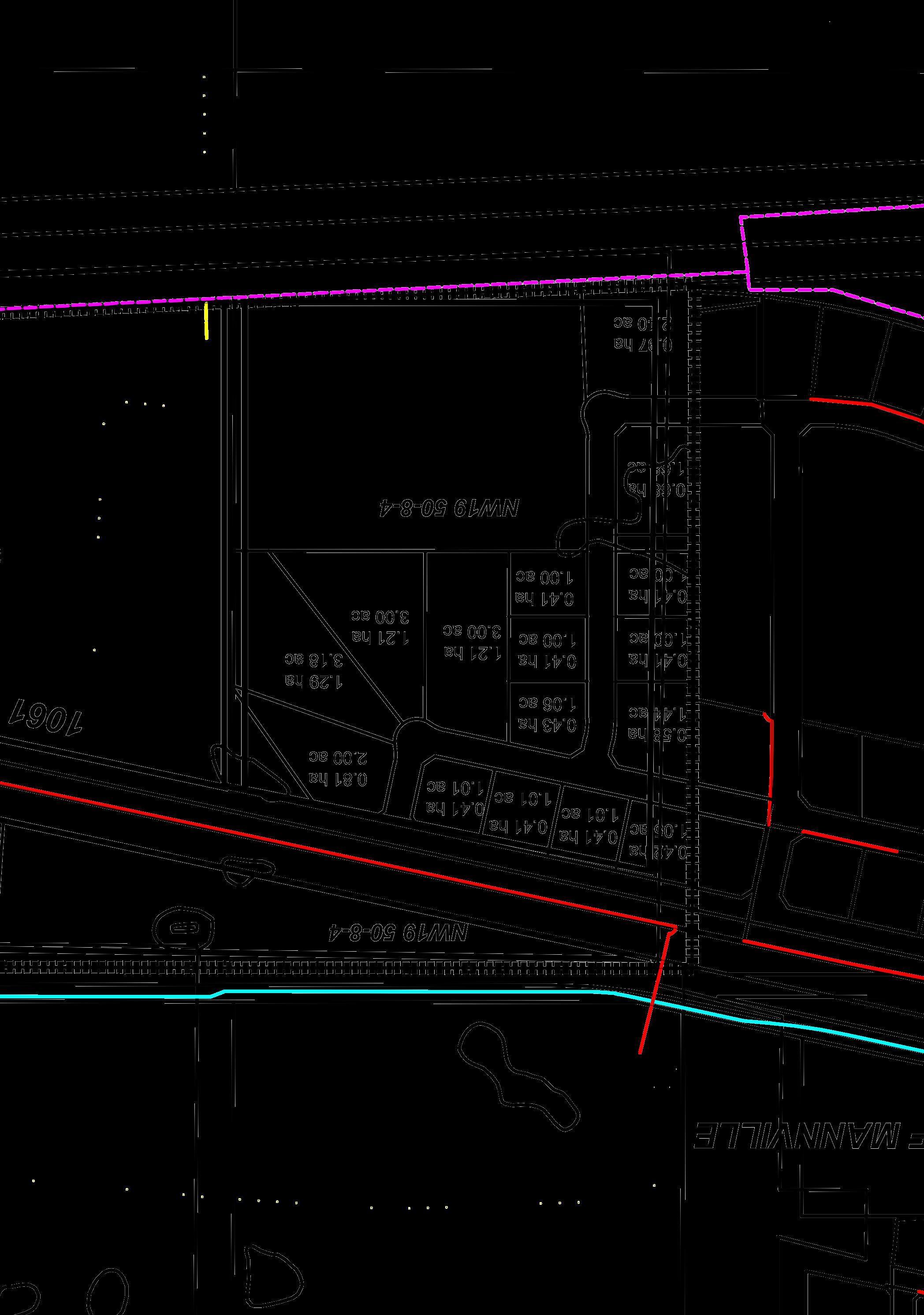
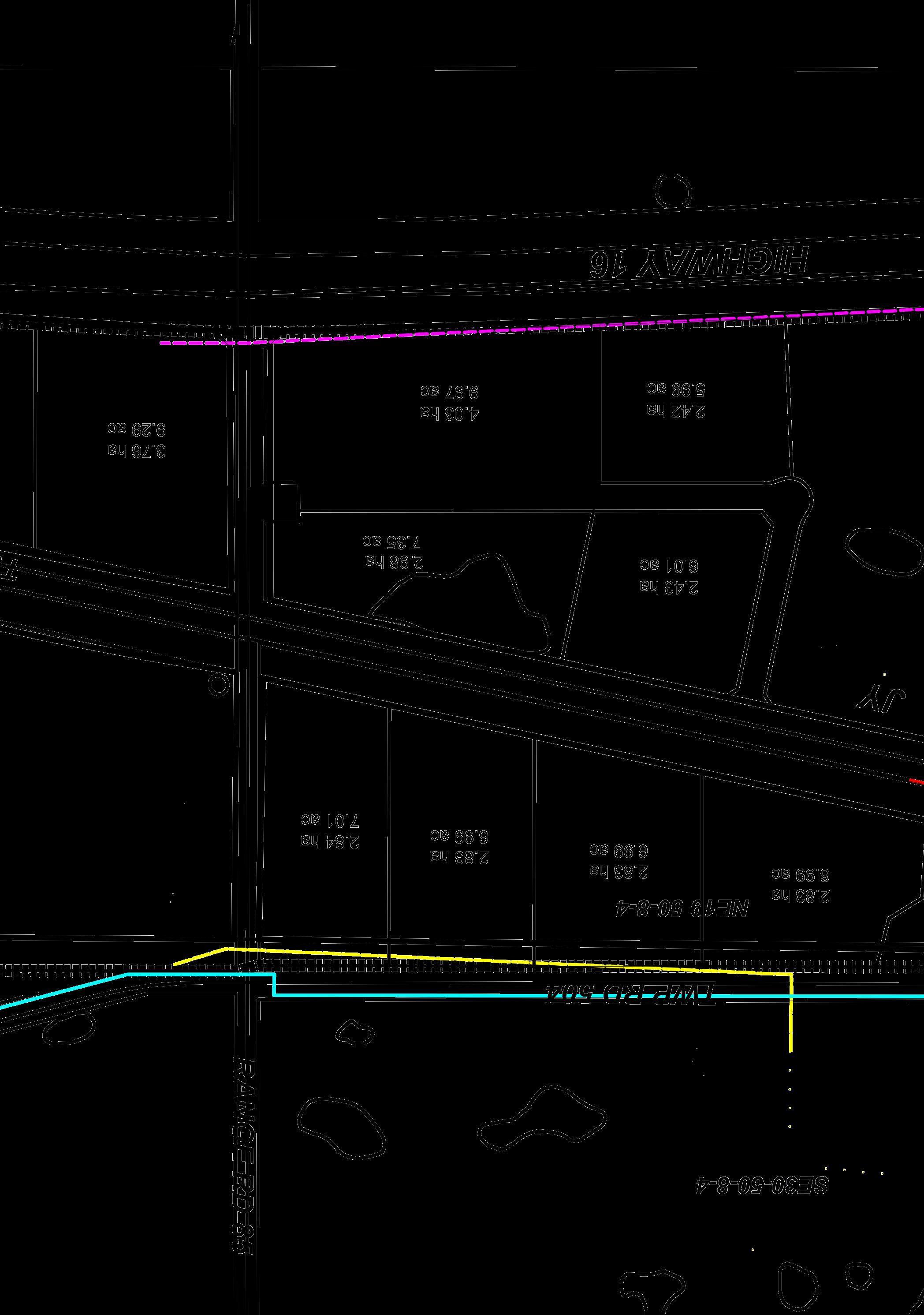
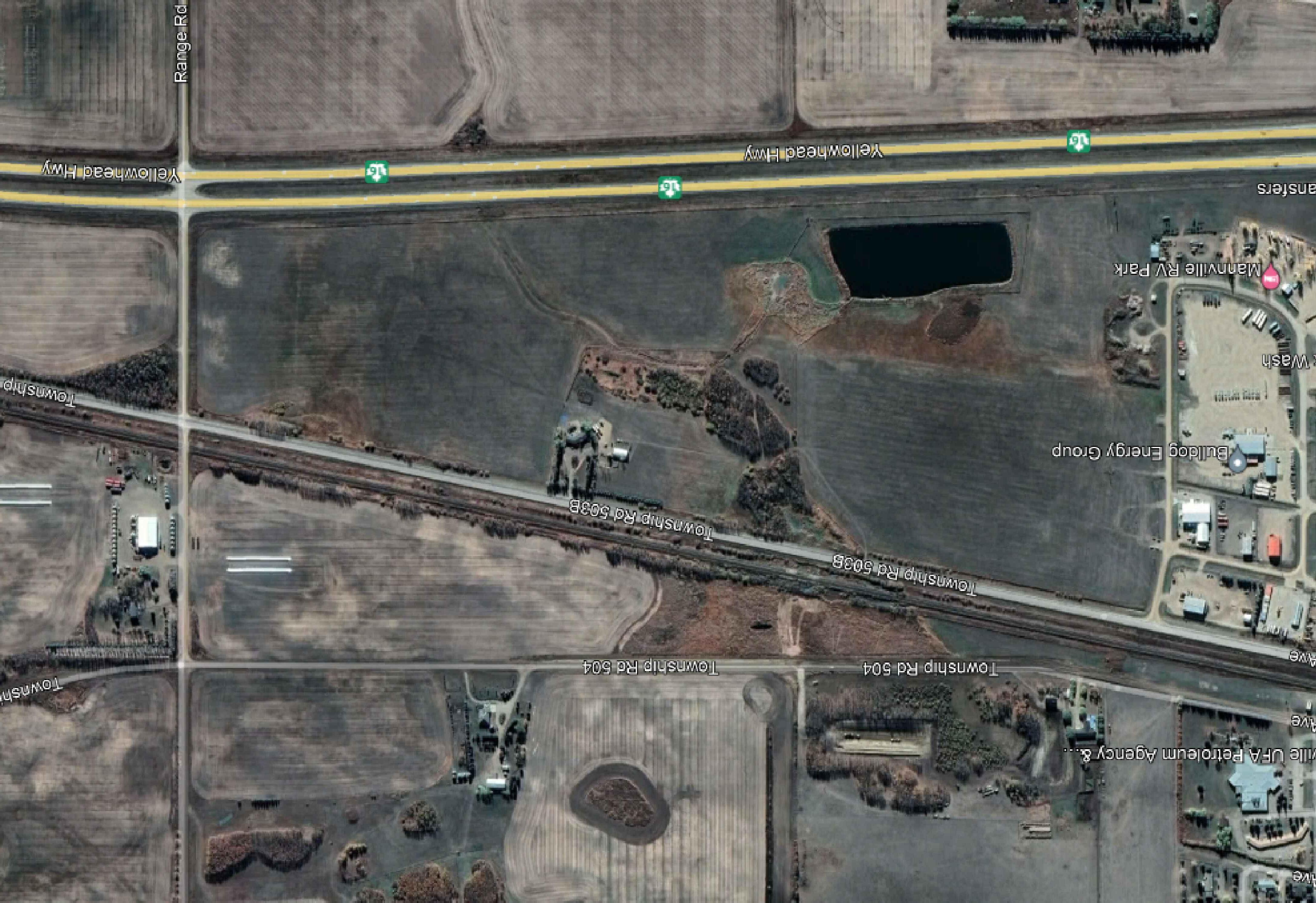


BH23-5 BH23-6 BH23-1
BH23-2
BH23-3
SolidEarth Geotechnical Inc. 4336 97 Street, Edmonton, AB, T6E 5R9 FIGURE No.: 1 April 2023 DATE: PROJECT No.: PG23-1691DATUM: DRAWN BY: SCALE: NTS MK DRAWING TITLE: PROJECT NAME: CLIENT: Proposed East Industrial Park ASP N1/2 of 19-50-8 W4M Village of Mannville, Alberta Project Layout and Borehole Location Plan REVISION No.: 1 BH23-02 BoreholeLocation Legend
BH23-4
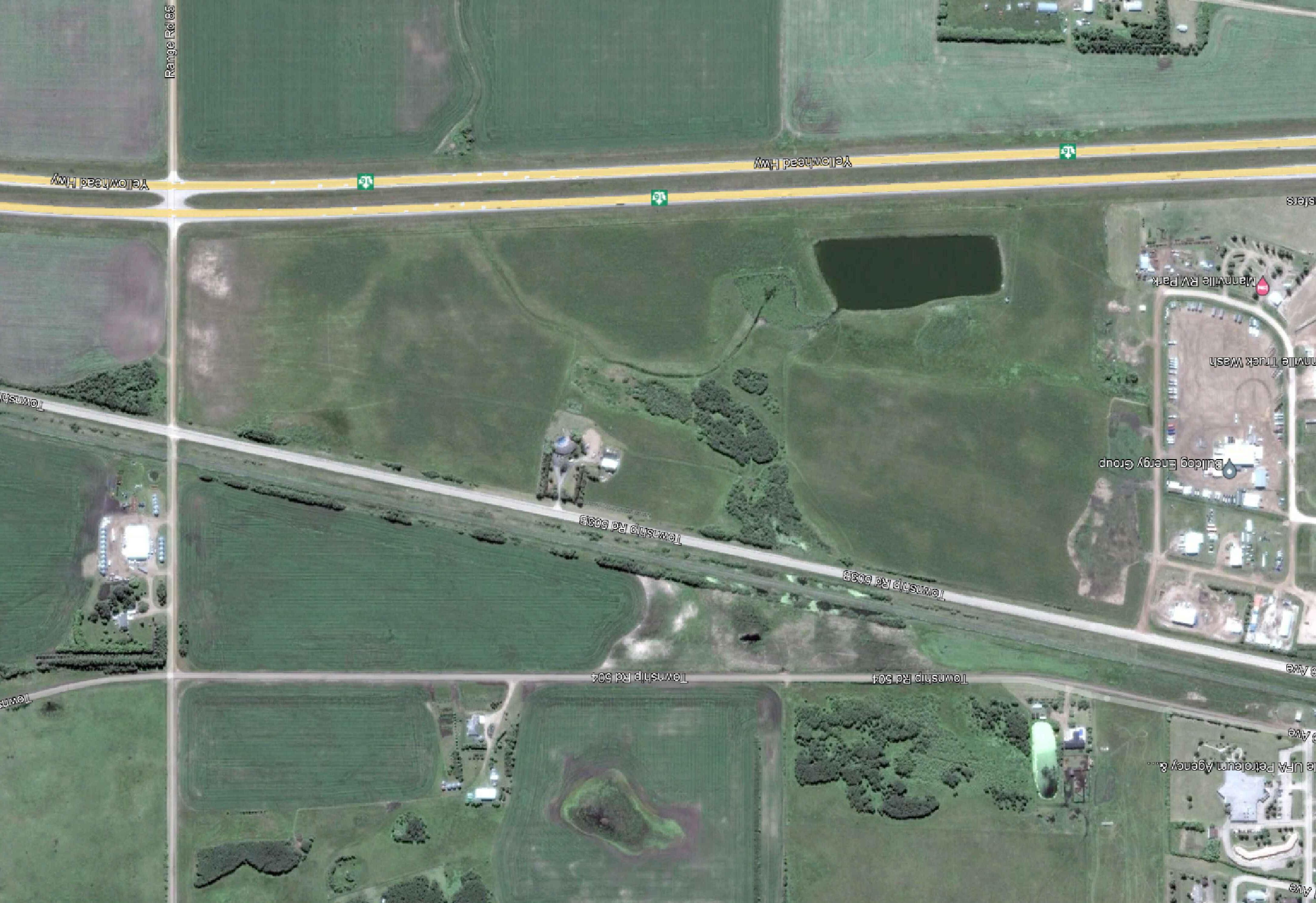
Building SolidEarth Geotechnical Inc. 4336 97 Street, Edmonton, AB, T6E 5R9 FIGURE No.: 2 April 2023 DATE: PROJECT No.: PG23-1691DATUM: DRAWN BY: SCALE: NTS MK DRAWING TITLE: PROJECT NAME: CLIENT: Proposed East Industrial Park ASP N1/2 of 19-50-8 W4M Village of Mannville, Alberta 2016 Aerial Photograph of the Site REVISION No.: 1
StudyArea Residential
StudyArea
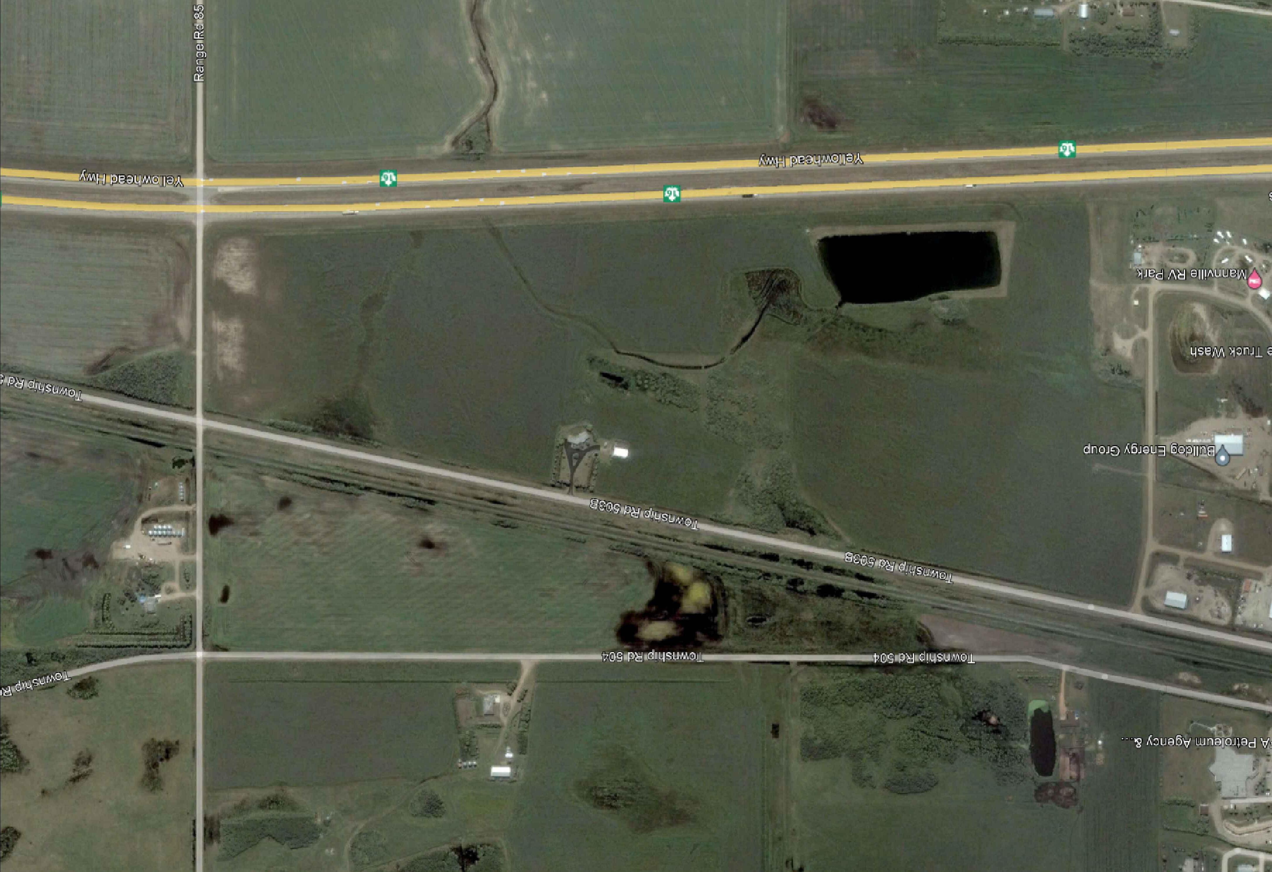
Residential Building
SolidEarth Geotechnical Inc. 4336 97 Street, Edmonton, AB, T6E 5R9 FIGURE No.: 3 April 2023 DATE: PROJECT No.: PG23-1691DATUM: DRAWN BY: SCALE: NTS MK DRAWING TITLE: PROJECT NAME: CLIENT: Proposed East Industrial Park ASP N1/2 of 19-50-8 W4M Village of Mannville, Alberta 2007 Aerial Photograph of the Site REVISION No.: 1
StudyArea
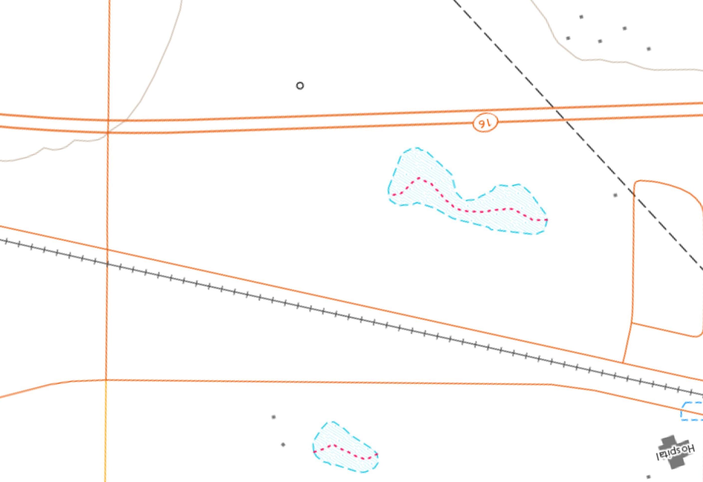
630m 630m Elev:620m Elev:620m SolidEarth Geotechnical Inc. 4336 97 Street, Edmonton, AB, T6E 5R9 FIGURE No.: 4 April 2023 DATE: PROJECT No.: PG23-1691DATUM: DRAWN BY: SCALE: NTS MK DRAWING TITLE: PROJECT NAME: CLIENT: Proposed East Industrial Park ASP N1/2 of 19-50-8 W4M Village of Mannville, Alberta Atlas of CanadaToporama Maps REVISION No.: 1
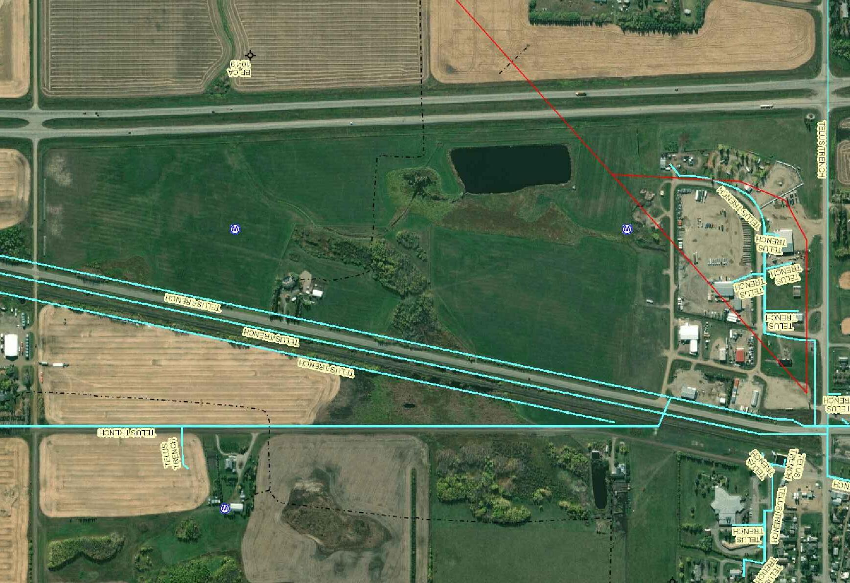
MincoGas Pipeline MincoGas Pipeline WaterWell (57.61m) WaterWell (60.96m) ATCOGas Pipeline SolidEarth Geotechnical Inc. 4336 97 Street, Edmonton, AB, T6E 5R9 FIGURE No.: 5 April 2023 DATE: PROJECT No.: PG23-1691DATUM: DRAWN BY: SCALE: NTS MK DRAWING TITLE: PROJECT NAME: CLIENT: Proposed East Industrial Park ASP N1/2 of 19-50-8 W4M Village of Mannville, Alberta Approximate Project Layout and Oil and Gas Infrastructure REVISION No.: 1
Geotechnical Investigation
Proposed East Industrial Subdivision ASP Within Portions of N ½ 19-50-8 W4M Village of Mannville Alberta
A
Site Photographs Taken During the Field Investigation
Appendix
Geotechnical Investigation
Proposed East Industrial Subdivision ASP
Within Portions of N ½ 19-50-8 W4M Village of Mannville Alberta
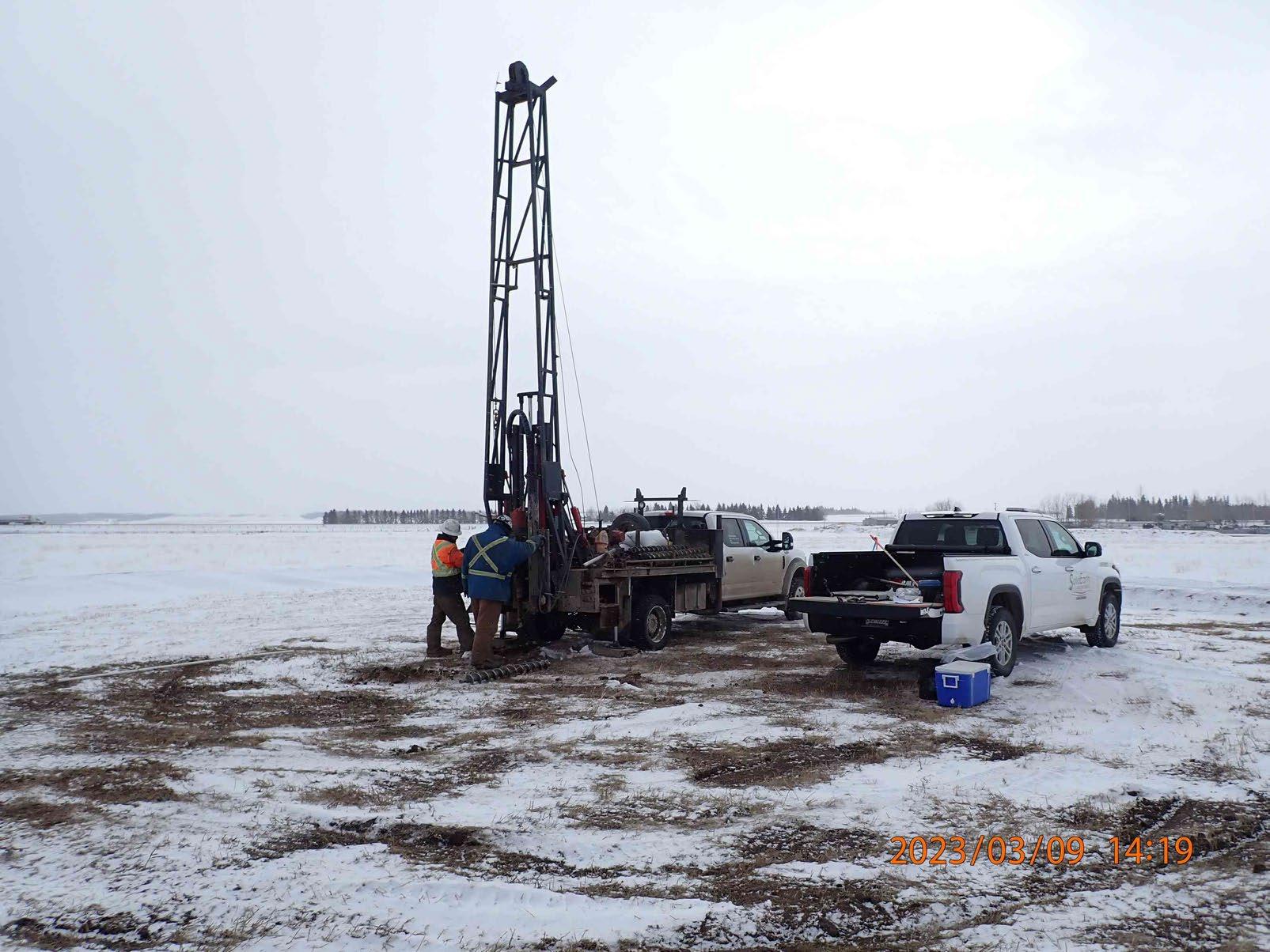
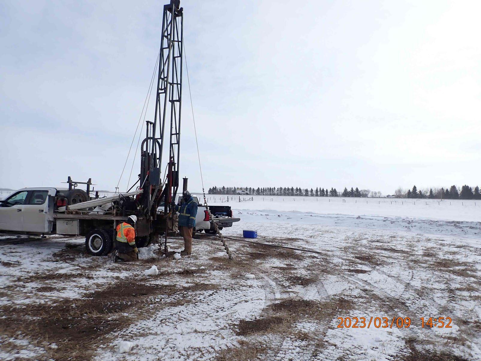 Photograph 1: Looking south towards BH23-1
Photograph 2: Looking south towards BH23-2
Photograph 1: Looking south towards BH23-1
Photograph 2: Looking south towards BH23-2
Geotechnical Investigation
Proposed East Industrial Subdivision ASP Within Portions of N ½ 19-50-8 W4M Village of Mannville Alberta
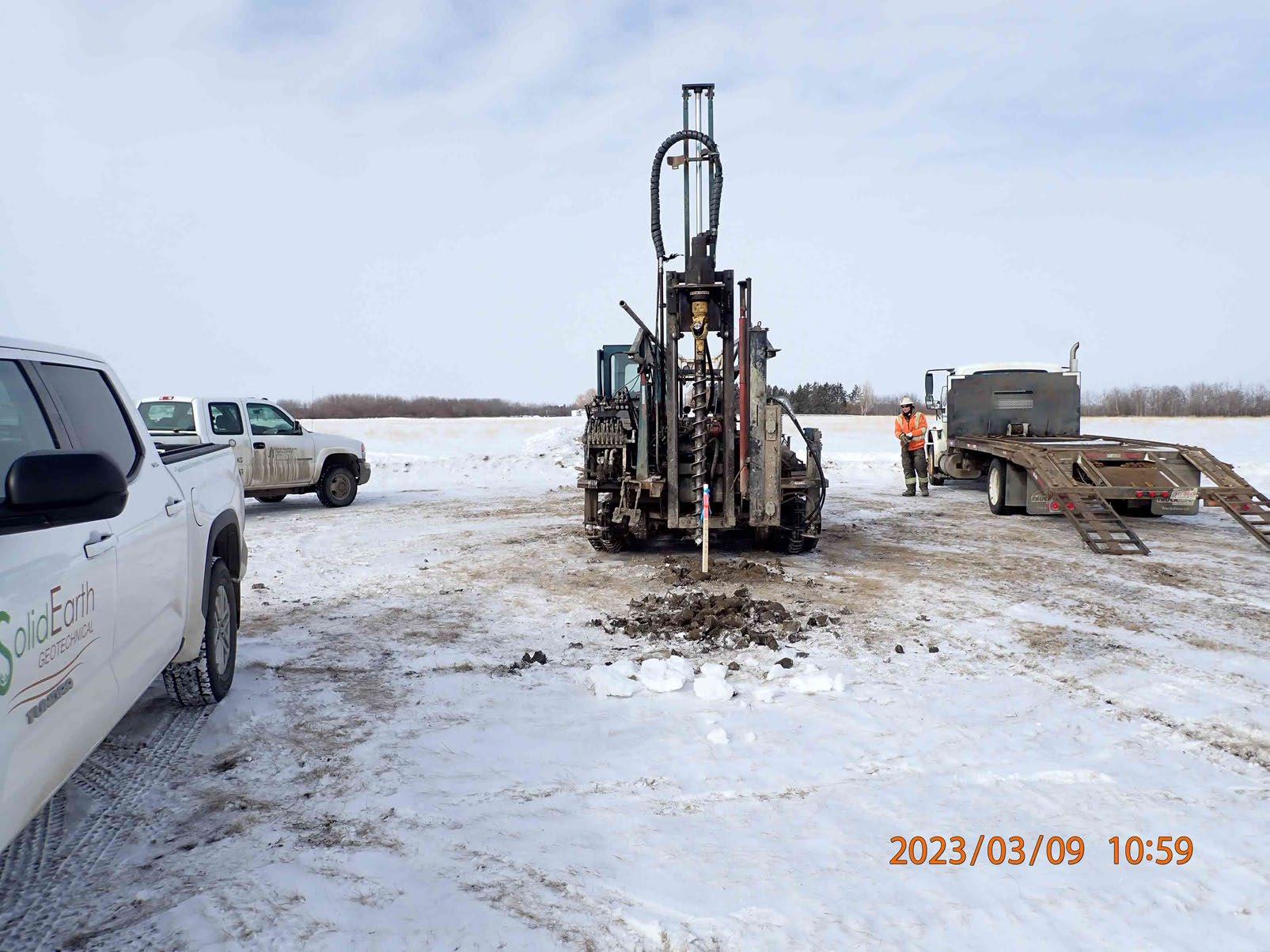 Photograph 3: Looking east towards BH23-3
Photograph 4: Looking west towards BH23-4
Photograph 3: Looking east towards BH23-3
Photograph 4: Looking west towards BH23-4
Geotechnical Investigation
Proposed East Industrial Subdivision ASP Within Portions of N ½ 19-50-8 W4M Village of Mannville Alberta
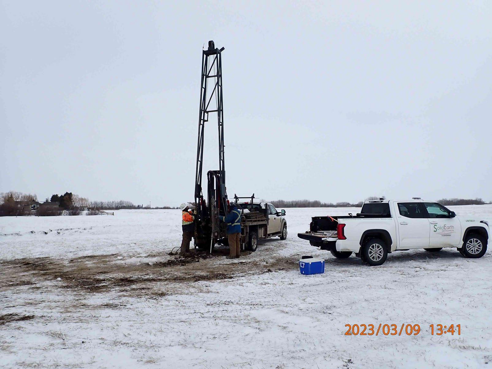
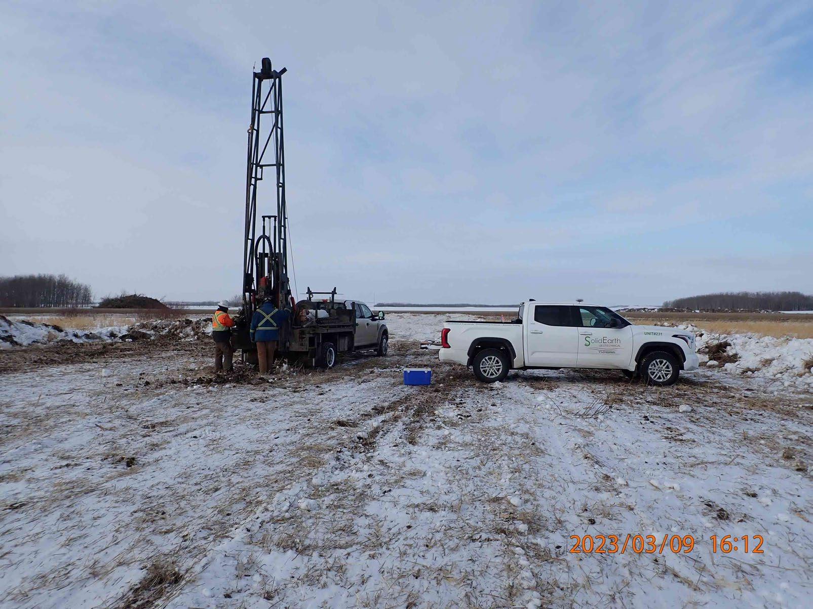 Photograph 5: Looking north towards BH23-5
Photograph 6: Looking south towards BH23-6
Photograph 5: Looking north towards BH23-5
Photograph 6: Looking south towards BH23-6
Geotechnical Investigation
Proposed East Industrial Subdivision ASP Within Portions of N ½ 19-50-8 W4M Village of Mannville Alberta
B
Borehole Logs
Explanation of Terms and Symbols
Appendix
ProjectName:ProposedEastIndustrialParkASP
ClientName:BarEngineeringCo.Ltd.
Site:N1/219-50-8W4M,VillageofMannville,Alberta Northing:5909450Easting:488826
Borehole#:BH22-1
Project#: PG23-1691
LoggedBy:HC/ReviewedBy:KJ CompletionDate:23-3-9 Driller:EvergreenDrillingLtd.
Elevation:623.7m Sample SymbolSample #

DrillMethod:150mmSolidStemAuger Page1of1
AdditionalData& Notes
CULTIVATEDSOIL(~50mmthick)
SAND,finetomediumgrained,somegravel,tracesilt, traceclay,poorlygraded,brown,damp
CLAY(TILL),andsand,andsilt,tracegravel,medium plastic,grey-brown,tracesandpockets,traceoxides,moist -verystiff
Frozento~0.8mbelow groundsurface
GrainSizeDistribution:
Gravel:12%
Sand:76%
Fines:12%
-becominggrey-brown
-becominggrey
COMPLETIONDEPTH:5.8mbelowgroundsurface
AtCompletion
Noccumulationofwaterorsloughuponcompletion. Slottedstandpipeinstalledto5.8mbelowgroundsurface. Boreholebackfilledwithdrillcuttingsandbentoniteplugs.
LiquidLimit:35%
PlasticLimit:11%
GrainSizeDistribution:
Gravel:1%
Sand:40%
Silt:39%
Clay:20%
WaterLevel: Dryon20March,2023
20 18 17 1 2 3 4 5 6 7 8 OR SP CI 0 9 Material Description 20406080 SPTNValue Soil Symbol Depth (m) 1 2 3 4 5 6 7 8 623 622 621 620 619 618 617 616 615 Elevation (m)
M.C.Liquid 20406080 Plastic Z:\PROJECTS\GEOTECHNICAL PROJECTS\2023\PG23-1691-BAR-MANVILLE EAST INDUSTRIAL SUB\FIELD AND LABWORK\PG23-1691.GPJ 23-04-04 03:08 PM (SEG-FINAL) 100200300400 PocketPen(kPa) Sand PeaGravelGroutSlough DrillCuttings Bentonite
NoRecoveryGrab SampleSPT Test(N) Core Split-Pen ShelbyTube
BackfillSymbol SampleSymbol
SPT (N-Value) USCS SLOTTEDPIEZOMETER
ProjectName:ProposedEastIndustrialParkASP
ClientName:BarEngineeringCo.Ltd.
Site:N1/219-50-8W4M,VillageofMannville,Alberta Northing:5909131Easting:488813
Borehole#:BH22-2
Project#: PG23-1691
LoggedBy:HC/ReviewedBy:KJ
CompletionDate:23-3-9 Driller:EvergreenDrillingLtd.
Elevation:624.2m Sample SymbolSample # SPT (N-Value)
CULTIVATEDSOIL(~75mmThick)
CLAY(TILL),andsand,andsilt,tracegravel,lowto mediumplastic,brown,tracesandpockets,traceoxides, moist -verystiff -becominggrey-brown -traceseepage
COMPLETIONDEPTH:6.6mbelowgroundsurface
AtCompletion
Accumulationofwaterat6.6mbelowgroundsurface. Noaccumulationofsloughuponcompletion. Slottedstandpipeinstalledto6.4mbelowgroundsurface. Boreholebackfilledwithdrillcuttingsandbentoniteplugs.
SampleSymbol
DrillMethod:150mmSolidStemAuger Page1of1 BackfillSymbol
Frozento~0.8mbelow groundsurface
WaterLevel: 4.0mbelowexistingground surfaceon20March,2023
16 24 17 1 2 3 4 5 6 7 8 9 OR CI/CL 0 9 Material Description 20406080 SPTNValue Soil Symbol Depth (m) 1 2 3 4 5 6 7 8 624 623 622 621 620 619 618 617 616 Elevation (m) AdditionalData& Notes M.C.Liquid 20406080 Plastic Z:\PROJECTS\GEOTECHNICAL PROJECTS\2023\PG23-1691-BAR-MANVILLE EAST INDUSTRIAL SUB\FIELD AND LABWORK\PG23-1691.GPJ 23-04-04 03:08 PM (SEG-FINAL) 100200300400 PocketPen(kPa) Sand PeaGravelGroutSlough DrillCuttings Bentonite
NoRecoveryGrab SampleSPT Test(N) Core Split-Pen ShelbyTube
USCS SLOTTEDPIEZOMETER
ProjectName:ProposedEastIndustrialParkASP
ClientName:BarEngineeringCo.Ltd.
Site:N1/219-50-8W4M,VillageofMannville,Alberta Northing:5909318Easting:489492
Elevation:626.1m
SampleSymbol
BackfillSymbol
Borehole#:BH22-3
Project#: PG23-1691
LoggedBy:HC/ReviewedBy:KJ
CompletionDate:23-3-9 Driller:EvergreenDrillingLtd.
DrillMethod:150mmSolidStemAuger Page1of1
SymbolSample
CULTIVATEDSOIL(~50mmThick)
SAND,mediumtocoarsegrained,andgravel,tracesilt, traceclay,poorlygraded,brown,traceoxides,moist CLAY(TILL),andsand,andsilt,tracegravel,lowto mediumplastic,brown,tracesandseams,traceoxides, moist
COMPLETIONDEPTH:7.3mbelowgroundsurface
AtCompletion
Noaccumulationofwaterorsloughuponcompletion. Slottedstandpipeinstalledto7.3mbelowgroundsurface. Boreholebackfilledwithdrillcuttingsandbentoniteplugs.
Frozento~0.5mbelow groundsurface
-verystiff -becominggrey -becomingstiff -becomingverystiff
LiquidLimit:31% PlasticLimit:10% WaterLevel: Dryon20March,2023 24 21 12 21 1 2 3 4 5 6 7 8 9 10 OR SP CI/CL 0 9 Material Description 20406080 SPTNValue Soil Symbol Depth (m) 1 2 3 4 5 6 7 8 626 625 624 623 622 621 620 619 618 Elevation (m) AdditionalData& Notes M.C.Liquid 20406080 Plastic Z:\PROJECTS\GEOTECHNICAL PROJECTS\2023\PG23-1691-BAR-MANVILLE EAST INDUSTRIAL SUB\FIELD AND LABWORK\PG23-1691.GPJ 23-04-04 03:08 PM (SEG-FINAL) 100200300400 PocketPen(kPa) Sand PeaGravelGroutSlough DrillCuttings Bentonite
NoRecoveryGrab SampleSPT Test(N) Core Split-Pen ShelbyTube
USCS SLOTTEDPIEZOMETER
Sample
# SPT (N-Value)
ProjectName:ProposedEastIndustrialParkASP
ClientName:BarEngineeringCo.Ltd.
Site:N1/219-50-8W4M,VillageofMannville,Alberta Northing:5909209Easting:489716
Elevation:625m
SampleSymbol
BackfillSymbol
Borehole#:BH22-4
Project#: PG23-1691
LoggedBy:HC/ReviewedBy:KJ
CompletionDate:23-3-9 Driller:EvergreenDrillingLtd.
DrillMethod:150mmSolidStemAuger Page1of1
CULTIVATEDSOIL(~75mmThick)
SAND,finetomediumgrained,somegravel,tracesilt, traceclay,poorlygraded,brown,damp
CLAY(TILL),andsand,andsilt,tracegravel,stiff,lowto mediumplastic,brown,tracesand/siltseams,tracesand pockets,traceoxides,moist
Frozento~0.5mbelow groundsurface
-becomingverystiff
-becominggrey-brown
COMPLETIONDEPTH:7.3mbelowgroundsurface
AtCompletion
Noaccumulationofwaterorsloughuponcompletion. Slottedstandpipeinstalledto7.3mbelowgroundsurface. Boreholebackfilledwithdrillcuttingsandbentoniteplugs.
WaterLevel: Dryon20March,2023
-becominggrey -becominghard
11 18 18 20 35 1 2 3 4 5 6 7 8 9 10 OR SP CI/CL 0 9 Material Description 20406080 SPTNValue Soil Symbol Depth (m) 1 2 3 4 5 6 7 8 624 623 622 621 620 619 618 617 Elevation (m) AdditionalData& Notes M.C.Liquid 20406080 Plastic Z:\PROJECTS\GEOTECHNICAL PROJECTS\2023\PG23-1691-BAR-MANVILLE EAST INDUSTRIAL SUB\FIELD AND LABWORK\PG23-1691.GPJ 23-04-04 03:08 PM (SEG-FINAL) 100200300400 PocketPen(kPa) Sand PeaGravelGroutSlough DrillCuttings Bentonite
NoRecoveryGrab SampleSPT Test(N) Core Split-Pen ShelbyTube
# SPT (N-Value) USCS SLOTTEDPIEZOMETER
Sample SymbolSample
ProjectName:ProposedEastIndustrialParkASP
ClientName:BarEngineeringCo.Ltd.
Site:N1/219-50-8W4M,VillageofMannville,Alberta Northing:5909126Easting:489379
Borehole#:BH22-5
Project#: PG23-1691
LoggedBy:HC/ReviewedBy:KJ
CompletionDate:23-3-9 Driller:EvergreenDrillingLtd.
Elevation:625.3m Sample SymbolSample
CULTIVATEDSOIL(~50mmThick)
CLAY(TILL),andsand,andsilt,tracegravel,stiff,lowto mediumplastic,brown,traceoxides,moist -becomingverystiff -becominggrey-brown
COMPLETIONDEPTH:7.3mbelowgroundsurface
AtCompletion
Noaccumulationofwaterorsloughuponcompletion. Slottedstandpipeinstalledto7.3mbelowgroundsurface. Boreholebackfilledwithdrillcuttingsandbentoniteplugs.
SampleSymbol
DrillMethod:150mmSolidStemAuger Page1of1 BackfillSymbol
AdditionalData& Notes
Frozento~0.8mbelow groundsurface
LiquidLimit:31% PlasticLimit:11%
WaterLevel: Dryon20March,2023 11 18 18 20 35 1 2 3 4 5 6 7 8 9 10 OR CI/CL 0 9 Material Description 20406080 SPTNValue Soil Symbol Depth (m) 1 2 3 4 5 6 7 8 625 624 623 622 621 620 619 618 617 Elevation (m)
M.C.Liquid 20406080 Plastic Z:\PROJECTS\GEOTECHNICAL PROJECTS\2023\PG23-1691-BAR-MANVILLE EAST INDUSTRIAL SUB\FIELD AND LABWORK\PG23-1691.GPJ 23-04-04 03:08 PM (SEG-FINAL) 100200300400 PocketPen(kPa) Sand PeaGravelGroutSlough DrillCuttings Bentonite
NoRecoveryGrab SampleSPT Test(N) Core Split-Pen ShelbyTube
SPT (N-Value) USCS SLOTTEDPIEZOMETER
#
ProjectName:ProposedEastIndustrialParkASP
ClientName:BarEngineeringCo.Ltd.
Site:N1/219-50-8W4M,VillageofMannville,Alberta Northing:5909583Easting:489248
Elevation:626.6m
SampleSymbol
BackfillSymbol
Borehole#:BH22-6
Project#: PG23-1691
LoggedBy:HC/ReviewedBy:KJ
CompletionDate:23-3-9 Driller:EvergreenDrillingLtd.
DrillMethod:150mmSolidStemAuger Page1of1
TOPSOIL(~12.5mmThick)
SAND,mediumgrained,somegravel,tracesilt,trace clay,poorlygraded,brown,verymoist
CLAY(TILL),andsand,andsilt,tracegravel,firm, mediumplastic,brown,traceoxides,moist
Frozento~0.5mbelow groundsurface
-becomingmoist
-becomingverystiff
-becomingtraceseepage
-becominggrey-brown
COMPLETIONDEPTH:7.3mbelowgroundsurface
AtCompletion
Accumulationofwaterat7.3mbelowgroundsurface. Noaccumulationofsloughuponcompletion. Slottedstandpipeinstalledto7.3mbelowgroundsurface. Boreholebackfilledwithdrillcuttingsandbentoniteplugs.
WaterLevel: 1.9mbelowexistingground surfaceon20March,2023
-becominggrey
-becominghard
5 17 18 19 31 1 2 3 4 5 6 7 8 9 10 OR SP CI 0 9 Material Description 20406080 SPTNValue Soil Symbol Depth (m) 1 2 3 4 5 6 7 8 626 625 624 623 622 621 620 619 618 Elevation (m) AdditionalData& Notes M.C.Liquid 20406080 Plastic Z:\PROJECTS\GEOTECHNICAL PROJECTS\2023\PG23-1691-BAR-MANVILLE EAST INDUSTRIAL SUB\FIELD AND LABWORK\PG23-1691.GPJ 23-04-04 03:08 PM (SEG-FINAL) 100200300400 PocketPen(kPa) Sand PeaGravelGroutSlough DrillCuttings Bentonite
NoRecoveryGrab SampleSPT Test(N) Core Split-Pen ShelbyTube
SPT (N-Value) USCS SLOTTEDPIEZOMETER
Sample SymbolSample #

EXPLANATION OF TERMS & SYMBOLS
The terms and symbols used on the borehole logs to summarize the results of the field investigation and laboratory testing are described on the following two pages.
1. VISUAL TEXTURAL CLASSIFICATION ON MINERAL SOILS
CLASSIFICATION
Boulders
Silt 0.002 mm to 0.075 mm
Non-plastic particles, not visible to naked eye
Clay < 0.002 mm Plastic particles, not visible to naked eye
2. TERMS FOR CONSISTENCY & DENSITY OF SOILS
Cohesionless Soils
DESCRIPTIVE
Cohesive Soils
* SPT “N” Values – Refers to the number of blows by a 63.5 kg hammer dropped 760 mm to drive a 50 mm diameter split spoon sampler for a distance of 300 mm after an initial penetration of 150 mm.
3. SYMBOLS USED ON BOREHOLE LOGS
SYMBOL DESCRIPTION
N(■) Standard Penetration Test (CSA A119 1-60) SO4 Concentration of Water-Soluble Sulphate
Nd Dynamic Cone Penetration Test Cu Undrained Shear Strength
pp (♦) Pocket Penetrometer Strength ɣ Unit Weight of Soil or Rock
qu Unconfined Compressive Strength ɣd Dry Unit Weight of Soil or Rock
w (●) Natural Moisture Content (ASTM D2216)
wL Liquid Limit (ASTM D 4318)
wP Plastic Limit (ASTM D 4318)
IP Plastic Index
Density of Soil or Rock
Dry Density of Soil or Rock
Short-Term Water Level
Long-Term Water Level
SolidEarth Geotechnical Inc. www.solidearth.ca
APPARENT PARTICLE SIZE VISUAL IDENTIFICATION
> 200
> 200
75 mm to 200 mm 75 mm to 200 mm Gravel 4.75 mm to 75 mm 5 mm to 75 mm
0.075
Visible
mm
mm Cobbles
Sand
mm to 4.75 mm
particles to 5 mm
TERM APPROXIMATE SPT
VALUE Very Dense > 50 Dense 30 to 50 Compact 10 to 30 Loose 4 to 10 Very Loose < 4
“N”
TERM UNDRAINED SHEAR STRENGTH APPROXIMATE SPT “N” VALUE Hard >200 kPa > 30 Very Stiff 100 to 200 kPa 15 to 30 Stiff 50 to 100 kPa 8 to 15 Firm 25 to 50 kPa 4 to 8 Soft 10 to 25 kPa 2 to 4 Very Soft < 10 kPa < 2
DESCRIPTIVE
SYMBOL
DESCRIPTION
ρ
ρd
(MOR E THAN HALF BY WEIGHT LARGER THAN 75 µ m)
MAJOR DIVISION
GRAVELS
(MORE THAN HALF COARSE GRAINS LARGER THAN 4.75mm)
SANDS
(MORE THAN HALF COARSE GRAINS SMALLER THAN 4.75mm)
CLEAN GRAVELS
(LITTLE OR NO FINES) GW
GRAVELS
(WITH SOME FINES)
CLEAN SANDS
(LITTLE OR NO FINES)
SANDS
(WITH SOME FINES)
WELL GRADED GRAVELS AND GRAVELSAND MIXTURES, LITTLE OR NO FINES Cu = D60/D10 > 4 Cc = (D30)2/(D10 x D60) = 1 to 3
POORLY GRADED GRAVELS AND GRAVEL-SAND MIXTURES, LITTLE OR NO FINES NOT MEETING ABOVE REQUIREMENTS
SILTY GRAVELS, GRAVEL-SAND-SILT MIXTURES CONTENT OF FINES EXCEEDS
CLAYEY GRAVELS, GRAVEL-SANDCLAY MIXTURES
SW WELL GRADED SANDS, GRAVELLY SANDS, LITTLE OR NO FINES
LIMITS BELOW ‘A’ LINE Ip LESS THAN 4
Cu = D60/D10 > 6 Cc = (D30)2/(D10 x D60) = 1 to 3
SP POORLY GRADED SANDS, GRAVELLY SANDS, LITTLE OR NO FINES NOT MEETING ALL GRADATION REQUIREMENTS FOR SW
SM SILTY SANDS, SAND-SILT MIXTURES CONTENT OF FINES EXCEEDS 12%
SC CLAYEY SANDS, SAND-CLAY MIXTURES
ATTERBERG LIMITS BELOW ‘A’ LINE Ip LESS THAN 4
ATTERBERG LIMITS ABOVE ‘A’ LINE Ip MORE THAN 7 FINE GRAINED SOILS
(MOR E THAN HALF BY WEIGHT SMALLER THAN 75 µ m) SILTS
(BELOW ‘A’ LINE NEGLIGIBLE ORGANIC CONTENT)
CLAYS
(ABOVE ‘A’ LINE NEGLIGIBLE ORGANIC CONTENT)
ORGANIC SILTS & CLAYS
(BELOW ‘A’ LINE)
W L < 50 % ML
W L > 50 % MH
W L < 30 % CL
30 % < W L < 50 % CI
W L > 50 % CH
W L < 50 % OL
W L > 50 % OH
HIGHLY ORGANIC SOILS Pt
Soil Components
Component Size Range (mm) Descriptor % by Weight
Cobbles > 76
Gravel 76 to 4.75
Coarse 76 to 19
Fine 19 to 4.75
Sand 4.75 to 0.075
Coarse 4.75 to 2
Medium2 to 0.425
INORGANIC SILTS AND VERY FINE SANDS, ROCK FLOUR, SILTY SANDS OF SLIGHT PLASTICITY
INORGANIC SILTS, MICACEOUS OR DIATOMACEOUS FINE SANDY OR SILTY SOILS
INORGANIC CLAYS OF LOW PLASTICITY, GRAVELLY, SANDY, OR SILTY CLAYS, LEAN CLAYS
INORGANIC CLAYS OR MEDIUM PLASTICITY, SILTY CLAYS
INORGANIC CLAYS OF HIGH PLASTICITY, FAT CLAYS
ORGANIC SILTS AND ORGANIC SILTY CLAYS OF LOW PLASTICITY
ORGANIC CLAYS OF HIGH PLASTICITY
CLASSIFICATION IS BASED UPON PLASTICITY CHART (SEE BELOW)
PEAT AND OTHER HIGHLY ORGANIC SOILS STRONG COLOUR OR ODOUR, AND OFTEN FIBROUS TEXTURE
Fine 0.425 to 0.075 -y, -ey 35 to 20 some 20 to 10 trace 10 to 1 > 35
Fines
(Silt or Clay) < 0.075 and
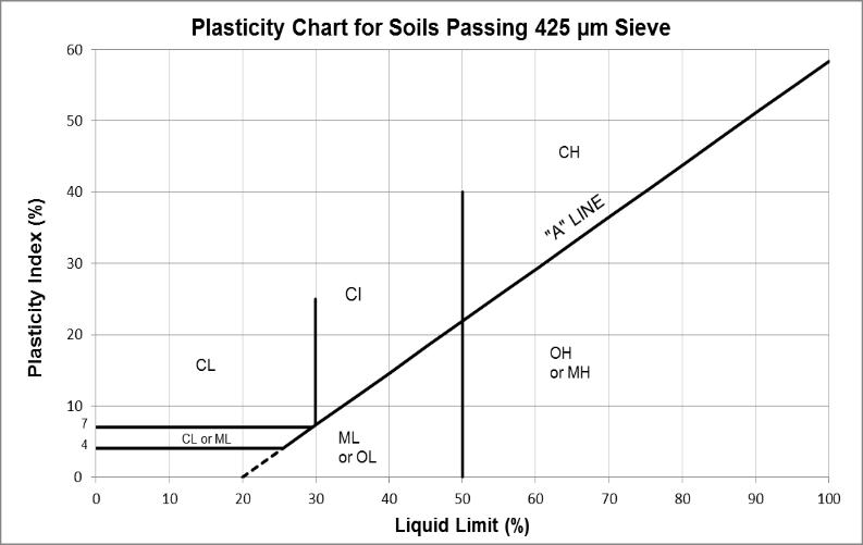
SolidEarth Geotechnical Inc. www.solidearth.ca
MODIFIED UNIFIED CLASSIFICATION SYSTEM FOR SOILS
GROUP SYMBOL TYPICAL DESCRIPTION LABORATORY CLASSIFICATION CRITERIA COARSE GRAINED SOILS
GP
ATTERBERG
GC
ATTERBERG LIMITS
LINE
MORE THAN
GM
12%
ABOVE ‘A’
Ip
7
BEDROCK
SEE REPORT DESCRIPTION
BR
Geotechnical Investigation
Proposed East Industrial Subdivision ASP Within Portions of N ½ 19-50-8 W4M Village of Mannville Alberta
Water Well Drilling Reports
Appendix C
Water Well Drilling Report
The driller supplies the data contained in this report. The Province disclaims responsibility for its accuracy. The information on this report will be retained in a public database.
Drilling Company Well ID Export to Excel GOWN ID
Province Country View in Metric
Measured from Boundary of GPS Coordinates in Decimal Degrees (NAD 83) Latitude Longitude Elevation
Measurement in Imperial How Location Obtained
How Elevation Obtained ft
Yield Test Summary
Measurement
Perforated by Machine
Proposed Well Use Type of Work Method of Drilling Observation New Well Rotary Drilling Information Formation Log Depth from ground level (ft) Water Bearing Lithology Description 23.00 Yellow Clay 44.00 Dark Clay 60.00 Brown Sand 92.00 Yellow Coarse Grained Sand 101.00 Sand 115.00 Yellow Sand 131.00 Sandy Gravel 135.00 Gray Shale 159.00 Dark Fine Grained Sandstone 164.00 Dark Medium Grained Sandstone 170.00 Brown Shale 178.00 Dark Sandstone 186.00 Dark Shale 187.00 Rocks 206.00 Black Sandstone 210.00 Gray Shale Measurement
Imperial Placed from Bottom at : Size OD : Diameter (in) From (ft) To (ft) 0.00 0.00 210.00 Well Completion Total Depth Drilled Finished Well Depth Start Date 210.00 ft 1998/10/28 End Date 1998/10/29 Borehole Surface Casing (if applicable) Well Casing/Liner Plastic Wall Thickness : Size OD : Wall Thickness : Top at : Bottom at : 0.00 0.000 0.00 2.50 0.276 0.00 190.00 Perforations From (ft) To (ft) Diameter or Slot Width(in) Slot Length (in) Hole or Slot Interval(in) 190.00 200.00 0.010 2.00
in
0.00
185.00 Amount Other Seals Type At (ft)
Type Stainless Steel Size OD : 2.00 From (ft) To (ft) Slot Size (in) 200.00 205.00 0.010 Attachment Top Fittings Bottom Fittings Coupler Attached To Casing Plug Measurement in Imperial Pack Type Grain Size Amount Artificial 20-40 5.00 in ft ft in in in ft in ft ft Bags
Annular Seal Bentonite Chips/Tablets
to
Screen
Test Date Water Removal Rate (igpm) Static Water Level (ft)
Printed on 3/21/2023 11:21:45 AM Page: 1 / 2 Certification No Company Name Name of Journeyman responsible
drilling/construction
well 1 MANNVILLE WATER WELL SERVICES LTD. UNKNOWN NA DRILLER
provided
signed 1998/11/27 292026 GoA
GIC
in Imperial Recommended Pump Rate igpm
for
of
Contractor Certification Copy of Well report
to owner Date approval holder
Well Tag No. Date Report Received
Well ID
Postal Code Town Address Owner Name T0B 2W0 P.O. BOX 180 MANNVILLE MANNVILLE, VILL OF
SEC TWP
Lot Block Plan NW 19 50
4
Well Identification and Location Location 1/4 or LSD
RGE W of MER
8
Additional Description
53.332095
-111.169062 ft from ft from Not Verified Not Obtained
Water Well Drilling Report
Measurement in Imperial
Distance From Top of Casing to Ground Level
Is Artesian Flow
Additional Information Is Flow Control Installed Describe Rate igpm
Recommended Pump Rate
Recommended Pump Intake Depth (From TOC)
Did you Encounter Saline Water (>4000
Remedial Action Taken
Additional Comments on Well
If water removal period was < 2 hours, explain why
Measurement in Imperial
Model (Output Rating)
Submitted to ESRD
igpm
Pump
Depth Type
ft
Installed
Make H.P.
Gas Depth Depth ft ft Well
ppm TDS)
Disinfected Upon Completion Geophysical Log Taken
Sample Collected for Potability Submitted to ESRD
in
ft
Electric
Diversion Date & Time Amount Taken Water Source
Diverted
ig
Water
for Drilling
Removal Test Date Start Time Static Water Level ft Type Removal Rate
From igpm ft
Yield Test Method of Water
Depth Withdrawn
Printed on 3/21/2023 11:21:45 AM Page: 2 / 2 Certification No Company Name Name of Journeyman responsible for drilling/construction of well 1 MANNVILLE WATER WELL SERVICES LTD. UNKNOWN NA DRILLER Contractor Certification Copy of Well report provided to owner Date approval holder signed 1998/11/27 292026 GoA Well Tag No. Date Report Received GIC Well ID
Measurement in Imperial Taken From Ground Level
Postal Code Town Address Owner Name T0B 2W0 P.O. BOX 180 MANNVILLE MANNVILLE, VILL OF Well Identification and Location Location 1/4 or LSD SEC TWP RGE W of MER Lot Block Plan NW 19 50 8 4 Additional Description
GPS Coordinates in Decimal Degrees (NAD 83) Latitude Longitude Elevation 53.332095 -111.169062 ft from ft from Not Verified Not Obtained
The driller supplies the data contained in this report. The Province disclaims responsibility for its accuracy. The information on this report will be retained in a public database.
Measured from Boundary of
How Location Obtained
How Elevation Obtained ft Province Country View in Metric
ID
Drilling Company Well ID Export to Excel GOWN
Water Well Drilling Report
The
Measurement in Imperial How Location Obtained
How Elevation Obtained ft
Yield Test Summary
Proposed Well Use Type of Work Method of Drilling Domestic & Stock New Well Rotary Drilling Information Formation Log Depth from ground level (ft) Water Bearing Lithology Description 9.00 Brown Sand 24.00 Yellow Clay 36.00 Brown Sand 42.00 Blue Clay 81.00 Brown Sand & Gravel 86.00 Gray Sand 94.00 Gray Shale 152.00 Gray Sandstone & Shale Ledges 171.00 Gray Sand 179.00 Gray Sand 181.00 Rocks 189.00 Gray Sand Measurement
Imperial Placed from Bottom at : Size OD : Diameter (in) From (ft) To (ft) 0.00 0.00 189.00 Well Completion Total Depth Drilled Finished Well Depth Start Date 189.00 ft 1987/02/27 End Date 1987/03/02 Borehole Surface Casing (if applicable) Well Casing/Liner Plastic Wall Thickness : Size OD : Wall Thickness : Top at : Bottom at : 5.00 0.240 182.00 0.00 0.000 0.00 0.00 Perforations From (ft) To (ft) Diameter or Slot Width(in) Slot Length (in) Hole or Slot Interval(in) Perforated by Annular Seal Pushed 0.00 to 0.00 Amount Other Seals Type At (ft) Screen Type Stainless Steel Size OD : 2.37 From (ft) To (ft) Slot Size (in) 184.00 189.00 0.020 Attachment Top Fittings Bottom Fittings Riser Pipe Attached To Riser Plug Measurement in Imperial Pack Type Grain Size Amount Gravel in ft ft in in in ft in ft ft
in
Test Date Water Removal Rate (igpm) Static Water Level (ft) 1987/03/02 10.00 65.00 Measurement in Imperial Recommended Pump Rate 10.00 igpm Printed on 3/21/2023 11:22:18 AM Page: 1 / 2 Certification No Company Name Name of Journeyman responsible for drilling/construction of well 1 FRED'S WATER WELL DRILLING LTD. UNKNOWN NA DRILLER
of Well report provided
owner Date approval holder signed 1987/03/30 250750 GoA Well Tag No.
Contractor Certification Copy
to
Date Report Received GIC Well ID
Postal Code Town Address Owner Name MANNVILLE GOLISH,
Well Identification and Location Location 1/4 or LSD SEC TWP RGE W of MER Lot Block Plan NE 19 50 8 4 Additional Description
driller supplies the data contained in this report. The Province disclaims responsibility for its accuracy. The information on this report will be retained in a public database.
JAMES
53.332095
Measured from Boundary of GPS Coordinates in Decimal Degrees (NAD 83) Latitude Longitude Elevation
-111.156980 ft from ft from Map Not Obtained
Province Country View in Metric
Export to Excel
Drilling Company Well ID
GOWN ID
Water Well Drilling Report
The driller supplies the data contained in this report. The Province disclaims responsibility for its accuracy. The information on this report will be retained in a public database.
Measurement
Measured from Boundary of
Distance From Top of Casing to Ground Level
Is Artesian Flow
Additional Information Is Flow Control Installed Describe Rate igpm Recommended Pump Rate
you
Remedial Action Taken
Additional Comments on Well
Measurement in Imperial ft
Model (Output Rating)
Submitted to ESRD
Sample Collected for Potability Submitted to ESRD
Measurement in Imperial Taken From Ground Level
If water removal period was < 2 hours, explain why
10.00
162.00 ft Pump Installed
Depth Type Make H.P. SUB .5
ppm
Gas Depth Depth ft ft Well
igpm Recommended Pump Intake Depth (From TOC)
Yes
Did
Encounter Saline Water (>4000
TDS)
Disinfected Upon Completion Geophysical Log Taken
MED SOFT WATER
in
Diversion Date & Time Amount Taken Water Source Water
ig
Pumping (ft) Elapsed Time Minutes:Sec Recovery (ft) Depth to water level Method of
Removal Test Date Pump & Air Start Time 12:00 AM Static Water Level 65.00 ft Type 115.00 Removal Rate Depth Withdrawn From 10.00 igpm ft 1987/03/02
Diverted for Drilling
Yield Test
Water
Printed on 3/21/2023 11:22:18 AM Page: 2 / 2 Certification No Company Name Name of Journeyman responsible for drilling/construction of well 1 FRED'S WATER WELL DRILLING LTD. UNKNOWN NA DRILLER Contractor
Copy
signed 1987/03/30 250750 GoA Well
No. Date
GIC Well ID
Certification
of Well report provided to owner Date approval holder
Tag
Report Received
Postal Code Town Address Owner Name MANNVILLE GOLISH, JAMES Well Identification
Location Location 1/4
LSD SEC TWP RGE W of MER Lot Block Plan NE 19 50 8 4 Additional Description
53.332095
and
or
GPS Coordinates in Decimal Degrees (NAD 83) Latitude Longitude Elevation
-111.156980 ft from ft from Map Not Obtained
View
Metric
Export to Excel GOWN
in Imperial How Location Obtained How Elevation Obtained ft Province Country
in
Drilling Company Well ID
ID
C Appendix C Lagoon Assessment
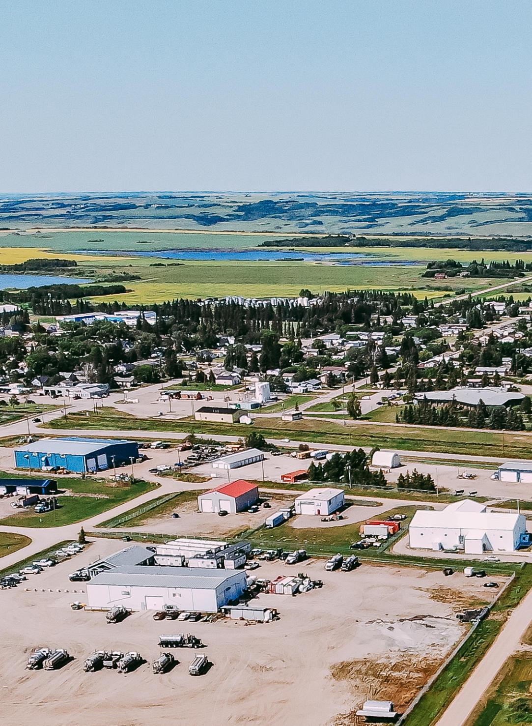
Does not form part of this Bylaw.
Prepared by: BAR Engineering
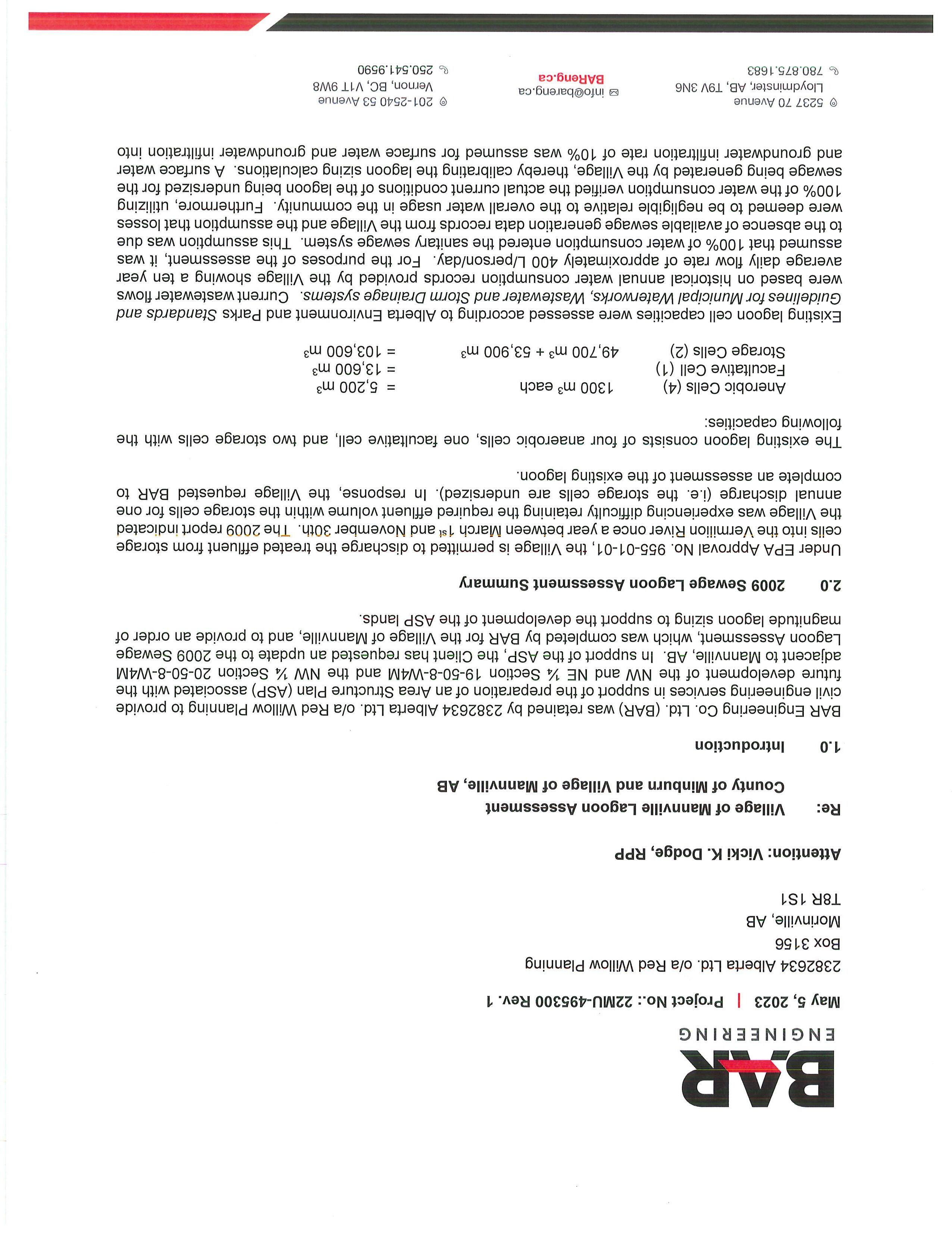
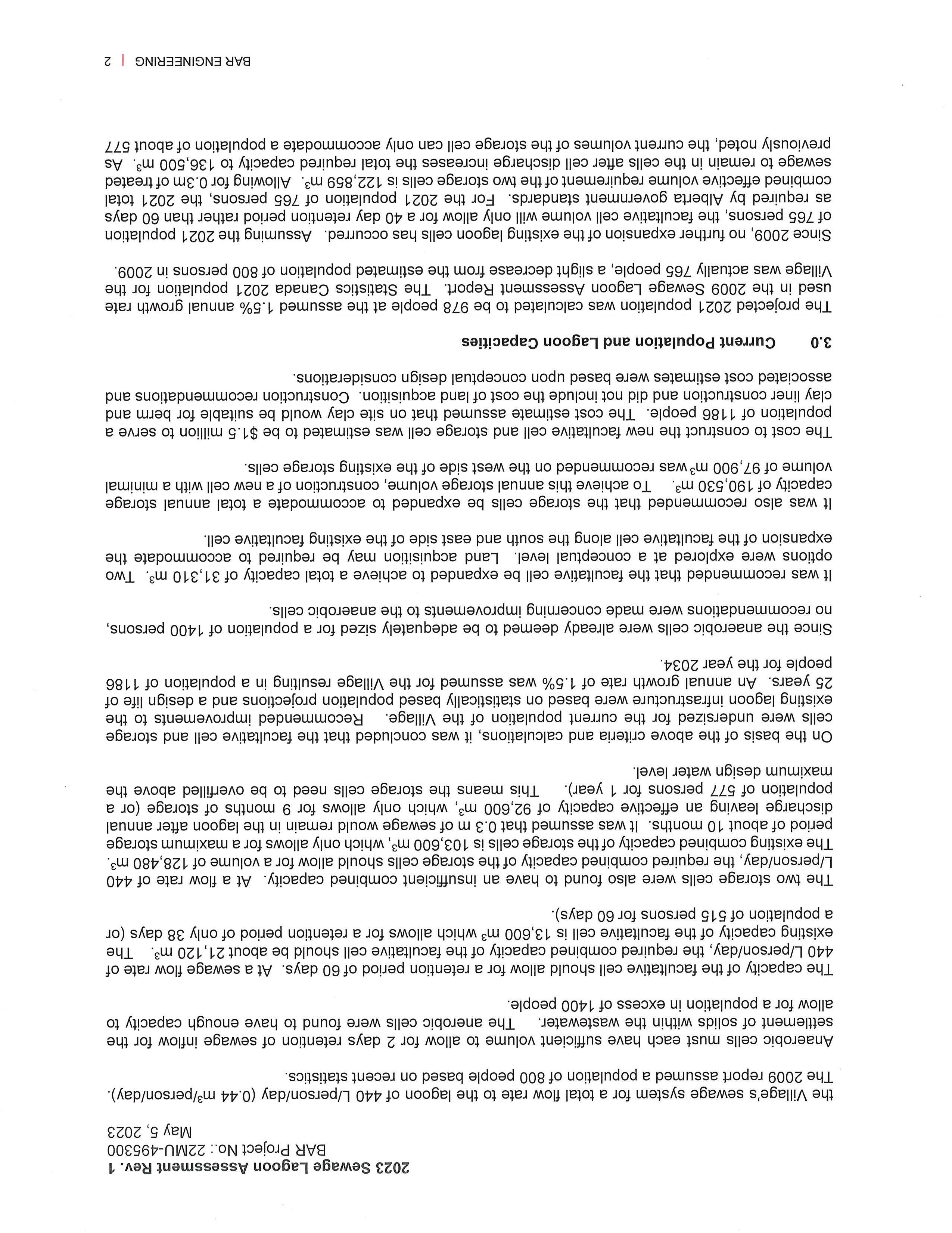
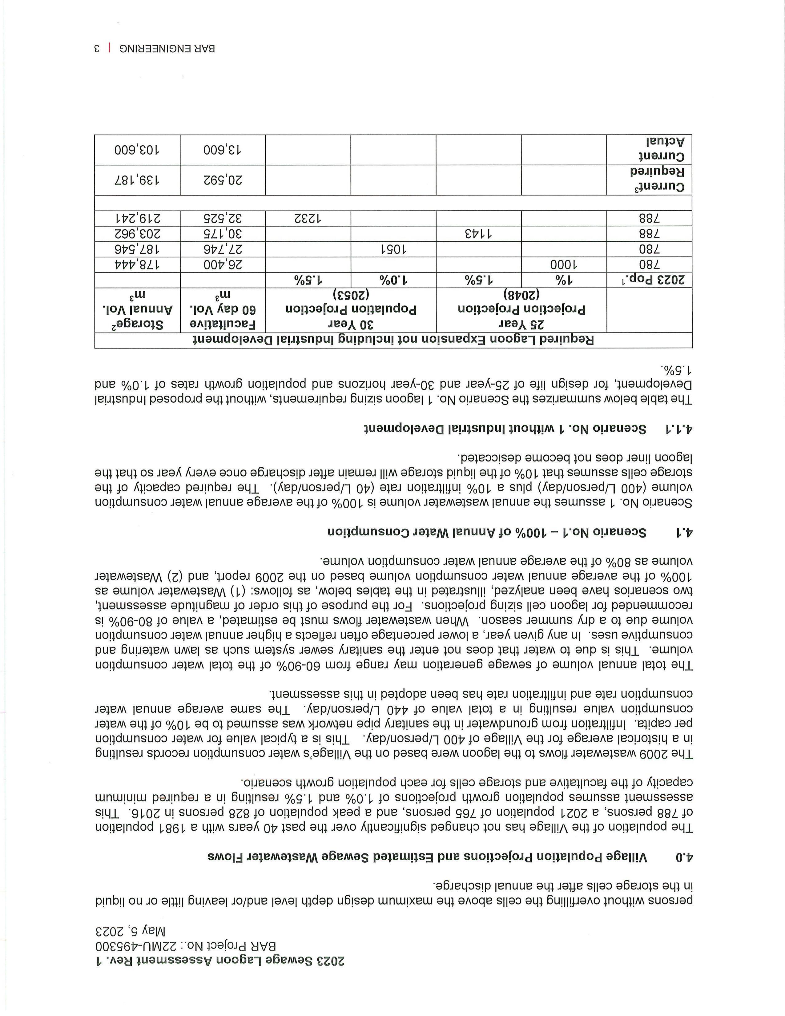
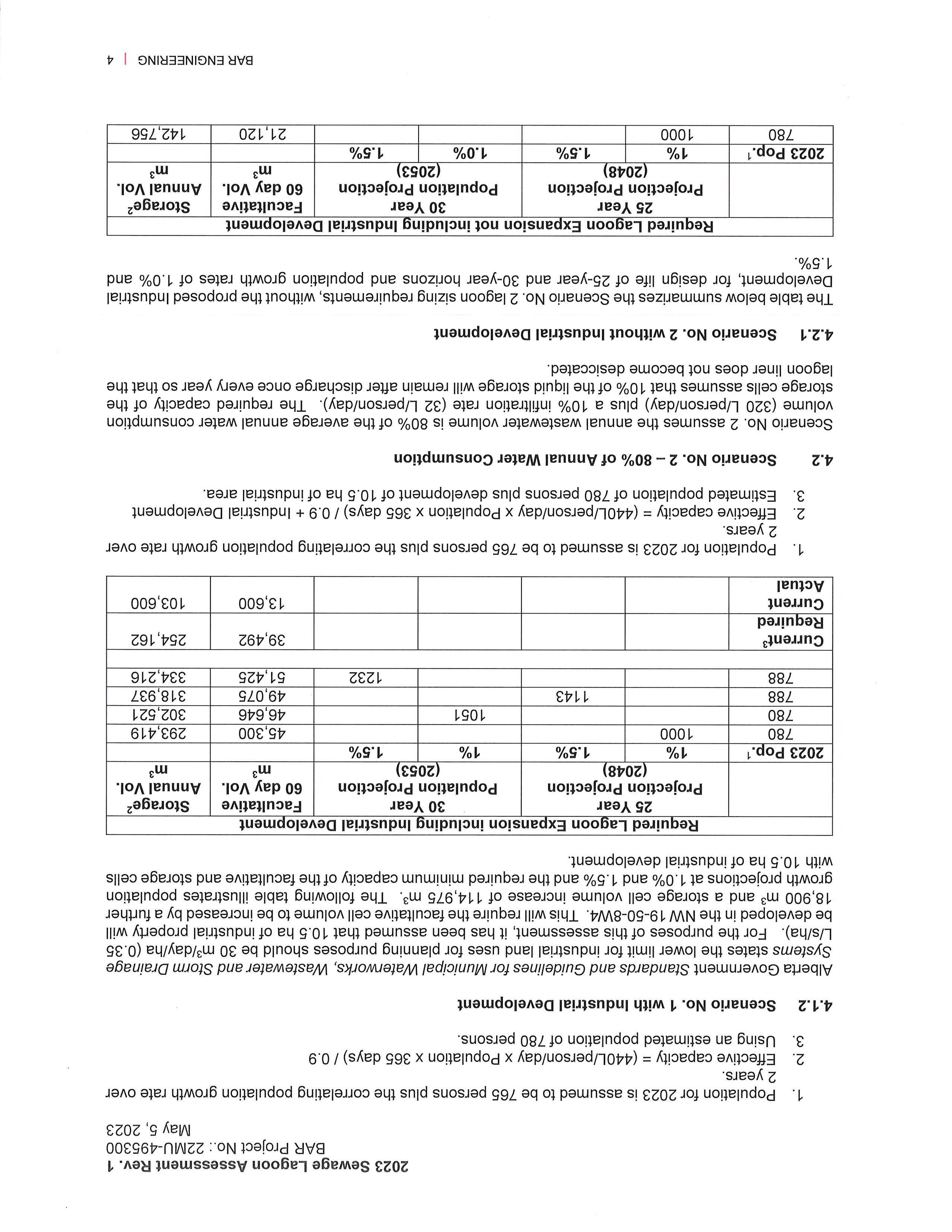
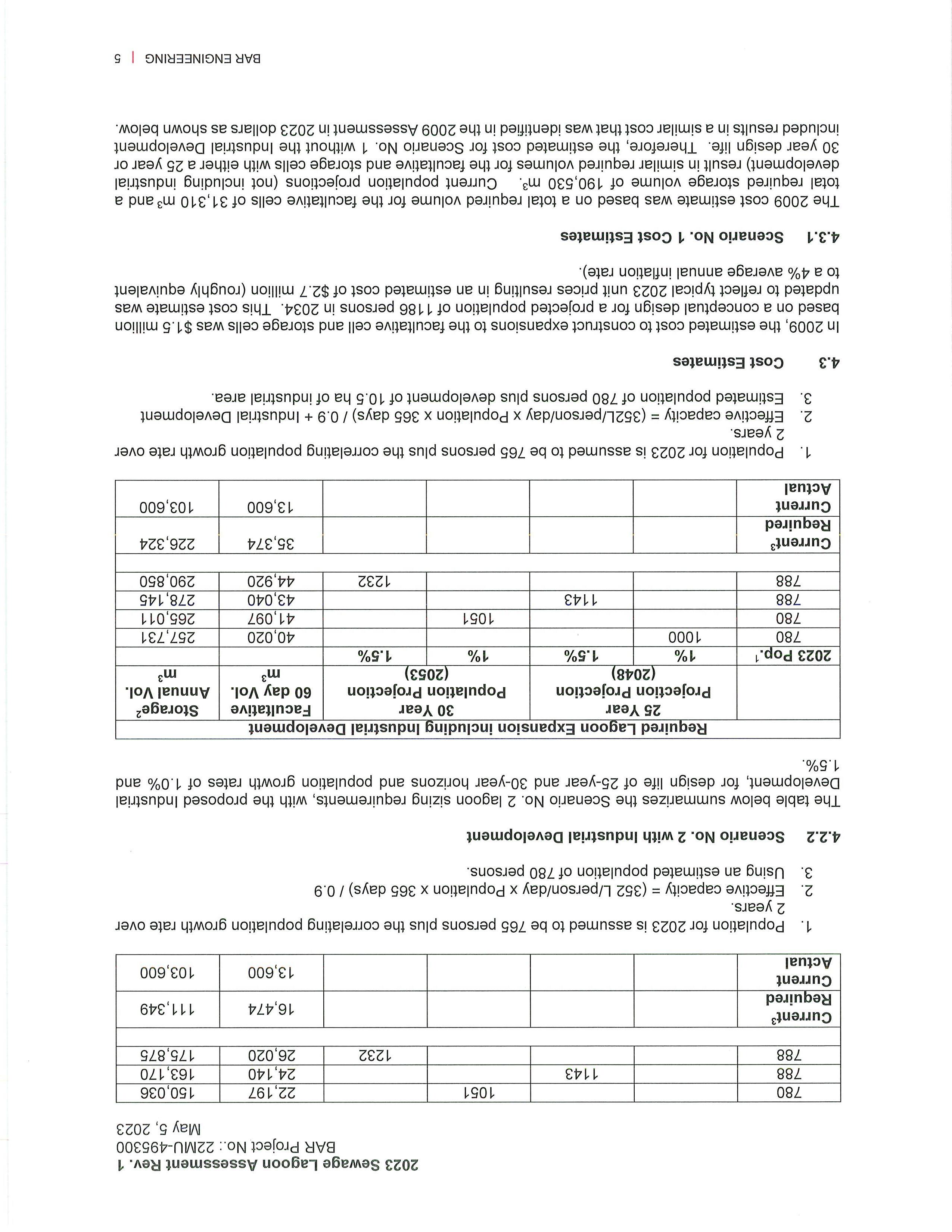
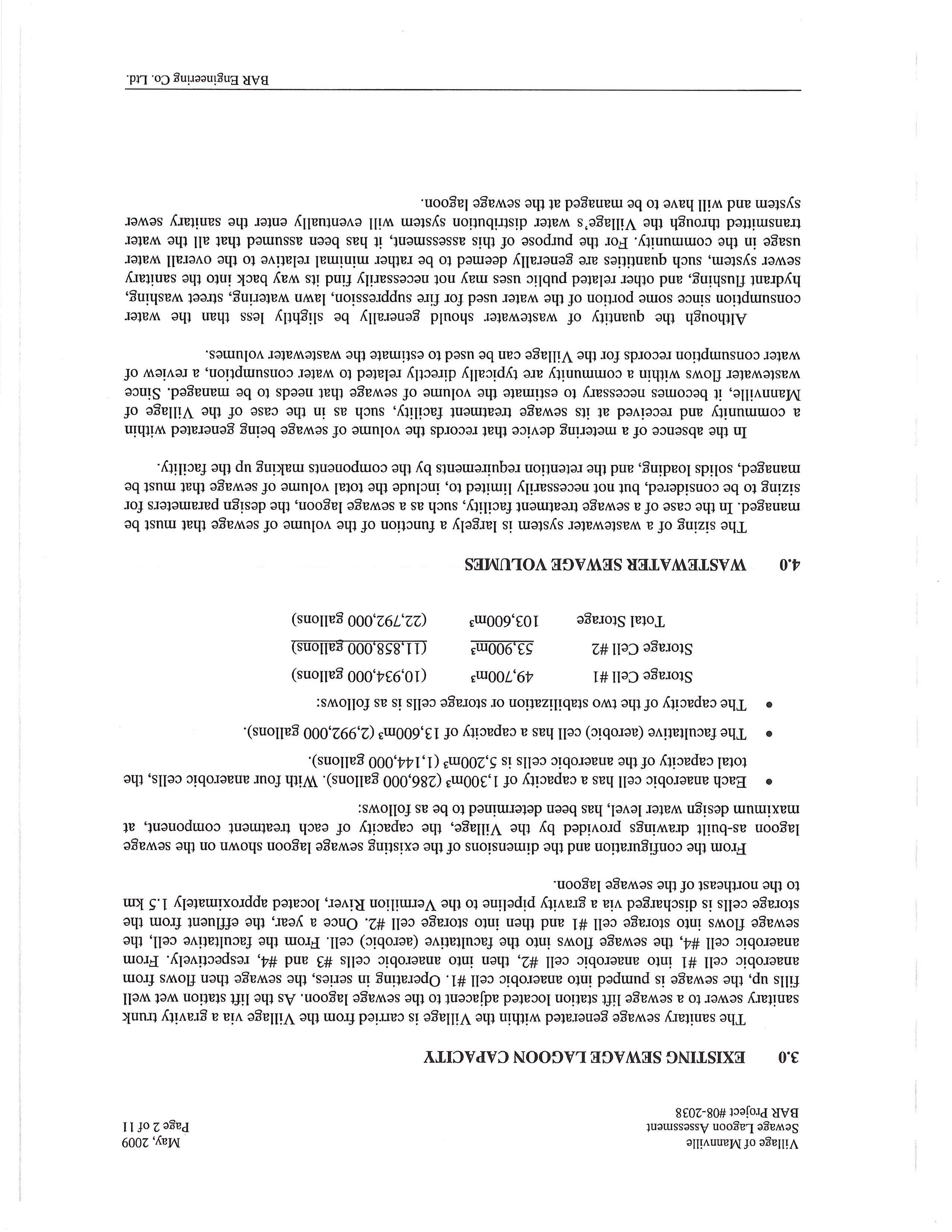
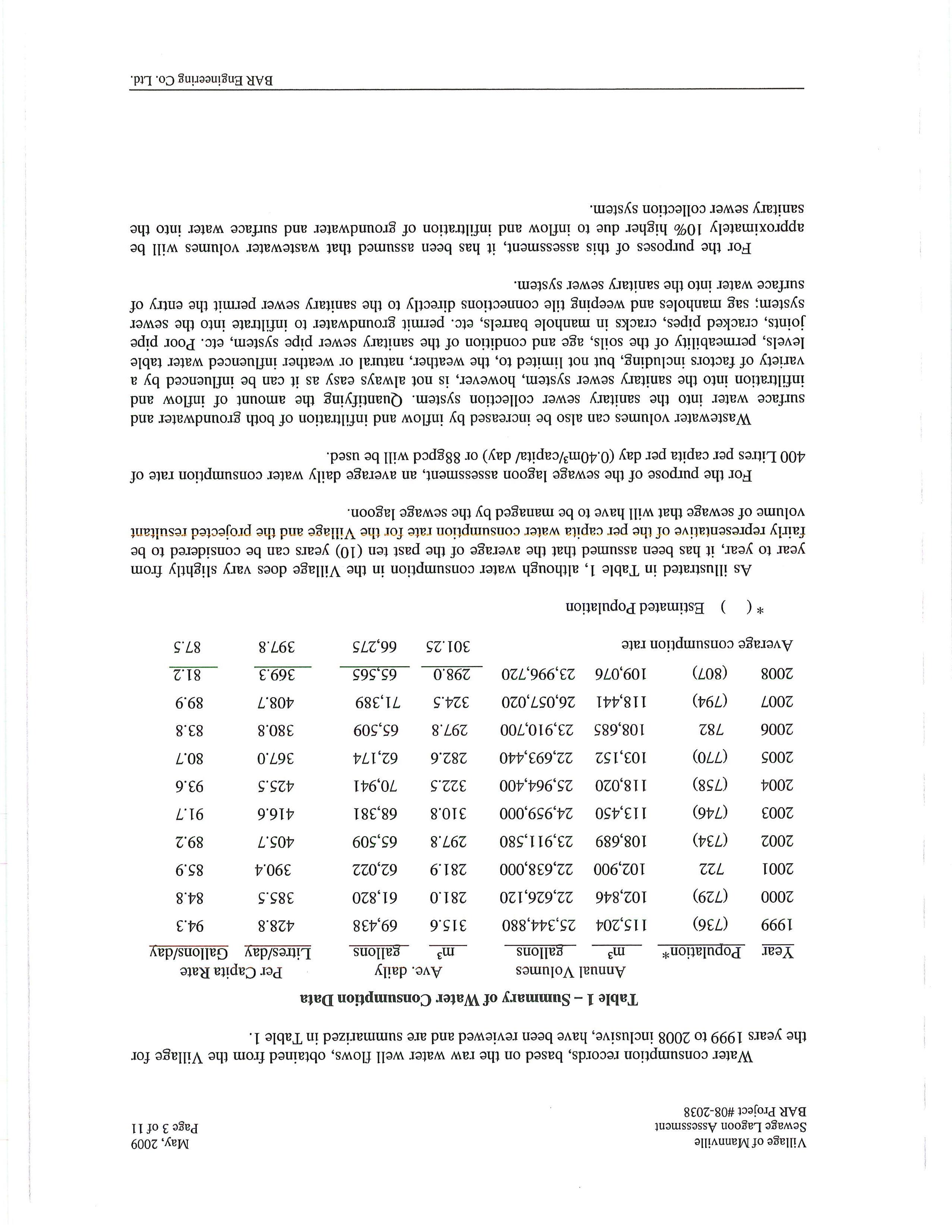
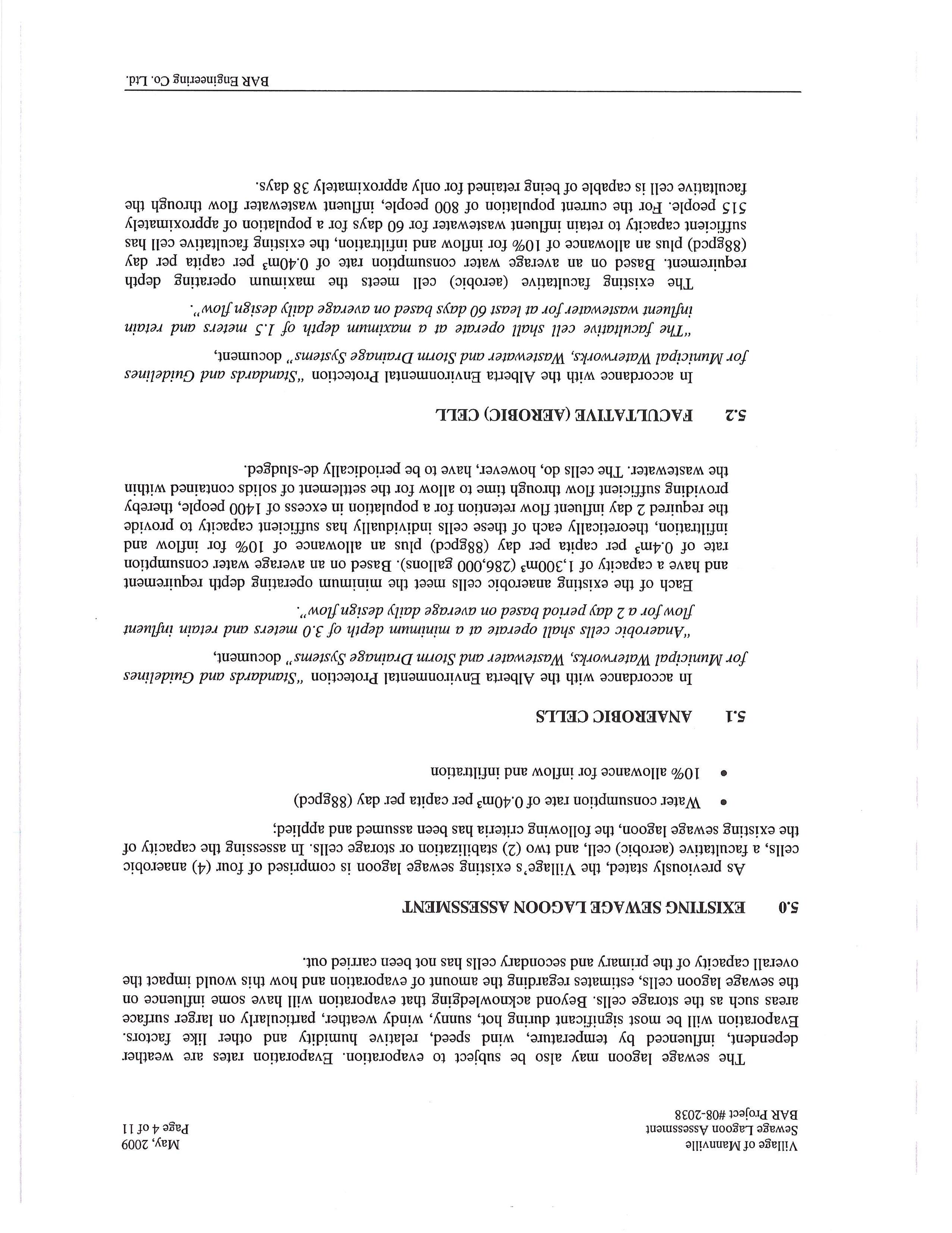
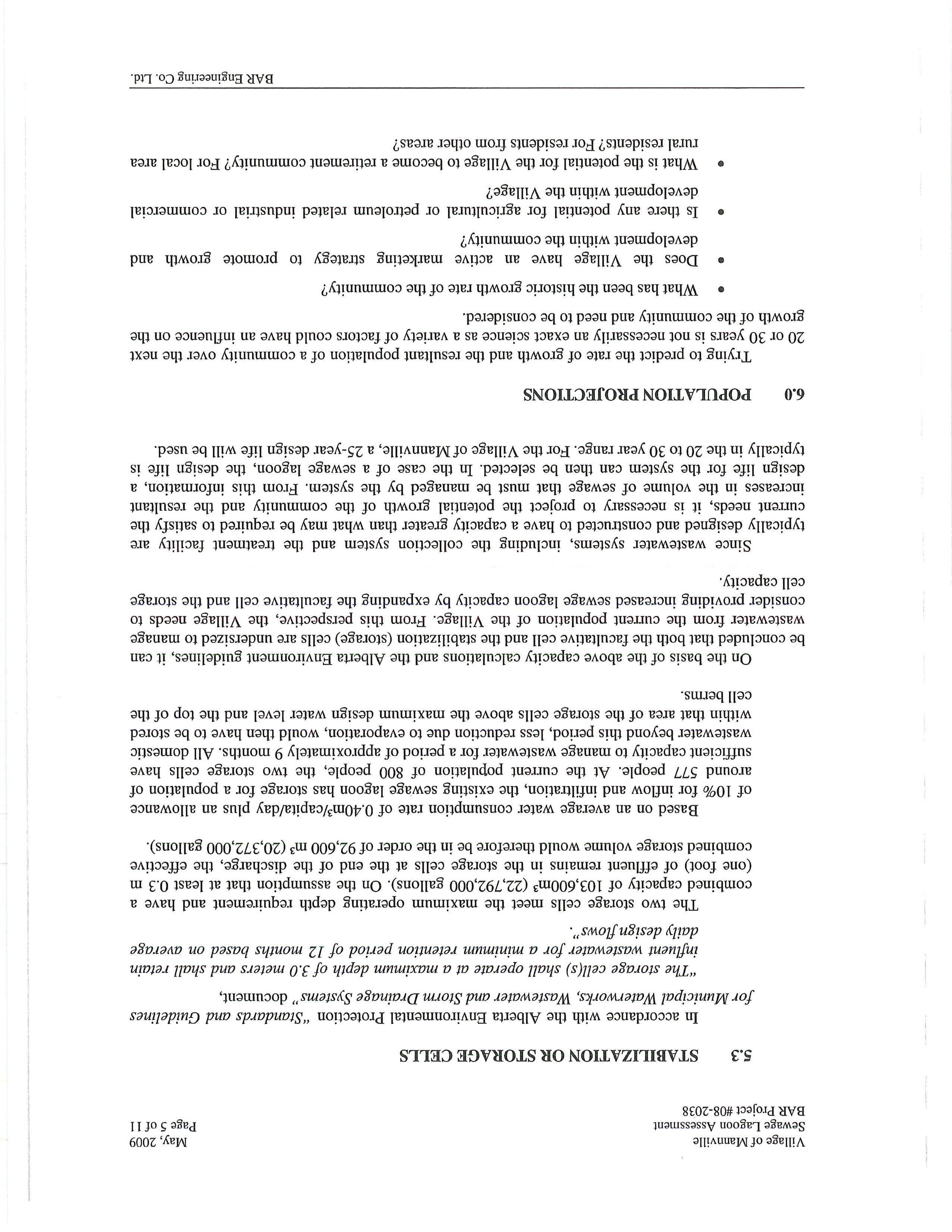
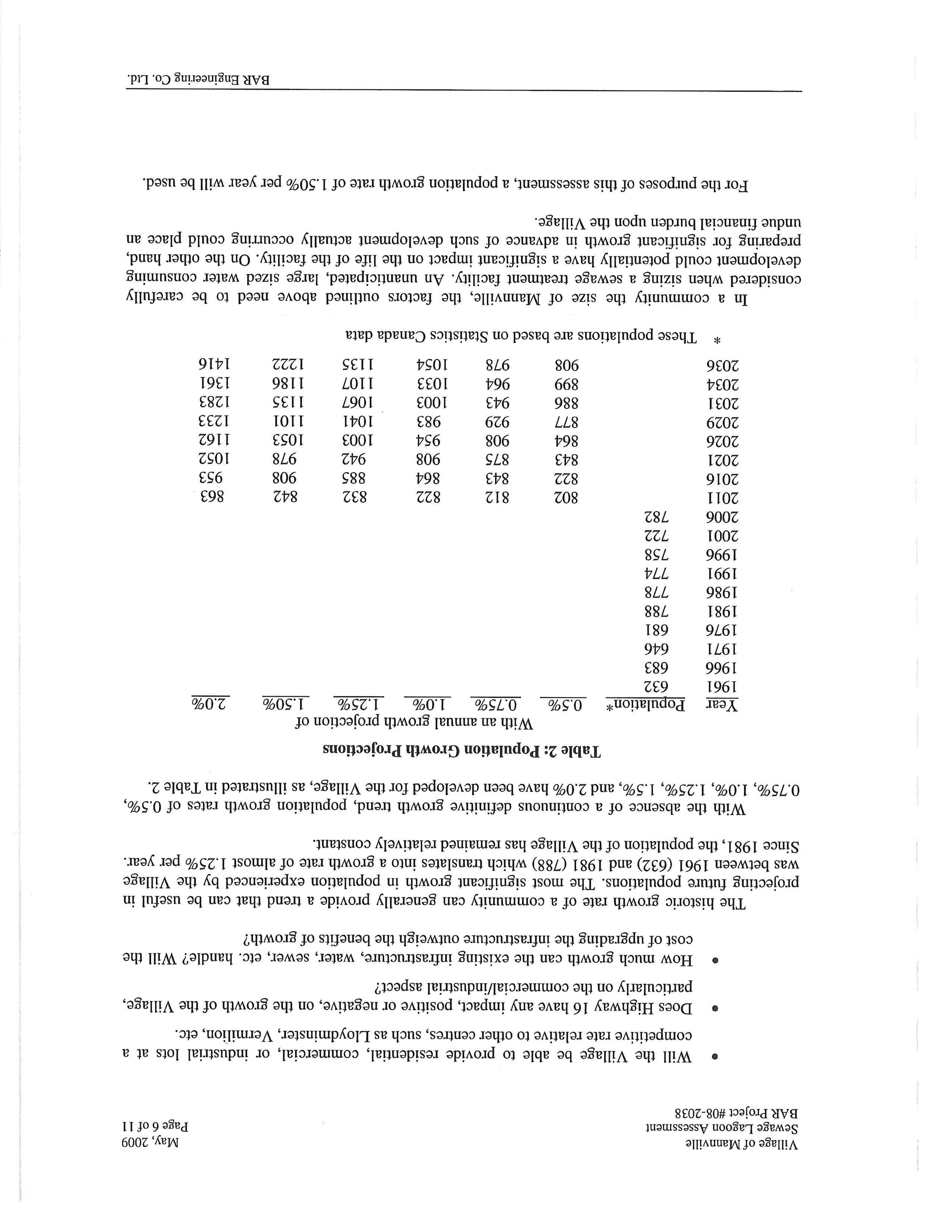
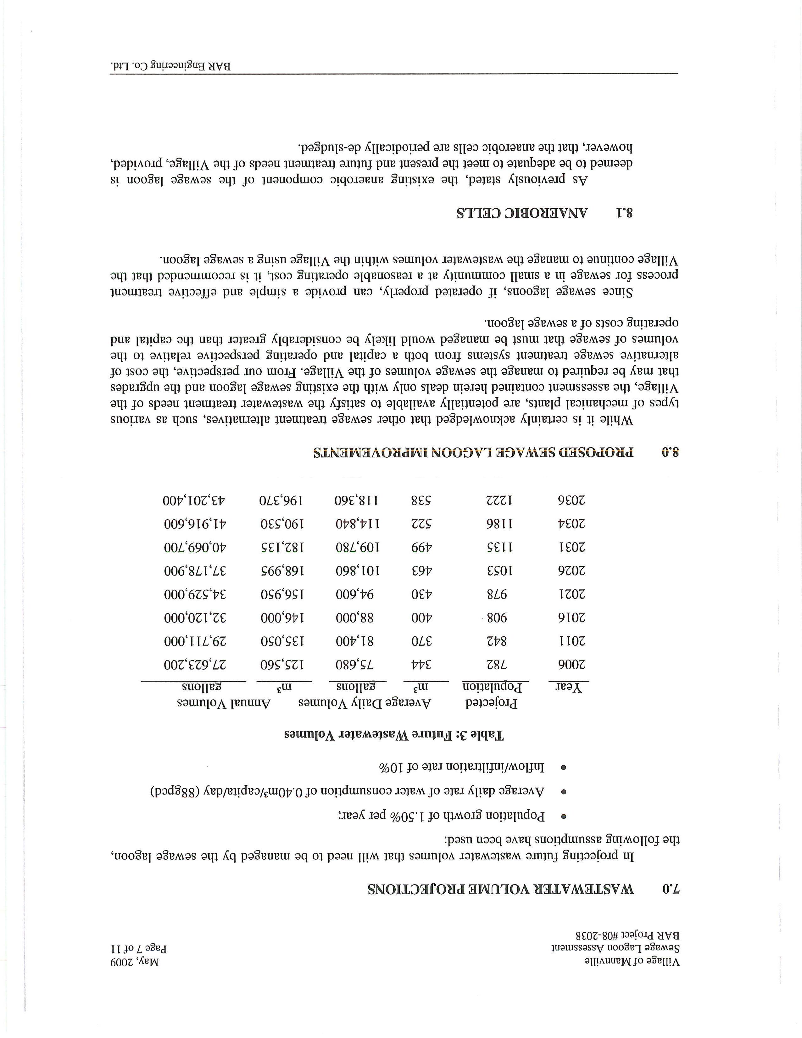
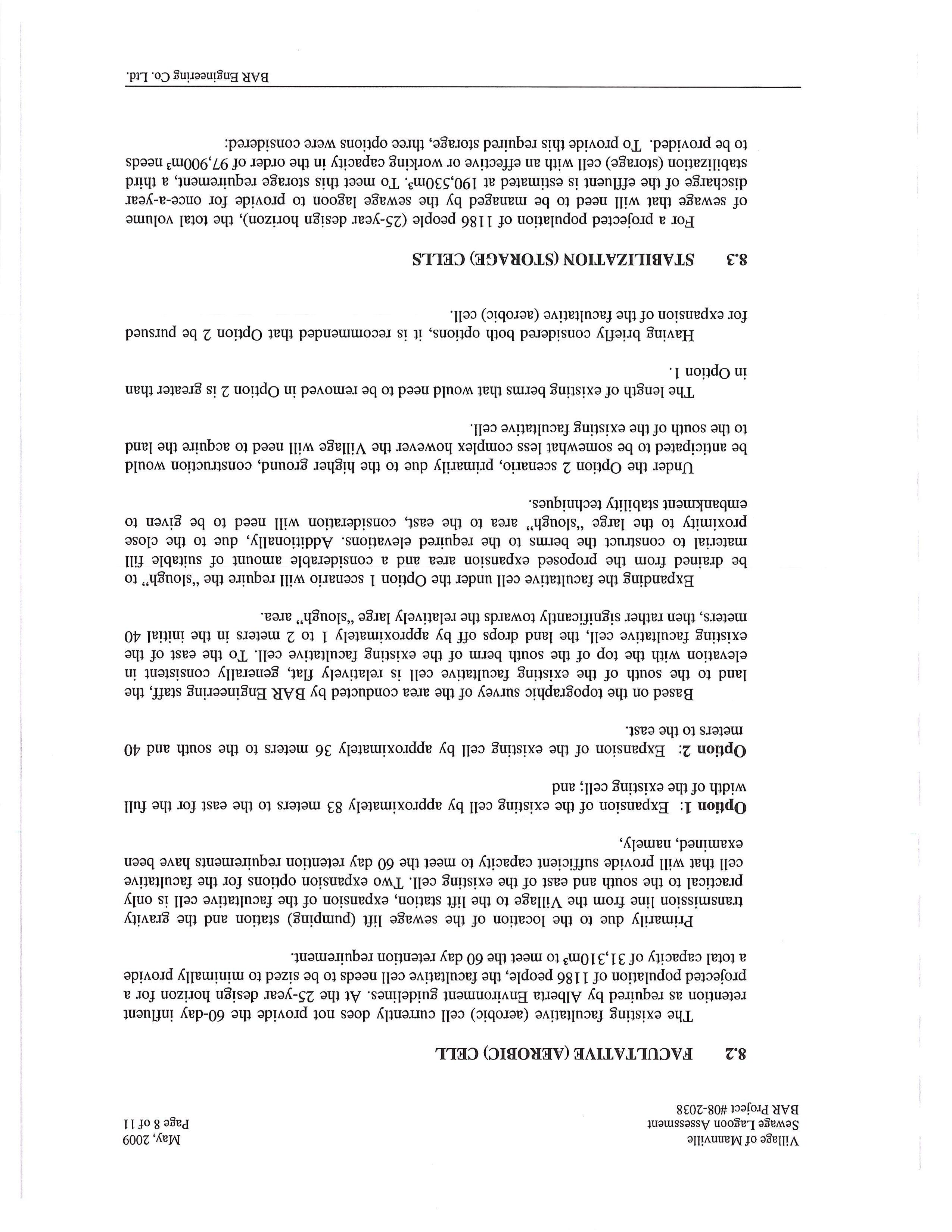
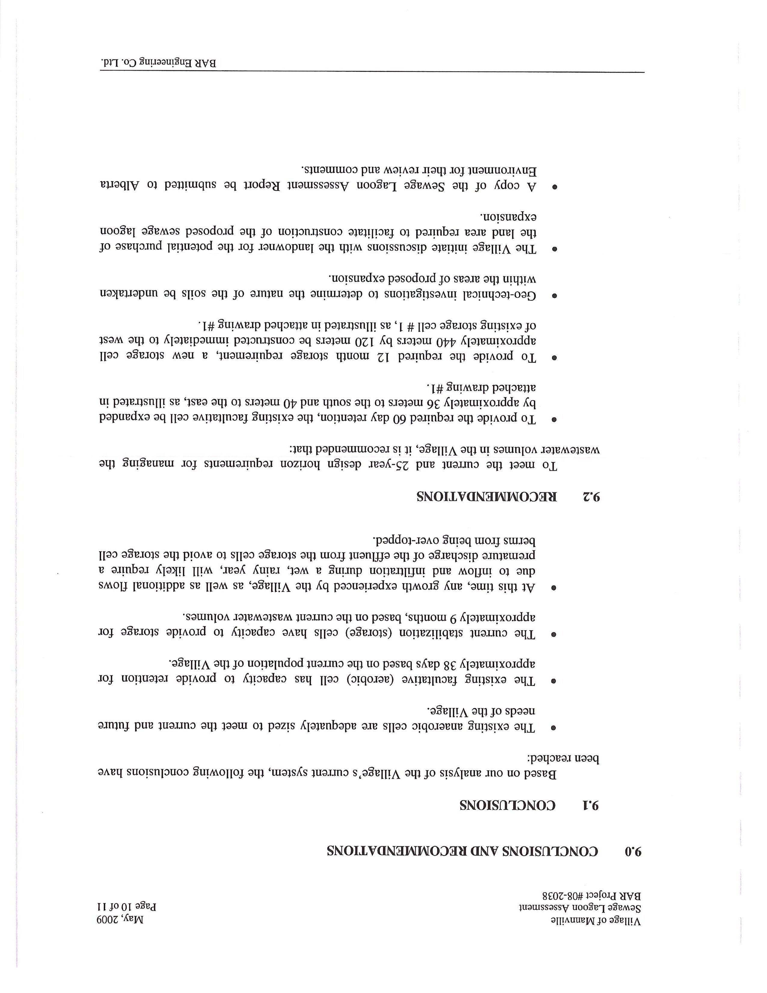
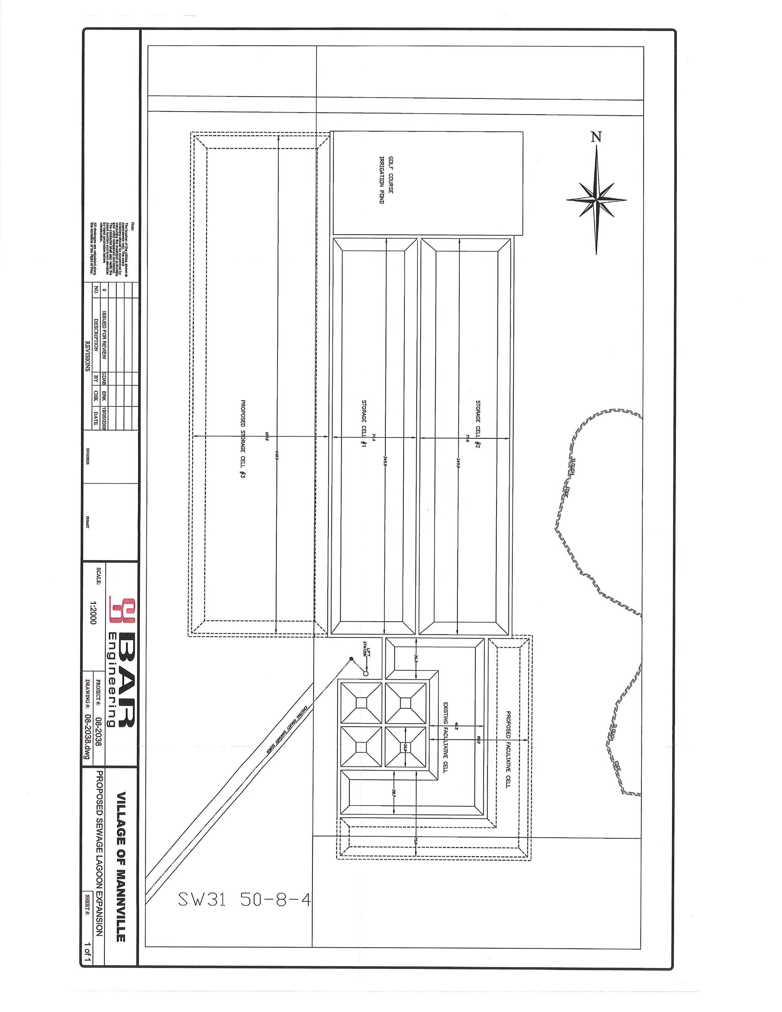
D Appendix D Transportation Review
Does not form part of this Bylaw.
Prepared by: BAR Engineering

August 11, 2022
03-22-0039
Vicki Dodge
Red Willow Planning
Unit 10, 44 St. Thomas Street
St. Albert, AB T8N 6N8
Dear Ms. Dodge:
Re: Minburn Industrial ASP
Transportation Review – Final v2.0
1. INTRODUCTION
Red Willow Planning is working with the County of Minburn and the Village of Mannville on the development of an industrial Area Structure Plan (ASP) north of Highway 16 and east of the Village of Mannville, AB. As part of the planning process, the need for a transportation review has been identified. The review is anticipated to provide an overview of the transportation opportunities and constraints in and adjacent to the study area.
2. EXISTING CONDITIONS
2.1
Study Area
The study area is generally bounded by Highway 16 to the south, Twp Rd 504 to the north, the quarter section line east of Rge Rd 85to the east, and the Village of Mannville to the west.
2.2 Roadways
The study area is currently served by the following roadways:
Highway 16 is classified as a rural freeway divided (RFD) roadway and is currently developed as a paved four-lane rural divided highway with a posted speed limit of 110 km/hr. The section of Highway 16 adjacent to the study area currently includes at-grade unsignalized intersections at Highway 881, Range Road 85, and Range Road 84.
Highway 881 is classified as a rural collector undivided (RCU) and is currently developed as a paved two-lane rural undivided highway with a posted speed limit of 50 km/hr through Mannville and a posted speed limit of 100 km/hr external to Mannville. Existing intersections at 48 Avenue (Twp Rd 503B) and 50 Avenue (Twp Rd 504) are currently unsignalized. A sidewalk is provided on the west side of Highway 881 between 48 Avenue and 50 Avenue.
Twp Rd 503B is currently developed as a 2-lane paved rural collector roadway with a posted speed limit of 80 km/hr.
Twp Rd 504 is currently developed as a 2-lane rural collector roadway with an oiled surface. The posted speed limit along Twp Rd 504 is 80 km/hr.
Rge Rd 85 is currently developed as a 2-lane gravel collector roadway with a posted speed limit of 80 km/hr.
Rge Rd 84 is currently developed as a 2-lane gravel collector roadway with a posted speed limit of 80 km/hr.
2.3 Traffic
Table 1 summarizes the existing Average Annual Daily Traffic (AADT) volume estimates from Alberta Transportation’s traffic data mapping website. The table includes data from 2016, 2019, and 2021 to reflect a variety of conditions before and during the pandemic.
Table 1: AADT Volume Estimates
Highway 16 east of Highway 881
Highway 881 North of Highway 16
Highway 881 North of 48 Avenue
48 Avenue (Twp Rd 503B) east of Highway 881
*Count Year
2.4 Railway
There is an existing Canadian National Railway (CNR) main line that runs northwest to southeast through the plan area. At-grade railway crossings are provided at Highway 881, Rge Rd 85, and Rge Rd 84. The Highway 881 rail crossing currently includes flashing lights and bells, while the crossings at Rge Rd 85 and Rge Rd 84 include passive railway crossing signs.
Minburn Industrial ASP |
Review – Final v2.0 2 bunt & associates |
No.
Transportation
Project
03-22-0039 | August 11, 2022
LOCATION 2016 2019 2021
6,810 vpd* 6,930 vpd 5,320 vpd*
1,420 vpd* 1,390 vpd 1,400 vpd*
2,120 vpd 1,940 vpd* 1,820 vpd
430 vpd 360 vpd* 340 vpd
3. FUTURE CONDITIONS
3.1
Roadways
As noted, Highway 16 is classified as a rural freeway divided (RFD) highway within Alberta Transportation’s roadway hierarchy. The roadway is currently developed as an arterial facility with numerous at-grade intersections; therefore, the conversion of the roadway to a freeway standard requires the identification of future interchange locations, the closure of at-grade intersections, and the development of alternate access strategies.
CH2M Hill prepared the Highway 16 Access Management Plan: Highway 36 to Range Road 2-3 in 2010 on behalf of Alberta Transportation. In the vicinity of the study area, the management plan identifies the conversion of the Highway 16/Highway 881 intersection to an interchange and the closure of all the atgrade intersections between Highway 881 and Highway 41, including the Highway 16/Rge Rd 85 and Highway 16/Rge Rd 84 intersections. Land access to the properties north of Highway 16 and east of Highway 881 will be provided via Twp Rd 504 and existing service roads. The study generally identified a rural local undivided cross-section as the minimum cross-section for the alternate access roadways.
The Highway 16 access management plan adjacent to the study area is illustrated in Figure 1. The study area has been highlighted in yellow. A copy of the plan from the original report is attached for reference.
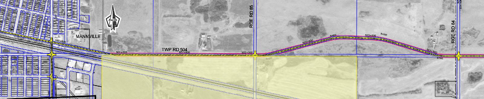
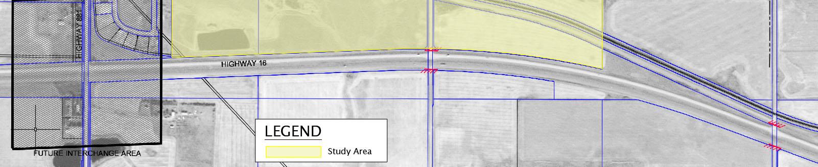
Minburn Industrial ASP | Transportation Review – Final v2.0 3 bunt & associates | Project No. 03-22-0039 | August 11, 2022
Figure 1: Highway 16 Access Management Plan for Study Area
Source: CH2M Hill Highway 16 Access Management Study
4. PROPOSED DEVELOPMENT
The proposed ASP would establish the framework for industrial development in the study area. Based on a preliminary review, it is estimated that the study area includes approximately 311 acres of gross area. Based on a preliminary lot layout provided by Red Willow Planning, a range of lot sizes are proposed that could be attractive to a number of different types of industrial businesses.
The lands immediately adjacent to the Village of Mannville are anticipated to be integrated with existing industrial land uses in terms of potential future servicing, including the potential use of existing roads and access within the Village. The remaining study area is anticipated to require new access to existing township and range roads.
Trip generation varies by the type and intensity of development; however, based on a rural industrial daily trip generation rate of 20 trips/acre measured in Acheson, Parkland County, full development of the study area could generate in the order of 6,000 vpd to 6,500 vpd. Although the Acheson industrial area covers significantly more land than included in the Minburn Industrial ASP area, the proposed lot sizes and potential typology of industrial businesses that could be attracted to the study area are anticipated to be similar to the size and types of businesses currently developed in Acheson; therefore, the application of the measured Acheson trip rate is anticipate to provide an appropriate estimate for potential traffic generation at the ASP level of planning. This preliminary estimate is intended to help guide discussions regarding access and circulation and may be conservative depending on the ultimate mix and intensity of industrial uses constructed in the study area.
5. TRANSPORTATION EVALUATION
5.1
Land Access
The future upgrading of Highway 16 to a freeway will result in significant impacts to land access in the study area. While timing for the future freeway upgrade is not currently known, the roadway network servicing the plan area should be developed based on the ultimate freeway conversion plan to minimize future disruptions. The following outlines the key land access components to be considered during the development of the ASP land use concept.
Minburn Industrial ASP | Transportation Review – Final v2.0 4 bunt & associates | Project No. 03-22-0039 | August 11, 2022
5.1.1
Roadway Hierarchy
The County roadways within and adjacent to the study area are currently classified as collector roadways. As per the Transportation Association of Canada’s (TAC) Geometric Design Guide for Canadian Roads, traffic movement and land access are of equal importance for roadways classified as rural collectors. The following typical characteristics are also noted:
Daily traffic volumes <5,000 vpd
Interrupted flow
Design Speed 60 km/hr to 110 km/hr
Up to 30% trucks in the 3t to 5t range
Connect to locals, collectors, and arterials
Based on TAC, the typical minimum spacing between intersections along collector roadways is 60m; although, some counties identify intersection spacing of 100m for rural industrial major collectors.
Intersection spacing impacts overall roadway operations, level of service, and vehicle capacity. With the implementation of the Highway 16 freeway conversion program, Twp Rd 504 is anticipated to provide a cross-county function, while Twp Rd 503B is anticipated to balance traffic movement and land access within the study area. Therefore, these east-west collectors are recommended to include a minimum intersection spacing of 100m. Given the location of the CNR and the depth of the development area on either side of the CNR, minimum intersection spacing along Rge Rd 85 is recommended to be 60m.
5.1.2 Railroad Crossings
An at-grade railroad crossing is currently provided at Rge Rd 85 approximately 300m north of Highway 16 and an at-grade railroad crossing is currently provided at Rge Rd 84 approximately 65m north of Highway 16.
Based on a review of the Government of Canada’s Grade Crossing Standards, a minimum spacing of 30m is required between the edge of the travelled way and the nearest rail of the grade crossing.
To be conservative, it is recommended that the first intersection north and south of the railroad on Rge Rd 85 be located a minimum of 60m from the rail crossing (nearest rail to edge of the travelled way). The provision of 60m spacing from the railroad at the planning stage provides additional flexibility in the future intersection design to ensure that the ultimate configurations provide sufficient minimum stacking distance for a semi-trailer (WB-21) or a double trailer combination (WB-23) between any future crossing protection north/south of the railroad and adjacent intersections. This is anticipated to require the realignment of Twp Rd 503B south of its current location.
Minburn Industrial ASP | Transportation Review – Final v2.0 5 bunt & associates | Project No. 03-22-0039 | August 11, 2022
The existing Twp Rd 503B/Rge Rd 84 intersection is located approximately 27m south of the railway and may not meet the current standard. As well, the existing spacing to Highway 16 may not be sufficient to accommodate modifications to the intersection location prior to closure of the Highway 16/Rge Rd 84 intersection. While spacing may not be ideal, it is recommended that the Twp Rd 503B/Rge Rd 84 intersection be maintained in the plan to provide secondary emergency access to developable lands located south of the CNR between Rge Rd 85 and Rge Rd 84. A more detailed review of Rge Rd 84 between Highway 16 and the CNR should be completed prior to development east of Rge Rd 85 to determine if the intersection can be shifted south to meet minimum spacing standards.
The existing railroad crossing controls in and adjacent to the study area may need to be upgraded as traffic volumes increase on the roadway network.
5.1.3
Roadway Alignment
Roadway alignment can impact sightlines at intersections. Rge Rd 85 and Rge Rd 84 are generally straight and do not include horizontal curves that could impact sightlines. Twp Rd 503B includes a curve east of Rge Rd 85; however, the radius appears to be generous enough such that sightlines may not be a significant concern.
Along Twp Rd 504, the roadway curves north to avoid a wetland area between Rge Rd 85 and Rge Rd 84. Although access may not be provided through the wetland area, if it is considered in the future, sightlines at potential intersection locations should be reviewed.
Consider sightlines at intersections east and west of Rge Rd 85 if Twp Rd 503B is realigned south to accommodate additional spacing from the CNR.
5.1.4
Highway 16 and Highway 881 Interchange
Details regarding the type of interchange that will ultimately be constructed at Highway 16 and Highway 881 were not provided as part of the access management study; however, the potential interchange footprint identifies land impacts to the existing industrial area in south Mannville. It was noted that the land adjacent to Mannville may be serviced through the existing industrial area in the village; however, the potential interchange construction should be considered when developing the access strategy for this area.
Minburn Industrial ASP | Transportation Review – Final v2.0 6 bunt & associates | Project No. 03-22-0039 | August 11, 2022
5.1.5
Recommended Access
Figure 2 illustrates the recommended minimum intersection spacing along the key study roadways. The posted speed limits along the collector roadways should be reviewed in the context of future development and ultimate access spacing.
Figure 2: Recommended Intersection Spacing
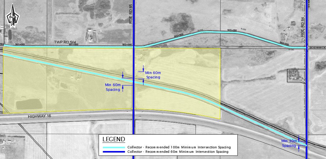
5.2
Truck Circulation
Highway 16 is an existing high load corridor adjacent to the study area, accommodating a maximum height of 12.8m and is anticipated to continue to be a high load connector route in the future. As well, Highway 16 can accommodate long combination vehicles up to 38m long.
As an industrial area, all roadways within the plan area should be designed to accommodate trucks; however, if end users that may require high load or long combination vehicles are considered within the plan area, additional design considerations will be required when establishing the roadway network.
5.3 Staging
Timing for the implementation of the Highway 16 access management plan is currently unknown; therefore, it is anticipated that development may pr oceed within the study area based on the existing roadway network. It is recommended that the internal roadway network be developed based on the ultimate plan. Specifically, access locations to Rge Rd 85 between Highway 16 and the CNR should be established early in the land development process to minimize disruptions in the future. It is also recommended that the future Highway 16 intersection closures be clearly communicated to future end users.
Minburn Industrial ASP | Transportation Review – Final v2.0 7 bunt & associates | Project No. 03-22-0039 | August 11, 2022
Traffic impact assessments (TIAs) will be required by Alberta Transportation for development within the study area. Intersection improvements may be required at intersections along Highway 16 under the existing at-grade configurations depending on projected site generated traffic volumes and design vehicle requirements.
6. CONCLUSIONS
It is anticipated that the above provides sufficient information to assist in the development of an internal roadway network as part of the overall planning process. Please contact the undersigned with any questions regarding our submission.
Yours truly,
Bunt & Associates
Catherine Oberg Principal
This electronic document includes a certified digital signature and represents the original document retained on file. Any printed versions of this report are considered copies and can be confirmed by referring to the original electronic document.
This document entitled “Minburn Industrial ASP Transportation Review” was prepared by Bunt & Associates for the benefit of the County of Minburn and the Village of Mannville to provide transportation information for consideration in the planning of the Minburn Industrial ASP. The analysis and conclusions/recommendations in the report reflect Bunt & Associates’ best professional judgment based on the knowledge and information available to Bunt & Associates at the time of preparation.
The County of Minburn and the Village of Mannville, including employees, members of Council, and Regulatory Board members shall be entitled to rely on this report for the specific purpose for which it was prepared. The County of Minburn and the Village of Mannville may also provide copies of the report to external governmental bodies having jurisdiction related to the project for which it was prepared.
Any use made of this report by a third party beyond those specifically noted here, or any reliance on or decisions based on it by any such third party, are the responsibility of such third parties. Bunt & Associates accepts no responsibility for damages, if any, suffered by such third parties as a result of decisions made or actions based on this report.
8
Minburn Industrial ASP | Transportation Review – Final v2.0
bunt & associates | Project No. 03-22-0039 | August 11, 2022
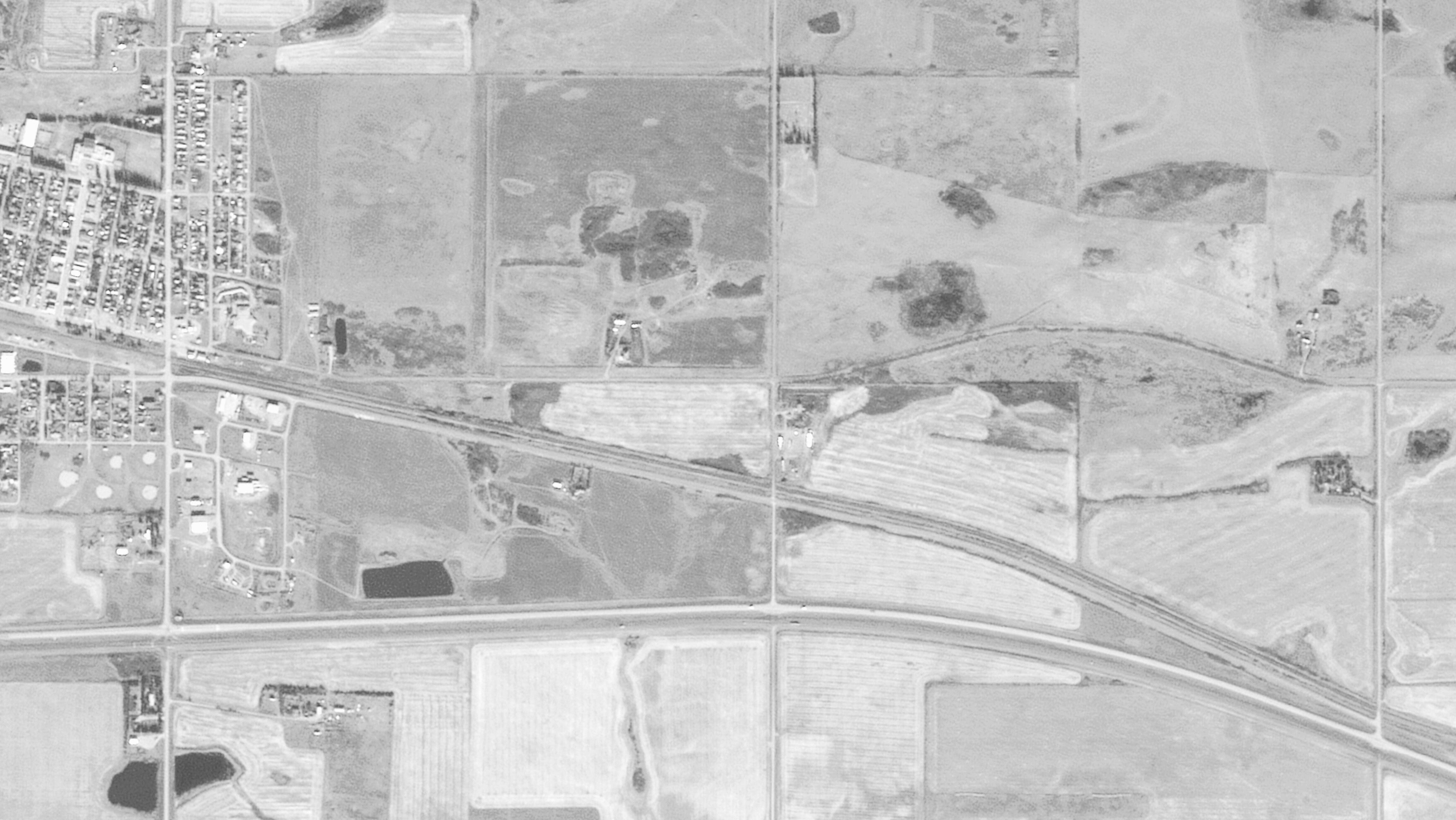

E Appendix E Servicing Brief
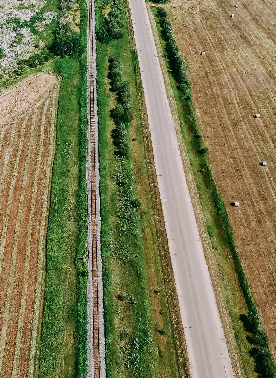
Does not form part of this Bylaw.
Prepared by: BAR Engineering

January 19, 2023 | Project No.: 22MU-495300
Red Willow Planning 10617 – 98 Avenue
Morinville, AB
T8R 1E4
Attention: Vicki K. Dodge, RPP
Re: East Industrial Park Area Structure Plan – Servicing Brief County of Minburn No. 27, AB
1.0 Introduction
Red Willow Planning, on behalf of the County of Minburn No. 27 (County), engaged BAR Engineering Co. Ltd. (BAR) to prepare a servicing brief associated with, and to complement, the preparation of the East Industrial Park Area Structure Plan (ASP) associated with the future development of the NW and NE ¼ Section 19-50-8-W4M and the NW ¼ Section 20-50-8-W4M. Servicing options and recommendations for the East Industrial Park water, wastewater, stormwater management, franchise utilities, and transportation network are provided in this servicing brief.
2.0 Background
The East Industrial Park is located directly east of the Village of Mannville (Mannville, or the Village), which encompasses the east half of the NW ¼ Section 19-50-8-W4M, the NE ¼ Section 19-50-8-W4M, and the NE ¼ Section 20-50-8-W4M. The subject ASP parcel is bounded by the Trans Canada Highway 16 to the south, the Village boundary to the west, Township Road 504 to the north and the east quarter section line of the NW ¼ Section 20-50-8-W4M Canadian National Railway and Mannville Road (formerly Highway 2) bisect the parcel from the northwest corner to the southeast. Location of the subject ASP parcel is shown in Figure 2-1
According to the County’s Land Use Bylaw 1254-16, the existing ASP parcel districts are as follows:
• NW ¼ Section 19-50-8-W4M is zoned Direct Control,
• A small parcel in the southeast corner of the NE ¼ Section 19-50-8-W4M is zoned Rural Commercial District, and
• Remnant of the ASP area is zoned Agricultural.
Figure 2-2 illustrates the existing land use.
An Intermunicipal Development Plan (IDP) was adopted by the County and Village in 2015, which includes the ASP area. The IDP’s purpose, as defined in the document, is to support ongoing cooperation between the two municipalities and to support the successful continuation of the Village as an incorporated municipality. Future land use for all areas of the subject ASP area is identified as Industrial/Commercial in the IDP.
The County of Minburn is proceeding with the ASP for the subject area resulting from the availability of funding and the IDP identifying the requirement for a joint ASP, and with the intent of the ASP area to be
Red Willow Planning
BAR Project No.: 22MU-495300
January 19, 2023
zoned, subdivided, and developed for the Rural Industrial land use. Large lot sizes are typical for rural industrial developments, which is consistent with the proposed lotting plan provided by Red Willow Planning. Proposed lot sizes range in size from roughly 1.00 acres to 9.97 acres as shown in Figure 2-3 It is important to note that the proposed lotting provided by Red Willow Planning is conceptual and will be refined during future development stages.
3.0 Servicing
3.1. Water
County of Minburn does not currently have an existing municipal water distribution system within the vicinity of the ASP lands to provide potable water to the development. As such, either private on-site potable water systems, such as wells or cisterns, will need to be utilized for the development or a connection to the Alberta Central East (ACE) Regional Water System will be required.
Two options for water servicing will be considered for the ASP:
• Rural Water Servicing Option, and
• Hybrid Water Servicing Option consisting of Municipal Water Services for the NW ¼ Section 1950-8-W4M and Rural Wastewater Servicing for the remainder of the lands.
Rural water servicing consists of individual water wells. If water wells are utilized for the development, groundwater evaluations and/or hydrogeological assessments will be required prior to and as part of the subdivision process to obtain the required approvals and authorization from Alberta Environment and Parks and Sustainable Resource Development to divert and use groundwater.
Hybrid water servicing option consists of extending the existing water distribution from the Village of Mannville into the NW ¼ Section 19-50-8-W4M from the west. The Village is supplied with water from the ACE Waterline Corporation. The ACE Waterline Corporation is a regional entity that supplies high quality potable water to the municipalities in the County of Minburn, Two Hills and Vermilion River.
A watermain, owned and operated by the County, would be required from the connection points at 47A Avenue/45 Street and 45 Street and looped throughout the development to provide service to the Rural Industrial lots. It is important to note that ACE does not provide distribution pressures, so either the water supply would be through a trickle feed system to fill private on-site cisterns, or the County could construct a reservoir and pump station to provide adequate distribution pressures to the ASP lands. Figure 3-1 illustrates the location of the existing ACE Transmission Line and the possible connection point and watermain alignment to the north side of the ASP lands. Application to connect the ACE Transmission Line would be undertaken at future design stages of the development prior to subdivision.
3.2. Wastewater
Two options for wastewater servicing will be considered for the ASP:
• Rural Wastewater Servicing Option, and
• Hybrid Wastewater Servicing Option consisting of Municipal Wastewater Services for the NW ¼ Section 19-50-8-W4M and Rural Wastewater Servicing for the remainder of the lands.
Rural wastewater servicing consists of private on-site sewage disposal, which could include holding tanks with truck pump out or septic tanks discharging to treatment fields or mounds. Unlike municipal wastewater collection systems, on-site sewage systems include either collection of the wastewater and hauling offsite or collecting and treating the wastewater onsite prior to discharging to the environment. Implementation of private sewage systems shall be in accordance with the Alberta Private Sewage Systems current Standard of Practice at the subdivision stage.
BAR ENGINEERING | 2
Red Willow Planning
BAR Project No.: 22MU-495300
January 19, 2023
Hybrid wastewater servicing option consists of extending the sanitary sewage collection system from the Village of Mannville into the NW ¼ Section 19-50-8-W4M from the west. Sewage for the Village is treated at the Village Lagoon located approximately a half mile northeast of the Village boundary with treated effluent being discharged into the Vermilion River. In 2009, BAR completed an assessment of the Village’s Lagoon which determined that the existing lagoon had a facultative (aerobic) cell capacity for 515 people and storage cell capacity for 577 people. The IDP identified that the Village’s population in 2011 was 803, meaning that the lagoon is undersized for the current population based on BAR’s 2009 report and assuming that the Village has not undertaken any capacity improvements to their existing lagoon. A municipal wastewater collection system for the ASP lands could consist of a low-pressure sewage collection system, and/or gravity sanitary sewer mains in combination with lift stations. Figure 3-2 illustrates the location of the existing sanitary sewer system and lagoons within the Village of Mannville and the possible connection point and sanitary sewer alignment to the west side of the ASP lands.
Sanitary sewer design flows were calculated utilizing the City of Lloydminster Municipal Development Standards, October 2020 edition The following parameters were used to determine the sanitary sewer flow rate:
• Equivalent Population = 48 persons/ha
• Minimum Average Contribution = 320 L/person/day
• C Peak Factor = 1+14 (4+P1/2) Where P is the population in thousands
• Infiltration Rate = 0.28L/s/ha
• Manning’s “n” value = 0.013
Based on the above parameters, the estimated total design peak flow rate for the site would be 10.3L/s.
The proposed sanitary sewer main was sized using the Manning’s equation:
Q = AR0.667S0.5 n
Where: Q = Design flow in m3/s
A = Cross sectional area in m2
R = Hydraulic radius (area/wetted perimeter) in m
S = Slope of hydraulic grade line (m/m)
n = Roughness coefficient
According to the City of Lloydminster Municipal Development Standards, October 2020 edition, the minimum required sanitary sewer pipe size for a commercial/residential area is 250mm diameter at a minimum 0.28% grade. The velocity within the pipe must be between 0.6m/s to 3.0m/s. According to BAR’s calculations, a 250mm sanitary sewer pipe at 0.28% grade will provide sufficient capacity for the development and the velocity within the pipe within the tolerable range.
3.3. Stormwater Management
The ASP lands is split into two drainage basins with the drainage divide approximately located along Range Road 85. The NW and NE 19-50-8-W4 generally drain from the north to the south and ultimately discharge via a culvert crossing under Highway 16. Land within NW 20-50-8-W4 slopes away from Highway 16 north towards Township Road 504.
For flexibility of development, two stormwater management scenarios have been analyzed for the ASP as follows:
BAR ENGINEERING | 3
Red Willow Planning
BAR Project No.: 22MU-495300
January 19, 2023
• SWM Scenario 1 – County stormwater management system for the entire developed area consisting of two stormwater management facilities to collect runoff and discharge at a controlled release rate to a downstream drainage path.
• SWM Scenario 2 – County stormwater management system for the lots proposed within the NW19-50-8-W4 and provision for private on-site stormwater management for the remaining proposed lots.
In both scenarios, a series of drainage ditches, including roadside ditches, and stormwater management facilities (SWMF) will be utilized to convey and control stormwater runoff from the proposed development. The following sections provide an overview of the proposed stormwater management measures for each scenario with further detail provided in the attached Stormwater Management Plan.
3.3.1.SWM Scenario 1
The Canadian National Railway (CN Rail), bisecting the subject lands, will divide the proposed drainage into a north and south catchment. Surface runoff within the north parcel of the NE 19-50-8-W4 will be collected and conveyed via roadside ditches to a proposed dry stormwater management facility located in the northwest corner of the quarter section. The parcel of lands south of the CN Rail will also drain via roadside ditches to a proposed wet stormwater management facility located along the west side of the NE 19-50-8-W4 extending into the southeast corner of the NW 19-50-8-W4. Overland flow is designed to run off from the industrial lots to the roadside ditches with minimum 2% lot grades and minimum roadside ditch grades of 0.2%. Two stormwater management facility locations have been identified as shown in Figure 3-3, however, phasing of the development could result in additional interconnected stormwater management facilities in locations best suited to the phasing and development.
3.3.2.SWM Scenario 2
SWM Scenario 2 consists of similar overall drainage conveyance and patterns as Scenario 1 with runoff flowing overland from lots with a minimum 2% grade to roadside ditches at minimum grade of 0.2% A dedicated wet stormwater management facility is proposed to collect runoff from the smaller lots along the west boundary of the ASP lands within the NW19-50-8-W4 Stormwater management for the remaining larger proposed Rural Industrial lots includes provision for on-site private stormwater storage. Stormwater from the NW and NE 19-50-8-W4 will be conveyed to the natural drainage run within the SE19-50-8-W4, south of Highway 16 Private on-site stormwater systems from the proposed lots in the NW20-50-8-W4 will discharge north across Township Road 503B and the CN Rail to the natural discharge point in the northeast corner of the quarter section. Figure 3-4 illustrates the stormwater management measures for Scenario 2.
3.4. Franchise Utilities
Power, natural gas, and communication services are all located within the vicinity of the ASP lands and will be extended from the nearest connection location for the planned subdivision. Application to the utility provider for connection and/or extension of service to the proposed development will be required at the subdivision stage.
3.5.
Transportation Network
Access to the ASP area is currently provided via 46 Street, 47A Avenue, Township Road 504, Township Road 503B, and Range Road 85. 46 Street and 47A Avenue provides access from the Village on the west side of the development. Range Road 85 connects Highway 16 to the south, Township Road 503B and Township Road 504 to the north. Existing roadways are shown in Figure 2-1. The road allowance widths are as follows:
• 46 Street and 47A Avenue are 25m
• Township Road 504 is 20m
BAR ENGINEERING | 4
Red Willow Planning
BAR Project No.: 22MU-495300
January 19, 2023
• Township Road 503B is 40m
• Range Road 85 from Highway 16 to Township Road 503B is 30m
• Range Road 85 from Township Road 503B to Township Road 504 is 20m
Transportation networks typically consist of three classifications of roadways: arterial, collector, and local. Roadway classification is determined based on connectivity of the transportation network and traffic volumes. In general, arterial roadways have higher traffic volumes and connect to collector roadways, while collector roadways connect to local roads with the least traffic volume. Direct access to private development is permitted on local and collector road classifications, but not arterial. The proposed transportation network, including roadway classifications, is shown in Figure 3-5
All proposed roadways within the ASP development will be rural cross section roads with roadside ditches to provide drainage and convey stormwater runoff as noted in Section 3.3 and will be developed to the current County of Minburn Road Standards at time of development. The following recommendations are provided for the ASP transportation network at future development stages:
• Undertake a traffic impact assessment prior to subdivision to determine if intersection upgrades or controls are required as a result of development.
• Complete a geotechnical investigation to confirm soil stratigraphy, suitability of existing soil for construction, and recommended road pavement structures based on soils and vehicular loading.
• Construct roadways to accommodate a minimum 9m finished top width for truck traffic.
• Widen Township Road 504 road allowance to 30m for construction of the proposed rural road cross section.
4.0 Closure
If you have any questions or require any clarifications regarding this servicing brief, please do not hesitate to contact me at (780) 875-1683 or via email at caitlin.atkins@bareng.ca.
Yours truly, BAR Engineering Co. Ltd.
 Caitlin Atkins, P. Eng. Intermediate Engineer Municipal Division
Reviewed By,
Scott Simons, P. Eng. Manager Municipal Division
Attachments: East Industrial Park Stormwater Management Plan Report, January 18, 2023
BAR ENGINEERING | 5

CANADIANNATIONALRAILWAY
ASPBOUNDARY NE1950-8-4
3999R
NE1950-8-4
SE1950-8-4
SE2050-8-4 SW1950-8-4 VILLAGEOFMANNVILLE RANGE RD 85 HWY 881 NW1950-8-4 TWPRD504 TWPRD503B HIGHWAY16 47AAVENUE 46 STREET 45 STREET Drawing#: Scale: Drawnby: Date: Approvedby: Revision: 01/19/2023 CMA DJB Figure2-1 1:7500 0 FIGURE2-1:LOCATIONPLAN SERVICINGBRIEF CountyofMinburnNo.27,Alberta Drawing path: P:\Municipal\22MU-495300 RWP County of Minburn ASP\400-Drawings\Figures\22MU-495300Figure 2-1 Location Plan.dwg Layout: Figure 111x17 Figure Last Saved: Jan 19, 202311:57 AM Plotted: January 19, 2023 12:01:51 PM N
1061JY
SE30-50-8-4 SW29-50-8-4 SE29-50-8-4 NW1950-8-4 NW2050-8-4 SW2050-8-4
NE2050-8-4
CANADIANNATIONALRAILWAY
NE1950-8-4
3999R 1061JY NE1950-8-4
SE1950-8-4
SW1950-8-4 VILLAGEOFMANNVILLE RANGE RD 85 HWY 881 NW1950-8-4 TWPRD504 TWPRD503B HIGHWAY16 ASPBOUNDARY Drawing#: Scale: Drawnby: Date: Approvedby: Revision: 01/19/2023 CMA DJB Figure2-2 1:7500 0 FIGURE2-2:EXISTINGLANDUSE SERVICINGBRIEF CountyofMinburnNo.27,Alberta Drawing path: P:\Municipal\22MU-495300 RWP County of Minburn ASP\400-Drawings\Figures\22MU-495300Figure 2-2 Existing Land Use.dwg Layout: Figure 111x17 Figure Last Saved: Jan 19, 202311:57 AM Plotted: January 19, 2023 12:01:58 PM N DIRECTCONTROL AGRICULTURAL RURALCOMMERCIALDISTRICT
SE30-50-8-4 SW29-50-8-4 SE29-50-8-4 NW1950-8-4 NW2050-8-4 SW2050-8-4
NE2050-8-4 SE2050-8-4
SW1950-8-4 VILLAGEOFMANNVILLE
CANADIANNATIONALRAILWAY
NW2050-8-4
TWPRD503B
ASPBOUNDARY
NE2050-8-4
HIGHWAY16
SW2050-8-4
SE1950-8-4
SE2050-8-4
0.97ha 2.40ac 0.68ha 1.68ac 0.41ha 1.00ac 0.41ha 1.00ac 0.58ha 1.44ac 0.42ha 1.05ac0.41ha1.01ac0.41ha1.01ac0.41ha 1.01ac 0.81ha 2.00ac 1.29ha 3.18ac 1.21ha 3.00ac 1.21ha 3.00ac 0.41ha 1.00ac 0.41ha 1.00ac 0.43ha 1.06ac 2.83ha 6.99ac 2.83ha 6.99ac 2.83ha 6.99ac 2.84ha 7.01ac 3.76ha 9.29ac 3.25ha 8.03ac 3.24ha 8.00ac 3.22ha 7.96ac 4.03ha 9.97ac 2.42ha 5.99ac 2.43ha 6.01ac 2.98ha 7.35ac NE1950-8-4
3999R 1061JY NE1950-8-4 SE30-50-8-4 SW29-50-8-4 SE29-50-8-4
NW1950-8-4
RANGE RD 85 HWY 881 NW1950-8-4
TWPRD504
Drawing#: Scale: Drawnby: Date: Approvedby: Revision: 01/19/2023 CMA DJB Figure2-3 1:7500 0 FIGURE2-3:DEVELOPMENTPLAN SERVICINGBRIEF
Drawing path: P:\Municipal\22MU-495300 RWP County of Minburn ASP\400-Drawings\Figures\22MU-495300Figure 2-3 Development Plan.dwg Layout: Figure 111x17 Figure Last Saved: Jan 19, 202311:56 AM Plotted: January 19, 2023 12:02:04 PM N
CountyofMinburnNo.27,Alberta
CANADIANNATIONALRAILWAY
PROPOSEDCOUNTY WATERMAIN NE1950-8-4
3999R 1061JY NE1950-8-4 SE30-50-8-4 SW29-50-8-4 SE29-50-8-4 NW1950-8-4
SW2050-8-4 SE1950-8-4
SE2050-8-4 SW1950-8-4 VILLAGEOFMANNVILLE RANGE RD 85 HWY 881 NW1950-8-4 TWPRD504 TWPRD503B HIGHWAY16 ASPBOUNDARY 47AAVENUE 46 STREET 45 STREET Drawing#: Scale: Drawnby: Date: Approvedby: Revision: 01/19/2023 CMA DJB Figure3-1 1:7500 0 FIGURE3-1:ACEWATERCONNECTION SERVICINGBRIEF CountyofMinburnNo.27,Alberta Drawing path: P:\Municipal\22MU-495300 RWP County of Minburn ASP\400-Drawings\Figures\22MU-495300Figure 3-1 Ace Water Connection.dwg Layout: Figure 111x17 Figure Last Saved: Jan 19, 202311:56 AM Plotted: January 19, 2023 12:02:11 PM N
NW2050-8-4
NE2050-8-4
NE1950-8-4
3999R 1061JY NE1950-8-4
CANADIANNATIONALRAILWAY
SE30-50-8-4 SW29-50-8-4
SE1950-8-4 NE2050-8-4 SE2050-8-4 SW1950-8-4 RANGE RD 85 HWY 881 NW1950-8-4 TWPRD504 TWPRD503B VILLAGEOFMANNVILLE PROPOSEDCOUNTY SANITARYSEWER HIGHWAY16 ASPBOUNDARY Drawing#: Scale: Drawnby: Date: Approvedby: Revision: 01/19/2023 CMA DJB Figure3-2 1:15000 0 FIGURE3-2:SANITARYSEWERCONNECTION SERVICINGBRIEF CountyofMinburnNo.27,Alberta Drawing path: P:\Municipal\22MU-495300 RWP County of Minburn ASP\400-Drawings\Figures\22MU-495300Figure 3-2 Sanitary Sewer Connection.dwg Layout: Figure 111x17 Figure Last Saved: Jan 19, 202311:56 AM Plotted: January 19, 2023 12:02:18 PM N
SE29-50-8-4 NW1950-8-4 NW2050-8-4 SW2050-8-4
SWMF1 SWMF2
PROPOSED STORMSEWER NE1950-8-4 1061JY NE1950-8-4 SE30-50-8-4 SW29-50-8-4 SE29-50-8-4 NW1950-8-4 NW2050-8-4 SW2050-8-4 SE1950-8-4 NE2050-8-4 SE2050-8-4 VILLAGEOFMANNVILLE TWPRD503B RANGE RD 85 HWY 881 NW1950-8-4 TWPRD504 CANADIANNATIONALRAILWAY 3999R HIGHWAY16 FIGURE3-3:POSTDEVELOPMENTSWMP-SCENARIO1 SERVICINGBRIEF CountyofMinburnNo.27,Alberta Drawing path: P:\Municipal\22MU-495300 RWP County of Minburn ASP\400-Drawings\Figures\22MU-495300Figure 3-3 Post Development SWMPSCENARIO 1.dwg Layout: Figure 3-3 Servicing Brief Last Saved: Jan 19, 202310:44 AM Plotted: January 19, 2023 12:02:37 PM N SWMF1CATCHMENTAREA SWMF2CATCHMENTAREA NOTE:SWMFSIZESANDLOCATIONS SUBJECTTOCHANGEPENDING DETAILEDDESIGN Drawing#: Scale: Drawnby: Date: Approvedby: Revision: 01/19/2023 SWS CMA Figure3-3 1:7500 1 FLOWDIRECTION
ASPBOUNDARY
ASPBOUNDARY
SUBJECTTOCHANGEPENDING DETAILEDDESIGN
NE1950-8-4 1061JY NE1950-8-4 SE30-50-8-4 SW29-50-8-4 SE29-50-8-4 NW1950-8-4 NW2050-8-4 SW2050-8-4 SE1950-8-4
SE2050-8-4
TWPRD503B RANGE RD 85 HWY 881 NW1950-8-4 TWPRD504 SWMF CANADIANNATIONALRAILWAY 3999R HIGHWAY16
NE2050-8-4
VILLAGEOFMANNVILLE
FIGURE3-4:POSTDEVELOPMENTSWMP-SCENARIO2 SERVICINGBRIEF CountyofMinburnNo.27,Alberta Drawing path: P:\Municipal\22MU-495300 RWP County of Minburn ASP\400-Drawings\Figures\22MU-495300Figure 3-4 Post Development SWMPSCENARIO 2.dwg Layout: Figure 3-3 Servicing Brief Last Saved: Jan 19, 202311:58 AM Plotted: January 19, 2023 12:02:46 PM N SWMFCATCHMENTAREA NOTE:SWMFSIZESANDLOCATIONS
Drawing#: Scale: Drawnby: Date: Approvedby: Revision: 01/16/2023 SWS CMA Figure3-4 1:7500 1 FLOWDIRECTION PRIVATEON-SITESTORMWATER MANAGEMENTREQUIRED
CANADIANNATIONALRAILWAY
297.97 21.12 282.99 270.03 29.98 12.73 149.32 100.71 100.99 101.23 61.00 12.73 70.00 70.00 70.00 58.00 74.50 139.44 30.82 60.49 12.73 56.50 20.66 20.26 151.60 70.00 70.00 194.58 61.63 12.7351.05 127.78 70.00 69.13 12.73 58.00 57.21 71.13 62.00 62.00 54.2512.73 47.96 54.2512.73 62.00 62.00 65.96 65.96 65.96 70.28 34.33 44.37 205.03 152.81 132.37 118.57 155.51 149.50 77.84 21.40 160.14 172.57 195.60 259.00 274.98 200.56 175.81 178.87 178.65 165.60 172.11 150.24 15.11 149.85 137.64 262.70 NE1950-8-4
NE1950-8-4 SE30-50-8-4 SW29-50-8-4 SE29-50-8-4 NW1950-8-4 NW2050-8-4 SW2050-8-4 SE1950-8-4 NE2050-8-4 SE2050-8-4 SW1950-8-4 VILLAGEOFMANNVILLE RANGE RD 85 HWY 881 NW1950-8-4 TWPRD503B TWPRD504 HIGHWAY16 ASPBOUNDARY Drawing#: Scale: Drawnby: Date: Approvedby: Revision: 01/19/2023 CMA DJB Figure3-5 1:7500 0 FIGURE3-5:TRANSPORTATIONNETWORK SERVICINGBRIEF CountyofMinburnNo.27,Alberta Drawing path: P:\Municipal\22MU-495300 RWP County of Minburn ASP\400-Drawings\Figures\22MU-495300Figure 3-5 Transportation Network.dwg Layout: Figure 111x17 Figure Last Saved: Jan 19, 202311:58 AM Plotted: January 19, 2023 12:02:52 PM N COLLECTORROADWAYS LOCALROADWAYS ARTERIALROADWAYS
3999R 1061JY


Contact: Scott Simons. P. Eng. Manager, Municipal Division scott.simons@bareng.ca | 780.875.1683 | BAReng.ca 5237 – 70 Avenue Lloydminster, AB T9V 3N6 January 18, 2023 | BAR Project No.: 22MU-495300 FINAL REPORT
Industrial Park Area Structure Plan (ASP) Stormwater Management Plan County of Minburn No. 27
East
TABLE OF CONTENTS 1.0 INTRODUCTION....................................................................................................1-1 1.1 Background 1-1 1.2 Pre-development Site Description 1-1 1.3 Post Development Description 1-1 2.0 DESIGN CRITERIA AND METHODOLOGY..........................................................2-1 2.1 Design Standards and Assumptions 2-1 2.2 Rainfall Models ............................................................................................2-2 2.3 Horton’s Infiltration Method..........................................................................2-2 2.4 Computer Analysis.......................................................................................2-2 3.0 STORMWATER MANAGEMENT ..........................................................................3-1 3.1 SWM Scenario 1 3-1 3.1.1 Post Development Drainage Patterns 3-1 3.1.2 Proposed Stormwater Management Facilities 3-1 3.1.3 SWMF Modeling Results 3-2 3.1.4 SWMF Drawdown.....................................................................................3-3 3.1.5 Stormwater Quality...................................................................................3-5 3.2 SWM Scenario 2..........................................................................................3-5 3.2.1 Post Development Drainage Patterns and Proposed SWMF ...................3-5 3.2.2 SWMF Modeling Results 3-6 3.2.3 SWMF Drawdown 3-6 3.2.4 Stormwater Quality...................................................................................3-7 3.2.5 Private On-site Stormwater Management 3-7 4.0 CONCLUSIONS AND RECOMMENDATIONS......................................................4-1 Figures
1-1: Location Plan Figure 1-2: Pre Development Drainage
1-3: Development Plan
Figure
Figure
Figure 3-1: Post Development SWMP – Scenario 1
Figure 3-2: Post Development SWMP – Scenario 2
1.0 INTRODUCTION
1.1 Background
Red Willow Planning, on behalf of the County of Minburn No. 27 (County), retained BAR Engineering Co. Ltd. (BAR) to prepare a stormwater management plan (SWMP) to supplement the Area Structure Plan (ASP) for the East Industrial Park. An ASP provides the framework for decision-making regarding future subdivision of the lands, which is utilized by the Municipality and developers for development of the identified area. The SWMP outlines major overland drainage concepts, in context with the ASP and in accordance with applicable design standards and guidelines, to facilitate development of the subject lands. Refinement of the presented stormwater management concepts will occur prior to subdivision of the lands as part of the subdivision phase.
1.2 Pre-development Site Description
The East Industrial Park is located along the east boundary of the Village of Mannville (Mannville, or the Village), which encompasses the east half of the NW ¼ Section 19-50-8-W4M, the NE ¼ Section 19-50-8W4M, and the NE ¼ Section 20-50-8-W4M. The subject ASP parcel is bounded by the Trans Canada Highway 16 to the south, the Village boundary to the west, Township Road 504 to the north and the east quarter section line of the NW ¼ Section 20-50-8-W4M. Canadian National Railway and Mannville Road (formerly Highway 2) bisect the parcel from the northwest corner to the southeast. Figure 1-1 shows the location of the ASP lands.
According to the County’s Land Use Bylaw 1254-16, the existing ASP parcel districts are as follows:
• NW ¼ Section 19-50-8-W4M is zoned Direct Control,
• A small parcel in the southeast corner of the NE ¼ Section 19-50-8-W4M is zoned Rural Commercial District, and
• Remnant of the ASP area is zoned Agricultural.
LiDAR survey data, provided by the County, shows that the subject lands is split into two drainage basins with the drainage divide approximately located along Range Road 85. The NW and NE 19-50-8-W4 generally drain from the north to the south and ultimately discharge via a culvert crossing under Highway 16. Land within the NW20-50-8-W4 slopes from Highway 16 north towards Township Road 504. Figure 12 shows the original ground contours and general flow direction within the property.
1.3 Post Development Description
The ASP development area will be redistricted and subdivided for Rural Industrial land use. Large lot sizes are typical for rural industrial developments, which is consistent with the proposed lotting plan provided by Red Willow Planning. Proposed lot sizes range from roughly 1.00 acres to 9.97 acres as shown in Figure 1-3.
Access to the proposed Rural Industrial lots will be provided via 46 Street, 47A Avenue, Township Road 504, Township Road 503B, and Range Road 85. Local rural cross section industrial lots will be constructed within the proposed development to provide access to the internal lots.
Phasing of the ASP lands has not been identified at this time, although phasing of the development should consider logical implementation and sequencing of the overall drainage and stormwater management system. Further review and refinement of the stormwater management plan will be required
1-1
at the subdivision stage once phasing has been confirmed as the development phasing may impact proposed stormwater management facility (SWMF) locations.
1-2
SE3050-8-4
SW2950-8-4
SE2950-8-4
NW1950-8-4
CANADIANNATIONALRAILWAY
1061JY
NE1950-8-4
HIGHWAY16
NW2050-8-4
3999R
NE2050-8-4
SE1950-8-4
SW2050-8-4
SE2050-8-4
ASPBOUNDARY
VILLAGEOFMANNVILLE RANGE RD 85 HWY 881 TWPRD504
SW1950-8-4
Drawing#: Scale: Drawnby: Date: Approvedby: Revision: 01/16/2023 CMA DJB Figure1-1 1:15000 1 FIGURE1-1:LOCATIONPLAN CountyofMinburnNo.27,Alberta Drawing path: P:\Municipal\22MU-495300 RWP County of Minburn ASP\400-Drawings\Figures\SWMF\22MU-495300Figure 1-1 Location Plan.dwg Layout: Figure 111x17 Figure Last Saved: Jan 18, 20239:25 AM Plotted: January 18, 2023 10:01:22 AM N STORMWATERMANAGEMENTPLAN
SW3050-8-4

NE1950-8-4 1061JY NE1950-8-4 SE30-50-8-4 SW29-50-8-4 SE29-50-8-4 NW1950-8-4
SE1950-8-4
TWPRD503B R A N G E R D 8 5 H W Y 8 8 1 NW1950-8-4 TWPRD504 CANADIANNATIONALRAILWAY 3999R HIGHWAY16 Dawng#: Scae: Drawnby Date Approvedby Revon 01/16/2023 SWS CMAFigure1-2 1:7500 1 FIGURE1-2:PREDEVELOPMENTDRAINAGE STORMWATERMANAGEMENTPLAN CountyofMnburnNo27,Alberta Drawing path: P:\Municipal\22MU-495300 RWP County of Minburn ASP\400-Drawings\Figures\SWMF\22MU-495300Figure 1-2 Pre Development Drainage.dwg Layout: Figure 1-2 Last Saved: Jan 16, 20234:11 PM Plotted: January 18, 2023 10:06:28 AM FLOWDIRECTION
NW2050-8-4 SW2050-8-4
NE2050-8-4 SE2050-8-4 VILLAGEOFMANNVILLE
NE1950-8-4 1061JY NE1950-8-4 SE30-50-8-4 SW29-50-8-4 SE29-50-8-4 NW1950-8-4
SW2050-8-4 SE1950-8-4
TWPRD503B RANGE RD 85 HWY 881 NW1950-8-4 TWPRD504 CANADIANNATIONALRAILWAY 3999R HIGHWAY16 47AAvenue 46 Street Drawing#: Scale: Drawnby: Date: Approvedby: Revision: 01/16/2023 SWS CMA Figure1-3 1:7500 1 FIGURE1-3:DEVELOPMENTPLAN STORMWATERMANAGEMENTPLAN CountyofMinburnNo.27,Alberta Drawing path: P:\Municipal\22MU-495300 RWP County of Minburn ASP\400-Drawings\Figures\SWMF\22MU-495300Figure 1-3 Development Drainage.dwg Layout: Figure 1-3 Last Saved: Jan 18, 20239:37 AM Plotted: January 18, 2023 10:01:51 AM N
ASPBOUNDARY
NW2050-8-4
NE2050-8-4 SE2050-8-4 VILLAGEOFMANNVILLE
2.0 DESIGN CRITERIA AND METHODOLOGY
2.1 Design Standards and Assumptions
Stormwater management regulations and engineering standards have evolved over the past several decades. An approved stormwater management plan (SWMP) must address both stormwater quality and quantity aspects under today’s regulations. The following design guidelines and standards were used in the development of the present stormwater management plan:
• Alberta Environment Standards and Guidelines for Municipal Waterworks, Wastewater and Storm Drainage Systems, Part 5 Stormwater Management Guidelines, March 2013;
• Alberta Environment’s Stormwater Management Drainage Systems Design Guidelines, January 1999; and,
• City of Edmonton Design and Construction Standards, Volume 3 Drainage, February 2022.
• Alberta Transportation Roadside Development Permits
Stormwater runoff volume and discharge rate increase with development of land due to an increase in impervious area from roads, buildings, parking lots, etc. and altering of drainage paths. Stormwater management facilities (SWMFs) are used as a best management practice (BMP) within developments for flood control by temporarily storing and restricting the release rate of stormwater runoff and to provide water quality enhancement prior to discharging to downstream water bodies and watercourses. Wet ponds are commonly used SWMFs as they provide water quality enhancement through settling of runoff pollutants within the permanent pool (dead storage) and stormwater runoff during rain events is temporarily stored above the permanent pool (live or active storage) and released downstream at a restricted rate. Alberta Environment guidelines do not specifically dictate the stormwater quantity requirements; however, they provide the following design parameters:
• 1 in 100 year storm stored within 2m above the permanent pool (alternatively, the 2m can be used to store the 1 in 25 year storm. In such cases an emergency overflow drainage system should be constructed with the capacity to carry storm runoff from the 1 in 100 year storm event to receiving streams or downstream stormwater management facilities); and,
• Detention time of 24 hours.
The 1 in 100 year 24 hour storm design parameter will be adopted for the purposes of quantity control for this SWMP.
Generally, the release rate of a SWMF is restricted to the pre development runoff rate for a parcel of land and is commonly determined using known flow data of downstream watercourses. Matching post development stormwater runoff rate to pre development will mitigate impact on downstream watercourses caused by development. Further analysis of the pre development rate will be required during future subdivision stages and prior to Water Act Application. For the purposes of this SWMP, the following typical release rates have been considered for preliminary SWMF sizing:
• 1 L/s/ha;
• 2.5 L/s/ha;
2-1
• 4 L/s/ha;
• 24-hour drawdown providing available SWMF storage equivalent to runoff from 1:5 year storm;
• 48-hour drawdown providing available SWMF storage equivalent to runoff from 1:25 year storm; and
• 96-hour drawdown providing available SWMF storage equivalent to 90% of total storage volume.
All development adjacent to Alberta Transportation highways require a minimum setback of 70m from the highway centre-line or 40m from the highway right-of-way boundary. The developer will be required to submit a Roadside Development Permit application to Alberta Transportation for the construction of all stormwater management facilities and infrastructure within 800m of the Highway 16 centerline prior to development.
2.2 Rainfall Models
The City of Edmonton Intensity, Duration and Frequency Curves (IDF Curves) were used to develop the storm events to determine the required storage of the SWMF(s). Specifically, required storage was determined using the City of Edmonton’s 1:100 year 24 hour Huff distribution.
2.3 Horton’s Infiltration Method
The infiltration method used in this study was the Horton Infiltration Method, which determines the rate that water seeps through the soil during a storm. This method is based on empirical data that shows that infiltration starts at an initial maximum rate and decreases exponentially to a minimum rate over the course of the rainfall event, which implies that the rate of infiltration decreases as the soil becomes saturated. The infiltration method is described by the following equation:
Where:
fp = infiltration rate at time t (mm/hr)
k = decay rate (1/hr)
fc = minimum equilibrium infiltration rate (mm/hr)
fo = maximum infiltration rate (mm/hr)
The above parameters are based on soil properties and vegetation cover for any basin. For the purposes of this SWMP, it has been assumed that the soil in the study area is comprised of clay loam, lightly vegetated, and moist soil conditions.
2.4 Computer Analysis
To assist in determining runoff rates and design of the Stormwater Management Facilities, a computer model was produced. This model was created using USEPA SWMM 5.0, a dynamic rainfall-runoff simulation model developed by the U.S. Environmental Protection Agency. City of Edmonton rainfall distributions were utilized in the model as previously noted
The post development basin parameters that were used in the computer model are provided in Table 2-1. Post development basins used a combined imperviousness of 72% for the rural industrial lots and subdivision roads, and 100% imperviousness for stormwater management facilities. The impervious area Manning’s ‘n’ of 0.015 is typical for concrete, asphalt, or gravel surfaces and the Manning’s ‘n’ value for pervious areas of 0.10 is typical for short natural grass. Depression storage is the depth of stormwater that
2-2
p = fc + (fo – fc)e-kt
f
is trapped in the basin due to small storage depressions. Impervious areas provide little depression storage, typically ranging in depth from 1.0 to 2.50mm. Pervious areas, like pasture and landscaping, have a much greater potential for depression storage. The Horton Infiltration parameters for the post development basins are described in Section 2.3.
Table 2-1: Basin Parameters
Parameter
Hydraulically Connected Impervious Area:
Impervious Area Manning’s ‘n’
Pervious Area Manning’s ‘n’
Impervious Area Depression Storage 2.0 mm
Pervious Area Depression Storage 5.0 mm
Initial Infiltration Rate, fo 25 mm/hr
Final Infiltration Rate, fc 1.52 mm/hr
Decay Rate of Infiltration 4 /hr
2-3
Post Development
72% 100%
• Rural Industrial Lots • Stormwater Management Facilities
0.015
0.10
3.0 STORMWATER MANAGEMENT
Two stormwater management scenarios have been analyzed for the ASP lands to provide flexibility for development. Scenario 1 includes an overall stormwater management system consisting of interconnected stormwater management facilities for all proposed Rural Industrial lots. The second scenario, Scenario 2, consists of a dedicated stormwater management facility for the smaller Rural Industrial lots located within the NW19-50-5-W4 along the west portion of the East Industrial Park and provision for the remaining larger Rural Industrial lots to provide on-site stormwater management storage. Further description and discussion of these two scenarios is provided in the following sections.
3.1 SWM Scenario 1
3.1.1 Post Development Drainage Patterns
The Canadian National Railway (CN Rail), bisecting the subject lands, will divide the proposed drainage into a north and south catchment. Surface runoff within the north parcel of the NE 19-50-8-W4 will be collected and conveyed via roadside ditches to a proposed dry stormwater management facility located in the northwest corner of the quarter section. The parcel of lands south of the CN Rail will also drain via roadside ditches to a proposed wet stormwater management facility located along the west side of the NE 19-50-8-W4 extending into the southeast corner of the NW19-50-8-W4. Overland flow is designed to run off from the industrial lots to the roadside ditches with minimum 2% lot grades and minimum roadside ditch grades of 0.2%. Two stormwater management facility locations have been identified as shown in Figure 31, however, phasing of the development could result in additional interconnected stormwater management facilities in locations best suited to the phasing of the development. It should be noted that excavated earth from the proposed stormwater management facilities would be used as engineered fill (if suitable) to construct the roadways and proposed lots.
3.1.2 Proposed Stormwater Management Facilities
A dry stormwater management facility (SWMF) has been proposed within the northwest corner of the NE1950-8-W4 and a wet retention pond has been proposed south of the CN Rail. The dry SWMF has been proposed due to the proximity to the CN Rail, however, a wet SWMF could be accommodated pending permitting and approval by CN. Both SWMF’s have been designed in accordance with Alberta Environment guidelines. The following parameters have been utilized in the SWMF design:
Dry Pond (SWMF 1)
• Interior Side Slopes: 4:1 (H:V)
• Maximum Active Storage Depth: 0.9m
• Freeboard Depth: 0.3m
Wet Pond (SWMF 2)
• Interior Side Slopes:
o 7:1 (H:V) from 1m below normal water level (NWL) to the high water level (HWL)
o 3:1 (H:V) side slopes from the pond bottom to 1m below NWL.
• Maximum Active Storage Depth: 0.6m
• Freeboard Depth: 0.6m
Maximum Release Rates
• 83.2 L/s (1 L/s/ha for the 83.2 ha development area)
• 208 L/s (2.5 L/s/ha for the 83.2 ha development area)
3-1
• 332.8 L/s (4 L/s/ha for the 83.2 ha development area)
• 409 L/s (96-hour drawdown providing SWMF storage equivalent to 90% of total volume)
• 508 L/s (48-hour drawdown providing SWMF storage equivalent to the 1:25 year runoff)
• 436 L/s (24-hour drawdown providing SWMF storage equivalent to the 1:5 year runoff)
The SWMF dead storage within a wet retention pond is the volume of water that is permanently stored in the pond and is the storage depth measured from the NWL to the pond bottom. Alberta Environment guidelines require a minimum dead storage depth of 2.0m to mitigate vegetation growth in the pond bottom. Dead storage provides the water quality enhancement of the BMP as previously noted by allowing sediments and pollutants to settle out prior to discharging.
Proposed SWMF 1 has a catchment area of 15.7 ha, as shown in the blue hatch in Figure 3-1. Stormwater from SWMF 1 will be discharged directly to SWMF 2 via a pipe connection. It is important to note that SWMF 1 will be hydraulically connected to SWMF 2 via the pipe connection essentially creating one stormwater management facility. Table 3-1 below provides the surface area and storage volume at the pond bottom, HWL, and freeboard elevations.
Table 3-1: SWMF 1 – Design Parameters
Stormwater runoff from an area of 67.5 ha, shown in the red hatch in Figure 3-1, will drain via roadside ditches to SWMF 2 proposed along the west side of the NE ¼ Section 19-50-8-W4M extending into the NW19-50-8-W4. The entire ASP lands will drain through SWMF 2 across Highway 16 via a stormwater control structure to the natural drainage path in the SE19-50-8-W4M at a controlled release rate providing a hydraulically connected stormwater management system for the entire East Industrial Park development. With SWMF 1 hydraulically connected to SWMF 2, the total catchment area of SWMF 2 is 83.2 ha. Table 3-2 below provides the surface area and storage volume at the pond bottom, NWL, HWL, and freeboard elevations
Table 3-2: SWMF 2 – Design Parameters
3.1.3 SWMF Modeling Results
Computer model simulations were completed for the 100-year rainfall event at the maximum discharge rates identified in Section 3.1.2. Table 3-3 and Table 3-4 summarize the results of the simulation and
3-2
Elevation (m) Surface Area (m2) Volume (m3) Notes 622.30 16,900.4 0.0 Bottom 623.20 18,879.0 16,059.9 HWL 623.50 19,495.8 21,792.6 Freeboard
Elevation (m) Surface Area (m2) Volume (m3) Notes 620.30 103,938.0 0.0 Bottom 622.30 120,158.0 220,775.2 NWL 622.90 127,158.0 294,971.3 HWL 623.50 134,269.0 373,342.8 Freeboard
includes water depth, volume, and outlet discharge as well as the orifice size determined from the computer analysis for the proposed stormwater management facilities.
Table 3-3: SWMF 1 – 24 Hour Rainfall Simulation Results
Discharge Rates does not impact SWMF1 Storage as a result of the interconnecting pipe with SWMF2
Table 3-4: SWMF 2 – 24 Hour Rainfall Simulation Results
3.1.4 SWMF Drawdown
The ability of a SWMF to drawdown in a reasonable amount of time after a storm event has past is an important consideration in design to allow for available capacity within the SWMF for subsequent rainfall events. Alberta Environment does not stipulate drawdown requirements within their guidelines, however, City of Edmonton Design and Construction Standards provide the following parameters:
3-3
SWMF Design Parameter Elevation (m) Pond Volume (m3) Notes 1 Freeboard 623.50 21,792.6 Varying
HWL 623.20 16,059.9 1:100 623.00 12,424.3 Pond Bottom 622.30 0
SWMF Design Parameter Elevation (m) Pond Volume (m3) Peak Discharge Rate (L/s/ha) Outlet Peak Discharge (L/s) Orifice Size (mm) 2 Freeboard 623.50 373,342.8 N/A N/A N/A 1:100 622.92 297,861.3 1 83.2 224 HWL 622.90 294,971.3 N/A N/A N/A 1:100 622.84 287,984.3 2.5 208 366 1:100 622.79 280,426.3 4 332.8 480 1:100 622.76 277,730.1 4.9 409 530 1:100 622.76 276,721 5 5.24 436 550 1:100 622.74 274,280.0 6.1 508 600 NWL 622.30 220,775.2 N/A N/A N/A Pond Bottom 620.30 0 N/A N/A N/A
Time after commencing drawdown from design full level
24 hours
48 hours
Available volume between high water level (HWL) and NWL
Volume equivalent to runoff from 1 in 5 year storm
Volume equivalent to runoff from 1 in 25 year storm
96 hours 90% of total storage volume above NWL
Using a maximum release rate of 2.5 L/s/ha, the above City of Edmonton parameters are not achievable in SWMF 2. Water elevations and volumes at various times after pond drawdown has commenced are provided in Table 3-5, and Table 3-6 for the proposed SWMFs at a maximum release rate of 2.5 L/s/ha. The SWMF volumes at time 0 represents the dead storage capacity or permanent pool volume for the facility.
SWMF 1 would reach a maximum volume of 12,424.3 m3 in 14.0 hours. At 24 hours after pond drawdown has commenced, the live storage is at 53% of maximum capacity. The pond is 90% drained 54 hours after pond drawdown has commenced.
Table 3-5: SWMF 1 Drawdown – 1:100 Year 24-Hour Storm Simulation
SWMF 2 would reach a maximum volume of 287,984.3m3 in 23.2 hours. At 24 hours after pond drawdown has commenced, the live storage is at 87% of maximum capacity. The pond is 90% drained 158.8 hours after pond drawdown has commenced.
Table 3-6: SWMF 2 Drawdown – 1:100 Year 24-Hour Storm Simulation
3-4
Time (hours) Elevation (m) Pond Volume (m3) % of Maximum Live Storage 0 622.3 0 0 14.0 623.00 12,424.3 100 38.0 622.68 6,603.7 53 68.0 622.37 1,242.4 10
Time (hours) Elevation (m) Pond Volume (m3) % of Maximum Live Storage 0 622.3 220,775.2 0 23.2 622.84 287,984.3 100 47.2 622.77 279,123.7 87 182.0 622.35 227,139.4 10
3.1.5 Stormwater Quality
Wet retention ponds are one of Alberta Environment’s best management practices for removing sediments and pollutants from stormwater runoff. Alberta Environment design criteria for stormwater quality control consider storing the volume of runoff from a 25mm 24 hour storm within the dead storage of a wet pond. This provides adequate volume for the removal of sedimentation and pollutants.
A peak elevation of 620.43m was found in SWMF 2 through computer simulation of a 25mm 24-hour storm event. This equates to a depth of 0.13m in the facility with a runoff volume of 13,242m3, which is 6.0% of the dead storage capacity.
3.2 SWM Scenario 2
3.2.1 Post Development Drainage Patterns and Proposed SWMF
Overall drainage patterns for SWM Scenario 2 is similar to Scenario 1 with the main difference being a dedicated stormwater management facility for the smaller lots along the west boundary of the ASP lands and provision for private on-site stormwater management for the larger Rural Industrial lots as shown in Figure 3-2. In addition, stormwaterfrom the proposed lots in the NW20-50-8-W4 will discharge north across Township Road 503B and the CN Rail to the natural discharge point in the northeast corner of the quarter section.
The proposed stormwater management facility is a wet retention pond in the NE19-50-8-W4 and has been designed in accordance with Alberta Environment guidelines. The following parameters have been utilized in the SWMF design:
Wet Pond (SWM Scenario 2 SWMF)
• Interior Side Slopes:
o 7:1 (H:V) from 1m below normal water level (NWL) to the high water level (HWL)
o 3:1 (H:V) side slopes from the pond bottom to 1m below NWL.
• Maximum Active Storage Depth: 0.6m
• Freeboard Depth: 0.6m
• Dead Storage Depth: 2.0m
Maximum Release Rates
• 23.1 L/s (1 L/s/ha for the 23.1 ha development area)
• 57.6 L/s (2.5 L/s/ha for the 23.1 ha development area)
• 92.4 L/s (4 L/s/ha for the 23.1 ha development area)
• 92.4 L/s (96-hour drawdown providing SWMF storage equivalent to 90% of total volume)
• 100 L/s (48-hour drawdown providing SWMF storage equivalent to the 1:25 year runoff)
• 104 L/s (24-hour drawdown providing SWMF storage equivalent to the 1:5 year runoff)
Stormwater runoff from an area of 23.1 ha, shown in the red hatch in Figure 3-2, will drain via roadside ditches to the proposed SWMF in the NW19-50-8-W4. The SWMF, and the proposed lots within the NE1950-8-W4, will drain across Highway 16 to the natural drainage path in the SE19-50-8-W4M. Discharge from the SWMF will be controlled via a control structure at the peak release rate previously noted. Table 3-7 below provides the surface area and storage volume at the pond bottom, NWL, HWL, and freeboard elevations
3-5
Table 3-7: SWM Scenario 2 SWMF – Design Parameters
3.2.2 SWMF Modeling Results
Computer model simulations were completed for the 100-year rainfall event at the maximum discharge rates identified in Section 3.2.1. Table 3-8 summarize the results of the simulation and includes water depth, volume, and outlet discharge as well as the orifice size determined from the computer analysis for the proposed stormwater management facility.
Table 3-8: SWM Scenario 2 SWMF – 24 Hour Rainfall Simulation Results
3.2.3 SWMF Drawdown
Using a maximum release rate of 2.5 L/s/ha, the City of Edmonton SWMF drawdown parameters are not achievable for Scenario 2. Water elevations and volumes at various times after pond drawdown has commenced are provided in Table 3-9 for the proposed SWMF at a maximum release rate of 2.5 L/s/ha. The SWMF volume at time 0 represents the dead storage capacity or permanent pool volume for the facility.
3-6
Elevation (m) Surface Area (m2) Volume (m3) Notes 620.30 34,177.0 0.0 Bottom 622.30 41,453.0 74,080.3 NWL 622.90 44,696.0 99,920.0 HWL 623.50 48,050.0 127,738.0 Freeboard
Design Parameter Elevation (m) Pond Volume (m3) Peak Discharge Rate (L/s/ha) Outlet Peak Discharge (L/s) Orifice Size (mm) Freeboard 623.50 127,738.0 N/A N/A N/A HWL 622.90 99,920.0 N/A N/A N/A 1:100 622.89 99,422.0 1.0 23.1 120 1:100 622.84 97,315.4 2.5 57.6 185 1:100 622.79 95,024.4 4.0 92.2 250 1:100 622.78 94,712.2 4.33 100 260 1:100 622.78 94,562.3 4.51 104 265 NWL 622.30 74,080.3 N/A N/A N/A Pond Bottom 620.30 0 N/A N/A N/A
The SWMF would reach a maximum volume of 97,315.4 m3 in 22.0 hours. At 24 hours after pond drawdown has commenced, the live storage is at 83% of maximum capacity. The pond is 90% drained 166 hours after pond drawdown has commenced.
Table 3-9: SWM Scenario 2 SWMF Drawdown – 1:100 Year 24-Hour Storm Simulation
3.2.4 Stormwater Quality
Wet retention ponds are one of Alberta Environment’s best management practices for removing sediments and pollutants from stormwater runoff. Alberta Environment design criteria for stormwater quality control consider storing the volume of runoff from a 25mm 24 hour storm within the dead storage of a wet pond. This provides adequate volume for the removal of sedimentation and pollutants.
A peak elevation of 620.43m was found in the SWMF through computer simulation of a 25mm 24-hour storm event. This equates to a depth of 0.13m in the facility with a runoff volume of 4,372m3, which is 5.9% of the dead storage capacity.
3.2.5 Private On-site Stormwater Management
Private on-site stormwater storage will be required for all Rural Industrial lots not included within the SWMF catchment area for Scenario 2 in lieu of provision of an overall SWMF to collect and control stormwater runoff. For the purposes of this SWMP, sizing of the individual lot stormwater storage requirements provided in Table 3-10 below is based on a cubic meter per acre volume using the modified Rational Method for the City of Edmonton 24 hour 1:100 year Huff storm and discharge rates of 1 L/s/ha, 2.5 L/s/ha, and 4 L/s/ha.
Table 3-10: SWM Scenario 2 – Private On-site Stormwater Management Storage
It should be noted that these storage volumes are provided for information and planning purposes only. Detailed analysis will be required to size private on-site stormwater management facilities at subdivision and Development Permit stages
3-7
Time (hours) Elevation (m) Pond Volume (m3) % of Maximum Live Storage 0 622.30 74,080.3 0 22.0 622.84 97,315.4 100 46.0 622.75 93,316.0 83 188.0 622.36 76,403.8 10
Discharge Rate (L/s/ha) Required Storage (m3/acre) 1.0 420 2.5 370 4.0 326
SWMF1 SWMF2
PROPOSED STORMSEWER NE1950-8-4 1061JY NE1950-8-4 SE30-50-8-4 SW29-50-8-4 SE29-50-8-4 NW1950-8-4 NW2050-8-4 SW2050-8-4 SE1950-8-4 NE2050-8-4 SE2050-8-4 VILLAGEOFMANNVILLE TWPRD503B RANGE RD 85 HWY 881 NW1950-8-4 TWPRD504 CANADIANNATIONALRAILWAY 3999R HIGHWAY16 FIGURE3-1:POSTDEVELOPMENTSWMP-SCENARIO1 SERVICINGBRIEF CountyofMinburnNo.27,Alberta Drawing path: P:\Municipal\22MU-495300 RWP County of Minburn ASP\400-Drawings\Figures\SWMF\22MU-495300Figure 3-1 Post Development SWMPSCENARIO 1.dwg Layout: Figure 3-3 Servicing Brief Last Saved: Jan 18, 20239:39 AM Plotted: January 18, 2023 10:02:07 N SWMF1CATCHMENTAREA SWMF2CATCHMENTAREA NOTE:SWMFSIZESANDLOCATIONS
DETAILEDDESIGN Drawing#: Scale: Drawnby: Date: Approvedby: Revision: 01/16/2023 SWS CMA Figure3-1 1:7500 1 FLOWDIRECTION
ASPBOUNDARY
SUBJECTTOCHANGEPENDING
ASPBOUNDARY
SUBJECTTOCHANGEPENDING DETAILEDDESIGN
NE1950-8-4 1061JY NE1950-8-4 SE30-50-8-4 SW29-50-8-4 SE29-50-8-4 NW1950-8-4 NW2050-8-4 SW2050-8-4 SE1950-8-4
SE2050-8-4
TWPRD503B RANGE RD 85 HWY 881 NW1950-8-4 TWPRD504 SWMF CANADIANNATIONALRAILWAY 3999R HIGHWAY16
NE2050-8-4
VILLAGEOFMANNVILLE
FIGURE3-2:POSTDEVELOPMENTSWMP-SCENARIO2 SERVICINGBRIEF CountyofMinburnNo.27,Alberta Drawing path: P:\Municipal\22MU-495300 RWP County of Minburn ASP\400-Drawings\Figures\SWMF\22MU-495300Figure 3-2 Post Development SWMPSCENARIO 2.dwg Layout: Figure 3-3 Servicing Brief Last Saved: Jan 18, 20239:58 AM Plotted: January 18, 2023 10:01:15 N SWMFCATCHMENTAREA NOTE:SWMFSIZESANDLOCATIONS
Drawing#: Scale: Drawnby: Date: Approvedby: Revision: 01/16/2023 SWS CMA Figure3-2 1:7500 1 FLOWDIRECTION PRIVATEON-SITESTORMWATER MANAGEMENTREQUIRED
4.0 CONCLUSIONS AND RECOMMENDATIONS
The East Industrial Park ASP area, located in the County of Minburn No. 27, consists of approximately 83.2 ha of rural industrial development. Two stormwater management scenarios have been considered for the ASP lands to provide flexibility in phasing the development. Both scenarios include ditch conveyance and stormwater management facilities to capture stormwater runoff for water quality and quantity control prior to discharging downstream to a natural drainage path. Scenario 1 consists of two SWMFs that collect stormwater runoff from all proposed Rural Industrial lots as where Scenario 2 includes one SWMF to collect runoff from the smaller Rural Industrial lots located in the NW19-50-8-W4 and provision of private on-site stormwater management for all other large Rural Industrial lots.
Consideration was given to various discharge rates in sizing of the proposed SWMFs. Further analysis of the pre-development release rate should be completed at future subdivision stages during detailed stormwater management design. Stormwater runoff simulations were undertaken for various rain events and the stormwater management facilities were sized to accommodate stormwater runoff for the 1:100 year 24-hour City of Edmonton Huff distribution.
In SWM Scenario 1, a dry stormwater management facility has been proposed within the NE19-50-8-W4M due to the proximity to the CN Rail and a wet retention pond has been designed south of the CN Rail with permanent water for enhancement of water quality by allowing sediments and pollutants to settle out in the pond prior to discharging to the downstream watercourse. Configuration of the dry stormwater management facility include 4:1 (H:V) side slopes and 0.3m freeboard depth. The wet retention pond has been designed with 7:1 (H:V) side slopes from 1m below the NWL to freeboard elevation, 3:1 (H:V) side slopes from pond bottom to NWL, minimum 0.6m freeboard depth, and 2.0m permanent pool depth.
A wet retention pond in SWM Scenario 2 has been designed south of the CN Rail within the NW19-50-8W4. Similar to Scenario 1, configuration of the wet retention pond has been designed with 7:1 (H:V) side slopes from 1m below the NWL to freeboard elevation, 3:1 (H:V) side slopes from pond bottom to NWL, minimum 0.6m freeboard depth, and 2.0m permanent pool depth. Private on-site stormwater management storage volumes has been provided for various release rates on a per acre basis. Confirmation of sizing will be required during future subdivision and development permit stages.
Prepared By: BAR Engineering Co. Ltd.
 Scott Simons, P. Eng. Manager Municipal Division
Reviewed By,
Caitlin Atkins, P. Eng. Intermediate Engineer Municipal Division
4-1


780.875.1683
5237 - 70 Avenue Lloydminster, AB/SK T9V 3N6
2
F Appendix F Stormwater Management Plan
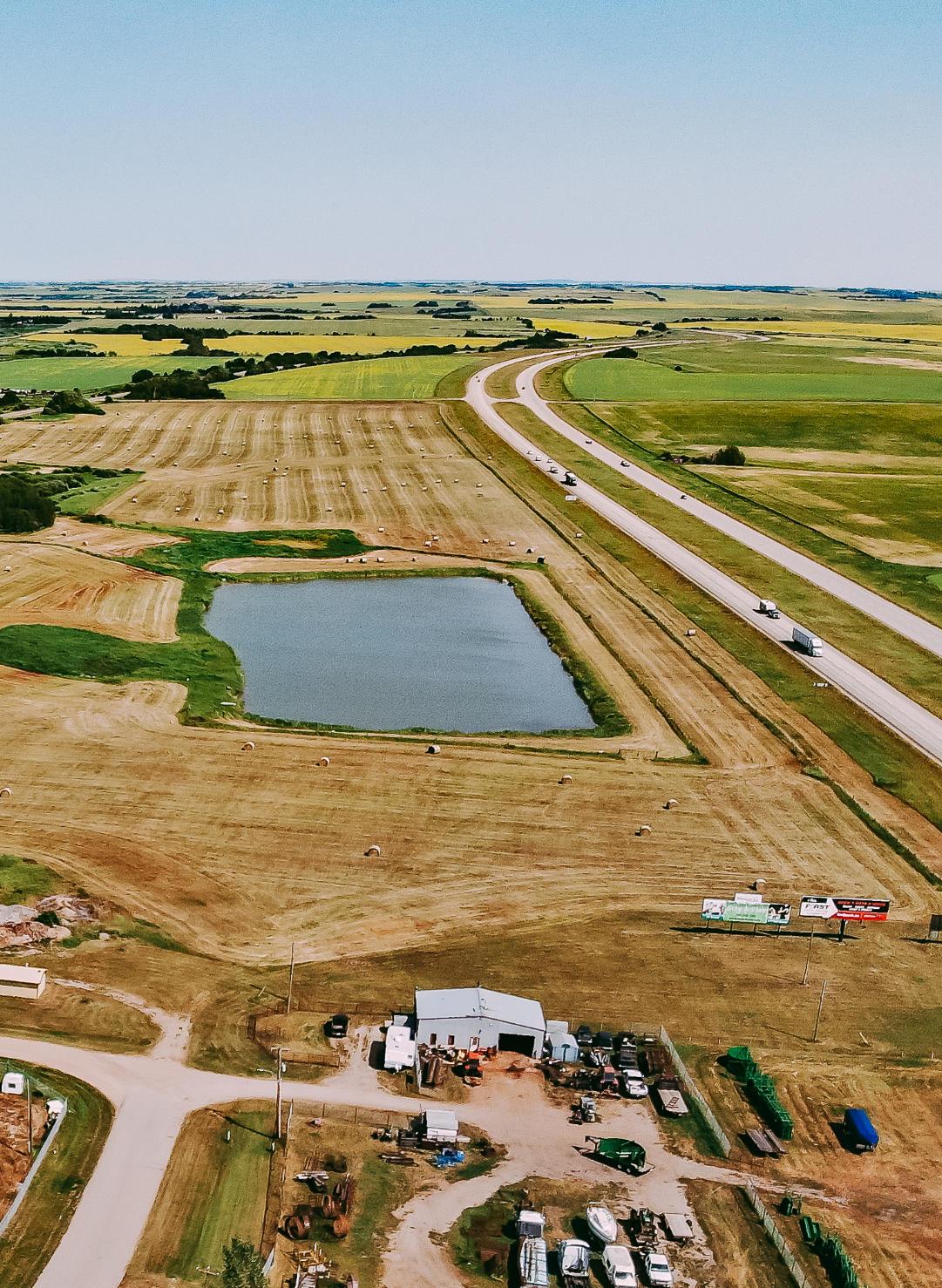
Does not form part of this Bylaw.
Prepared by: BAR Engineering
Contact: Scott Simons. P. Eng. Manager, Municipal Division scott.simons@bareng.ca | 780.875.1683 | BAReng.ca 5237 – 70 Avenue Lloydminster, AB T9V 3N6 January 18, 2023 | BAR Project No.: 22MU-495300 FINAL REPORT
Industrial Park Area Structure Plan (ASP) Stormwater Management Plan County of Minburn No. 27
East
TABLE OF CONTENTS 1.0 INTRODUCTION....................................................................................................1-1 1.1 Background 1-1 1.2 Pre-development Site Description 1-1 1.3 Post Development Description 1-1 2.0 DESIGN CRITERIA AND METHODOLOGY..........................................................2-1 2.1 Design Standards and Assumptions 2-1 2.2 Rainfall Models ............................................................................................2-2 2.3 Horton’s Infiltration Method..........................................................................2-2 2.4 Computer Analysis.......................................................................................2-2 3.0 STORMWATER MANAGEMENT ..........................................................................3-1 3.1 SWM Scenario 1 3-1 3.1.1 Post Development Drainage Patterns 3-1 3.1.2 Proposed Stormwater Management Facilities 3-1 3.1.3 SWMF Modeling Results 3-2 3.1.4 SWMF Drawdown.....................................................................................3-3 3.1.5 Stormwater Quality...................................................................................3-5 3.2 SWM Scenario 2..........................................................................................3-5 3.2.1 Post Development Drainage Patterns and Proposed SWMF ...................3-5 3.2.2 SWMF Modeling Results 3-6 3.2.3 SWMF Drawdown 3-6 3.2.4 Stormwater Quality...................................................................................3-7 3.2.5 Private On-site Stormwater Management 3-7 4.0 CONCLUSIONS AND RECOMMENDATIONS......................................................4-1 Figures
1-1: Location Plan Figure 1-2: Pre Development Drainage
1-3: Development Plan
Figure
Figure
Figure 3-1: Post Development SWMP – Scenario 1
Figure 3-2: Post Development SWMP – Scenario 2
1.0 INTRODUCTION
1.1 Background
Red Willow Planning, on behalf of the County of Minburn No. 27 (County), retained BAR Engineering Co. Ltd. (BAR) to prepare a stormwater management plan (SWMP) to supplement the Area Structure Plan (ASP) for the East Industrial Park. An ASP provides the framework for decision-making regarding future subdivision of the lands, which is utilized by the Municipality and developers for development of the identified area. The SWMP outlines major overland drainage concepts, in context with the ASP and in accordance with applicable design standards and guidelines, to facilitate development of the subject lands. Refinement of the presented stormwater management concepts will occur prior to subdivision of the lands as part of the subdivision phase.
1.2 Pre-development Site Description
The East Industrial Park is located along the east boundary of the Village of Mannville (Mannville, or the Village), which encompasses the east half of the NW ¼ Section 19-50-8-W4M, the NE ¼ Section 19-50-8W4M, and the NE ¼ Section 20-50-8-W4M. The subject ASP parcel is bounded by the Trans Canada Highway 16 to the south, the Village boundary to the west, Township Road 504 to the north and the east quarter section line of the NW ¼ Section 20-50-8-W4M. Canadian National Railway and Mannville Road (formerly Highway 2) bisect the parcel from the northwest corner to the southeast. Figure 1-1 shows the location of the ASP lands.
According to the County’s Land Use Bylaw 1254-16, the existing ASP parcel districts are as follows:
• NW ¼ Section 19-50-8-W4M is zoned Direct Control,
• A small parcel in the southeast corner of the NE ¼ Section 19-50-8-W4M is zoned Rural Commercial District, and
• Remnant of the ASP area is zoned Agricultural.
LiDAR survey data, provided by the County, shows that the subject lands is split into two drainage basins with the drainage divide approximately located along Range Road 85. The NW and NE 19-50-8-W4 generally drain from the north to the south and ultimately discharge via a culvert crossing under Highway 16. Land within the NW20-50-8-W4 slopes from Highway 16 north towards Township Road 504. Figure 12 shows the original ground contours and general flow direction within the property.
1.3 Post Development Description
The ASP development area will be redistricted and subdivided for Rural Industrial land use. Large lot sizes are typical for rural industrial developments, which is consistent with the proposed lotting plan provided by Red Willow Planning. Proposed lot sizes range from roughly 1.00 acres to 9.97 acres as shown in Figure 1-3.
Access to the proposed Rural Industrial lots will be provided via 46 Street, 47A Avenue, Township Road 504, Township Road 503B, and Range Road 85. Local rural cross section industrial lots will be constructed within the proposed development to provide access to the internal lots.
Phasing of the ASP lands has not been identified at this time, although phasing of the development should consider logical implementation and sequencing of the overall drainage and stormwater management system. Further review and refinement of the stormwater management plan will be required
1-1
at the subdivision stage once phasing has been confirmed as the development phasing may impact proposed stormwater management facility (SWMF) locations.
1-2
SE3050-8-4
SW2950-8-4
SE2950-8-4
NW1950-8-4
CANADIANNATIONALRAILWAY
1061JY
NE1950-8-4
HIGHWAY16
NW2050-8-4
3999R
NE2050-8-4
SE1950-8-4
SW2050-8-4
SE2050-8-4
ASPBOUNDARY
VILLAGEOFMANNVILLE RANGE RD 85 HWY 881 TWPRD504
SW1950-8-4
Drawing#: Scale: Drawnby: Date: Approvedby: Revision: 01/16/2023 CMA DJB Figure1-1 1:15000 1 FIGURE1-1:LOCATIONPLAN CountyofMinburnNo.27,Alberta Drawing path: P:\Municipal\22MU-495300 RWP County of Minburn ASP\400-Drawings\Figures\SWMF\22MU-495300Figure 1-1 Location Plan.dwg Layout: Figure 111x17 Figure Last Saved: Jan 18, 20239:25 AM Plotted: January 18, 2023 10:01:22 AM N STORMWATERMANAGEMENTPLAN
SW3050-8-4
NE1950-8-4 1061JY NE1950-8-4 SE30-50-8-4 SW29-50-8-4 SE29-50-8-4 NW1950-8-4
SE1950-8-4
TWPRD503B R A N G E R D 8 5 H W Y 8 8 1 NW1950-8-4 TWPRD504 CANADIANNATIONALRAILWAY 3999R HIGHWAY16 Dawng#: Scae: Drawnby Date Approvedby Revon 01/16/2023 SWS CMAFigure1-2 1:7500 1 FIGURE1-2:PREDEVELOPMENTDRAINAGE STORMWATERMANAGEMENTPLAN CountyofMnburnNo27,Alberta Drawing path: P:\Municipal\22MU-495300 RWP County of Minburn ASP\400-Drawings\Figures\SWMF\22MU-495300Figure 1-2 Pre Development Drainage.dwg Layout: Figure 1-2 Last Saved: Jan 16, 20234:11 PM Plotted: January 18, 2023 10:06:28 AM FLOWDIRECTION
NW2050-8-4 SW2050-8-4
NE2050-8-4 SE2050-8-4 VILLAGEOFMANNVILLE
NE1950-8-4 1061JY NE1950-8-4 SE30-50-8-4 SW29-50-8-4 SE29-50-8-4 NW1950-8-4
SW2050-8-4 SE1950-8-4
TWPRD503B RANGE RD 85 HWY 881 NW1950-8-4 TWPRD504 CANADIANNATIONALRAILWAY 3999R HIGHWAY16 47AAvenue 46 Street Drawing#: Scale: Drawnby: Date: Approvedby: Revision: 01/16/2023 SWS CMA Figure1-3 1:7500 1 FIGURE1-3:DEVELOPMENTPLAN STORMWATERMANAGEMENTPLAN CountyofMinburnNo.27,Alberta Drawing path: P:\Municipal\22MU-495300 RWP County of Minburn ASP\400-Drawings\Figures\SWMF\22MU-495300Figure 1-3 Development Drainage.dwg Layout: Figure 1-3 Last Saved: Jan 18, 20239:37 AM Plotted: January 18, 2023 10:01:51 AM N
ASPBOUNDARY
NW2050-8-4
NE2050-8-4 SE2050-8-4 VILLAGEOFMANNVILLE
2.0 DESIGN CRITERIA AND METHODOLOGY
2.1 Design Standards and Assumptions
Stormwater management regulations and engineering standards have evolved over the past several decades. An approved stormwater management plan (SWMP) must address both stormwater quality and quantity aspects under today’s regulations. The following design guidelines and standards were used in the development of the present stormwater management plan:
• Alberta Environment Standards and Guidelines for Municipal Waterworks, Wastewater and Storm Drainage Systems, Part 5 Stormwater Management Guidelines, March 2013;
• Alberta Environment’s Stormwater Management Drainage Systems Design Guidelines, January 1999; and,
• City of Edmonton Design and Construction Standards, Volume 3 Drainage, February 2022.
• Alberta Transportation Roadside Development Permits
Stormwater runoff volume and discharge rate increase with development of land due to an increase in impervious area from roads, buildings, parking lots, etc. and altering of drainage paths. Stormwater management facilities (SWMFs) are used as a best management practice (BMP) within developments for flood control by temporarily storing and restricting the release rate of stormwater runoff and to provide water quality enhancement prior to discharging to downstream water bodies and watercourses. Wet ponds are commonly used SWMFs as they provide water quality enhancement through settling of runoff pollutants within the permanent pool (dead storage) and stormwater runoff during rain events is temporarily stored above the permanent pool (live or active storage) and released downstream at a restricted rate. Alberta Environment guidelines do not specifically dictate the stormwater quantity requirements; however, they provide the following design parameters:
• 1 in 100 year storm stored within 2m above the permanent pool (alternatively, the 2m can be used to store the 1 in 25 year storm. In such cases an emergency overflow drainage system should be constructed with the capacity to carry storm runoff from the 1 in 100 year storm event to receiving streams or downstream stormwater management facilities); and,
• Detention time of 24 hours.
The 1 in 100 year 24 hour storm design parameter will be adopted for the purposes of quantity control for this SWMP.
Generally, the release rate of a SWMF is restricted to the pre development runoff rate for a parcel of land and is commonly determined using known flow data of downstream watercourses. Matching post development stormwater runoff rate to pre development will mitigate impact on downstream watercourses caused by development. Further analysis of the pre development rate will be required during future subdivision stages and prior to Water Act Application. For the purposes of this SWMP, the following typical release rates have been considered for preliminary SWMF sizing:
• 1 L/s/ha;
• 2.5 L/s/ha;
2-1
• 4 L/s/ha;
• 24-hour drawdown providing available SWMF storage equivalent to runoff from 1:5 year storm;
• 48-hour drawdown providing available SWMF storage equivalent to runoff from 1:25 year storm; and
• 96-hour drawdown providing available SWMF storage equivalent to 90% of total storage volume.
All development adjacent to Alberta Transportation highways require a minimum setback of 70m from the highway centre-line or 40m from the highway right-of-way boundary. The developer will be required to submit a Roadside Development Permit application to Alberta Transportation for the construction of all stormwater management facilities and infrastructure within 800m of the Highway 16 centerline prior to development.
2.2 Rainfall Models
The City of Edmonton Intensity, Duration and Frequency Curves (IDF Curves) were used to develop the storm events to determine the required storage of the SWMF(s). Specifically, required storage was determined using the City of Edmonton’s 1:100 year 24 hour Huff distribution.
2.3 Horton’s Infiltration Method
The infiltration method used in this study was the Horton Infiltration Method, which determines the rate that water seeps through the soil during a storm. This method is based on empirical data that shows that infiltration starts at an initial maximum rate and decreases exponentially to a minimum rate over the course of the rainfall event, which implies that the rate of infiltration decreases as the soil becomes saturated. The infiltration method is described by the following equation:
Where:
fp = infiltration rate at time t (mm/hr)
k = decay rate (1/hr)
fc = minimum equilibrium infiltration rate (mm/hr)
fo = maximum infiltration rate (mm/hr)
The above parameters are based on soil properties and vegetation cover for any basin. For the purposes of this SWMP, it has been assumed that the soil in the study area is comprised of clay loam, lightly vegetated, and moist soil conditions.
2.4 Computer Analysis
To assist in determining runoff rates and design of the Stormwater Management Facilities, a computer model was produced. This model was created using USEPA SWMM 5.0, a dynamic rainfall-runoff simulation model developed by the U.S. Environmental Protection Agency. City of Edmonton rainfall distributions were utilized in the model as previously noted
The post development basin parameters that were used in the computer model are provided in Table 2-1. Post development basins used a combined imperviousness of 72% for the rural industrial lots and subdivision roads, and 100% imperviousness for stormwater management facilities. The impervious area Manning’s ‘n’ of 0.015 is typical for concrete, asphalt, or gravel surfaces and the Manning’s ‘n’ value for pervious areas of 0.10 is typical for short natural grass. Depression storage is the depth of stormwater that
2-2
p = fc + (fo – fc)e-kt
f
is trapped in the basin due to small storage depressions. Impervious areas provide little depression storage, typically ranging in depth from 1.0 to 2.50mm. Pervious areas, like pasture and landscaping, have a much greater potential for depression storage. The Horton Infiltration parameters for the post development basins are described in Section 2.3.
Table 2-1: Basin Parameters
Parameter
Hydraulically Connected Impervious Area:
Impervious Area Manning’s ‘n’
Pervious Area Manning’s ‘n’
Impervious Area Depression Storage 2.0 mm
Pervious Area Depression Storage 5.0 mm
Initial Infiltration Rate, fo 25 mm/hr
Final Infiltration Rate, fc 1.52 mm/hr
Decay Rate of Infiltration 4 /hr
2-3
Post Development
72% 100%
• Rural Industrial Lots • Stormwater Management Facilities
0.015
0.10
3.0 STORMWATER MANAGEMENT
Two stormwater management scenarios have been analyzed for the ASP lands to provide flexibility for development. Scenario 1 includes an overall stormwater management system consisting of interconnected stormwater management facilities for all proposed Rural Industrial lots. The second scenario, Scenario 2, consists of a dedicated stormwater management facility for the smaller Rural Industrial lots located within the NW19-50-5-W4 along the west portion of the East Industrial Park and provision for the remaining larger Rural Industrial lots to provide on-site stormwater management storage. Further description and discussion of these two scenarios is provided in the following sections.
3.1 SWM Scenario 1
3.1.1 Post Development Drainage Patterns
The Canadian National Railway (CN Rail), bisecting the subject lands, will divide the proposed drainage into a north and south catchment. Surface runoff within the north parcel of the NE 19-50-8-W4 will be collected and conveyed via roadside ditches to a proposed dry stormwater management facility located in the northwest corner of the quarter section. The parcel of lands south of the CN Rail will also drain via roadside ditches to a proposed wet stormwater management facility located along the west side of the NE 19-50-8-W4 extending into the southeast corner of the NW19-50-8-W4. Overland flow is designed to run off from the industrial lots to the roadside ditches with minimum 2% lot grades and minimum roadside ditch grades of 0.2%. Two stormwater management facility locations have been identified as shown in Figure 31, however, phasing of the development could result in additional interconnected stormwater management facilities in locations best suited to the phasing of the development. It should be noted that excavated earth from the proposed stormwater management facilities would be used as engineered fill (if suitable) to construct the roadways and proposed lots.
3.1.2 Proposed Stormwater Management Facilities
A dry stormwater management facility (SWMF) has been proposed within the northwest corner of the NE1950-8-W4 and a wet retention pond has been proposed south of the CN Rail. The dry SWMF has been proposed due to the proximity to the CN Rail, however, a wet SWMF could be accommodated pending permitting and approval by CN. Both SWMF’s have been designed in accordance with Alberta Environment guidelines. The following parameters have been utilized in the SWMF design:
Dry Pond (SWMF 1)
• Interior Side Slopes: 4:1 (H:V)
• Maximum Active Storage Depth: 0.9m
• Freeboard Depth: 0.3m
Wet Pond (SWMF 2)
• Interior Side Slopes:
o 7:1 (H:V) from 1m below normal water level (NWL) to the high water level (HWL)
o 3:1 (H:V) side slopes from the pond bottom to 1m below NWL.
• Maximum Active Storage Depth: 0.6m
• Freeboard Depth: 0.6m
Maximum Release Rates
• 83.2 L/s (1 L/s/ha for the 83.2 ha development area)
• 208 L/s (2.5 L/s/ha for the 83.2 ha development area)
3-1
• 332.8 L/s (4 L/s/ha for the 83.2 ha development area)
• 409 L/s (96-hour drawdown providing SWMF storage equivalent to 90% of total volume)
• 508 L/s (48-hour drawdown providing SWMF storage equivalent to the 1:25 year runoff)
• 436 L/s (24-hour drawdown providing SWMF storage equivalent to the 1:5 year runoff)
The SWMF dead storage within a wet retention pond is the volume of water that is permanently stored in the pond and is the storage depth measured from the NWL to the pond bottom. Alberta Environment guidelines require a minimum dead storage depth of 2.0m to mitigate vegetation growth in the pond bottom. Dead storage provides the water quality enhancement of the BMP as previously noted by allowing sediments and pollutants to settle out prior to discharging.
Proposed SWMF 1 has a catchment area of 15.7 ha, as shown in the blue hatch in Figure 3-1. Stormwater from SWMF 1 will be discharged directly to SWMF 2 via a pipe connection. It is important to note that SWMF 1 will be hydraulically connected to SWMF 2 via the pipe connection essentially creating one stormwater management facility. Table 3-1 below provides the surface area and storage volume at the pond bottom, HWL, and freeboard elevations.
Table 3-1: SWMF 1 – Design Parameters
Stormwater runoff from an area of 67.5 ha, shown in the red hatch in Figure 3-1, will drain via roadside ditches to SWMF 2 proposed along the west side of the NE ¼ Section 19-50-8-W4M extending into the NW19-50-8-W4. The entire ASP lands will drain through SWMF 2 across Highway 16 via a stormwater control structure to the natural drainage path in the SE19-50-8-W4M at a controlled release rate providing a hydraulically connected stormwater management system for the entire East Industrial Park development. With SWMF 1 hydraulically connected to SWMF 2, the total catchment area of SWMF 2 is 83.2 ha. Table 3-2 below provides the surface area and storage volume at the pond bottom, NWL, HWL, and freeboard elevations
Table 3-2: SWMF 2 – Design Parameters
3.1.3 SWMF Modeling Results
Computer model simulations were completed for the 100-year rainfall event at the maximum discharge rates identified in Section 3.1.2. Table 3-3 and Table 3-4 summarize the results of the simulation and
3-2
Elevation (m) Surface Area (m2) Volume (m3) Notes 622.30 16,900.4 0.0 Bottom 623.20 18,879.0 16,059.9 HWL 623.50 19,495.8 21,792.6 Freeboard
Elevation (m) Surface Area (m2) Volume (m3) Notes 620.30 103,938.0 0.0 Bottom 622.30 120,158.0 220,775.2 NWL 622.90 127,158.0 294,971.3 HWL 623.50 134,269.0 373,342.8 Freeboard
includes water depth, volume, and outlet discharge as well as the orifice size determined from the computer analysis for the proposed stormwater management facilities.
Table 3-3: SWMF 1 – 24 Hour Rainfall Simulation Results
Discharge Rates does not impact SWMF1 Storage as a result of the interconnecting pipe with SWMF2
Table 3-4: SWMF 2 – 24 Hour Rainfall Simulation Results
3.1.4 SWMF Drawdown
The ability of a SWMF to drawdown in a reasonable amount of time after a storm event has past is an important consideration in design to allow for available capacity within the SWMF for subsequent rainfall events. Alberta Environment does not stipulate drawdown requirements within their guidelines, however, City of Edmonton Design and Construction Standards provide the following parameters:
3-3
SWMF Design Parameter Elevation (m) Pond Volume (m3) Notes 1 Freeboard 623.50 21,792.6 Varying
HWL 623.20 16,059.9 1:100 623.00 12,424.3 Pond Bottom 622.30 0
SWMF Design Parameter Elevation (m) Pond Volume (m3) Peak Discharge Rate (L/s/ha) Outlet Peak Discharge (L/s) Orifice Size (mm) 2 Freeboard 623.50 373,342.8 N/A N/A N/A 1:100 622.92 297,861.3 1 83.2 224 HWL 622.90 294,971.3 N/A N/A N/A 1:100 622.84 287,984.3 2.5 208 366 1:100 622.79 280,426.3 4 332.8 480 1:100 622.76 277,730.1 4.9 409 530 1:100 622.76 276,721 5 5.24 436 550 1:100 622.74 274,280.0 6.1 508 600 NWL 622.30 220,775.2 N/A N/A N/A Pond Bottom 620.30 0 N/A N/A N/A
Time after commencing drawdown from design full level
24 hours
48 hours
Available volume between high water level (HWL) and NWL
Volume equivalent to runoff from 1 in 5 year storm
Volume equivalent to runoff from 1 in 25 year storm
96 hours 90% of total storage volume above NWL
Using a maximum release rate of 2.5 L/s/ha, the above City of Edmonton parameters are not achievable in SWMF 2. Water elevations and volumes at various times after pond drawdown has commenced are provided in Table 3-5, and Table 3-6 for the proposed SWMFs at a maximum release rate of 2.5 L/s/ha. The SWMF volumes at time 0 represents the dead storage capacity or permanent pool volume for the facility.
SWMF 1 would reach a maximum volume of 12,424.3 m3 in 14.0 hours. At 24 hours after pond drawdown has commenced, the live storage is at 53% of maximum capacity. The pond is 90% drained 54 hours after pond drawdown has commenced.
Table 3-5: SWMF 1 Drawdown – 1:100 Year 24-Hour Storm Simulation
SWMF 2 would reach a maximum volume of 287,984.3m3 in 23.2 hours. At 24 hours after pond drawdown has commenced, the live storage is at 87% of maximum capacity. The pond is 90% drained 158.8 hours after pond drawdown has commenced.
Table 3-6: SWMF 2 Drawdown – 1:100 Year 24-Hour Storm Simulation
3-4
Time (hours) Elevation (m) Pond Volume (m3) % of Maximum Live Storage 0 622.3 0 0 14.0 623.00 12,424.3 100 38.0 622.68 6,603.7 53 68.0 622.37 1,242.4 10
Time (hours) Elevation (m) Pond Volume (m3) % of Maximum Live Storage 0 622.3 220,775.2 0 23.2 622.84 287,984.3 100 47.2 622.77 279,123.7 87 182.0 622.35 227,139.4 10
3.1.5 Stormwater Quality
Wet retention ponds are one of Alberta Environment’s best management practices for removing sediments and pollutants from stormwater runoff. Alberta Environment design criteria for stormwater quality control consider storing the volume of runoff from a 25mm 24 hour storm within the dead storage of a wet pond. This provides adequate volume for the removal of sedimentation and pollutants.
A peak elevation of 620.43m was found in SWMF 2 through computer simulation of a 25mm 24-hour storm event. This equates to a depth of 0.13m in the facility with a runoff volume of 13,242m3, which is 6.0% of the dead storage capacity.
3.2 SWM Scenario 2
3.2.1 Post Development Drainage Patterns and Proposed SWMF
Overall drainage patterns for SWM Scenario 2 is similar to Scenario 1 with the main difference being a dedicated stormwater management facility for the smaller lots along the west boundary of the ASP lands and provision for private on-site stormwater management for the larger Rural Industrial lots as shown in Figure 3-2. In addition, stormwaterfrom the proposed lots in the NW20-50-8-W4 will discharge north across Township Road 503B and the CN Rail to the natural discharge point in the northeast corner of the quarter section.
The proposed stormwater management facility is a wet retention pond in the NE19-50-8-W4 and has been designed in accordance with Alberta Environment guidelines. The following parameters have been utilized in the SWMF design:
Wet Pond (SWM Scenario 2 SWMF)
• Interior Side Slopes:
o 7:1 (H:V) from 1m below normal water level (NWL) to the high water level (HWL)
o 3:1 (H:V) side slopes from the pond bottom to 1m below NWL.
• Maximum Active Storage Depth: 0.6m
• Freeboard Depth: 0.6m
• Dead Storage Depth: 2.0m
Maximum Release Rates
• 23.1 L/s (1 L/s/ha for the 23.1 ha development area)
• 57.6 L/s (2.5 L/s/ha for the 23.1 ha development area)
• 92.4 L/s (4 L/s/ha for the 23.1 ha development area)
• 92.4 L/s (96-hour drawdown providing SWMF storage equivalent to 90% of total volume)
• 100 L/s (48-hour drawdown providing SWMF storage equivalent to the 1:25 year runoff)
• 104 L/s (24-hour drawdown providing SWMF storage equivalent to the 1:5 year runoff)
Stormwater runoff from an area of 23.1 ha, shown in the red hatch in Figure 3-2, will drain via roadside ditches to the proposed SWMF in the NW19-50-8-W4. The SWMF, and the proposed lots within the NE1950-8-W4, will drain across Highway 16 to the natural drainage path in the SE19-50-8-W4M. Discharge from the SWMF will be controlled via a control structure at the peak release rate previously noted. Table 3-7 below provides the surface area and storage volume at the pond bottom, NWL, HWL, and freeboard elevations
3-5
Table 3-7: SWM Scenario 2 SWMF – Design Parameters
3.2.2 SWMF Modeling Results
Computer model simulations were completed for the 100-year rainfall event at the maximum discharge rates identified in Section 3.2.1. Table 3-8 summarize the results of the simulation and includes water depth, volume, and outlet discharge as well as the orifice size determined from the computer analysis for the proposed stormwater management facility.
Table 3-8: SWM Scenario 2 SWMF – 24 Hour Rainfall Simulation Results
3.2.3 SWMF Drawdown
Using a maximum release rate of 2.5 L/s/ha, the City of Edmonton SWMF drawdown parameters are not achievable for Scenario 2. Water elevations and volumes at various times after pond drawdown has commenced are provided in Table 3-9 for the proposed SWMF at a maximum release rate of 2.5 L/s/ha. The SWMF volume at time 0 represents the dead storage capacity or permanent pool volume for the facility.
3-6
Elevation (m) Surface Area (m2) Volume (m3) Notes 620.30 34,177.0 0.0 Bottom 622.30 41,453.0 74,080.3 NWL 622.90 44,696.0 99,920.0 HWL 623.50 48,050.0 127,738.0 Freeboard
Design Parameter Elevation (m) Pond Volume (m3) Peak Discharge Rate (L/s/ha) Outlet Peak Discharge (L/s) Orifice Size (mm) Freeboard 623.50 127,738.0 N/A N/A N/A HWL 622.90 99,920.0 N/A N/A N/A 1:100 622.89 99,422.0 1.0 23.1 120 1:100 622.84 97,315.4 2.5 57.6 185 1:100 622.79 95,024.4 4.0 92.2 250 1:100 622.78 94,712.2 4.33 100 260 1:100 622.78 94,562.3 4.51 104 265 NWL 622.30 74,080.3 N/A N/A N/A Pond Bottom 620.30 0 N/A N/A N/A
The SWMF would reach a maximum volume of 97,315.4 m3 in 22.0 hours. At 24 hours after pond drawdown has commenced, the live storage is at 83% of maximum capacity. The pond is 90% drained 166 hours after pond drawdown has commenced.
Table 3-9: SWM Scenario 2 SWMF Drawdown – 1:100 Year 24-Hour Storm Simulation
3.2.4 Stormwater Quality
Wet retention ponds are one of Alberta Environment’s best management practices for removing sediments and pollutants from stormwater runoff. Alberta Environment design criteria for stormwater quality control consider storing the volume of runoff from a 25mm 24 hour storm within the dead storage of a wet pond. This provides adequate volume for the removal of sedimentation and pollutants.
A peak elevation of 620.43m was found in the SWMF through computer simulation of a 25mm 24-hour storm event. This equates to a depth of 0.13m in the facility with a runoff volume of 4,372m3, which is 5.9% of the dead storage capacity.
3.2.5 Private On-site Stormwater Management
Private on-site stormwater storage will be required for all Rural Industrial lots not included within the SWMF catchment area for Scenario 2 in lieu of provision of an overall SWMF to collect and control stormwater runoff. For the purposes of this SWMP, sizing of the individual lot stormwater storage requirements provided in Table 3-10 below is based on a cubic meter per acre volume using the modified Rational Method for the City of Edmonton 24 hour 1:100 year Huff storm and discharge rates of 1 L/s/ha, 2.5 L/s/ha, and 4 L/s/ha.
Table 3-10: SWM Scenario 2 – Private On-site Stormwater Management Storage
It should be noted that these storage volumes are provided for information and planning purposes only. Detailed analysis will be required to size private on-site stormwater management facilities at subdivision and Development Permit stages
3-7
Time (hours) Elevation (m) Pond Volume (m3) % of Maximum Live Storage 0 622.30 74,080.3 0 22.0 622.84 97,315.4 100 46.0 622.75 93,316.0 83 188.0 622.36 76,403.8 10
Discharge Rate (L/s/ha) Required Storage (m3/acre) 1.0 420 2.5 370 4.0 326
SWMF1 SWMF2
PROPOSED STORMSEWER NE1950-8-4 1061JY NE1950-8-4 SE30-50-8-4 SW29-50-8-4 SE29-50-8-4 NW1950-8-4 NW2050-8-4 SW2050-8-4 SE1950-8-4 NE2050-8-4 SE2050-8-4 VILLAGEOFMANNVILLE TWPRD503B RANGE RD 85 HWY 881 NW1950-8-4 TWPRD504 CANADIANNATIONALRAILWAY 3999R HIGHWAY16 FIGURE3-1:POSTDEVELOPMENTSWMP-SCENARIO1 SERVICINGBRIEF CountyofMinburnNo.27,Alberta Drawing path: P:\Municipal\22MU-495300 RWP County of Minburn ASP\400-Drawings\Figures\SWMF\22MU-495300Figure 3-1 Post Development SWMPSCENARIO 1.dwg Layout: Figure 3-3 Servicing Brief Last Saved: Jan 18, 20239:39 AM Plotted: January 18, 2023 10:02:07 N SWMF1CATCHMENTAREA SWMF2CATCHMENTAREA NOTE:SWMFSIZESANDLOCATIONS
DETAILEDDESIGN Drawing#: Scale: Drawnby: Date: Approvedby: Revision: 01/16/2023 SWS CMA Figure3-1 1:7500 1 FLOWDIRECTION
ASPBOUNDARY
SUBJECTTOCHANGEPENDING
ASPBOUNDARY
SUBJECTTOCHANGEPENDING DETAILEDDESIGN
NE1950-8-4 1061JY NE1950-8-4 SE30-50-8-4 SW29-50-8-4 SE29-50-8-4 NW1950-8-4 NW2050-8-4 SW2050-8-4 SE1950-8-4
SE2050-8-4
TWPRD503B RANGE RD 85 HWY 881 NW1950-8-4 TWPRD504 SWMF CANADIANNATIONALRAILWAY 3999R HIGHWAY16
NE2050-8-4
VILLAGEOFMANNVILLE
FIGURE3-2:POSTDEVELOPMENTSWMP-SCENARIO2 SERVICINGBRIEF CountyofMinburnNo.27,Alberta Drawing path: P:\Municipal\22MU-495300 RWP County of Minburn ASP\400-Drawings\Figures\SWMF\22MU-495300Figure 3-2 Post Development SWMPSCENARIO 2.dwg Layout: Figure 3-3 Servicing Brief Last Saved: Jan 18, 20239:58 AM Plotted: January 18, 2023 10:01:15 N SWMFCATCHMENTAREA NOTE:SWMFSIZESANDLOCATIONS
Drawing#: Scale: Drawnby: Date: Approvedby: Revision: 01/16/2023 SWS CMA Figure3-2 1:7500 1 FLOWDIRECTION PRIVATEON-SITESTORMWATER MANAGEMENTREQUIRED
4.0 CONCLUSIONS AND RECOMMENDATIONS
The East Industrial Park ASP area, located in the County of Minburn No. 27, consists of approximately 83.2 ha of rural industrial development. Two stormwater management scenarios have been considered for the ASP lands to provide flexibility in phasing the development. Both scenarios include ditch conveyance and stormwater management facilities to capture stormwater runoff for water quality and quantity control prior to discharging downstream to a natural drainage path. Scenario 1 consists of two SWMFs that collect stormwater runoff from all proposed Rural Industrial lots as where Scenario 2 includes one SWMF to collect runoff from the smaller Rural Industrial lots located in the NW19-50-8-W4 and provision of private on-site stormwater management for all other large Rural Industrial lots.
Consideration was given to various discharge rates in sizing of the proposed SWMFs. Further analysis of the pre-development release rate should be completed at future subdivision stages during detailed stormwater management design. Stormwater runoff simulations were undertaken for various rain events and the stormwater management facilities were sized to accommodate stormwater runoff for the 1:100 year 24-hour City of Edmonton Huff distribution.
In SWM Scenario 1, a dry stormwater management facility has been proposed within the NE19-50-8-W4M due to the proximity to the CN Rail and a wet retention pond has been designed south of the CN Rail with permanent water for enhancement of water quality by allowing sediments and pollutants to settle out in the pond prior to discharging to the downstream watercourse. Configuration of the dry stormwater management facility include 4:1 (H:V) side slopes and 0.3m freeboard depth. The wet retention pond has been designed with 7:1 (H:V) side slopes from 1m below the NWL to freeboard elevation, 3:1 (H:V) side slopes from pond bottom to NWL, minimum 0.6m freeboard depth, and 2.0m permanent pool depth.
A wet retention pond in SWM Scenario 2 has been designed south of the CN Rail within the NW19-50-8W4. Similar to Scenario 1, configuration of the wet retention pond has been designed with 7:1 (H:V) side slopes from 1m below the NWL to freeboard elevation, 3:1 (H:V) side slopes from pond bottom to NWL, minimum 0.6m freeboard depth, and 2.0m permanent pool depth. Private on-site stormwater management storage volumes has been provided for various release rates on a per acre basis. Confirmation of sizing will be required during future subdivision and development permit stages.
Prepared By: BAR Engineering Co. Ltd.
Scott Simons, P. Eng. Manager Municipal Division
Reviewed By,
Caitlin Atkins, P. Eng. Intermediate Engineer Municipal Division
4-1
780.875.1683
5237 - 70 Avenue Lloydminster, AB/SK T9V 3N6
2
G Appendix G Certificates
ofTitle (redacted)
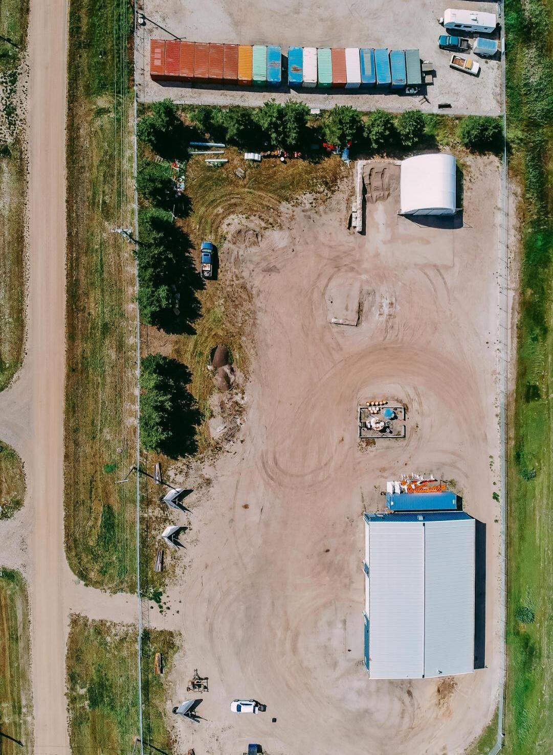
Does not form part of this Bylaw.
S
LINC
0035 392 456
LAND TITLE CERTIFICATE
4;8;50;19;NW,NE
LEGAL DESCRIPTION
MERIDIAN 4 RANGE 8 TOWNSHIP 50
SECTION 19
ALL THAT PORTION OF THE NORTH HALF WHICH LIES NORTH EAST OF RAILWAY RIGHT OF WAY PLAN 3999R CONTAINING 16.08 HECTARES (39.74 ACRES) MORE OR LESS EXCEPTING THEREOUT: HECTARES (ACRES) MORE OR LESS A) PLAN 1223892 ROAD
(N.W. 1/4)
1.03 (N.E. 1/4)
EXCEPTING THEREOUT ALL MINES AND MINERALS AND THE RIGHT TO WORK THE SAME
ESTATE: FEE SIMPLE
MUNICIPALITY: COUNTY OF MINBURN NO. 27
REFERENCE NUMBER:122 322 418
TITLE NUMBER
SHORT LEGAL
132
151 036
0.222
0.415
0.55
CONSIDERATION DOCUMENT TYPE VALUE REGISTERED OWNER(S) 132 151 036 TRANSFER OF LAND $80,000 $80,000 REGISTRATION DATE(DMY) 28/05/2013 OWNERS AND BOTH OF: MANNVILLE ALBERTA AS JOINT TENANTS ( CONTINUED )
REGISTRATION NUMBER
DATE (D/M/Y) PARTICULARS
862 005 167
09/01/1986
UTILITY RIGHT OF WAY
862 005 168
09/01/1986
902 243 518
17/08/1990
TOTAL INSTRUMENTS:
003
2 PAGE # 132 151 036
GRANTEE - ALBERTA GOVERNMENT TELEPHONES. "N.W. PART AS DESCRIBED"
UTILITY RIGHT OF WAY
GRANTEE - ALBERTA GOVERNMENT TELEPHONES. "N.E. PART AS DESCRIBED"
UTILITY RIGHT OF WAY
GRANTEE - MINCO GAS CO-OP LTD. AS TO NE
THE REGISTRAR OF TITLES CERTIFIES THIS TO BE AN ACCURATE REPRODUCTION OF THE CERTIFICATE OF TITLE REPRESENTED HEREIN THIS 13 DAY OF JUNE, 2023 AT 01:12 P.M.
ORDER NUMBER:
CUSTOMER FILE NUMBER: 47502069
*END OF CERTIFICATE*

THIS ELECTRONICALLY TRANSMITTED LAND TITLES PRODUCT IS INTENDED FOR THE SOLE USE OF THE ORIGINAL PURCHASER, AND NONE OTHER, SUBJECT TO WHAT IS SET OUT IN THE PARAGRAPH BELOW.
THE ABOVE PROVISIONS DO NOT PROHIBIT THE ORIGINAL PURCHASER FROM INCLUDING THIS UNMODIFIED PRODUCT IN ANY REPORT, OPINION, APPRAISAL OR OTHER ADVICE PREPARED BY THE ORIGINAL PURCHASER AS PART OF THE ORIGINAL PURCHASER APPLYING PROFESSIONAL, CONSULTING OR TECHNICAL EXPERTISE FOR THE BENEFIT OF CLIENT(S).
ENCUMBRANCES, LIENS & INTERESTS
LINC
0013 955 829
LAND TITLE CERTIFICATE
4;8;50;20;NW
LEGAL DESCRIPTION
ALL THAT PORTION OF THE NORTH WEST QUARTER OF SECTION TWENTY (20)
TOWNSHIP FIFTY (50)
RANGE EIGHT (8) WEST OF THE FOURTH MERIDIAN
LYING NORTH OF THE NORTH BOUNDARY OF A RAILROAD AS SHOWN ON PLAN OF SURVEY 3999R CONTAINING 29 HECTARES (72 ACRES) MORE OR LESS
EXCEPTING THEREOUT ALL MINES AND MINERALS
ESTATE: FEE SIMPLE
MUNICIPALITY: COUNTY OF MINBURN NO. 27
REFERENCE NUMBER:812 191 843
S
TITLE NUMBER SHORT LEGAL
902 244 497
CONSIDERATION DOCUMENT TYPE VALUE REGISTERED OWNER(S) 902 244 497 TRANSFER OF LAND $30,000 $1 REGISTRATION DATE(DMY) 17/08/1990 OWNERS AND BOTH OF: MANNVILLE ALBERTA ( CONTINUED )
REGISTRATION NUMBER
DATE (D/M/Y) PARTICULARS
2 PAGE # 902 244 497
802 019 983
29/01/1980
CAVEAT
CAVEATOR - PARAMOUNT ENERGY OPERATING CORP. ATTN: LAND MANAGER BOX 2776, STATION M CALGARY
ALBERTA T2P3C2
(DATA UPDATED BY: TRANSFER OF CAVEAT 932102705)
(DATA UPDATED BY: TRANSFER OF CAVEAT 932237464)
(DATA UPDATED BY: CHANGE OF NAME 062264351)
(DATA UPDATED BY: TRANSFER OF CAVEAT 072573424)
(DATA UPDATED BY: CHANGE OF ADDRESS 082117367)
862 006 623
13/01/1986
UTILITY RIGHT OF WAY GRANTEE - ALBERTA GOVERNMENT TELEPHONES. "PART"
902 232 387
07/08/1990
UTILITY RIGHT OF WAY GRANTEE - MINCO GAS CO-OP LTD. 003
THE REGISTRAR OF TITLES CERTIFIES THIS TO BE AN ACCURATE REPRODUCTION OF THE CERTIFICATE OF TITLE REPRESENTED HEREIN THIS 13 DAY OF JUNE, 2023 AT 01:14 P.M.
ORDER NUMBER:
CUSTOMER FILE NUMBER: 47502101
TOTAL INSTRUMENTS: *END OF CERTIFICATE*
THIS ELECTRONICALLY TRANSMITTED LAND TITLES PRODUCT IS INTENDED FOR THE SOLE USE OF THE ORIGINAL PURCHASER, AND NONE OTHER, SUBJECT TO WHAT IS SET OUT IN THE PARAGRAPH BELOW.
THE ABOVE PROVISIONS DO NOT PROHIBIT THE ORIGINAL PURCHASER FROM INCLUDING THIS UNMODIFIED PRODUCT IN ANY REPORT, OPINION, APPRAISAL OR OTHER ADVICE PREPARED BY THE ORIGINAL PURCHASER AS PART OF THE ORIGINAL PURCHASER APPLYING PROFESSIONAL, CONSULTING OR TECHNICAL EXPERTISE FOR THE BENEFIT OF CLIENT(S).
ENCUMBRANCES, LIENS & INTERESTS
S
LINC
0032 011 950
LAND TITLE CERTIFICATE
TITLE NUMBER SHORT LEGAL
082 185 488 +1 0626818;1;1
LEGAL DESCRIPTION
DESCRIPTIVE PLAN 0626818
BLOCK 1 LOT 1
EXCEPTING THEREOUT ALL MINES AND MINERALS AREA: 13.5 HECTARES (33.36 ACRES) MORE OR LESS
ATS REFERENCE: 4;8;50;20;NW
ESTATE: FEE SIMPLE
MUNICIPALITY: COUNTY OF MINBURN NO. 27
REFERENCE NUMBER:062 501 667
REGISTERED OWNER(S)
REGISTRATION DATE(DMY)
082 185 488
OWNERS OF MANNVILLE
02/05/2008
CONSIDERATION
TRANSFER OF LAND SEE INSTRUMENT
ENCUMBRANCES, LIENS & INTERESTS
REGISTRATION NUMBER
DATE (D/M/Y) PARTICULARS
UTILITY RIGHT OF WAY 24/05/1963
2162NI GRANTEE - ALBERTA POWER LIMITED. "DATA UPDATED BY TRANSFER OF UTRW NO. 6699SQ PART"
02/11/2006
062 501 666 CAVEAT RE : ACQUISITION OF LAND CAVEATOR - THE COUNTY OF MINBURN NO. 27.
( CONTINUED )
TYPE VALUE
DOCUMENT
ALBERTA
REGISTRATION NUMBER
DATE (D/M/Y) PARTICULARS
P.O. BOX 550
VEGREVILLE
ALBERTA T9C1R6
062 501 668
02/11/2006
CAVEAT
RE : DEFERRED RESERVE
082 185 489
02/05/2008
TOTAL INSTRUMENTS:
2 PAGE # 082 185 488 +1
CAVEATOR - THE COUNTY OF MINBURN NO. 27. BOX 550, 4909-50 ST VEGREVILLE
ALBERTA T9C1R6
MORTGAGE
MORTGAGEE - CANADIAN IMPERIAL BANK OF COMMERCE.
4940-50 AVE
VERMILION
ALBERTA T9X1A4
ORIGINAL PRINCIPAL AMOUNT: $140,000 004
THE REGISTRAR OF TITLES CERTIFIES THIS TO BE AN ACCURATE REPRODUCTION OF THE CERTIFICATE OF TITLE REPRESENTED HEREIN THIS 13 DAY OF JUNE, 2023 AT 01:14 P.M.
ORDER NUMBER:
CUSTOMER FILE NUMBER: 47502108
*END OF CERTIFICATE*
THIS ELECTRONICALLY TRANSMITTED LAND TITLES PRODUCT IS INTENDED FOR THE SOLE USE OF THE ORIGINAL PURCHASER, AND NONE OTHER, SUBJECT TO WHAT IS SET OUT IN THE PARAGRAPH BELOW.
THE ABOVE PROVISIONS DO NOT PROHIBIT THE ORIGINAL PURCHASER FROM INCLUDING THIS UNMODIFIED PRODUCT IN ANY REPORT, OPINION, APPRAISAL OR OTHER ADVICE PREPARED BY THE ORIGINAL PURCHASER AS PART OF THE ORIGINAL PURCHASER APPLYING PROFESSIONAL, CONSULTING OR TECHNICAL EXPERTISE FOR THE BENEFIT OF CLIENT(S).
ENCUMBRANCES, LIENS & INTERESTS
S
LINC
0038 962 536
LAND TITLE CERTIFICATE
SHORT LEGAL
212 218 373 2122252;1;1
LEGAL DESCRIPTION PLAN 2122252
BLOCK 1 LOT 1
EXCEPTING THEREOUT ALL MINES AND MINERALS AREA: 4.047 HECTARES (10 ACRES) MORE OR LESS
ESTATE: FEE SIMPLE
ATS REFERENCE: 4;8;50;19;NE
MUNICIPALITY: COUNTY OF MINBURN NO. 27
REFERENCE NUMBER:072 513 616 +1
REGISTRATION DATE(DMY) 06/10/2021
CONSIDERATION
212 218 373
OWNERS
TITLE NUMBER
VALUE
DOCUMENT TYPE
REGISTERED OWNER(S)
SUBDIVISION PLAN
BOTH OF: MANNVILLE ALBERTA AS JOINT TENANTS DATE (D/M/Y) PARTICULARS ENCUMBRANCES, LIENS & INTERESTS REGISTRATION ----------------------------------------------------------------------------NUMBER UTILITY RIGHT OF WAY 06/02/1989 892 028 071 GRANTEE - MINCO GAS CO-OP LTD. ( CONTINUED )
AND
REGISTRATION NUMBER
DATE (D/M/Y) PARTICULARS
2 PAGE # 212 218 373
122 419 438
20/12/2012
MORTGAGE
MORTGAGEE - THE TORONTO DOMINION BANK. 500 EDMONTON CITY CENTER EAST, 10205-101 STREET, 5TH FLOOR
EDMONTON
ALBERTA T5J5E8
ORIGINAL PRINCIPAL AMOUNT: $410,500
162 337 294
29/11/2016
MORTGAGE
MORTGAGEE - THE TORONTO DOMINION BANK. 500 EDMONTON CITY CENTRE EAST 10205- 101ST STREET, 5TH FLOOR
EDMONTON
ALBERTA T5J5E8
TOTAL INSTRUMENTS:
ORIGINAL PRINCIPAL AMOUNT: $410,500 003
THE REGISTRAR OF TITLES CERTIFIES THIS TO BE AN ACCURATE REPRODUCTION OF THE CERTIFICATE OF TITLE REPRESENTED HEREIN THIS 13 DAY OF JUNE, 2023 AT 01:11 P.M.
ORDER NUMBER:
CUSTOMER FILE NUMBER: 47502027
*END OF CERTIFICATE*
THIS ELECTRONICALLY TRANSMITTED LAND TITLES PRODUCT IS INTENDED FOR THE SOLE USE OF THE ORIGINAL PURCHASER, AND NONE OTHER, SUBJECT TO WHAT IS SET OUT IN THE PARAGRAPH BELOW.
THE ABOVE PROVISIONS DO NOT PROHIBIT THE ORIGINAL PURCHASER FROM INCLUDING THIS UNMODIFIED PRODUCT IN ANY REPORT, OPINION, APPRAISAL OR OTHER ADVICE PREPARED BY THE ORIGINAL PURCHASER AS PART OF THE ORIGINAL PURCHASER APPLYING PROFESSIONAL, CONSULTING OR TECHNICAL EXPERTISE FOR THE BENEFIT OF CLIENT(S).
ENCUMBRANCES, LIENS & INTERESTS
LINC
LAND TITLE CERTIFICATE
0018 183 178 072 513 616 4;8;50;19;NW
LEGAL DESCRIPTION
ALL THAT PORTION OF THE NORTH WEST QUARTER OF SECTION NINETEEN (19)
TOWNSHIP FIFTY (50)
RANGE EIGHT (8)
WEST OF THE FOURTH MERIDIAN
WHICH LIES NORTH OF ROAD PLAN 8420925, EAST OF SUBDIVISION PLAN 8520860 AND SOUTH OF ROAD PLAN 1061JY CONTAINING 19.9 HECTARES (49.27 ACRES)
MORE OR LESS
EXCEPTING THEREOUT ALL MINES AND MINERALS AND THE RIGHT TO WORK THE SAME
ESTATE: FEE SIMPLE
MUNICIPALITY: COUNTY OF MINBURN NO. 27
REFERENCE NUMBER:012 072 384
REGISTRATION DATE(DMY)
072 513 616
CONSIDERATION
S
TITLE
SHORT LEGAL
NUMBER
DOCUMENT
VALUE
TYPE
REGISTERED OWNER(S)
TRANSFER OF LAND SEE INSTRUMENT
25/08/2007 OWNERS AND BOTH OF: MANNVILLE ALBERTA AS JOINT TENANTS ( CONTINUED )
REGISTRATION NUMBER
DATE (D/M/Y) PARTICULARS
2 PAGE # 072 513 616
390JU
20/08/1954
UTILITY RIGHT OF WAY
GRANTEE - ATCO GAS AND PIPELINES LTD.
10035-105 ST
EDMONTON
ALBERTA T5J2V6
AS TO PORTION OR PLAN:5943HW (DATA UPDATED BY: TRANSFER OF UTILITY RIGHT OF WAY 012026215)
7748LI
20/07/1959
UTILITY RIGHT OF WAY
GRANTEE - ALBERTA POWER LIMITED. AS TO PORTION OR PLAN:5943HW "DATA UPDATED BY: TRANSFER OF UTILITY RIGHT OF WAY #6699SQ"
792 136 874
15/06/1979
UTILITY RIGHT OF WAY
GRANTEE - ALBERTA POWER LIMITED.
872 122 589
02/06/1987
UTILITY RIGHT OF WAY
GRANTEE - THE VILLAGE OF MANNVILLE. AS TO PORTION OR PLAN:8721438
882 076 453
14/04/1988
UTILITY RIGHT OF WAY
GRANTEE - ATCO GAS AND PIPELINES LTD. 10035-105 ST
EDMONTON
ALBERTA T5J2V6 (DATA UPDATED BY: TRANSFER OF UTILITY RIGHT OF WAY 012019921)
142 098 440
03/04/2014
DISCHARGE OF UTILITY RIGHT OF WAY 882076453 PARTIAL EXCEPT PLAN/PORTION: 8721438
THE REGISTRAR OF TITLES CERTIFIES THIS TO BE AN ACCURATE REPRODUCTION OF THE CERTIFICATE OF TITLE REPRESENTED HEREIN THIS 13 DAY OF JUNE, 2023 AT 01:09 P.M.
ORDER NUMBER:
CUSTOMER FILE NUMBER: 47501988
CONTINUED )
ENCUMBRANCES, LIENS & INTERESTS
006 TOTAL INSTRUMENTS:
*END OF CERTIFICATE*
(
THIS ELECTRONICALLY TRANSMITTED LAND TITLES PRODUCT IS INTENDED FOR THE SOLE USE OF THE ORIGINAL PURCHASER, AND NONE OTHER, SUBJECT TO WHAT IS SET OUT IN THE PARAGRAPH BELOW.
THE ABOVE PROVISIONS DO NOT PROHIBIT THE ORIGINAL PURCHASER FROM INCLUDING THIS UNMODIFIED PRODUCT IN ANY REPORT, OPINION, APPRAISAL OR OTHER ADVICE PREPARED BY THE ORIGINAL PURCHASER AS PART OF THE ORIGINAL PURCHASER APPLYING PROFESSIONAL, CONSULTING OR TECHNICAL EXPERTISE FOR THE BENEFIT OF CLIENT(S).
PAGE # 072 513 616 3
LINC
0038 962 544
LAND TITLE CERTIFICATE
4;8;50;19;NE
LEGAL DESCRIPTION
MERIDIAN 4 RANGE 8 TOWNSHIP 50
SECTION 19
ALL THAT PORTION OF THE NORTH EAST QUARTER WHICH LIES TO THE SOUTH OF ROAD PLAN 1061JY AND NORTH OF ROAD PLAN 8420925
CONTAINING 26.6 HECTARES (65.85 ACRES) MORE OR LESS EXCEPTING THEREOUT: HECTARES (ACRES) MORE OR LESS
A) PLAN 9420258 ROAD
B) PLAN 2122252 SUBDIVISION
0.32
C) PLAN 2122253 ROAD 0.105 0.26 EXCEPTING THEREOUT ALL MINES AND MINERALS AND THE RIGHT TO WORK THE SAME
ESTATE: FEE SIMPLE
MUNICIPALITY: COUNTY OF MINBURN NO. 27 REFERENCE
S
TITLE NUMBER SHORT LEGAL
212 218 378
0.130
4.047 10.00
NUMBER:212 218 373 +1 CONSIDERATION DOCUMENT TYPE VALUE REGISTERED OWNER(S) 212 218 378 ROAD PLAN REGISTRATION DATE(DMY) 06/10/2021 OWNERS AND BOTH OF: MANNVILLE ALBERTA AS JOINT TENANTS ( CONTINUED )
REGISTRATION NUMBER
DATE (D/M/Y) PARTICULARS
892 028 071
06/02/1989
UTILITY RIGHT OF WAY
GRANTEE - MINCO GAS CO-OP LTD.
20/12/2012 122 419 438
MORTGAGE
29/11/2016 162 337 294
TOTAL INSTRUMENTS:
2 PAGE # 212 218 378
MORTGAGEE - THE TORONTO DOMINION BANK.
500 EDMONTON CITY CENTER EAST, 10205-101 STREET, 5TH FLOOR
EDMONTON
ALBERTA T5J5E8
ORIGINAL PRINCIPAL AMOUNT: $410,500
MORTGAGE
MORTGAGEE - THE TORONTO DOMINION BANK.
500 EDMONTON CITY CENTRE EAST
10205- 101ST STREET, 5TH FLOOR
EDMONTON
ALBERTA T5J5E8
ORIGINAL PRINCIPAL AMOUNT: $410,500
THE REGISTRAR OF TITLES CERTIFIES THIS TO BE AN ACCURATE REPRODUCTION OF THE CERTIFICATE OF TITLE REPRESENTED HEREIN THIS 13 DAY OF JUNE, 2023 AT 01:10 P.M.
ORDER NUMBER:
CUSTOMER FILE NUMBER: 47502019
*END OF CERTIFICATE*
THIS ELECTRONICALLY TRANSMITTED LAND TITLES PRODUCT IS INTENDED FOR THE SOLE USE OF THE ORIGINAL PURCHASER, AND NONE OTHER, SUBJECT TO WHAT IS SET OUT IN THE PARAGRAPH BELOW.
THE ABOVE PROVISIONS DO NOT PROHIBIT THE ORIGINAL PURCHASER FROM INCLUDING THIS UNMODIFIED PRODUCT IN ANY REPORT, OPINION, APPRAISAL OR OTHER ADVICE PREPARED BY THE ORIGINAL PURCHASER AS PART OF THE ORIGINAL PURCHASER APPLYING PROFESSIONAL, CONSULTING OR TECHNICAL EXPERTISE FOR THE BENEFIT OF CLIENT(S).
ENCUMBRANCES, LIENS & INTERESTS
003
S
LINC
0011 057 213
LAND TITLE CERTIFICATE
TITLE NUMBER SHORT LEGAL
852 128 361 8520860;A
LEGAL DESCRIPTION
PLAN 8520860
BLOCK (A)
CONTAINING 22.26 HECTARES (55.01 ACRES) MORE OR LESS
EXCEPTING THEREOUT: 18.7 HECTARES (46.21 ACRES) MORE OR LESS SUBDIVIDED UNDER PLAN 8720202
EXCEPTING THEREOUT ALL MINES AND MINERALS
ATS REFERENCE: 4;8;50;19;NW
ESTATE: FEE SIMPLE
MUNICIPALITY: VILLAGE OF MANNVILLE
REGISTERED OWNER(S)
REGISTRATION DATE(DMY)
DOCUMENT TYPE VALUE
CONSIDERATION
852 128 361 $89,000
OWNERS
24/06/1985
ENCUMBRANCES, LIENS & INTERESTS
REGISTRATION NUMBER
DATE (D/M/Y) PARTICULARS
20/07/1959
UTILITY RIGHT OF WAY
7748LI GRANTEE - ALBERTA POWER LIMITED. "DATA UPDATED BY TRANSFER OF UTRW 6699SQ; REGISTRATION NUMBER CORRECTED" (DATA UPDATED BY: 062550759 )
792 136 874
15/06/1979
UTILITY RIGHT OF WAY GRANTEE - ALBERTA POWER LIMITED. ( CONTINUED )
.
REGISTRATION NUMBER
DATE (D/M/Y)
872 122 591
02/06/1987
UTILITY RIGHT OF WAY
GRANTEE - THE VILLAGE OF MANNVILLE. AS TO PORTION OR PLAN:8721438
2 PAGE # 852 128 361
882 057 506
21/03/1988
UTILITY RIGHT OF WAY
GRANTEE - ATCO GAS AND PIPELINES LTD. 10035-105 ST EDMONTON
ALBERTA T5J2V6
(DATA UPDATED BY: TRANSFER OF UTILITY RIGHT OF WAY 012019911)
972 297 573
30/09/1997
CAVEAT
RE : RIGHT OF WAY AGREEMENT
CAVEATOR - ALBERTA POWER LIMITED. ATTENTION: LAND & PROPERTIES 10035-105 STREET EDMONTON
ALBERTA T5J2V6 AGENT - LORRIE SAWCHUK
142 098 441
03/04/2014
DISCHARGE OF UTILITY RIGHT OF WAY 882057506 PARTIAL EXCEPT PLAN/PORTION: 8721438
THE REGISTRAR OF TITLES CERTIFIES THIS TO BE AN ACCURATE REPRODUCTION OF THE CERTIFICATE OF TITLE REPRESENTED HEREIN THIS 13 DAY OF JUNE, 2023 AT 01:17 P.M.
ORDER NUMBER:
47502166
CUSTOMER FILE NUMBER:
*END OF CERTIFICATE*
ENCUMBRANCES, LIENS & INTERESTS
PARTICULARS
006 TOTAL INSTRUMENTS:
( CONTINUED )
THIS ELECTRONICALLY TRANSMITTED LAND TITLES PRODUCT IS INTENDED FOR THE SOLE USE OF THE ORIGINAL PURCHASER, AND NONE OTHER, SUBJECT TO WHAT IS SET OUT IN THE PARAGRAPH BELOW.
THE ABOVE PROVISIONS DO NOT PROHIBIT THE ORIGINAL PURCHASER FROM INCLUDING THIS UNMODIFIED PRODUCT IN ANY REPORT, OPINION, APPRAISAL OR OTHER ADVICE PREPARED BY THE ORIGINAL PURCHASER AS PART OF THE ORIGINAL PURCHASER APPLYING PROFESSIONAL, CONSULTING OR TECHNICAL EXPERTISE FOR THE BENEFIT OF CLIENT(S).
PAGE # 852 128 361 3
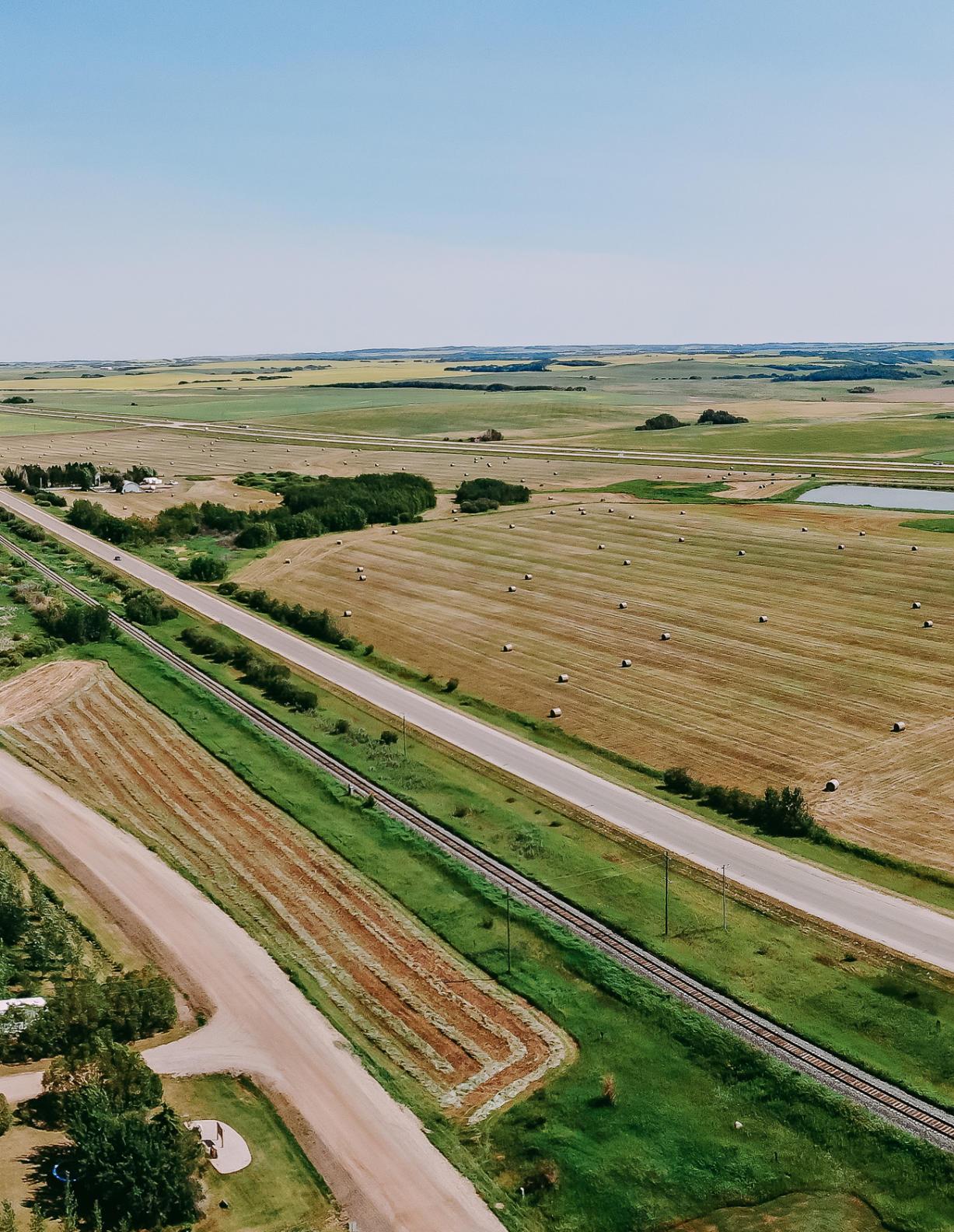 Prepared by Red Willow Planning
All photos by Davin Gegolick
Prepared by Red Willow Planning
All photos by Davin Gegolick
East Industrial Park Area Structure Plan
