
FileName
Page 1/22
5MWh20ftliquidcooledcontainerenergystoragesystemspecification
Name:5MWh20ftliquidcooledcontainerenergystoragesystem
Model
Prepared Checked Approved
ZhangqingYu QisiDeng
GuanghuiZhang
FileName
ProductSpecification Page 2/22
RevisionHistory
RevRevisedcontentdescriptionDateofissueRevisedbyCheckedbyApprovedby
A/1 Firstedition 20240926
A/2
Secondedition,technicalterm, inset 20250225
ZhangqingYu、 PeifengWu QisiDengGuanghuiZhang
ZhangqingYu、 PeifengWu QisiDengGuanghuiZhang
FileName ProductSpecification Page 4/22
1.Termsdefinition
Table1:Termsdefinition
RJETech GuangzhouRongjieEnergyTechnologyCo.,Ltd
LFP LithiumIronPhosphate
AC AlternatingCurrent
DC DirectCurrent
BMS BatteryManagementSystem
BMU BatteryManagementUnit
BCMU BatteryClusterManagementUnit
BSMU BatterySystemManagementUnit
BOL BeginOfLife
EOL EndOfLife
HVBox HighVoltageControlBox
MSD ManualServiceDisconnect
PCS PowerConversionSystem
SOC StateOfCharge
SOH StateOfHealth
SOE StateOfEnergy
SOP StateOfPower
UPS UninterruptiblePowerSupply
CCS CellConnectionSystem
CAN ControllerAreaNetwork
ETH EthernetModule
PDB PowerDistributionBox
DCCB DCCombinerBox
HVAC HeatingVentilationAirConditioning
MCCB MoldedCaseCircuitBreaker
FileName ProductSpecification Page 5/22
2.Productintroduction
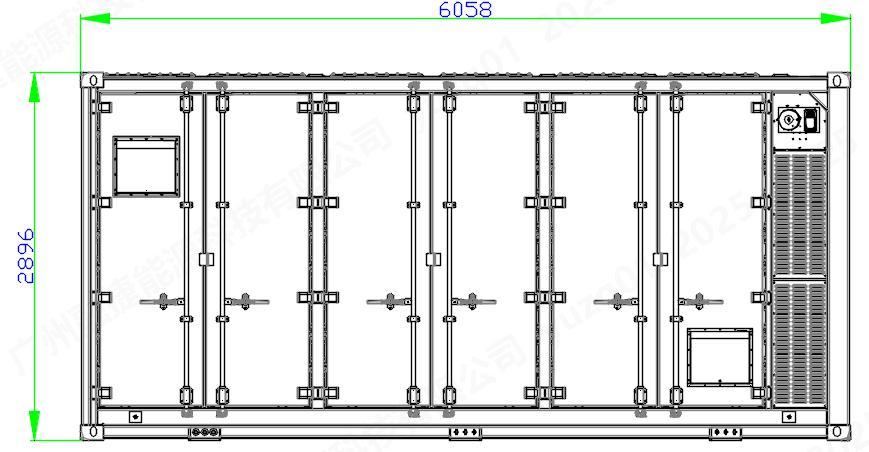
The5MWh20ftliquidcooledcontainerenergystoragesystemconsistsof12clustersof13312V/314Ahbattery cluster,PDB,DCCB,fireprotectionsystem,batterymanagementsystem,andthermalmanagementsystemThesystem outlinediagramisshowninfigure1
Adoptingstandardnon-walk-in20ftcontainer,themodulardesignenhancestheutilizationofspaceinthecontainer.
Theadvancedliquidcoolingcycledesignconceptenablesthebatterysystemtoperformoptimally;thethree-level intelligentbatterymanagementsystemminimizestheriskofthermalrunawayofthesystem,whicheffectivelyimprovesthe all-roundsafetyoftheenergystoragesystemandthelifecycleofthestoragebattery,andprovidesasafertechnical guaranteefortheoperationoftheenergystoragesystem.


2.1Electricaldiagramofcontainertopology
Thecontainersystemadoptsanintegratedsolution
PCSadoptsacentralizedsolution,with12clustersofbatteriespassingthroughahighvoltagecontrolboxandaDCCB, connectedtoonePCSmoduleinputterminal,asshowninfigure2.

:Electricaldiagramofcontainertopology
FileName
2.2BMS
ProductSpecification Page 6/22
Thewholebatterymanagementsystemincludesthreelevelsofarchitecture,whicharefirstlevelslavecontroller, secondlevelmastercontrollerandthirdlevelsystemcontroller,andthefunctionsatalllevelsareshowninfigure3The mainprotectionparametersaredetailedinthe“BMStechnicalprotocol”.

2.3Parametersofcontainer
Thetechnicalparametersofthisproductarebasedonthemeasurementresultsofnewmodulesorbatteriesatroom temperatureof25±2℃.
Table2:Parametersofcontainer No.
1Configuration 1P416S×12 12-clusterspara
2Ratedvoltage 13312V Standardchargeanddischarge
3Ratedenergy 5015MWh Standardchargeanddischarge
4Voltagerange 11648-14976VDC
5Ratedcharge/dischargepower0.5P
6Operatingtemperaturerange-30~55℃(discharge) -3055℃(charge)
Charge:15~35℃ Discharge:0~45℃
Heatingfirstbeforecharging whenbelow0℃
7SOC(%) 30% (25±2)℃
FileName
8AdaptivePCS
Storage condition
10General parameters
ProductSpecification Page 7/22
CentralizedtypePCS
Storage temperature 0~45℃
Storagehumidity5%≤RH≤90%
Altitude ≤2500m >2500mDeratedoperation
Dimension6058×2438×2896mm W×L×H
Weight 42.5t
IPlevel IP55
Thermal managementLiquidcooled
Communication interface CAN\RS485\Ethernet
Communication protocol Modbus\IEC61850
11CertificationContainer
2.4Containerkeycomponentslist
IEC62619/EN61000-6-2/4EN62477-1/UN383/NFPA68/ IEEE693/UL9540A/UL1973/IEC62933/ANSIC634&47CFR PART15B
Table3:Containerkeycomponentslist
Component Quantit y
Batteryrack 6setTwoclustersinonerack,totally12clusters
Batterymodule 48pcs1P104Sinonemodule
HVBox 6pcs
Thermalmanagementsystem 1set
Fireprotectionsystem 1set
Includingisolationswitch,Fuse,Relay, Switchingpowersupply,Pre-chargeresistance
Includingchillerhost,liquidcoolingplate,cooling pipeandHVAC
Aerosolfireprotectionsystem,includingdetector, fireprotectioncontrolhostandpipe
Waterfireprotectionsystem,includingpipeand sprinkler
PDB 1setAuxiliarypowersupply
DCCB 1setContainerlevelDCbusbar
BMS 1setBSMU(includingdisplay),BCMU,BMU
FileName ProductSpecification
3.Keycomponentparameters
3.1Cell
3.1.1Parametersofcell
Table4:Parametersofcell
No. Item Parameter
1Celltype LFP
2Cellmodel RBA4F1
Page 8/22
Remark
3Cellweight 57±03kg Wrappedinbluefilm
4InternalresistanceofBOL 0.18±0.05mΩ 30%SOC,1kHz
5Nominalcapacity 314Ah (25±2)℃,Standardchargeand discharge
6Nominalvoltage 32V (25±2)℃,
7Ratedenergy 1004.8Wh (25±2)℃,
8Operatingvoltage 2.50~3.65V 200~365V T>0℃ T≤0℃
9Energydensity ≥177.8Wh/kg (25±2)℃,Standardchargeand discharge
10SOCrecommended 5%~95%
11Monthlyself-discharge ≤30%
12
13
NewcellsofEOL,25±2℃, 30%SOC,storagefor3months
Maximumcontinuouscharging power 0.5P Charge:15~35℃
Maximumcontinuousdischarge power 05P Discharge:0~45℃
14Dischargetemperaturerange-20~55℃
15Chargetemperaturerange 0~55℃
Note:Thethicknessismeasuredatasurfacepressureof5000±200N
Celldetailedparameterscanbereferencedin“314AhCellProductSpecification”
Heatingfirstbeforecharging whenbelow0℃
FileName
3.1.2Dimensionsofcell
1Height(excludingpole)
2Height(includingpole)
3Thickness
4 Width
5Weldingareaofpole
Table5:Dimensionsofcell
Page 9/22
204.4mm(includinginsulationfilm, includingoutergasket) ±0.6mm
2068mm(includinginsulationfilm)±05mm
71.55mm(includinginsulationfilm)±0.5mm
17426mm(Thebottomhemofthe cell,includinginsulationfilm) ±005mm
174.04mm(Themiddlepartofthe batterycellcontainsaninsulating film) ±005mm
Ø16mm(Excludingplasticoutsidethe pole) ±02mm
6Centerdistancebetweenpositivepoleand negativepole 123mm ±0.3mm

FileName ProductSpecification Page 10/22
3.2Batterymodule
3.2.1Parametersofbatterymodule
Table6:Parametersofbatterymodule
No. Item Parameter
Remark
1Configuration 1P104S 104cellsinserries
2Nominalvoltage 3328V
3Nominalcapacity104.5kWh
Standardchargeanddischarge
Standardchargeanddischarge
4Dischargecut-offvoltage 260Voranycellvoltagereaches2.5VT>0℃ 208Voranycellvoltagereaches2.0VT≤0℃
5Chargecut-offvoltage3796Voranycellvoltagereaches365V
6 Maximum charge/dischargecurrent314A(1min)
7Ratedcharge/discharge current 157A
8Operatingtemperature range -30~55℃(Discharge) -3055℃(Charge)
9Storagetemperaturerange045℃
10PowerconnectionFastplug
11CommunicationinterfaceCAN
Maximumcharge/dischargecurrent
Ratedcharge/dischargecurrent
Heatingfirstbeforechargingwhen below0℃
Oversixmonths,completechargeand dischargemaintenanceisrequired
12ShipmentSOC(%)30% (25±2)℃
13Weight 685±5kg
3.2.2Dimensionsofbatterymodule

Figure5:Appearancediagramofbatterymodule
Table7:Dimensionsofbatterymodule
FileName ProductSpecification Page 11/22
3.3Batterycluster
Thebatteryclusterconsistsof43328V/314Ahlithiumironphosphatebatterymodulesconnectedinseries,andthe highvoltagecontrolboxisplacedatthebottomoftherack
3.3.1Batteryclusterparameters
Table8:Batteryclusterparameters
No. Item
Parameter
Remark
1Configuration 1P104S×4 4-Modulesinseries
2Ratedvoltage 1331.2V Standardchargeanddischarge
3Batteryclustercapacity 418kWh Standardchargeanddischarge
4Voltagerange 11648-14976Vdc
5Ratedcharge/dischargepower 05P/05P
3.3.2HVBox
Charge:15~35℃ Discharge:0~45℃
Thetwo-in-onehighvoltageboxisusedTwobatteryclusterscorrespondtooneHVBoxThehighvoltagecontrolbox containsthebatterymanagementunitmastercontrolmodule(BCMU)tomanageandcontrolthebatteryclusterThe isolationswitchisinstalledinthehighvoltagecontrolbox,whichisconvenienttointerruptthehighvoltagecircuitofthe moduleduringsystemassembly,maintenanceandrepair,soastoprotecttheoperatorfromthedangerofhighvoltage electricshock.Theboxisalsointegratedwithrelays,fuses,Prechargeresistorandotherelectricalcomponentstocontrol andprotectthehighvoltagecircuitHVBoxpanel-definitiondiagramisshowninfigure6

Figure6:HVBoxfrontpaneldefinition
FileName
3.4PDB
3.4.1Appearanceofpowerdistributionbox
Page 12/22

Figure7:Powerdistributionbox
3.4.2Listofkeycomponents
Thelistofkeycomponentsofpowerdistributionboxisshownintable9
Table9:Listofkeycomponents
FileName
3.5DCCB
3.5.1AppearanceofDCcombinerbox

Figure8:AppearanceofDCcombinerbox
3.5.2Listofkeycomponents
ThekeycomponentslistoftheDCcombinerboxisshownintable10
Table10:Listofkeycomponents
3.6Thermalmanagementsystem
3.6.1Thermalmanagementsystemlayout
Thethermalmanagementsystem,asshowninfigure9,ismainlycomposedofachillerhostandseveralliquidcooled pipelines
FileName
14/22

:Assemblydrawingofthermalmanagementsystem
Theliquidcooledandliquidheatingsystemadoptsahigh-efficiencyfrequencyconversiontechnologyschemefora 60kWliquidcoolingunit,withreal-timeintelligentspeedregulationofthefan,whichisefficientandenergy-saving,meter ratio,theflowofeachbatterypackisevenlydistributed,thusbettercontrollingthetemperaturedifferenceoftheentire systemTheclusterlevelbidirectionalglobevalveisusedtofacilitateclusterlevelmaintenanceandsavelaborcost Thankstotheuseofadvancedcompositetemperaturecontrolstrategy,combinedwiththeself-circulationsystem,the batteryhasalwaysmaintainedthebeststateofoperationandtheenergyefficiencyofthesystemhasbeengreatlyimproved SpecificparametersareshowninTable11.
Table11:Specificparameters
Items Unit Parameters
Dimension(W×D×H) mm1200×440×2400
Refrigeratingcapacity kW60
Heatingcapacity kW24
RatedCirculationFlowrate L/min500@150kPa
Coolant /50%GlycolSolution
Powersupplyrange V,Hz400/480,3Phase,50/60
IPlevel /IPX5
NoiseLevel dB(A)≤80
FileName
ProductSpecification Page 15/22
Authentication /CE/UL
3.6.2HVAC
TheHVACinsidethecontainerisshowninfigure11,mainlycomposedofairconditioningandairducts.

Figure11:HVACsystemdiagram
TheHVACinsidethecontaineradoptsa3kWhigh-efficiencyvariablefrequencyairconditioningtechnologyscheme, withreal-timeintelligentspeedregulationofthefan,whichisefficientandenergy-saving
Byadjustingappropriateairducts,uniformairsupplycanbeachievedineacharea,therebybettercontrollingthe temperatureandhumidityinsidethecontainerbox
Specificparametersareshownintable12.
Table12:HVACparameters
Dimension(W×D×H)
mm500×250×1300
Refrigeratingcapacity kW3
Heatingcapacity kW10/25
Internalcirculationairvolume m³/h700
Powersupplyrange V、Hz220/230±10%,50/60;
NoiseLevel dB(A) ≤70
IPlevel /IP55
Authentication /CE/UL
3.7Fireprotectionsystem
3.7.1Fireprotectionsystemcomposition
Thefireprotectionsystem,asshowninfigure11andfigure12,includesbothagasfiresuppressionsystemandawater firesuppressionsystem
Thegasfiresuppressionsystemprimarilyconsistsofafirecontrolmainunit,astoredpressuretypeperfluorohexanone fireextinguishingdevice,explosion-prooffans,smokedetectors,temperaturedetectors,hydrogendetectors,soundandlight
FileName
ProductSpecification Page 16/22
alarms,manual/automaticswitch,firenozzles,andpipelines,etc.Thefireextinguishingagentusedisperfluorohexanone, withatotalvolumeofabout50kg,integratedwithinadedicatedfiretank.
Theaerosolfireprotectionsystemmainlyconsistsoffirecontrolhost,aerosolfireextinguishingdevice, explosion-prooffan,smokedetector,temperaturedetector,compositedetector,soundandlightalarm,manualandautomatic switch,firenozzleandpipelineetcThecompositionofthefireextinguishingagentisaerosol,integratedintoadedicated aerosolfireextinguishingdevice.
Thewaterfiresuppressionsystemutilizesmultiplenozzlesfor360°spraycoverage,comprehensivelycoveringthe packspaceItworksinconjunctionwiththegasfiresystemtosignificantlyreducetheriskofsystemthermalrunaway, ensuringsafetyandreliability


:Fireprotectionsystemlayout(perfluorohexanone)
3.7.2Firesystemlogic
ThefirecontrolhostcontrolstheoperationoftheentirefiresystemWhenafirealarmoccurs,thefirehost communicateswiththeBMSandsendsthealarminformationtotheBMSTheBMScontrolsthedisconnectionofthe high-voltagecircuitaccordingtorelevantstrategiesanduploadsthewarningandfireinformationtotheEMS;Thefire controlhostactivatesthesoundandlightalarmtoissueawarning,starts/closestheexhaustfanandinletlouvers,andsprays aerosoltoextinguishthefire(orandspraystheperfluorohexanoneextinguishingagent.).
Inemergencies,thewaterfiresuppressionsystemcanbemanuallyactivatedbypowerstationpersonnelasthelastline ofdefenseforfiresafetyThewaterfiresystemprovidesacoolingeffect,ensuringthatinextremesituations,firedoesnot spreadwithinthecontainer
FileName ProductSpecification Page 18/22

Figure13:Fireprotectionsystemlogic
3.8Containerdesign
3.8.1Containerstructure
Thedesignofcontainerstructuremainlyincludestheappearance,selectionofsteelstructure,shellprotection,and designofcontainerinletandoutletlinesThespecificdesignisasfollows:
1Size:Containerouterdimensions:20ftouterdimensions
2.Appearance:ThecontainershellissprayedwithimportedUVresistanttopcoat,withacolorofRAL9003.
3Antisepsis:Thecontainerhasgoodanti-corrosion,fireprevention,waterproof,dust-proof,shockproof,UVresistant, anti-theftandotherfunctions,ensuringthatthecontainerisprotectedfor25yearsThecontainerwillnotmalfunction duetofactorssuchascorrosion,fireprevention,waterproofing,dustprevention,andultravioletradiation.Itshouldbe paintedandmaintainedevery5years
4.Fireproofsealingperformance:Ensuringthatallcontainershellstructures,thermalinsulationmaterials,internaland externaldecorativematerialsaremadeofflame-retardantmaterialsTheoverallprotectionlevelofthecontaineris IP55,andthepartsofthecontainerdoorpanelthatareconnectedtotheoutsideareprotectedbysealingstripsto preventdustorrainwaterfromenteringtheinteriorofthecontainerwhenencounteringwind,sandorrainyweather
FileName ProductSpecification Page 19/22
outdoorsEnsurethatthereisnowateraccumulation,seepage,orleakageatthetopofthebox,norainonthesideof thebox,andnowaterseepageatthebottomofthebox.
5Equippedwithdust-proof(windandsand):ensuringtheinstallationofeasilyreplaceablestandardventilationfiltersat theairinletofthecontainerandequipment,andeffectivelypreventingdustfromenteringtheinteriorofthecontainer intheeventofstrongwindandsand
6.Equippedwithshock-absorbingdesign:Ensuringthatthemechanicalstrengthofcontainersandtheirinternal equipmentmeetstherequirementsundertransportationandearthquakeconditions,withoutdeformationorfunctional abnormalitiesFrequentvibrationandfailuretooperate.
7HasUVprotection:EnsuresthatthematerialsinsideandoutsidethecontainerwillnotdeteriorateduetoUVradiation, andwillnotabsorbUVheat
8Containerentryandexitlines:Includingpowerlines,communicationlines,opticalcables,controlcables,etc,are arrangedinabottominandbottomoutmannerThecontainerisequippedwithprotectivemeasuressuchas identification,automaticfireextinguishinggasreleasesoundandlightalarm
3.8.2Containerthermalmanagement
Theinnerwallofthecontaineradoptsfireproofboardastheinsulationlayer,andthegroundfillingthicknessisnot lessthan100mmthick.ThefireproofboardhasafireratingofAandafireresistancelimitofnotlessthan2hours,making thesystemhavethefunctionsofheatstorage,insulation,andflameretardancy.Consideringtheon-siteoperating environmentoftheenergystoragesystem,inordertoensurethelong-termreliableoperationofthebattery
Thecontainerisdividedintoanelectricalcompartment,abatterycompartment,andaliquidrefrigerationunit compartmentTheelectricalcompartmentmainlyhousesbusbars,distributioncabinets,andsupportingfire-fighting facilities,whilethebatterycompartmentmainlyhousesbatteryclusters.Toensurethatthetemperatureinsidethecontainer remainswithinacertainrangeandmeetthetemperatureadaptabilityrequirementsofthebattery,itisnecessaryto supplementtheheatlossofthecontainerinlow-temperatureenvironmentsatnightandbalancetheheataccumulation insidethecontainerinextremehigh-temperatureenvironmentsBasedonthecomprehensiveconsiderationofexternal environmentaltemperature,containerheatloss,andbatterycharginganddischargingheatgeneration,oneindustrialgrade liquidcoolingunit(batterycompartment)withacoolingpowerof60kWandone3kWair-cooledairconditioner(electrical compartment)areselectedforthecontainertoensurethatthetemperatureinsidethecontainerismaintainedwithin20± 5℃,andtheairconditionerispoweredbyAC380V
Theindustrialgradeliquidcoolingunitforthebatterycompartmentisinstalledattheendofthecontainer,withanair conditioningcoolingpowerof60kW,andswitchesbetweencooling/heatingmodesbasedontheambienttemperatureinside thecontainer.Theliquidcoolingunitadjuststhetemperatureofeachbatteryclusteruniformlythroughtheliquidcooling pipelinetoensuretheconsistencyofbatterytemperature
3.8.3Containergrounding
Thecontainerprovidesuserswithatleast2groundingpointsintheformofgroundingbarboltstoachievereliable groundingoftheentirecontainer'snotfunctionalconductiveconductorTheeffectivecross-sectionalareainthegrounding systemshallnotbelessthan250mm²Inordertoachievegoodgroundingeffectandachievesafeandreliableoperationof thesystem,thegroundingimpedanceofthegroundingpointprovidedbytheusershouldbe≤4Ω,andtheconnection impedanceshouldbe≤0.1Ω.Thereisagroundingbarinsidethecontainer,andthegroundingwiresofdistribution cabinets,controlcabinets,etc.areconnectedtotheinternalgroundingbar.
3.8.4Containerwiring
1Theinstallationofbatterycabinetsinsidethecontainerandthewiringbetweencabinetsareneat,reliable,andarranged reasonablyTheinsulationdesignmeetsrelevantstandards
2Thepowercableroutingoftheelectricalcabinetinthecontaineristhesameasthatofthesecondarycontrolwire,andthe communicationwireisarrangedseparately,whichisaestheticallypleasingandorderlytoavoidinterference
4.Specificationforcontainertransportationandinstallation
4.1Preparationandinspectionbeforeunloading
Whenthecontainergoodsarriveatthesite,unloadthecontainerandplaceitonthefoundationBeforeunloading, checkifthefollowingitemsarecomplete
1Hastheconstructionofthecontainerfoundationbeencompleted;
2Thefoundationofthecontainershouldbemadeofcement,andtheload-bearingstrengthofthegroundshouldnotbeless than3t/㎡.
3.Hasthecontainerliftingvehiclebeeninplace?Pleaserefertothe"ContainerLiftingandTransportationPlan"forspecific liftingspecifications
4Atleastonequalifiedsupervisorresponsibleforindustrialsafetyispresent
5.Theunloadingshouldbesupervisedbyrepresentativesofthebiddingandtenderingpartiespresent.
4.2Dischargingprecautions
1Allitemsshouldbehandledwithcareandoperatedaccordingtothesafetysignsonthecontainer
2Unloadingshouldbeavoidedinrainyweather
4.3Liftingofenergystoragecontainer
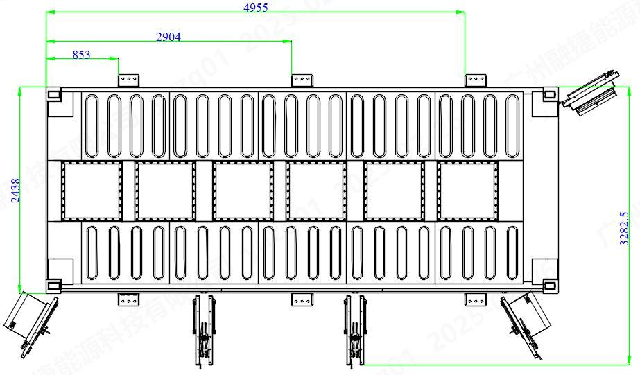
Thetotalweightofasingleenergystoragecontainersystemisabout425t,withdimensionsof6058mminlength, 2438mminwidth,and2896mminheight.Thenominalvoltageis1331.2V.Theshapeofthecontainerisshowninthe followingfigure14.
FileName ProductSpecification Page 21/22
Liftingpoint

Figure14:Schematicdiagramofcontainerlifting
Liftingpoint
4.4Fixationofcontainer
Duetothelargeweightandsizeofthecontaineritself,itgenerallydoesnotneedtobefixedHowever,containershave relativelyhighrequirementsforinstallationfoundations,andthebottomofthecontainermusthaveaconcretefoundation withsufficientstrengthandflatnessThefoundationshouldmeettherequirementsofGB50204-2015"CodeforAcceptance ofConstructionQualityofConcreteStructures"Duringcontainerinstallation,sufficientsupportareaandbearingcapacity arerequiredatthefourcornersandbottomsidebeamsofthecontainer
1Containerlifting
CompletethecontainerliftingworkaccordingtotherelevantinstructionsintheContainerLiftingandTransportation Plan,andarrangethecontainerattheplaceofusePleasepayattentiontothecontainernumberandorientationPleaserefer tothelayoutdiagramoftheenergystoragesystem

2Containersecuringrequirement
Itisrecommendedtousepebblesforcompactiontreatmentatthebottomofthecontainerfoundationtoavoid settlementofthefoundation;Thesurfaceofthefoundationshouldbeflatwithoutanyprotrusions,andthereshouldbeno wavelikefluctuationsafterplacingthecontainer
3Footmargin
FileName ProductSpecification Page 22/22