SMART SENSORS • Measure | Monitor | Configure | Predict INDUCTIVE WELD-IMMUNE & SPATTER-RESISTANT ACCESSORIES • Revolutionary protection for long life PHOTOELECTRIC FULL-METAL M12 AND M18 SERIES • Robust with excellent background suppression SAFETY LIGHT CURTAINS EXTENDED SLIM • Wireless configuration via Bluetooth® RFID WITH IO-LINK • Fast data transmission in harsh environments HIGHLIGHTS GENERALWELD-IMMUNECATALOG 2021


CONTRINEX
2 INTRODUCTION
Contrinex is a leading manufacturer of sensors for factory automation. The Swiss company, headquartered in Corminboeuf near Fribourg (CH), has a unique and innovative range of products whose features far surpass those of standard sensors. Since its foundation in 1972 by Peter Heimlicher, Dipl Ing ETH, Contrinex has grown from a one-man operation to a multinational group with over 580 employees worldwide. More than 13 subsidiaries cover the core markets in Europe, Asia, North and South America.
• World market leader for min iature sensors, sensors with long operating distances and devices for particularly demanding operating condi tions (all-metal, high-pressure and high-temperature resis tant sensors)
INTELLIGENT SENSORS FOR THE 4TH INDUSTRIAL REVOLUTION: INDUSTRY 4.0 Fit for the future with IO-Link
on the
Intelligent sensors are the fundamental building blocks of modern smart factories. They enable sensor-supported pro duction resources (machines, robots, etc.) to configure, control, manage and optimize themselves. Precise, reliable sensor data is now more essential than ever. Sensors from Contrinex, the leader in intelligent sensor technology, ensure excellent data quality. To communicate that data, all Contrinex inductive and photoelectric ASIC sensors will be equipped with IO-Link as standard. Customers use either the sensor’s binary PNP output or its intelligent IO-Link interface. Both are available in one and the same device. Another advantage is the fact that, with Contrinex sensors, there is no extra charge for IO-Link. This makes them not only quick and simple to install, but also highly economic. As the first standardized IO technology worldwide (IEC 61131-9) for communication with sensors and actuators, IO-Link is crucial to the 4th Industrial Revolution. By installing Contrinex ASIC sensors with IO-Link, users can make themselves fit for the future.
• Technology leading manu facturer of inductive and pho toelectric sensors as well as safety and RFID systems
• Represented in over 60 coun tries worldwide, headquarters in Switzerland
• 8,000 products Technology leader for sensor intelligence and industrial RFID Contrinex Headquarters, Switzerland
Detailed data sheets for these products can be found Contrinex website:
AT A GLANCE

3WWW.CONTRINEX.COM 9 Housing shape and size 9 Cable length 9 Embeddable / non-embeddable 9 Threaded / non-threaded 9 Selected technical characteristics Add your logo / non-threadedThreadedbrandor Define shape and sizeChoose cap color Contrinex has extensive experience in product custom ization and brand labelling. Over the years, a team of specialists has worked with clients to design, develop and manufacture numerous unique products that meet individual specifications. Custom solutions can range from a very simple adaptation such as a special connector or cable to a new design with special signals, technical characteristics or a customized housing. The company is also equipped to meet branding requirements for product color, packaging, labelling and logos. Production sites are available worldwide, so products can be manufactured for best availability and in quanti ties that suit the client’s requirements. Quality is assured by vigorous lab testing, pre-shipment inspections and compliance with market standards. All production sites are open to quality audits by clients.LIVECUSTOMIZATIONSENSORDATA FOR IoT INDUCTIVESENSORS 001101000101101000011010100110100010110100001101010011010001011010000110101 Continuous monitoring of process data Continuous diagnosis of sensor status Comprehensive dashboard for overview and predictive maintenance Plug & play solutions compatible with greenfield and brownfield applications Data sent to the cloud with wireless signal (no need for PLC) SMART COMMUNICATION WITH CONTRINEX SENSORSSENSORSANALYTICSCLOUD PHOTOELECTRICSENSORS RFID


9 9
9
Data monitoring
Detection counter
The sensitivity of the sensor can be adjusted remotely by changing the threshold. Alternatively, the teach function can be used to adapt the threshold to the application. Calibrated sensing ranges ensure easy sensor replacement by uploading the existing sensitivity to the replacement sensor. 9 9 LO DO
SELECTIONSEQUENCE12 Sequence selection For cross-talk immunity with through-beam sensors, up to nine different emitting sequences can be selected to pair the emitter with the receiver 9 * Functionalities may vary depending on series and sensor type
9 9
Detailed data sheets for these products can be found on the Contrinex website:4 FUNCTIONALITY* INDUCTIVE PHOTOELECTRIC RFID SMART
The output switching mode can be selected as Light-ON or Dark-ON. A single sensor type is configurable for the various needs of an application. This helps reduce the number of different sensor types required in stock. 9
Three different modes are selectable depending on the application needs: “Normal”, “Fast” and “Fine”. “Normal” mode is a good balance of speed and precision. In “Fast” mode, speed is higher and in “Fine” mode pre cision is higher. 9 9
9
Switching timer
9
LIGHT-ON/DARK-ONSELECTION
Switching state is monitored continuously. This not only monitors the signal itself, but also the state at 80% of the switching distance. One can there fore ensure that the sensor is not working at the limit of its specifications. 9 Diagnosis
Detection events are counted. By registering the number of detections, it is possible to calculate the speed or number of parts. The counter can be reset by means of a unique message. 9 Temperature
Light-ON/Dark-ON selection
SENSOR MODE Sensor mode
The timing of output switching can be configured. Depending on the needs of an application, output switching can be delayed or the duration stretched through programming. 9 9 NO/NC selection
9 9 9
The internal temperature of the sensor is measured continuously, which provides an indication about the ambient temperature in the application. Moreover, the maximum temperature measured is saved for diagnosis and preventive maintenance purposes. 9 9
9
The output switching mode can be selected as NO or NC. A single sensor type is configurable for the various needs of an application. This helps reduce the number of different sensor types required in stock. 9 9 Sensitivity and teach
The operating state of the sensor is checked. In case of open circuit, undervoltage, LC oscillator failure or installation of the wrong sensor, information is provided directly through to enable fast repair, maintenance and replacement. 9 9
9 9
5WWW.CONTRINEX.COM SMART SENSORS 6–25 INDUCTIVE SENSORS 26–117 PHOTOELECTRIC SENSORS / OPTICAL FIBERS 118–199 ULTRASONIC 200–211 SAFETY 212–259 RFID 260–297 ACCESSORIES 298–315 GLOSSARY 316–321

Detailed data sheets for these products can be found on the Contrinex website:6

HIGHLIGHTS 9 Multiple sensing modes in a single sensor: 9 Direct measurement: distance measurement, lateral position measurement (constant distance), feature detection 9 Indirect measurement: Angular measurement, lateral position measurement (inclined plane), force measure ment, vibration measurement, step counting 9 Exceptional versatility optimizes spares inventory 9 Condition-based self-monitoring minimizes maintenance costs 9 Localized D2D process logic enables sensor-based decision-making 9 Unique embedded sensor ID eliminates installation errors 9 IO-Link smart profile simplifies control-system integration 9 Full-inox devices offer increased protection in the harshest environments 9 Full-inox versions provide exceptional sensing range on aluminum, brass and copper targets 7WWW.CONTRINEX.COM

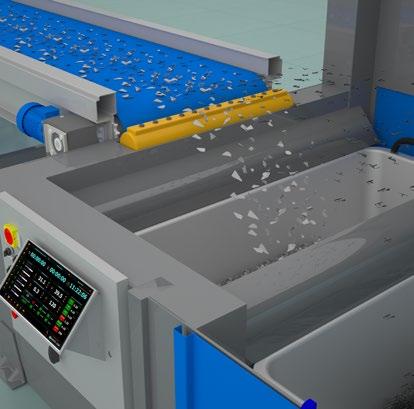
Metal recycling equipment
Spindle-cutting machine tool
Checking tool presence and position in a confined space Modern CNC machining centers cope with ranges of materials, workpieces and cutting speeds that require different tool characteristics; spindles with automatic tool-chang ing are key to optimizing throughput. If a new tool fails to engage completely, damage to the tool, the workpiece or the spindle results. Smart Sensors from Contrinex, embed ded in the body of the spindle, monitor the position of the tool during changes; any noncompliant measurements stop the process, triggering an alarm.
Robotics for pick-and-place Conveyor systems INDUSTRIES Automation, packaging, robotics, automotive, green energy, environment, logistics, machine tools, electronic assembly, food and beverage, textiles, materials handling
APPLICATION


MEASURE MONITOR CONFIGURE PREDICT Contrinex Smart Sensors, designed with the needs of OEMs and system integrators in mind, have all the answers when it comes to reducing complexity and cost. By implementing multiple sensing modes in a single sensor, Contrinex has given designers the freedom they have always dreamed about, offering exceptional versatility and simplified integration. 9 High-ResolutionMeasurement 9 Direct Device-toDevice Communication 9 User-ConfigurableOutputs 9 User-DefinedMemory 9 Embedded MaintenancePredictive-Features Q2Q1 9 Dual Channel KEY ADVANTAGES T-connector ACCESSORIES Go to pages 22 and 298 to see all the accessories Cables Mounting brackets PRODUCT OVERVIEW Housing size mm M8 M12 M18 snmm Extra Distance 0 6 0 10 0 20 Full Inox 0 6 0 10


Detailed data sheets for these products can be found on the Contrinex website:10 SMART SENSORS SMART FEATURES
DIRECT AND INDIRECT MEASUREMENT
By adopting both direct and indirect measurement techniques, Contrinex has implemented multiple sensing modes in a single Smart Sensor. Depending on the user-defined mode of operation, measurements may be output as either process data (routine, cycli cal parametric values) or event data (exceptions generated on the occurrence of a critical event). Using the Smart Sensor’s underlying capability for high-resolution distance measurement, direct measurements include axial distance (1) and lateral position (2). The sensor’s exceptional sensitivity also allows it to detect non-uniform features (for example, holes) present in a target (4). Other physical properties whose application can be translated into a displacement are also suitable for Smart Sensing. Non-contact examples include: continuous angular measurement using a cam mounted on a rotating shaft (3), lateral position measurements of larger targets using an inclined plane surface on the target (5), force measurement using a transfer element that deforms elastically (6), as well as vibration measurement (amplitude and frequency) in the axial direction (7). Step counting – either linear or rotational (8) – is another proven application for Smart Sensors. The sensitivity of these devices allows them to replace traditional encoders, which are often bulkier and more costly. Multiple sensing modes in a single sensor
1. Distance measurement 2. Lateral position measurement (constant distance) 3. Angular measurement 90° 270° 180° 0° 4. Feature detection 5. Lateral position measurement (inclined plane) 6. Force measurement 7. Vibration measurement 8. Step counting HIGH-RESOLUTIONMULTI-MODEMEASUREMENT 9
SSC SP1 SSC SP1 USER OUTPUTSCONFIGURABLE
DYNAMIC SWITCHING LOGIC
11WWW.CONTRINEX.COM SMART SENSORSVIEW SMART SENSORS DATASHEETS www.contrinex.com/collections/smart-sensors
9 Exceptional versatility optimizes spares inventory SWITCHING SIGNAL CHANNELS (SSC)
PIN ASSIGNMENT
SINGLE-POINT MODE
When specifying Contrinex Smart Sensors, designers assign their chosen switching logic to any of the available sensing modes – either as a one-time choice at the time of installation, or dynamically as the equipment operating sequence dictates. A single sensor provides all the options needed to monitor multiple parameters, with the flexibility to make real-time changes over IO-Link or via the built-in Teach function. With single-point mode selected, Smart Sensors behave as conventional two-state devices. The default logic (which may be inverted if the application requires it) sets the switching signal to “high” (SSC ON), if a threshold level or setpoint (target sensing distance, for example) has been reached. Either side of the switching point, the signal simply switches between “high” and “low” accordingly.
The Smart Sensor’s internal signals are referred to as Switching Signal Channels (SSC); the external input and output signals that result from an SSC are designated Output Switching Signals (OSS). By default, a Smart Sensor has a single-point threshold SSC enabled on Pin 4 (OSS1) of its connector, which operates in either IO-Link mode or Standard-IO (SIO) mode. On power-up, a Smart Sensor defaults to SIO mode; once the sensor is connected to an IO-Link master, a “wake-up” pulse from the master switches it to IO-Link mode. Thereafter, bidirectional communication oper ates between the master and the sensor. A second SSC may optionally be configured on Pin 2 (OSS2) of the Smart Sensor connector. If enabled, SSC2 operates solely in SIO mode and may be designated as a input or an output channel. The presence of a second IO channel gives integra tors access to powerful additional features of the Smart Sensor, including Device-to-Device communication, Teach functions and Built-in Test functions.
OSS2 OSS1
Delay Stretch Delay Stretchand One shot TIMING MODES
Two-point (hysteresis) mode showcases the Smart Sensor’s ability to respond to setpoints or threshold values that trigger a change in the SSC only when the measured value is moving in a specified direction (rising or falling). In the example shown, as the measured value falls and passes SP1, the SSC remains set to “low” (SSC OFF). Only when the measured value reaches SP2 is the SSC set to “high”. As the measured value rises again, passing SP2 has no effect on the SSC, which is only set to “low” once the measured value reaches SP1 again.
DELAY Introducing a specified delay before changing the status of the OSS in either direction prevents the sensor responding to a short-duration change in measurement value for reasons that include localized variability in the environment. Adopting a switching delay also helps prevent signal “bounce”, where the transition from one state to another may not be clearly defined.
ONE-SHOT MODE
SSC SP2 SSC SP1 SSC SP2 SSC SP1 SSC SP2 SSC SP1 WINDOW MODE SSC SP2 SSC SP1 SSC SP2 SSC SP1 SSC SP2 SSC SP1 SSC SP2 SSC SP1
Window mode allows designers to monitor a range of values, which may be defined by two discrete switching setpoints. As the example shows, the default logic sets the switching signal to “high” (SSC ON) if the measured value lies between the two setpoints. In all other cases, once the measured value moves outside the defined range, the switching signal is set to “low”.
TWO-POINT (HYSTERESIS) MODE
Modifying the timing of a change in the SSC allows designers to nullify the effect of common process events that give rise to false triggers. Such events include (i) momentary changes in measure ment value for non-process-related reasons and (ii) momentary loss of signal for known reasons.
Detailed data sheets for these products can be found on the Contrinex website:12 SMART SENSORS SMART FEATURES
Delay may optionally be combined with stretch (see below).
Smart Sensors also have the capability to generate a “one-shot” pulse on either the leading edge or the trailing edge of a change in the measurement value. One-shot pulses, also known as “differ ential up” and “differential down” may be required for secondary control functions that are implemented in a connected PLC.
STRETCH Stretching the OSS pulse ensures that the signal has a minimum duration – often desirable for control purposes or to compensate for a measurement value that varies non-linearly over time. For example, communication with a “slow” PLC may require a mini mum-duration pulse to ensure proper synchronization. Similarly, in the absence of a minimum-duration pulse, a measurement value that is not clearly defined during the transition from one state to another might otherwise give rise to multiple false triggers.
BOOLEAN “OR” Alternatively, when a Boolean “OR” function is required, a “high” signal from the secondary sensor is set to bypass the Smart Sensor signal, overwriting the SSC1 output. The Smart Sensor otherwise continues to operate normally, and consequently, its output (OSS1) is set to “high” when either sensor is triggered. Again, a two-microsecond delay is introduced.
100101011001 DIRECT COMMUNICATIONTO-DEVICEDEVICE-
BOOLEAN AND (sensor enable/disable on pin 2) BOOLEAN OR (sensor bypass on pin 2) BOOLEAN LOGIC
9 Localized D2D process logic enables sensor-based decision-making SensorSmart Photoelectricsensor
Input (OSS2/pin2) OutputSSC1 (OSS1/pin4) Sensor Output disabled= 2 ms Input (OSS2/pin2) OutputSSC1 (OSS1/pin4) SSC1bypassedsignal = 2 ms
13WWW.CONTRINEX.COM SMART SENSORSVIEW SMART SENSORS DATASHEETS www.contrinex.com/collections/smart-sensors
Designating a second SSC as an input channel allows designers to implement Boolean logic by combining an internal switching signal of the Smart Sensor (SSC1) together with that of a second two-state sensor (OSS2) operating in SIO mode. In the example shown, the Smart Sensor monitors the presence of an aluminum-foil closure on a bottle, while the secondary photoelectric sensor checks the fill level.
BOOLEAN “AND” Operating in Boolean “AND” mode, the signal from the secondary sensor is used to enable or disable the Smart Sensor, resulting in the Smart Sensor output (OSS1) being set to “high” only when both sensors are triggered. The output signal on OSS1 is delayed by two microseconds.

SSC SP2 SSC SP1 SSC SP2 SSC SP1 SSC SP2 SSC SP1 SSC SP1 SSC SP2 Factor y Default Step 1 Step 2 Step 3
Detailed data sheets for these products can be found on the Contrinex website:14 SMART SENSORS SMART FEATURES
EXTERNAL TEACH (high/low signal on pin 2) TEACH FUNCTION Teaching the sensor externally to recognize one or more setpoints is another D2D function. Smart Sensors are supplied with default (factory-set) values for SP1 and SP2; during commissioning, engineers use either a locally connected teach device or a remote PLC to communicate with the Smart Sensor via OSS2. Positioning the target at the first setpoint and triggering the teach pulse sets SP1 on the rising edge of the pulse. Repositioning the target to the second setpoint and removing the teach pulse then sets SP2 on the falling edge of the pulse.
SSC SP1 SSC SP1SSC SP1 BOOLEAN XOR (BITE function on pin 2)BUILT-IN TEST (BITE) FUNCTION
Time TEACH (pin 2) Set SP1 on pin 2 rising edge Set SP2 on pin 2 falling edge
The SSC2 input channel serves an additional purpose when a self-test function is required. A BITE signal on SSC2 from a con nected PLC or microcontroller is used (i) to determine whether the Smart Sensor is functioning correctly and (ii) to establish the presence or absence of a target. A BITE handshake pulse returned by the sensor confirms its working state, while the polarity of the pulse indicates the pres ence or absence of a target. Failure by the sensor to return a handshake pulse signifies a defective device.
BITE (pin 2) OUTPUT (pin 4) Target detection Sensor failure Time = 2 ms = 2 ms No answer from sensor
9 IO-Link smart profile simplifies control-system integration
Should a remote sensor identify an out-of-range parameter that requires immediate intervention, (for example, overheating), an event-based output signal is generated to notify the central control system – in the example shown, a PLC – that a system-wide shutdown is essential. In this instance, the IO-Link output (OSS1) may not respond quickly enough to prevent the problem escalating. Using the SIO output on OSS2, the sensor delivers a high-speed notification directly to the PLC, bypassing the IO-Link channel and initiating the shut-down sequence immediately. The Smart Sensor’s dual-channel capability ensures that further, costly damage is avoided and that subsequent process down-time is minimized.
15WWW.CONTRINEX.COM SMART SENSORSVIEW SMART SENSORS DATASHEETS www.contrinex.com/collections/smart-sensors
LOCALIZED HIGH-SPEED CONTROL Enabling OSS2 on Pin 2 of the Smart Sensor connector gives system integrators access to localized high-speed control options; as already noted, OSS2 operates solely in SIO mode and may be designated as a input or an output channel. In addition to D2D communication, two specific advantages stand out.
OS S2/SIO REMOTEOUTPUTSENSINGTASKS DECENTRALIZEDSENSINGTASKLOCALINHIBITCONTROLOS S2/S SC1 OS S2/SIO INPUT OS S2/S SC1 MASTERPLC Power
DECENTRALIZED CONTROL
REPORTING TIME-CRITICAL EVENTS
DUAL CHANNEL DUAL CHANNEL
9 High-speed sensor-based decision-making using SIO
Smart Sensors are also ideally suited to non-criti cal, decentralized process tasks under local control. In the example shown, a local SIO input signal on OSS2 enables or inhibits the operation of the sensor without the need to route the command via the PLC. This configuration consumes little or no system-wide resource, requiring only a confirmatory IO-Link signal on OSS1 to update the sensor status in due course. With OSS2 signal alternatively configured in output mode, the Smart Sensor may, for example, control the operation of a local sub-system, again without the need to route the command via the PLC. Using the signal to switch a simple two-state device allows the sensor to control the operation of any associated non-intelligent equipment, for example an actuator or an electrical circuit. TIME-CRITICAL EVENT
cableFieldbus REPORTING OF
CYCLICAL AND EVENT-BASED REPORTING
costs 9
MAINTENANCEPREDICTIVEFEATURES 9
FEATURESSAVINGTIME BY DESIGN
In a fast-moving process-manufacturing environment, down-time is a major cost factor. While some interrup tions to production are inevitable, minimizing lost time is a priority, and Smart Sensors offer big benefits here, saving time by design.
THRESHOLD EXCEPTIONS
sensor replacement Distance SSC
The sensor’s records cumulative data for distance, cycle count and temperature, with alarm thresholds set for each. Cumulative cycle-count limits for the expected life of the equipment being monitored are programmed into the sensor, and a threshold alarm is triggered when the set value is exceeded, typically via IO-Link, although a high-speed SIO output may be used instead. In the case of distance and temperature, a single, ultimate limit for each parameter is set, and any measurement that exceeds either limit is sufficient to trigger an alarm; in this instance, a high-speed SIO signal is almost certainly the preferred option. Cumulative temperature measurements may also trigger a parametric-shift alarm, as explained below.
The Smart Sensor’s predictive-maintenance capabilities rely on its ability to collect both process data and event data, as well as making use of its on-board cumula tive-data stores. Not only can maintenance engineers monitor long-term equipment behavior, they also have confidence in the sensor’s ability to flag any one-off threshold exceptions that require attention.
Detailed data sheets for these products can be found on the Contrinex website:16 SMART SENSORS SMART
Once initial commissioning is completed, each sensor’s configuration is stored automatically on the local IO-Link Master; this allows plug-and-play replacement of sensors should the need arise, without any loss of functionality and without any need for recalibration. Down-time and the associated maintenance cost is kept to a minimum. Condition-based self-monitoring minimizes maintenance Plug-and-play ALRSP1 SSCALRSP1 Counter Temperature
PLUG-AND-PLAY REPLACEMENT
www.contrinex.com/collections/smart-sensors
TAG NAME SIZE [BYTE] EXAMPLES
Stored measurements from a prolonged period of operation provide maintenance engineers with a pattern of data over time; typically, the data will form a normal dis tribution centered around the expected mean value for the parameter in question.
USER-DEFINEDMEMORY
Application-Specific Tag 32 “end of motion”, “piston #1”, “fwd stroke”
Examples include, but are not limited to, equipment temperature (as above) and amplitude of vibrations. The comprehensive data patterns allow engineers to recognize any parametric shifts that occur over time. These may include a shift in the mean value, where, for example, a sustained rise in temperature occurs at a level that isn’t high enough to trigger a threshold alarm. Alternatively, an increase in the standard deviation of measurements, for example, when vibrations become unstable, may result. In either case, a parametric-shift alarm is triggered, allowing engineers to take remedial action.
The advent of the Internet of Things (IoT) has changed the way engineers look at integrated pro cesses in manufacturing and logistics. No longer do system designers consider production lines and distribution centers to be made up of discrete com ponents – conveyors, actuators, motors, sensors, controllers and other similar hardware – but instead they consider more complex Functional Units. Working with a functional unit, the need to iden tify individual components remains as important as ever; installing the wrong sensor could have far-reaching consequences. Contrinex Smart Sen sors make it simple to get the right device in the right place, eliminating errors and avoiding costly interventions. CUSTOMIZED SENSOR-DATA TAGS Within each Smart Sensor, three read-write data tags are reserved for user-defined information. Designated the function tag, the location tag and the application-specific tag, respectively, they link individual sensors to specific applications or tasks, allowing process engineers to locate a discrete device quickly and easily. This simplifies installation and maintenance when more than one sensor is used in a single functional unit.
Function Tag 32 “Drive”, “Feed”, “Forward” Location Tag 32 “AQ3.1”, “S45-2”
17WWW.CONTRINEX.COM SMART SENSORSVIEW SMART SENSORS DATASHEETS
PARAMETRIC SHIFT
9 Unique embedded sensor ID eliminates installation errors
EMBRACING THE INTERNET OF THINGS
Rugged, multi-mode Smart Sensors from Contrinex, embedded in each cylinder, identify adverse trends in the deceleration profile, providing a cost-effective, unobtrusive fit-and-forget solution.
Monitor temperature, vibration and process cycle count for maintenance purposes Local storage of sensor configurations, allowing plug-and-play replacement when needed
Industrial equipment designers continually seek ways to reduce cycle times without compromising safety or increasing cost, and require a monitoring capability for pneumatic cylinders that identifies deviations from the optimal deceleration profile without increas ing complexity or cost.
SMART TASKS
MULTI-MODE MEASUREMENT OF PISTON DISPLACEMENT AND SPEED
9 Dual-channel capability enables a local alarm to be triggered by an event-based exception, avoiding a plantwide shut-down
9 Sensor configurations are stored locally, allowing plugand-play replacement of sensors when needed
DUAL CHANNEL High-speed communication with central control system for time-critical events
9 Embeddable inductive Smart Sensors offer multiple sensing modes in a single device, eliminating increased complexity and cost
CUSTOMER BENEFITS
High-resolution measurement of lateral piston displacement
Generation of velocity gradient using on-board cumulative data store
PNEUMATICS
SMART TASKS
9 One-shot timer feature allows process engineers to identify deviations from the optimal deceleration profile, minimizing maintenance expense
9 Industry-standard IO-Link connectivity provides a single interface to the machine control system
Repeated high-speed displacement measurement at timed intervals
Detailed data sheets for these products can be found on the Contrinex website:18 SMART SENSORS
9 Proven technology ensures highly reliable fit-and-forget operation with no manual intervention
9 Cumulative operating data for predictive maintenance, including temperature and operating-cycle count, is recorded in on-board data storage


19WWW.CONTRINEX.COM SMART SENSORSVIEW SMART SENSORS DATASHEETS
9 Compact embeddable M12 sensors fit unobtrusively and easily into off-the-shelf linear guide rails
DUAL
Automation engineers designing high-speed assembly equipment with multiple linear transfers between workstations need to maximize speed and accuracy while keeping cost down. They require a single-sensor positional-control solution that delivers a high-speed approach to the critical areas and a slower, high-precision final positioning. An inductive Smart Sensor from Contrinex with IO-Link connectivity and multiple user-configurable outputs performs both the required tasks in a highly cost-effective manner.
9 Rugged inductive Smart Sensors ensure accurate positioning of linear stages without compromising operational speed
9 Sensor configurations are stored locally, allowing plugand-play replacement of sensors when needed
www.contrinex.com/collections/smart-sensors
9 Proven technology ensures highly reliable fit-and-forget operation with no manual intervention BENEFITS CHANNEL Reliable position sensing on high-speed approach High-accuracy lateral position measurement during final stage positioning Sensor configuration is backed-up automatically on the local IO-Link Master IO-Link smart profile simplifies controlsystem integration Unique embedded sensor ID eliminates installation errors User-configured setpoints ensure precise window-mode positioning SMART TASKS
CUSTOMER
9 Single-sensor positional-control system is non-complex and highly affordable
LINEAR GUIDE PERFECT LOCATION AND POSITIONING OF LINEAR STAGE
9 Industry-standard IO-Link connectivity provides a single interface to the machine control system

Detailed data sheets for these products can be found on the Contrinex website:20 SMART SENSORS SMART TASKS SPINDLE CHECKING TOOL PRESENCE AND POSITION IN A CONFINED SPACE Modern CNC machining centers cope with ranges of materials, workpieces and cutting speeds that require different tool characteristics; spindles with automatic tool-changing are key to optimizing throughput. If a new tool fails to engage completely, damage to the tool, the workpiece or the spindle results. Smart Sensors from Contrinex, embedded in the body of the spindle, monitor the position of the tool during changes; any noncompliant measurements stop the process, triggering an alarm. 100101011001 Precision real-time measurement of drawbar position Threshold alarms identify overtemperature and end of service life Sensor configuration is backed-up automatically on the local IO-Link Master Self-test function guards against sensor failure User-configured setpoints ensure accurate end-of-travel position sensing DUAL CHANNEL High-speed notification of timecritical events 9 Embeddable inductive Smart Sensor monitors drawbar position, detecting incomplete tool engagement and inhibiting further motion before damage occurs 9 Single-sensor positional-control system is non-complex and highly affordable 9 Embeddable M12 sensor fits snugly in the limited space available 9 Industry-standard IO-Link connectivity provides a single interface to the machine control system 9 Cumulative operating data for predictive maintenance, including temperature and operating-cycle count, is recorded in on-board data storage 9 Sensor configurations are stored locally, allowing plugand-play replacement of sensors when needed 9 Proven technology ensures highly reliable fit-and-forget operation with no manual intervention CUSTOMER BENEFITS SMART TASKS


CUSTOMER
RECYCLING RELIABLE DETECTION OF DIFFERENT METALLIC MATERIALS
9 Cumulative operating data for predictive maintenance, including temperature and operating-cycle count, is recorded in on-board data storage
9 Embeddable inductive Smart Sensors detect ferrous and non-ferrous metal and trigger separation accurately and reliably 9 A single array of sensors provides continuous detection across the full width of a conveyor
9 Sensor configurations are stored locally, allowing plugand-play replacement of sensors when needed
9 Proven technology ensures highly reliable fit-and-forget operation with no manual intervention BENEFITS
Threshold alarms identify overtemperature and end of service life Sensor configuration is backed-up automatically on the local IO-Link Master TASKS
SMART
www.contrinex.com/collections/smart-sensors
The global recycling industry continually seeks to reduce the cost of sorting and separating mixed-metal scrap. With the introduction of induction sorting, designers require sensors that operate accurately and at high speed to identify and separate fast-moving streams of ferrous and non-ferrous material in a single pass. Rugged inductive Smart Sensors from Contrinex, embedded immediately below the delivery belt, provide continuous high-speed detection across the full width of a conveyor
9 Smart Sensors are easily able to identify material on fast-moving conveyors 9 Industry-standard IO-Link connectivity provides a single interface to the machine control system
Unique embedded sensor ID eliminates installation error DUAL CHANNEL High-speed localized communication with air-knife actuators
21WWW.CONTRINEX.COM SMART SENSORSVIEW SMART SENSORS DATASHEETS
Multi-mode target recognition at constant target distance Cumulative cycle/target counting in each of two modes


We made these pages with care, but we decline liability for any errors or omissions.22 SMART SENSORS PRODUCTOPERATINGOVERVIEWDISTANCE(mm)HOUSINGSIZE(mm) HOUSINGLENGTH(mm) MATERIALHOUSING Supply Voltage range 15 30 VDC Output PNP NO COMMON FEATURES A Group A: M8 3-pin Sub-group: Field attachable connectors Sub-group: Distribution boxes B Group B: M8 4-pin C Group C: M12 4-pin Sub-group: Field attachable connectors Sub-group: Distribution boxes D Group D: M12 AC/DC 3-pin E Group E: Universal mounting brackets Sub-group: Mechanical stops F Group F: Photoelectric mounting brackets G Group G: Photoelectric reflectors H Group H: Sensor tester Go to page 298 for details ACCESSORIES INOXFULLDISTANCEEXTRAFAMILYSERIES500SERIES700*T-CONNECTOROUTPUT Reference key on page 24 IDW[x]-M[x]M[x]-NMS-A0 Mounting [E] Embeddable [N] Non-embeddable Housing size [8] Diameter 8 mm [12] Diameter 12 mm [18] Diameter 18 mm Front material [M] Metal [P] Plastic M8 66 Chrome-platedbrass M8 66 Chrome-platedbrass M12 60 Chrome-platedbrass M12 60 Chrome-platedbrass M18 63.5 Chrome-platedbrass M18 63.5 Chrome-platedbrass CONNECTION 1 SIZE PINS 1 2 3 M12 socket 5 M12 60 Stainless steel V2A M18 63.5 Stainless steel V2A *Available from Q1/2022


23WWW.CONTRINEX.COM SMART SENSORS CONNECTOR FREQUENCYSAMPLING(Hz) MOUNTING TEMPERATUREAMBIENT DEGREE PROTECTIONOF PART REFERENCE (SEEACCESSORIESPAGE22)EMB. NON-EMB. Detailed data sheets for these products can be found on the Contrinex website: VIEW SMART SENSORS DATASHEETS www.contrinex.com/collections/smart-sensors 1,000 Embed. −25…+70°C IP67 IDWE-M8MP-NMS-A0 CEH 1,000 Non-embed. −25…+70°C IP67 IDWN-M8MP-NMS-A0 CEH 1,000 Embed. −25…+70°C IP67 IDWE-M12MP-NMS-A0 CEH 1,000 Non-embed. −25…+70°C IP67 IDWN-M12MP-NMS-A0 CEH 1,000 Embed. −25…+70°C IP67 IDWE-M18MP-NMS-A0 CEH 1,000 Non-embed. −25…+70°C IP67 IDWN-M18MP-NMS-A0 CEH CONNECTION 2 CONNECTION 3 PART REFERENCE SIZE PINS SIZE PINS M12 plug 5 M12 socket 5 V12-5TPD-000-NN1 1,000 Embed. −25…+70°C IP68 / IP69K IDWE-M12MM-NMS-A0* CEH 1,000 Embed. −25…+70°C IP68 / IP69K IDWE-M18MM-NMS-A0* CEH

Detailed data sheets for these products can be found on the Contrinex website:24 SMART SENSORS REFERENCE IDWE-M8MP-NMS-A0KEY(-XXX) Rectangular C Cylindrical, threaded M Cylindrical, high-pressure resistant P Digital measuring and switching ID Analog measuring IA Adjustable switching IS Metal M Plastic PMetal M Plastic P No local user interface N SPECIAL ADJUSTMENTEXECUTIONS HOUSING MATERIAL OUTPUT 1 (PIN 4) OUTPUT 2 (PIN 2) SENSING FACE MATERIAL MOUNTING / EMISSION TYPE HOUSING TYPE SMART SENSOR PLATFORM HOUSING SIZE Embeddable E Non-embeddable N Red LED R Switching Outputs PNP NO 0 Analog measuring Linear voltage output 0–5 V 1 Linear voltage output 0–10 V 2 Linear current output 1–5 mA 3 Linear current output 4–20 mA 4 Switching Outputs PNP NO / IO-Link A Analog measuring PNP NO / IO-Link A Linear voltage output 0–5 V 1 Linear voltage output 0–10 V 2 Cable K Connector S CONNECTION Standard M Short S DETECTION RANGE Inductive W Photoelectric distance D Photoelectric background suppression H Photoelectric through beam L Photoelectric reflex R Photoelectric diffuse T SENSING CylindricalPRINCIPLE ∅ 8 mm 8 ∅ 12 mm 12 ∅ 18 mm 18 Rectangular 2# mm × 3# mm 23
25WWW.CONTRINEX.COM REFERENCE KEY VIEW SMART SENSORS DATASHEETS www.contrinex.com/collections/smart-sensors

Detailed data sheets for these products can be found on the Contrinex website:26

27SENSORSINDUCTIVEWWW.CONTRINEX.COMHIGHLIGHTS 9 Smallest self-contained miniature inductive sensors with on the market 9 Practically indestructible Full Inox sensors for extreme conditions 9 Weld-Immune Full Inox sensors, M8, M12, M18, M30, C23 9 Full Inox sensors with Factor 1 on steel and aluminum 9 Sensors with 4× standard operating distance 9 Outstandingly durable sensors for high cyclic pressures (peak: 1000 bar / 14510 psi) 9 Highly accurate analog output sensors for distance control 9 Sensors to withstand high temperatures (up to 230°C / 446°F) 9 Ecolab-approved sensors NEW 9 Full Inox Chip-Immune sensors for machining environments 9 Full Inox Maritime DNV-GL approved sensors
Detailed data sheets for these products can be found on the Contrinex website:28 INDUCTIVE SENSORS PROGRAM OVERVIEW HOUSING SIZE (mm) OPERATING DISTANCE (mm) BASIC MINIATURE EXTREME ANALOGOUTPUTFAMILYCLASSICS–SERIES600EXTRADISTANCE–SERIES500FULLINOX–SERIES700 ∅ 3 p. 50 51 M4 p. 50 51 ∅ 4 p. 50 51 M5 p. 50 51 C5 p. 52 53 ∅ 6.5 p. 38 41 M8 p. 40 43 C8 p. 42 43 MM1012 p. 42 43 M18 p. 42 45 M30 p. 44 45 40M50×40 p. 44 45 ∅ 4 p. 50 51 M5 / P5 p. 50 51 ∅ 6.5 p. 36 37 M8 / P8 p. 36 37 p. 62 63 C8 p. 36 37 p. 62 63 M12 / P12 p. 36 37 p. 62 63 M18 p. 36 39 p. 62 63 M30 p. 38 39 p. 64 65 M14 / P20 ∅ 4 p. 52 53 M5 p. 52 53 M8 p. 46 47 p. 56 57 M12 / P12 p. 46 47 p. 56 57 M18 p. 46 47 p. 56 57 M30 p. 46 47 p. 56 59 C23 p. 58 59

VIEW DATASHEETSINDUCTIVE www.contrinex.com/collections/inductive-sensors PROGRAM OVERVIEW 29WWW.CONTRINEX.COM 2-WIRE EXTRA/HIGHPRESSUREUPTO1,000BARPEAK EXTRA TEMP. HIGH TEMP. −40 TO +230°C IMMUNEWELD- IMMUNECHIP- DOUBLE-SHEET MARITIME WASHDOWN p. 68 69 p. 76 77 p. 68 69 p. 68 69 p. 76 77 p. 68 69 p. 86 87 p. 68 69 p. 68 69 p. 68 69 p. 86 87, p. 90 91 p. 98 99 p. 110 111 p. 68 71 p. 86 87, p. 90 91 p. 98 99 p. 114 115 p. 70 73 p. 86 87, p. 90 91 p. 98 99 p. 72 73 p. 90 91 p. 90 91 p. 80 81 p. 76 77 p. 76 77, p. 80 81 p. 80 81 p. 80 81 p. 96 97 p. 82 83 p. 96 97 p. 104 105 p. 110 111 p. 114 115 p. 96 97 p. 104 105 p. 110 111 p. 114 115 p. 96 97 p. 104 105 p. 106 107 p. 110 111 p. 114 115 p. 96 97 p. 110 111
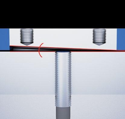
EXTRA DISTANCE FAMILY Increased stability for exceptionally long oper ating distance The Extra Distance family is based on the Condist® oscillator developed by Contrinex. Sensors benefit from up to 4× the standard operating distance, keeping them out of harm’s way in rugged, indus trial environments. Sensor lifetime is therefore increased.
Like Classics family sensors, these also generate a high-frequency magnetic field that emerges at the sensing face (Fig. 2). Again, the resulting effect is that any metallic object entering the field absorbs energy from it. However, the oscillator and the subsequent signal evaluation circuit are completely different, with the objective of achieving a significantly better stability with respect to environmental influences, in particular temperature. The most important contri bution to this comes from the Contrinex Condist® Improvedoscillator. stability permits the switch point to be further away, leading to long operating distances on ferromagnetic metals (Fig. 3). Sensors with this technology also react particularly well to narrow targets, e.g. small screws, wires and foils. Apart from the Condist® oscillator, all other assem blies are equivalent to the Classics family. Material Fig. 3: Extra Distance family sensors have a longer operating distance, due to Condist® oscillator technology sensorstandard sensorCondist®
Fig. 2: Contrinex’s Condist® inductive sensor technology, as used in the Extra Distance family output amplifier HF magnetic field sensing face signalcoil shaping Condist® ferriteoutput Condistcore®oscillator
Conventional technology, engineered by Contrinex
Fig. 1: Conventional inductive sensor technology, as used in the Classics family output amplifier HF magnetic field sensing face
Contrinex inductive devices work according to one of three different technologies. All involve the generation of an alternating magnetic field that emerges at the sensing face. The presence of a conductive, generally metallic, object influences this field in a way that can be detected and evaluated by built-in electronics. All Contrinex ASIC sensors are IO-Link enabled in PNP NO versions.
Ferromagnetic metals (steel, nickel, cobalt) absorb the most energy. The achievable operating dis tances are therefore greatest with these metals. Non-ferromagnetic metals, such as aluminum, absorb less energy. As a result, operating distances are lower (approx. 25 … 45% of those on steel).
The Classics family uses conventional induc tive sensor technology, but with the benefit of a Contrinex ASIC (application specific integrated cir cuit). ASIC technology ensures reliability, stability and ease of commissioning, due to low variation. Sensors in this family achieve operating distances up to 2× the industry standard. All ASIC sensors in the Classics family are IO-Link enabled in PNP NO versions. Classics sensors have a conventional oscillator and coil generating a high-frequency magnetic field that emerges at the sensing face. Any metal lic object found in this field absorbs some of the energy, which is in turn detected and evaluated by built-in electronics (Fig. 1).
The Classics technology family (series 600) includes devices from the ranges Basic, Minia ture, Extra Pressure, Extra Temperature, High Temperature, Washdown and 2-Wire.
TECHNOLOGY
FAMILIESTECHNOLOGYCLASSICSFAMILY
ferriteoutputsignaloscillatorcoilshapingcore
Detailed data sheets for these products can be found on the Contrinex website:30 INTRODUCTION


The Extra Distance technology family includes devices from the Basic, Miniature, Extra Pressure, High Pressure and Analog Output ranges. This technology is used in series 500 devices.
sensingoutput face signalcoil
The Full Inox family is based on Contrinex’s Condet® technology. These one-piece stainless steel sensors are not only the most durable on the market, they also offer long operating distances on any conductive metal. Full Inox sensors also function according to induc tive technology. However, the coil which generates Fig. 5: Evolution of main signals Iu Ui Fig. 6 t Fig. 6 (detail fig. 5): Effect of a target on the measured signal without targetwithtarget t U the magnetic field is not part of the oscillator (Fig. 4). Instead, the field is generated by peri odic, short transmitter current pulses, which flow through the coil (Fig. 5). This field induces a voltage in the target which, in turn, generates a current flow in it. When the transmitter current pulse is switched off, the current in the object dies away, causing a voltage to be induced in the transmitting coil (Fig. 6). This voltage generates the signal required, and is in principle independent of the field’s energy loss. Therein lies the fundamental advantage of this technology, since the field energy losses, which are evaluated in conventional sensors, are subject to a number of undesirable environmental and material influences. Condet® technology allows the sen sor, including its face, to be fully encapsulated in a protective, stainless steel housing, with the added security of long operating distances. The coupling between the target and the coil is rather like a transformer, and is hence temper ature independent and only slightly influenced by the target’s material. Operating distances are therefore identical on steel and aluminum. Only metals which are non-ferromagnetic and also have poor electrical conductivity give a reduced usable Thesignal.
FULL INOX FAMILY All-round stainless steel protection – practically indestructible
31WWW.CONTRINEX.COM
shaping filter ferriteswitchcore dependencies and other properties are also the same as for Classics family sensors. Special attention has been paid to meet the rele vant standards as much as possible, so that easy interchangeability with conventional devices is guaranteed. Great emphasis has been placed on very good EMC resistance and on perfect sealing against liquid penetration.
Full Inox family includes devices from the Basic, Miniature, Extreme, High Pressure, Wash down, Weld-Immune, Chip-Immune, Maritime and Double-Sheet ranges.
Fig. 4: Full Inox family sensors use Condet® pulse generator technology instead of an oscillator generatorpulse output amplifier alternating magnetic field


Continuous analog output for precision control Pressure resistant up to 200 bar
PRESSUREEXTRA
Engineers needing a reliable, repeatable, highly accurate means of measuring the position of a target object should look no further than Contrinex Analog Output inductive sensors. This range of sensors has been developed on the platform of Extra Distance (Fig. 2) technology for excellent temperature stability, repeat accuracy, and the best long-range sensing capability on the market. With a measurement range of zero to 40 mm and detection accuracy on the micron scale, the Analog Output sensor range is ideally suited for measuring linear, angular and rotational position (Fig. 7).
Contrinex Basic range induc tive sensors have a worldwide and well-deserved reputation for uncompromising accu racy and exceptional reliabil ity. With best-in-class sensing distances between 1.5 mm and 40 mm, the Basic range offers fit-and-forget operation, delivering world-class perfor mance and a highly attractive total cost of ownership. Size is often a critical con straint when selecting sensors for position- or presence-sens ing. The Contrinex Miniature range, which includes the smallest self-contained induc tive sensors on the market, meets this constraint without compromising on functionality.
OUTPUTANALOG
2-WIRE Easy installation and high switching frequency Fig. 7 aluminum steel
The 2-Wire range of DC, AC/ DC and NAMUR sensors is constructed on the Classics (Fig. 1) technology platform and includes sizes from ∅ 3 to M30, plus a 5 × 5 mm square-section type. Devices are available for embeddable or non-embeddable mounting and connection is by means of cable or connector. With a sensing range up to 15 mm, Contrinex 2-Wire sensors ensure optimal equipment utilization. Dependable, accurate pres ence- and position-sensing at pressures up to 200 bar requires world-class per formance and build quality. The Extra Pressure range of pressure-resistant inductive sensors delivers exactly that, operating continuously in permanently pressurized con ditions. This makes the range especially suitable for offshore installations, the chemical industry, motor lubrication sys tems and atomic fuel element monitoring. A stain less-steel housing with bonded ceramic or brazed sapphire sensing face and protection class IP68 guarantees robustness and exceptional reliability in miniature packages sized from ∅ 3 to ∅ 6.5 For reliable, accurate sensing in the most demanding pneu matic and hydraulic appli cations, Contrinex offers a unique range of High Pressure sensors with permanent oper ating pressures of 100 500 bar and peak pressures up to 1000 bar Suitable for operating tem peratures up to 100°C and resistant to more than one million pressure cycles, their IP68 and IP69K protection and oil impermeability make them the robust, reliable choice for the hydraulic industry. Fit-and-forget operation virtually eliminates sensor replacement costs. Exceptional performance and world-class quality are assured in sizes from M5 to M18. Only the toughest sensors survive the most extreme environments, and Extreme range inductive sensors from the Full Inox family are ideally equipped for the job. Thanks to one-piece stainless-steel (V2A/AISI 303) construction and a hermetically sealed cable entry, Extreme sensors are corrosion-resistant, imper vious to oil, and pressure-resistant to 100 bar. Rug ged, reliable and highly accurate, the Extreme range is at home in the most challenging circumstances.
Detailed data sheets for these products can be found on the Contrinex website:32 INDUCTIVE SENSORS
MINIATURE Full functionality, smallest size EXTREME Extreme durability in harsh environments BASIC First choice in all environments
PRESSUREHIGH Resistant to pressure and dynamic stress up to 500 bar


SHEETDOUBLEDetection of double-sheets in metalworking Washdown inductive sensors are certified to operate contin uously and reliably in the harsh conditions of the food, bever age and pharmaceutical indus tries, ensuring uninterrupted production. Rated to IP68 and IP69K, they are pressure resistant up to 80 bar, food safe and corrosion resistant; additionally Full Inox – Series 700 are Ecolab certified. Washdown sensors are avail able in conventional Classics (Fig. 1) technology, size M12, or Full Inox (Fig. 4) technology, sizes M12, M18 and M30. Full Inox types have a totally impervious one-piece housing in stainless-steel (V4A / AISI 316L), including the sensing face. They are therefore highly resistant to the corrosive chemicals used for clean-in-place or wash-down processes.
Contrinex Weld-Immune induc tive sensors are ideal for the harshest welding environments thanks to the revolutionary triple protection. The range includes anti-spatter coated, weld-field immune and impact resistant sensors. For extensive protec tion, we recommend using our accessories such as our coated mounting brackets, spatter-re sistant cables and protective tubes. Benefits include reduced cleaning and main tenance costs, longer sensor service-life and thus increased machine availability.
For the harshest machining environments MARITIME DNV approved for ships, ports and offshore
Even when covered with chips of steel, stainless steel, alu minum, brass, copper or tita nium, Chip-Immune inductive sensors from the Full Inox technology family will reliably detect targets made of these metals. The sensors achieve this with a slightly modified form of Condet® technology. In a one-piece stainless steel housing with IP68/IP69K protection rating and a wide operating temperature range from −25 to +85°C (−13 to +185°F), they are particularly suitable for use in the harsh environ ments of the machining industry. Depending on sensor diameter (M12, M18 or M30), operating distances of 3, 5 or 12 mm are available.
WASHDOWN Ecolab approved for harshest cleaning processes
The Maritime range of embed dable inductive sensors, cer tified by DNV, offers unrivaled performance features based on Full Inox technology (Fig. 4). With a one-piece housing in V4A/AISI 316L stainless steel and an enclo sure rating of IP68/IP69K, they are not only impervious, but also corrosion-proof and resis tant to salt water. Their EMC protection also meets specific maritime requirements, partic ularly with regard to power supply variations and low frequency immunity. They offer the longest service life of any inductive sensor on the market, even in the harshest marine environments.
33WWW.CONTRINEX.COM
TEMPERATUREEXTRA Temperature resistant up to 120°C CHIP-IMMUNE
Contrinex High Temperature inductive sensors are designed for continuous operation at temperatures from 0°C up to 180°C (up to 230°C with remote electronics). The range is ideal for the harshest environments, including automotive paint shops, metal-treatment plants and glass manufacturing.
Temperature resistant up to 180°C (230°C with external amplifier) Inductive sensors from the Extra Temperature range offer the ideal solution for positionand presence-sensing appli cations at temperatures from as low as minus 40°C up to 120°C. Industrial processes often generate heat, resulting in temperatures that would dam age a standard sensor, but the stainless-steel construction and robust electronics of Contrinex Extra Temperature sensors ensure reliable, accurate operation and minimal downtime, even in the most demanding environments.
TEMPERATUREHIGH
WELD-IMMUNE Immune to magnetic fields and resistant to weld spatter For double-sheet detection, sensors from the Full Inox (Fig. 4) family are used. Its inductive technology enables discrimination between one and two conductive metal sheets of a defined thick ness, achieving sensitivity of 0.8–1.2 mm per sheet. This discrimination aids in the prevention of double feeds into blanking and forming processes which ultimately saves damage to tooling. The one-piece, stainless-steel construction of these sensors makes them the most durable on the market. They withstand the impacts that are a common hazard in double-sheet detection applications close to moving sheet metal, ensuring minimal down-time.


Extra Distance inductive sensors detect presence of metal washers in plastic assemblies A plastics manufacturer tests batches of control knobs for in-car audio systems before shipment to automo tive assembly plants; each knob contains a small metal washer that occasionally becomes dislodged. A cus tom-built testing machine tests a tray of 70 knobs in a single cycle; long-distance inductive sensors, positioned directly below the knobs, confirm the presence of a washer in each assembly.
Textile spinning machine automation Wind turbine speed monitoring Position detection on crane Presence sensing in automotive factory INDUSTRIES Automotive production and supply, machine tool, energy, packaging, logistics, materials handling, textile, assembly, automation
APPLICATION


INDUCTIVE SENSORSBASICFIRSTCHOICE IN ALL ENVIRONMENTS Contrinex Basic inductive sensors have a worldwide and well-deserved reputation for uncompromising accuracy and exceptional reliability. With best-in-class sensing distances between 1.5 mm and 40 mm, the Contrinex Basic range offers fit-andforget operation, delivering worldclass performance and a highly attractive total cost of ownership. PRODUCT OVERVIEW Housing size mm ∅ 6.5 M8 C8 M12 M18 M30 C44 snmm Extra Distance 3 3 6 3 6 10 12 20 22 40 Classics 1.5 2 1.5 4 1.5 2 2 8 5 12 10 25 15 40 Full Inox 2 3 5 10 ACCESSORIES Go to page 298 to see all the accessories KEY ADVANTAGES Classics, Extra Distance and Full Inox 9 High quality ASIC sensors 9 9 Exceptional price/performance ratio 9 Excellent accuracy 9 Outstanding temperature compensation 9 Vibration and shock resistant 9 Long operating distance Full Inox 9 Extremely robust one-piece stainless-steel housing 9 Corrosion resistant 9 IP68 and IP69K, water resistant 9 Pressure resistant up to 80 bar (1,160 psi) Cables Mounting brackets


36 FAMILYEXTRADISTANCE–SERIES500 OPERATING DISTANCE (mm) HOUSINGSIZE(mm) HOUSINGLENGTH(mm) MATERIALHOUSING Supply Voltage range 10 30 VDC Output PNP NO* * Other types available: PNP NC, NPN NC ** Pigtail versions available COMMON INDUCTIVEFEATURES SENSORS BASIC CABLES Cable lengths available: 2 m, 5 m, 10 m other customised lengths possible A Group A: M8 3-pin Sub-group: Field attachable connectors Sub-group: Distribution boxes B Group B: M8 4-pin C Group C: M12 4-pin Sub-group: Field attachable connectors Sub-group: Distribution boxes D Group D: M12 AC/DC 3-pin E Group E: Universal mounting brackets Sub-group: Mechanical stops F Group F: Photoelectric mounting brackets G Group G: Photoelectric reflectors H Group H: Sensor tester Go to page 298 for details OUTPUTACCESSORIES [3] PNP NO [4] PNP NC DW-A[x]-50[x] Connection [D] Cable [S] Connector [V] Pigtail Output [1] NPN NO [2] NPN NC Reference key on page 116 We made these pages with care, but we decline liability for any errors or omissions. ∅ 6.5 45 Chrome-platedbrass ∅ 6.5 66 Chrome-platedbrass ∅ 6.5 60 Chrome-platedbrass M8 45 Chrome-platednickelsilver M8 45 Chrome-platednickelsilver M8 40.8 Chrome-platedbrass M8 66 Chrome-platednickelsilver M8 60 Chrome-platednickelsilver M8 66 Chrome-platednickelsilver M8 60 Chrome-platednickelsilver M8 66 Chrome-platedbrass M8 60 Chrome-platedbrass 8 × 8 (C8) 40 Chrome-platedbrass 8 × 8 (C8) 59 Chrome-platedbrass M12 50 Chrome-platedbrass M12 35 Chrome-platedbrass M12 50 Chrome-platedbrass M12 35 Chrome-platedbrass M12 44.3 Chrome-platedbrass M12 29.3 Chrome-platedbrass M12 60 Chrome-platedbrass M12 45 Chrome-platedbrass M12 60 Chrome-platedbrass M12 45 Chrome-platedbrass M12 60 Chrome-platedbrass M12 45 Chrome-platedbrass M18 50 Chrome-platedbrass M18 40 Chrome-platedbrass M18 35 Chrome-platedbrass M18 25 Chrome-platedbrass


Detailed data sheets for these products can be found on the Contrinex website: 37WWW.CONTRINEX.COM CABLE ** CONNECTOR ** FREQUENCYSWITCHING(Hz) MOUNTING TEMPERATUREAMBIENT DEGREE PROTECTIONOF PART REFERENCE* (SEEACCESSORIESPAGE36)EMB. NON-EMB.VIEW DATASHEETSINDUCTIVE www.contrinex.com/collections/inductive-basic BASIC PVC 1,000 Quasi-embed. −25 +70°C IP67 DW-AD-503-065 EH 1,000 Quasi-embed. −25 +70°C IP67 DW-AS-503-065 CEH 1,000 Quasi-embed. −25 +70°C IP67 DW-AS-503-065-001 AEH PVC 1,000 Embed. −25 +70°C IP67 DW-AD-503-M8 EH PVC 500 Embed. −25 +70°C IP67 DW-AD-523-M8 EH PVC 500 Non-embed. −25 +70°C IP67 DW-AD-513-M8 EH 1,000 Embed. −25 +70°C IP67 DW-AS-503-M8 CEH 1,000 Embed. −25 … +70°C IP67 DW-AS-503-M8-001 AEH 500 Embed. −25 +70°C IP67 DW-AS-523-M8 CEH 500 Embed. −25 +70°C IP67 DW-AS-523-M8-001 AEH 500 Non-embed. −25 +70°C IP67 DW-AS-513-M8 CEH 500 Non-embed. −25 … +70°C IP67 DW-AS-513-M8-001 AEH PVC 1,000 Quasi-embed. −25 +70°C IP67 DW-AD-503-C8 H 1,000 Quasi-embed. −25 +70°C IP67 DW-AS-503-C8 AH PVC 800 Quasi-embed. −25 +70°C IP67 DW-AD-503-M12 EH PVC 800 Quasi-embed. −25 +70°C IP67 DW-AD-503-M12-120 EH PVC 400 Quasi-embed. −25 +70°C IP67 DW-AD-523-M12 EH
PVC 400 Quasi-embed. −25 +70°C IP67 DW-AD-523-M12-120 EH PVC 400 Non-embed. −25 +70°C IP67 DW-AD-513-M12 EH PVC 400 Non-embed. −25 +70°C IP67 DW-AD-513-M12-120 EH 800 Quasi-embed. −25 … +70°C IP67 DW-AS-503-M12 CEH 800 Quasi-embed. −25 +70°C IP67 DW-AS-503-M12-120 CEH 400 Quasi-embed. −25 +70°C IP67 DW-AS-523-M12 CEH 400 Quasi-embed. −25 +70°C IP67 DW-AS-523-M12-120 CEH 400 Non-embed. −25 … +70°C IP67 DW-AS-513-M12 CEH 400 Non-embed. −25 +70°C IP67 DW-AS-513-M12-120 CEH PVC 600 Quasi-embed. −25 +70°C IP67 DW-AD-503-M18 EH PVC 500 Non-embed. −25 +70°C IP67 DW-AD-513-M18 EH PVC 600 Quasi-embed. −25 +70°C IP67 DW-AD-503-M18-120 EH PVC 500 Non-embed. −25 +70°C IP67 DW-AD-513-M18-120 EH
38 FAMILYEXTRADISTANCE–SERIES500CLASSICS–SERIES600 OPERATING DISTANCE (mm) HOUSINGSIZE(mm) HOUSINGLENGTH(mm) MATERIALHOUSING Supply Voltage range 10 30 VDC Output PNP NO* * Other types available: PNP NC, NPN NC ** Pigtail versions available COMMON INDUCTIVEFEATURES SENSORS BASIC CABLES Cable lengths available: 2 m, 5 m, 10 m other customised lengths possible A Group A: M8 3-pin Sub-group: Field attachable connectors Sub-group: Distribution boxes B Group B: M8 4-pin C Group C: M12 4-pin Sub-group: Field attachable connectors Sub-group: Distribution boxes D Group D: M12 AC/DC 3-pin E Group E: Universal mounting brackets Sub-group: Mechanical stops F Group F: Photoelectric mounting brackets G Group G: Photoelectric reflectors H Group H: Sensor tester Go to page 298 for details OUTPUTACCESSORIES DW-A[x]-[x]0[x] Connection [D] Cable [S] Connector [V] Pigtail Output [1] NPN NO [2] NPN NC [3] PNP NO [4] PNP NC Technology Family [5] Extra Distance [6] Classics [7] Full Inox Reference key on page 116 We made these pages with care, but we decline liability for any errors or omissions. M18 63.5 Chrome-platedbrass M18 48.5 Chrome-platedbrass M18 63.5 Chrome-platedbrass M18 48.5 Chrome-platedbrass M30 60 Chrome-platedbrass M30 73.5 Chrome-platedbrass M30 50 Chrome-platedbrass M30 73.5 Chrome-platedbrass M30 35 Chrome-platedbrass M30 48.5 Chrome-platedbrass M30 25 Chrome-platedbrass M30 48.5 Chrome-platedbrass ∅ 6.5 36 Stainless steel V2A ∅ 6.5 35 Stainless steel V2A ∅ 6.5 35 Stainless steel V2A ∅ 6.5 35 Stainless steel V2A ∅ 6.5 36 Stainless steel V2A ∅ 6.5 31 Stainless steel V2A ∅ 6.5 36 Stainless steel V2A ∅ 6.5 22 Stainless steel V2A ∅ 6.5 22 Stainless steel V2A ∅ 6.5 23 Stainless steel V2A ∅ 6.5 23 Stainless steel V2A ∅ 6.5 30 Stainless steel V2A ∅ 6.5 30 Stainless steel V2A ∅ 6.5 45 Stainless steel V2A ∅ 6.5 45 Stainless steel V2A ∅ 6.5 15 Stainless steel V2A ∅ 6.5 15 Stainless steel V2A


Detailed data sheets for these products can be found on the Contrinex website: 39WWW.CONTRINEX.COM CABLE ** CONNECTOR ** FREQUENCYSWITCHING(Hz) MOUNTING TEMPERATUREAMBIENT DEGREE PROTECTIONOF PART REFERENCE* (SEEACCESSORIESPAGE38)EMB. NON-EMB. BASICVIEW DATASHEETSINDUCTIVE www.contrinex.com/collections/inductive-basic 600 Quasi-embed. −25 +70°C IP67 DW-AS-503-M18-002 CEH 600 Quasi-embed. −25 +70°C IP67 DW-AS-503-M18-120 CEH 500 Non-embed. −25 +70°C IP67 DW-AS-513-M18-002 CEH 500 Non-embed. −25 +70°C IP67 DW-AS-513-M18-120 CEH PVC 200 Quasi-embed. −25 +70°C IP67 DW-AD-503-M30 EH 200 Quasi-embed. −25 +70°C IP67 DW-AS-503-M30-002 CEH PVC 65 Non-embed. −25 +70°C IP67 DW-AD-513-M30 EH 65 Non-embed. −25 … +70°C IP67 DW-AS-513-M30-002 CEH PVC 200 Quasi-embed. −25 +70°C IP67 DW-AD-503-M30-120 EH 200 Quasi-embed. −25 +70°C IP67 DW-AS-503-M30-120 CEH PVC 65 Non-embed. −25 +70°C IP67 DW-AD-513-M30-120 EH 65 Non-embed. −25 … +70°C IP67 DW-AS-513-M30-120 CEH 5,000 Embed. −25 +70°C IP67 DW-AS-603-065-001 AEH PVC 3,000 Embed. 0 +60°C IP67 DW-AD-643-065 EH PVC 5,000 Embed. −25 +70°C IP67 DW-AD-603-065 EH PVC 5,000 Embed. −25 +70°C IP67 DW-AD-623-065 EH 5,000 Embed. −25 +70°C IP67 DW-AS-623-065-001 AEH PVC 3,500 Non-embed. −25 +70°C IP67 DW-AD-633-065 EH 3,500 Non-embed. −25 +70°C IP67 DW-AS-633-065-001 AEH PVC 5,000 Embed. −25 … +70°C IP67 DW-AD-603-065-121 EH PVC 5,000 Embed. −25 +70°C IP67 DW-AD-623-065-121 EH 5,000 Embed. −25 +70°C IP67 DW-AS-603-065-123 AEH 5,000 Embed. −25 +70°C IP67 DW-AS-623-065-123 AEH PVC 5,000 Embed. −25 … +70°C IP67 DW-AD-603-065-122 EH PVC 5,000 Embed. −25 +70°C IP67 DW-AD-623-065-122 EH 5,000 Embed. −25 +70°C IP67 DW-AS-603-065 CEH 5,000 Embed. −25 +70°C IP67 DW-AS-623-065 CEH PVC 5,000 Embed. −25 +70°C IP67 DW-AD-603-065-120 EH PVC 5,000 Embed. −25 +70°C IP67 DW-AD-603-065-400 EH
40 FAMILYCLASSICS–SERIES600 OPERATING DISTANCE (mm) HOUSINGSIZE(mm) HOUSINGLENGTH(mm) MATERIALHOUSING Supply Voltage range 10 30 VDC Output PNP NO* * Other types available: PNP NC, NPN NC ** Pigtail versions available COMMON INDUCTIVEFEATURES SENSORS BASIC CABLES Cable lengths available: 2 m, 5 m, 10 m other customised lengths possible A Group A: M8 3-pin Sub-group: Field attachable connectors Sub-group: Distribution boxes B Group B: M8 4-pin C Group C: M12 4-pin Sub-group: Field attachable connectors Sub-group: Distribution boxes D Group D: M12 AC/DC 3-pin E Group E: Universal mounting brackets Sub-group: Mechanical stops F Group F: Photoelectric mounting brackets G Group G: Photoelectric reflectors H Group H: Sensor tester Go to page 298 for details OUTPUTACCESSORIES DW-A[x]-60[x] Connection [D] Cable [S] Connector [V] Pigtail Output [1] NPN NO [2] NPN NC [3] PNP NO [4] PNP NC Reference key on page 116 We made these pages with care, but we decline liability for any errors or omissions. ∅ 6.5 15 Stainless steel V2A ∅ 6.5 15 Stainless steel V2A ∅ 6.5 20 Stainless steel V2A ∅ 6.5 20 Stainless steel V2A ∅ 6.5 31 Stainless steel V2A ∅ 6.5 31 Stainless steel V2A M8 36 Stainless steel V2A M8 36 Stainless steel V2A M8 35 Chrome-platedbrass M8 36 Chrome-platedbrass M8 35 Stainless steel V2A M8 31 Stainless steel V2A M8 35 Stainless steel V2A M8 36 Stainless steel V2A M8 31 Stainless steel V2A M8 36 Stainless steel V2A M8 36 Stainless steel V2A M8 31 Stainless steel V2A M8 22 Stainless steel V2A M8 18 Stainless steel V2A M8 22 Stainless steel V2A M8 23 Stainless steel V2A M8 23 Stainless steel V2A M8 23 Stainless steel V2A M8 30 Stainless steel V2A M8 26 Stainless steel V2A M8 30 Stainless steel V2A M8 30 Stainless steel V2A M8 45 Stainless steel V2A M8 45 Stainless steel V2A


Detailed data sheets for these products can be found on the Contrinex website: 41WWW.CONTRINEX.COM CABLE ** CONNECTOR ** FREQUENCYSWITCHING(Hz) MOUNTING TEMPERATUREAMBIENT DEGREE PROTECTIONOF PART REFERENCE* (SEEACCESSORIESPAGE40)EMB. NON-EMB. BASICVIEW DATASHEETSINDUCTIVE www.contrinex.com/collections/inductive-basic PVC 5,000 Embed. −25 +70°C IP67 DW-AD-623-065-120 EH PVC 5,000 Embed. −25 +70°C IP67 DW-AD-623-065-400 EH 5,000 Embed. −25 +70°C IP67 DW-AS-603-065-129 AEH 5,000 Embed. −25 +70°C IP67 DW-AS-623-065-129 AEH 5,000 Embed. −25 +70°C IP67 DW-AS-603-065-124 AEH 5,000 Embed. −25 +70°C IP67 DW-AS-623-065-124 AEH 5,000 Embed. −25 +70°C IP67 DW-AS-603-M8-001 AEH 4,500 Non-embed. −25 … +70°C IP67 DW-AS-613-M8-001 AEH PVC 4,500 Embed. 0 +60°C IP67 DW-AD-643-M8 EH 4,500 Embed. 0 +60°C IP67 DW-AS-643-M8-001 AEH PVC 5,000 Embed. −25 +70°C IP67 DW-AD-603-M8 EH PVC 4,500 Non-embed. −25 … +70°C IP67 DW-AD-613-M8 EH PVC 5,000 Embed. −25 +70°C IP67 DW-AD-623-M8 EH 5,000 Embed. −25 +70°C IP67 DW-AS-623-M8-001 AEH PVC 1,500 Non-embed. 0 +60°C IP67 DW-AD-653-M8 EH 1,500 Non-embed. 0 +60°C IP67 DW-AS-653-M8-001 AEH 3,500 Non-embed. −25 +70°C IP67 DW-AS-633-M8-001 AEH PVC 3,500 Non-embed. −25 +70°C IP67 DW-AD-633-M8 EH PVC 5,000 Embed. −25 +70°C IP67 DW-AD-603-M8-121 EH PVC 4,500 Non-embed. −25 +70°C IP67 DW-AD-613-M8-121 EH PVC 5,000 Embed. −25 … +70°C IP67 DW-AD-623-M8-121 EH 5,000 Embed. −25 +70°C IP67 DW-AS-603-M8-123 AEH 4,500 Non-embed. −25 +70°C IP67 DW-AS-613-M8-123 AEH 5,000 Embed. −25 +70°C IP67 DW-AS-623-M8-123 AEH PVC 5,000 Embed. −25 … +70°C IP67 DW-AD-603-M8-122 EH PVC 4,500 Non-embed. −25 +70°C IP67 DW-AD-613-M8-122 EH PVC 5,000 Embed. −25 +70°C IP67 DW-AD-623-M8-122 EH PUR 5,000 Embed. −25 +70°C IP67 DW-AD-623-M8-223 EH 5,000 Embed. −25 +70°C IP67 DW-AS-623-M8 CEH 4,500 Non-embed. −25 +70°C IP67 DW-AS-613-M8 CEH
42 FAMILYCLASSICS–SERIES600 OPERATING DISTANCE (mm) HOUSINGSIZE(mm) HOUSINGLENGTH(mm) MATERIALHOUSING Supply Voltage range 10 30 VDC Output PNP NO* * Other types available: PNP NC, NPN NC ** Pigtail versions available COMMON INDUCTIVEFEATURES SENSORS BASIC CABLES Cable lengths available: 2 m, 5 m, 10 m other customised lengths possible A Group A: M8 3-pin Sub-group: Field attachable connectors Sub-group: Distribution boxes B Group B: M8 4-pin C Group C: M12 4-pin Sub-group: Field attachable connectors Sub-group: Distribution boxes D Group D: M12 AC/DC 3-pin E Group E: Universal mounting brackets Sub-group: Mechanical stops F Group F: Photoelectric mounting brackets G Group G: Photoelectric reflectors H Group H: Sensor tester Go to page 298 for details OUTPUTACCESSORIES DW-A[x]-60[x] Connection [D] Cable [S] Connector [V] Pigtail Output [1] NPN NO [2] NPN NC [3] PNP NO [4] PNP NC Reference key on page 116 We made these pages with care, but we decline liability for any errors or omissions. M8 45 Stainless steel V2A M8 16 Stainless steel V2A M8 16 Stainless steel V2A M8 20 Stainless steel V2A M8 20 Stainless steel V2A M8 50 Stainless steel V2A M8 31 Stainless steel V2A M8 31 Stainless steel V2A M8 31 Stainless steel V2A 8 × 8 (C8) 40 Zamak 8 × 8 (C8) 59 Zamak 8 × 8 (C8) 40 Zamak 8 × 8 (C8) 59 Zamak M12 50 Nickel-plated brass M12 60 Nickel-plated brass M12 44.3 Nickel-plated brass M12 60 Nickel-plated brass M12 50 Nickel-plated brass M12 60 Nickel-plated brass M12 35 Nickel-plated brass M12 45 Nickel-plated brass M12 35 Nickel-plated brass M12 45 Nickel-plated brass M12 29.3 Nickel-plated brass M12 44.7 Nickel-plated brass M12 44.3 Nickel-plated brass M12 60 Nickel-plated brass M12 29.3 Nickel-plated brass M12 44.7 Nickel-plated brass M18 50 Nickel-plated brass
Detailed data sheets for these products can be found on the Contrinex website: 43WWW.CONTRINEX.COM CABLE ** CONNECTOR ** FREQUENCYSWITCHING(Hz) MOUNTING TEMPERATUREAMBIENT DEGREE PROTECTIONOF PART REFERENCE* (SEEACCESSORIESPAGE42)EMB. NON-EMB. BASICVIEW DATASHEETSINDUCTIVE www.contrinex.com/collections/inductive-basic 5,000 Embed. −25 +70°C IP67 DW-AS-603-M8 CEH PVC 5,000 Embed. −25 +70°C IP67 DW-AD-603-M8-120 EH PVC 5,000 Embed. −25 +70°C IP67 DW-AD-623-M8-120 EH 5,000 Embed. −25 +70°C IP67 DW-AS-603-M8-129 AEH 5,000 Embed. −25 +70°C IP67 DW-AS-623-M8-129 AEH 5,000 Embed. −25 +70°C IP67 DW-AS-623-M8-193 CEH 5,000 Embed. −25 +70°C IP67 DW-AS-603-M8-124 AEH 4,500 Non-embed. −25 … +70°C IP67 DW-AS-613-M8-124 AEH 5,000 Embed. −25 +70°C IP67 DW-AS-623-M8-124 AEH PVC 3,500 Embed. −25 +70°C IP67 DW-AD-603-C8 H 3,500 Embed. −25 +70°C IP67 DW-AS-603-C8-001 AH PVC 5,000 Embed. −25 … +70°C IP67 DW-AD-623-C8 H 5,000 Embed. −25 +70°C IP67 DW-AS-623-C8-001 AH PVC 3,000 Embed. −25 +70°C IP67 DW-AD-603-M12 EH 3,000 Embed. −25 +70°C IP67 DW-AS-603-M12 CEH PVC 2,000 Non-embed. −25 +70°C IP67 DW-AD-613-M12 EH 2,000 Non-embed. −25 +70°C IP67 DW-AS-613-M12 CEH PVC 2,500 Embed. −25 +70°C IP67 DW-AD-623-M12 EH 2,500 Embed. −25 +70°C IP67 DW-AS-623-M12 CEH PVC 2,500 Embed. −25 +70°C IP67 DW-AD-623-M12-120 EH 2,500 Embed. −25 … +70°C IP67 DW-AS-623-M12-120 CEH PVC 3,000 Embed. −25 +70°C IP67 DW-AD-603-M12-120 EH 3,000 Embed. −25 +70°C IP67 DW-AS-603-M12-120 CEH PVC 2,000 Non-embed. −25 +70°C IP67 DW-AD-613-M12-120 EH 2,000 Non-embed. −25 … +70°C IP67 DW-AS-613-M12-120 CEH PVC 1,400 Non-embed. −25 +70°C IP67 DW-AD-633-M12 EH 1,400 Non-embed. −25 +70°C IP67 DW-AS-633-M12 CEH PVC 1,400 Non-embed. −25 +70°C IP67 DW-AD-633-M12-120 EH 1,400 Non-embed. −25 +70°C IP67 DW-AS-633-M12-120 CEH PVC 2,000 Embed. −25 +70°C IP67 DW-AD-603-M18 EH
44 FAMILYCLASSICS–SERIES600 OPERATING DISTANCE (mm) HOUSINGSIZE(mm) HOUSINGLENGTH(mm) MATERIALHOUSING Supply Voltage range 10 30 VDC Output PNP NO* * Other types available: PNP NC, NPN NC ** Pigtail versions available COMMON INDUCTIVEFEATURES SENSORS BASIC CABLES Cable lengths available: 2 m, 5 m, 10 m other customised lengths possible A Group A: M8 3-pin Sub-group: Field attachable connectors Sub-group: Distribution boxes B Group B: M8 4-pin C Group C: M12 4-pin Sub-group: Field attachable connectors Sub-group: Distribution boxes D Group D: M12 AC/DC 3-pin E Group E: Universal mounting brackets Sub-group: Mechanical stops F Group F: Photoelectric mounting brackets G Group G: Photoelectric reflectors H Group H: Sensor tester Go to page 298 for details OUTPUTACCESSORIES DW-A[x]-60[x] Connection [D] Cable [S] Connector [V] Pigtail Output [1] NPN NO [2] NPN NC [3] PNP NO [4] PNP NC Reference key on page 116 We made these pages with care, but we decline liability for any errors or omissions. M18 63.5 Nickel-plated brass M18 40 Nickel-plated brass M18 63.5 Nickel-plated brass M18 50 Nickel-plated brass M18 63.5 Nickel-plated brass M18 40 Nickel-plated brass M18 63.5 Nickel-plated brass M18 35 Nickel-plated brass M18 25 Nickel-plated brass M18 35 Nickel-plated brass M18 48.5 Nickel-plated brass M18 48.5 Nickel-plated brass M18 48.5 Nickel-plated brass M30 50 Nickel-plated brass M30 63.5 Nickel-plated brass M30 40 Nickel-plated brass M30 63.5 Nickel-plated brass M30 63.5 Nickel-plated brass M30 40 Nickel-plated brass M30 35 Nickel-plated brass M30 25 Chrome-platedbrass M30 48.5 Nickel-plated brass M30 48.5 Nickel-plated brass 40 × 40 (C44) 67 PA GF 40 × 40 (C44) 67 PA GF 40 × 40 (C44) 67 PA GF 40 × 40 (C44) 67 PA GF

Detailed data sheets for these products can be found on the Contrinex website: 45WWW.CONTRINEX.COM CABLE ** CONNECTOR ** FREQUENCYSWITCHING(Hz) MOUNTING TEMPERATUREAMBIENT DEGREE PROTECTIONOF PART REFERENCE* (SEEACCESSORIESPAGE44)EMB. NON-EMB. BASICVIEW DATASHEETSINDUCTIVE www.contrinex.com/collections/inductive-basic 2,000 Embed. −25 +70°C IP67 DW-AS-603-M18-002 CEH PVC 2,000 Non-embed. −25 +70°C IP67 DW-AD-613-M18 EH 2,000 Non-embed. −25 +70°C IP67 DW-AS-613-M18-002 CEH PVC 1,500 Embed. −25 +70°C IP67 DW-AD-623-M18 EH 1,500 Embed. −25 +70°C IP67 DW-AS-623-M18-002 CEH PVC 500 Non-embed. −25 +70°C IP67 DW-AD-633-M18 EH 500 Non-embed. −25 +70°C IP67 DW-AS-633-M18-002 CEH PVC 2,000 Embed. −25 … +70°C IP67 DW-AD-603-M18-120 EH PVC 2,000 Non-embed. −25 +70°C IP67 DW-AD-613-M18-120 EH PVC 1,500 Embed. −25 +70°C IP67 DW-AD-623-M18-120 EH 1,500 Embed. −25 +70°C IP67 DW-AS-623-M18-120 CEH 2,000 Embed. −25 … +70°C IP67 DW-AS-603-M18-120 CEH 2,000 Non-embed. −25 +70°C IP67 DW-AS-613-M18-120 CEH PVC 1,200 Embed. −25 +70°C IP67 DW-AD-603-M30 EH 1,200 Embed. −25 +70°C IP67 DW-AS-603-M30-002 CEH PVC 700 Non-embed. −25 +70°C IP67 DW-AD-613-M30 EH 700 Non-embed. −25 +70°C IP67 DW-AS-613-M30-002 CEH 200 Non-embed. −25 +70°C IP67 DW-AS-633-M30-002 CEH PVC 200 Non-embed. −25 +70°C IP67 DW-AD-633-M30 EH PVC 1,200 Embed. −25 +70°C IP67 DW-AD-603-M30-120 EH PVC 700 Non-embed. −25 … +70°C IP67 DW-AD-613-M30-120 EH 1,200 Embed. −25 +70°C IP67 DW-AS-603-M30-120 CEH 700 Non-embed. −25 +70°C IP67 DW-AS-613-M30-120 CEH 100 Embed. −25 +85°C IP68 / IP69K DW-AS-60A-C44 CH 100 Non-embed. −25 … +85°C IP68 / IP69K DW-AS-61A-C44 CH 100 Embed. −25 +85°C IP68 / IP69K DW-AS-62A-C44 CH 100 Non-embed. −25 +85°C IP68 / IP69K DW-AS-63A-C44 CH
46 FAMILYFULLINOX–SERIES700 OPERATING DISTANCE (mm) HOUSINGSIZE(mm) HOUSINGLENGTH(mm) MATERIALHOUSING CABLES Cable lengths available: 2 m, 5 m, 10 m other customised lengths possible INDUCTIVE SENSORS BASIC A Group A: M8 3-pin Sub-group: Field attachable connectors Sub-group: Distribution boxes B Group B: M8 4-pin C Group C: M12 4-pin Sub-group: Field attachable connectors Sub-group: Distribution boxes D Group D: M12 AC/DC 3-pin E Group E: Universal mounting brackets Sub-group: Mechanical stops F Group F: Photoelectric mounting brackets G Group G: Photoelectric reflectors H Group H: Sensor tester Go to page 298 for details ACCESSORIES Supply Voltage range 10 30 VDC Output PNP NO* * Other types available: PNP NC, NPN NC ** Pigtail versions available COMMON FEATURES OUTPUT DW-A[x]-70[x] Connection [D] Cable [S] Connector [V] Pigtail Output [1] NPN NO [2] NPN NC [3] PNP NO [4] PNP NC Reference key on page 116 We made these pages with care, but we decline liability for any errors or omissions. M8 60 Stainless steel V2A M8 45 Stainless steel V2A M12 60 Stainless steel V2A M12 50 Stainless steel V2A M12 60 Stainless steel V2A M18 63.5 Stainless steel V2A M18 50 Stainless steel V2A M30 63.5 Stainless steel V2A M30 50 Stainless steel V2A


Detailed data sheets for these products can be found on the Contrinex website: 47WWW.CONTRINEX.COM CABLE ** CONNECTOR ** FREQUENCYSWITCHING(Hz) MOUNTING TEMPERATUREAMBIENT DEGREE PROTECTIONOF PART REFERENCE* (SEEACCESSORIESPAGE46)EMB. NON-EMB. BASICVIEW DATASHEETSINDUCTIVE www.contrinex.com/collections/inductive-basic 100 Embed. −25 +70°C IP68 / IP69K DW-AS-703-M8-001-BAS AEH PUR 100 Embed. −25 +70°C IP68 / IP69K DW-AD-703-M8-BAS EH 100 Embed. −25 +70°C IP68 / IP69K DW-AS-703-M12-BAS CEH PUR 100 Embed. −25 +70°C IP68 / IP69K DW-AD-703-M12-BAS EH 100 Embed. −25 +70°C IP68 / IP69K DW-AS-703-M12-120-BAS CEH 100 Embed. −25 +70°C IP68 / IP69K DW-AS-703-M18-BAS CEH PUR 100 Embed. −25 +70°C IP68 / IP69K DW-AD-703-M18-BAS EH 50 Embed. −25 … +70°C IP68 / IP69K DW-AS-703-M30-BAS CEH PUR 50 Embed. −25 +70°C IP68 / IP69K DW-AD-703-M30-BAS EH

Miniature inductive sensors ensure gripper jaws are fully open before initiating automated assembly During automated assembly of delicate components by a multi-finger gripper, impacts between gripper fingers and fragile components cause costly handling errors and damage. To prevent this, the jaws must be fully open before the gripper descends to pick up a compo nent. Miniature inductive sensors with a diameter of just 3 mm are mounted above each gripper finger, detecting the open position and providing reliable confirmation that the jaws are fully open before picking is initiated. pick-and-place Machine tool, vehicles, assembly, robotics, micromechanics,
special purpose machines
Linear drive technology Textile spinning machine automation Machine tool position control INDUSTRIES
automation,
APPLICATION
Robotics for


Size is often a critical constraint when selecting sensors for positionor presence-sensing. The Contrinex Miniature range, which includes the smallest self-contained inductive sensors on the market, meets this constraint without compromising on functionality. PRODUCT OVERVIEW Housing size mm ∅ 3 M4 ∅ 4 M5 C5 snmm Extra Distance 2.5 2.5 Classics 0.6 1 0.6 1 0.8 1.5 0.8 1.5 0.8 1.5 Full Inox 3 3 ACCESSORIES Go to page 298 to see all the accessories Cables Mounting brackets KEY ADVANTAGES Classics, Extra Distance and Full Inox 9 High quality ASIC sensors with interface 9 Smallest self-contained inductive sensors on the market 9 Outstanding temperature stability from −25°C (−13°F) to +70°C (+158°F) or +85°C (+185°F) for Full Inox types 9 High switching frequency up to 8,000 Hz 9 Electronics vacuum potted for optimum long-term reliability under high stress Full Inox 9 Extremely robust one-piece stainless-steel housing 9 Corrosion resistant 9 Water resistant 9 Pressure resistant up to 120 bar (1,740 psi) INDUCTIVE MINIATURESENSORSFULLFUNCTIONALITY,SMALLESTSIZE cm 0 1 2 3 4 5 6


50 DISTANCEEXTRAFAMILYSERIES500CLASSICS–SERIES600 OPERATING DISTANCE (mm) HOUSINGSIZE(mm) HOUSINGLENGTH(mm) MATERIALHOUSING INDUCTIVE SENSORS MINIATURE CABLES Cable lengths available: 2 m, 5 m, 10 m other customised lengths possible A Group A: M8 3-pin Sub-group: Field attachable connectors Sub-group: Distribution boxes B Group B: M8 4-pin C Group C: M12 4-pin Sub-group: Field attachable connectors Sub-group: Distribution boxes D Group D: M12 AC/DC 3-pin E Group E: Universal mounting brackets Sub-group: Mechanical stops F Group F: Photoelectric mounting brackets G Group G: Photoelectric reflectors H Group H: Sensor tester Go to page 298 for details ACCESSORIES Supply Voltage range 10 30 VDC Output PNP NO* * Other types available: PNP NC, NPN NC ** 2 m length if not specified COMMON FEATURES OUTPUT DW-A[x]-[x]0[x] Connection [D] Cable [S] Connector [V] Pigtail Output [1] NPN NO [2] NPN NC [3] PNP NO [4] PNP NC Technology Family [5] Extra Distance [6] Classics [7] Full Inox Reference key on page 116 We made these pages with care, but we decline liability for any errors or omissions. ∅ 4 25 Nickel silver ∅ 4 38 Nickel silver M5 25 Nickel silver M5 38 Nickel silver ∅ 3 12 Stainless steel V2A ∅ 3 22 Stainless steel V2A ∅ 3 22 Stainless steel V2A ∅ 3 22 Stainless steel V2A ∅ 3 22 Stainless steel V2A M4 12 Stainless steel V2A M4 22 Stainless steel V2A M4 22 Stainless steel V2A M4 22 Stainless steel V2A M4 22 Stainless steel V2A ∅ 4 25 Stainless steel V2A ∅ 4 25 Stainless steel V2A ∅ 4 38 Stainless steel V2A ∅ 4 38 Stainless steel V2A ∅ 4 25 Stainless steel V2A ∅ 4 25 Stainless steel V2A M5 25 Stainless steel V2A M5 25 Stainless steel V2A M5 38 Stainless steel V2A M5 38 Stainless steel V2A M5 25 Stainless steel V2A M5 25 Stainless steel V2A


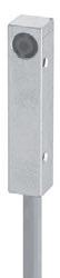
Detailed data sheets for these products can be found on the Contrinex website: 51WWW.CONTRINEX.COM CABLE ** CONNECTOR FREQUENCYSWITCHING(Hz) MOUNTING TEMPERATUREAMBIENT DEGREE PROTECTIONOF PART REFERENCE* (SEEACCESSORIESPAGE50)EMB. NON-EMB.VIEW DATASHEETSINDUCTIVE www.contrinex.com/collections/inductive-miniature MINIATURE PVC 800 Quasi-embed. −25 +70°C IP67 DW-AD-503-04 EH 800 Quasi-embed. −25 +70°C IP67 DW-AS-503-04 AEH PVC 800 Quasi-embed. −25 +70°C IP67 DW-AD-503-M5 EH 800 Quasi-embed. −25 +70°C IP67 DW-AS-503-M5 AEH PUR 8,000 Embed. −25 +70°C IP67 DW-AD-623-03-960 EH PUR 5,000 Embed. −25 +70°C IP67 DW-AD-603-03 EH PUR 3,000 Embed. −25 +70°C IP67 DW-AD-623-03 EH 0.2 m PUR 5,000 Embed. −25 +70°C IP67 DW-AV-603-03-276 AEH 0.2 m PUR 3,000 Embed. −25 +70°C IP67 DW-AV-623-03-276 AEH PUR 8,000 Embed. −25 +70°C IP67 DW-AD-623-M4-960 EH PUR 5,000 Embed. −25 +70°C IP67 DW-AD-603-M4 EH PUR 3,000 Embed. −25 … +70°C IP67 DW-AD-623-M4 EH 0.2 m PUR 5,000 Embed. −25 +70°C IP67 DW-AV-603-M4-276 AEH 0.2 m PUR 3,000 Embed. −25 +70°C IP67 DW-AV-623-M4-276 AEH PVC 5,000 Embed. −25 +70°C IP67 DW-AD-603-04 EH PVC 3,000 Embed. −25 +70°C IP67 DW-AD-623-04 EH 5,000 Embed. −25 +70°C IP67 DW-AS-603-04 AEH 3,000 Embed. −25 +70°C IP67 DW-AS-623-04 AEH 0.2 m PUR 5,000 Embed. −25 +70°C IP67 DW-AV-603-04-276 AEH 0.2 m PUR 3,000 Embed. −25 +70°C IP67 DW-AV-623-04-276 AEH PVC 5,000 Embed. −25 +70°C IP67 DW-AD-603-M5 EH PVC 3,000 Embed. −25 +70°C IP67 DW-AD-623-M5 EH 5,000 Embed. −25 +70°C IP67 DW-AS-603-M5 AEH 3,000 Embed. −25 +70°C IP67 DW-AS-623-M5 AEH 0.2 m PUR 5,000 Embed. −25 … +70°C IP67 DW-AV-603-M5-276 AEH 0.2 m PUR 3,000 Embed. −25 +70°C IP67 DW-AV-623-M5-276 AEH
52 INOXFULLCLASSICSFAMILYSERIES600SERIES700 OPERATING DISTANCE (mm) HOUSINGSIZE(mm) HOUSINGLENGTH(mm) MATERIALHOUSING Supply Voltage range 10 30 VDC Output PNP NO* * Other types available: PNP NC, NPN NC ** 2 m length if not specified COMMON INDUCTIVEFEATURES SENSORS MINIATURE CABLES Cable lengths available: 2 m, 5 m, 10 m other customised lengths possible A Group A: M8 3-pin Sub-group: Field attachable connectors Sub-group: Distribution boxes B Group B: M8 4-pin C Group C: M12 4-pin Sub-group: Field attachable connectors Sub-group: Distribution boxes D Group D: M12 AC/DC 3-pin E Group E: Universal mounting brackets Sub-group: Mechanical stops F Group F: Photoelectric mounting brackets G Group G: Photoelectric reflectors H Group H: Sensor tester Go to page 298 for details OUTPUTACCESSORIES DW-A[x]-[x]0[x] Connection [D] Cable [S] Connector [V] Pigtail Output [1] NPN NO [2] NPN NC [3] PNP NO [4] PNP NC Technology Family [5] Extra Distance [6] Classics [7] Full Inox Reference key on page 116 We made these pages with care, but we decline liability for any errors or omissions. ∅ 4 30 Stainless steel V2A ∅ 4 30 Stainless steel V2A M5 30 Stainless steel V2A M5 30 Stainless steel V2A 5 × 5 (C5) 25 Nickel-chrome-platedbrass 5 × 5 (C5) 25 Nickel-chrome-platedbrass 5 × 5 (C5) 25 Nickel-chrome-platedbrass 5 × 5 (C5) 25 Nickel-chrome-platedbrass


Detailed data sheets for these products can be found on the Contrinex website: 53WWW.CONTRINEX.COM CABLE ** CONNECTOR FREQUENCYSWITCHING(Hz) MOUNTING TEMPERATUREAMBIENT DEGREE PROTECTIONOF PART REFERENCE* (SEEACCESSORIESPAGE52)EMB. NON-EMB. MINIATUREVIEW DATASHEETSINDUCTIVE www.contrinex.com/collections/inductive-miniature PUR 1,200 Non-embed. −25 +85°C IP67 DW-AD-713-04 EH 0.2 m PUR 1,200 Non-embed. −25 +85°C IP67 DW-AV-713-04-276 AEH PUR 1,200 Non-embed. −25 +85°C IP67 DW-AD-713-M5 EH 0.2 m PUR 1,200 Non-embed. −25 +85°C IP67 DW-AV-713-M5-276 AEH PUR 5,000 Embed. −25 +70°C IP67 DW-AD-603-C5 H PUR 3,000 Embed. −25 +70°C IP67 DW-AD-623-C5 H 0.2 m PUR 5,000 Embed. −25 +70°C IP67 DW-AV-603-C5-276 AH 0.2 m PUR 3,000 Embed. −25 +70°C IP67 DW-AV-623-C5-276 AH

Tools for machining metal components Mixing, lifting and tipping mechanisms INDUSTRIES
Automotive production and supply, machine tool, maritime, vehicles, packaging, logistics, materials handling
APPLICATION
Automotive
Rugged inductive sensors confirm engagement of safety interlocks on hooklift trucks A hooklift truck utilizes a hydraulic system for loading and unloading a demountable container. Once the con tainer is correctly positioned on the vehicle’s load bed, interlocks engage with its base, securing it in position. Rugged sensor systems detect full engagement of the interlocks, ensuring the truck is safely loaded prior to driving away. Sensors must be mechanically robust and withstand harsh outdoor conditions. part sensing Packaging systems


Only the toughest sensors survive the most extreme environments. Thanks to one-piece stainless-steel (V2A /AISI 303) construction and a hermetically sealed cable entry, Extreme sensors are corrosionresistant, impervious to oil, and pressure-resistant to 100 bar Rugged, reliable and highly accurate, the Extreme range is at home in the most challenging circumstances. PRODUCT OVERVIEW Housing size mm M8 M12 M18 M30 C23 Full Inox (sn mm) 3 6 2 15 5 20 10 40 7 ACCESSORIES Go to page 298 to see all the accessories KEY ADVANTAGES 9 Mechanically and chemically extremely robust 9 Corrosion resistant 9 IP68 and IP69K, water resistant 9 Pressure resistant up to 100 bar (1,451 psi) 9 INDUCTIVE EXTREMESENSORSEXTREMEDURABILITYINHARSHENVIRONMENTS Cables Mounting brackets


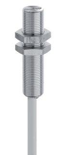
56 FAMILYFULLINOX–SERIES700 OPERATING DISTANCE (mm) HOUSINGSIZE(mm) HOUSINGLENGTH(mm) MATERIALHOUSING CABLES Cable lengths available: 2 m, 5 m, 10 m other customised lengths possible INDUCTIVE SENSORS EXTREME A Group A: M8 3-pin Sub-group: Field attachable connectors Sub-group: Distribution boxes B Group B: M8 4-pin C Group C: M12 4-pin Sub-group: Field attachable connectors Sub-group: Distribution boxes D Group D: M12 AC/DC 3-pin E Group E: Universal mounting brackets Sub-group: Mechanical stops F Group F: Photoelectric mounting brackets G Group G: Photoelectric reflectors H Group H: Sensor tester Go to page 298 for details ACCESSORIES Supply Voltage range 10 30 VDC Output PNP NO* * Other types available: PNP NC, NPN NC ** Pigtail versions available COMMON FEATURES OUTPUT DW-A[x]-70[x] Connection [D] Cable [S] Connector [V] Pigtail Output [1] NPN NO [2] NPN NC [3] PNP NO [4] PNP NC Reference key on page 116 We made these pages with care, but we decline liability for any errors or omissions. M8 45 Stainless steel V2A M8 60 Stainless steel V2A M8 45 Stainless steel V2A M8 60 Stainless steel V2A M8 66 Stainless steel V2A M8 66 Stainless steel V2A M12 50 Stainless steel V2A M12 60 Stainless steel V2A M12 50 Stainless steel V2A M12 60 Stainless steel V2A M12 50 Stainless steel V2A M12 60 Stainless steel V2A M12 50 Stainless steel V2A M12 60 Stainless steel V2A M12 60 Stainless steel V2A M12 50 Stainless steel V2A M12 60 Stainless steel V2A M12 60 Stainless steel V2A M18 50 Stainless steel V2A M18 63.5 Stainless steel V2A M18 50 Stainless steel V2A M18 63.5 Stainless steel V2A M18 50 Stainless steel V2A M18 63.5 Stainless steel V2A M18 63.5 Stainless steel V2A M18 35 Stainless steel V2A M18 48.5 Stainless steel V2A M18 35 Stainless steel V2A M30 50 Stainless steel V2A M30 63.5 Stainless steel V2A


EH 200 Non-embed. −25 +85°C IP68 / IP69K DW-AS-713-M18-002 CEH PUR
Detailed data sheets for these products can be found on the Contrinex website: 57WWW.CONTRINEX.COM CABLE ** CONNECTOR ** FREQUENCYSWITCHING(Hz) MOUNTING TEMPERATUREAMBIENT DEGREE PROTECTIONOF PART REFERENCE* (SEEACCESSORIESPAGE56)EMB. NON-EMB.VIEW DATASHEETSINDUCTIVE www.contrinex.com/collections/inductive-extreme EXTREME PUR 1,200 Embed. −25 +85°C IP68 / IP69K DW-AD-703-M8 EH 1,200 Embed. −25 +85°C IP68 / IP69K DW-AS-703-M8-001 AEH PUR 700 Non-embed. −25 +85°C IP68 / IP69K DW-AD-713-M8 EH 700 Non-embed. −25 +85°C IP68 / IP69K DW-AS-713-M8-001 AEH 1,200 Embed. −25 +85°C IP68 / IP69K DW-AS-703-M8 CEH 700 Non-embed. −25 +85°C IP68 / IP69K DW-AS-713-M8 CEH PUR 600 Embed. −25 +85°C IP68 / IP69K DW-AD-703-M12 EH 600 Embed. −25 … +85°C IP68 / IP69K DW-AS-703-M12 CEH PUR 400 Non-embed. −25 +85°C IP68 / IP69K DW-AD-713-M12 EH 400 Non-embed. −25 +85°C IP68 / IP69K DW-AS-713-M12 CEH PUR 900 Embed. −25 +85°C IP68 / IP69K DW-AD-703-M12-303 EH 900 Embed. −25 … +85°C IP68 / IP69K DW-AS-703-M12-303 CEH PUR 600 Non-embed. −25 +85°C IP68 / IP69K DW-AD-713-M12-303 EH 600 Non-embed. −25 +85°C IP68 / IP69K DW-AS-713-M12-303 CEH 300 Non-embed. −25 +85°C IP68 / IP69K DW-AS-733-M12 CEH PUR 300 Non-embed. −25 +85°C IP68 / IP69K DW-AD-733-M12 EH 300 Non-embed. −25 +85°C IP68 / IP69K DW-AS-73A-M12 CEH 600 Embed. −25 +85°C IP68 / IP69K DW-AS-70A-M12 CEH
PUR 200 Non-embed. −25 … +85°C IP68 / IP69K DW-AD-713-M18 500 Embed. Non-embed. DW-AS-713-M18-303 DW-AD-703-M18-120 Embed. Embed. Embed.
−25 +85°C IP68 / IP69K DW-AS-703-M30-002 CEH
−25 +85°C IP68 / IP69K DW-AS-703-M18-303 CEH 400
PUR 200 Embed. −25 +85°C IP68 / IP69K DW-AD-703-M18 EH 200 Embed. −25 +85°C IP68 / IP69K DW-AS-703-M18-002 CEH
−25 … +85°C IP68 / IP69K
CEH PUR 200 Embed. −25 +85°C IP68 / IP69K
−25 +85°C IP68 / IP69K DW-AS-703-M18-120 CEH PUR 200
−25 +85°C IP68 / IP69K DW-AD-703-M18-226 EH PUR 125 Embed. −25 +85°C IP68 / IP69K DW-AD-703-M30 EH 125
Embed. −25 +85°C IP68 / IP69K DW-AD-703-M18-303 EH 500
EH 200
58 FAMILYFULLINOX–SERIES700 OPERATING DISTANCE (mm) HOUSINGSIZE(mm) HOUSINGLENGTH(mm) MATERIALHOUSING CABLES Cable lengths available: 2 m, 5 m, 10 m other customised lengths possible INDUCTIVE SENSORS EXTREME A Group A: M8 3-pin Sub-group: Field attachable connectors Sub-group: Distribution boxes B Group B: M8 4-pin C Group C: M12 4-pin Sub-group: Field attachable connectors Sub-group: Distribution boxes D Group D: M12 AC/DC 3-pin E Group E: Universal mounting brackets Sub-group: Mechanical stops F Group F: Photoelectric mounting brackets G Group G: Photoelectric reflectors H Group H: Sensor tester Go to page 298 for details ACCESSORIES Supply Voltage range 10 30 VDC Output PNP NO* * Other types available: PNP NC, NPN NC ** Pigtail versions available COMMON FEATURES OUTPUT DW-A[x]-70[x] Connection [D] Cable [S] Connector [V] Pigtail Output [1] NPN NO [2] NPN NC [3] PNP NO [4] PNP NC Reference key on page 116 We made these pages with care, but we decline liability for any errors or omissions. M30 50 Stainless steel V2A M30 63.5 Stainless steel V2A M30 50 Stainless steel V2A M30 63.5 Stainless steel V2A 32 × 20 (C23) 8 Stainless steel V2A

Detailed data sheets for these products can be found on the Contrinex website: 59WWW.CONTRINEX.COM CABLE ** CONNECTOR ** FREQUENCYSWITCHING(Hz) MOUNTING TEMPERATUREAMBIENT DEGREE PROTECTIONOF PART REFERENCE* (SEEACCESSORIESPAGE58)EMB. NON-EMB.VIEW DATASHEETSINDUCTIVE www.contrinex.com/collections/inductive-extreme EXTREME PUR 90 Non-embed. −25 +85°C IP68 / IP69K DW-AD-713-M30 EH 90 Non-embed. −25 +85°C IP68 / IP69K DW-AS-713-M30-002 CEH PUR 250 Embed. −25 +85°C IP68 / IP69K DW-AD-703-M30-303 EH 250 Embed. −25 +85°C IP68 / IP69K DW-AS-703-M30-303 CEH PVC 180 Embed. −25 +85°C IP68 / IP69K DW-AD-703-C23 H

Distance monitoring for position control Drive-belt tension monitoring INDUSTRIES Machine tool, packaging, logistics, materials handling, textile, printing, metal sorting, quality control, vibration monitoring APPLICATION High-resolution analog inductive sensor measures thickness of moving textile webs A specialized textile-testing machine measures the thickness of a moving textile web continuously and in real time. As the web passes over a roller, a precision analog inductive sensor, positioned directly above the roller, rests lightly on the top of the web. By sensing the distance through the material to the roller, the sensor measures the thickness of the web. Machine tools Logistics systems


Best-in-class temperature stability and a measurement range of zero to 40 mm make the Contrinex Analog Output sensor range ideally suited for measuring linear, angular and rotational position. With detection accuracy in the micron range and the best long-range sensing capability on the market, these sensors offer world-class performance with an attractive total cost of ownership. PRODUCT OVERVIEW Housing size mm C8 M8 M12 M18 M30 Extra Distance (sn mm) 0 4 0 4 0 6 0 20 0 40 ACCESSORIES Go to page 298 to see all the accessories KEY ADVANTAGES 9 Longest sensing ranges 9 Best temperature stability 9 Excellent repeat accuracy 9 Resolution in µm range 9 Current or voltage output INDUCTIVE ANALOGSENSORSOUTPUTANALOGOUTPUTFORDISTANCECONTROL Cables Mounting brackets


62 FAMILYEXTRADISTANCE–SERIES500 OPERATING DISTANCE (mm) HOUSINGSIZE(mm) HOUSINGLENGTH(mm) MATERIALHOUSING Supply Voltage range 15 30 VDC COMMON INDUCTIVEFEATURE SENSORS ANALOG OUTPUT CABLES Cable lengths available: 2 m, 5 m, 10 m other customised lengths possible A Group A: M8 3-pin Sub-group: Field attachable connectors Sub-group: Distribution boxes B Group B: M8 4-pin C Group C: M12 4-pin Sub-group: Field attachable connectors Sub-group: Distribution boxes D Group D: M12 AC/DC 3-pin E Group E: Universal mounting brackets Sub-group: Mechanical stops F Group F: Photoelectric mounting brackets G Group G: Photoelectric reflectors H Group H: Sensor tester Go to page 298 for details OUTPUTACCESSORIES DW-A[x]-50[x] Connection [D] Cable [S] Connector Output [9] Analog Reference key on page 116 We made these pages with care, but we decline liability for any errors or omissions. 8 × 8 (C8) 50 Chrome-platedbrass 8 × 8 (C8) 59 Chrome-platedbrass M8 45 Chrome-platedbrass M8 45 Chrome-platedbrass M8 60 Chrome-platedbrass M8 60 Chrome-platedbrass M12 50 Chrome-platedbrass M12 35 Chrome-platedbrass M12 35 Chrome-platedbrass M12 50 Chrome-platedbrass M12 60 Chrome-platedbrass M12 45 Chrome-platedbrass M12 45 Chrome-platedbrass M12 60 Chrome-platedbrass M18 50 Chrome-platedbrass M18 35 Chrome-platedbrass M18 35 Chrome-platedbrass M18 50 Chrome-platedbrass M18 40 Chrome-platedbrass M18 25 Chrome-platedbrass M18 25 Chrome-platedbrass M18 40 Chrome-platedbrass M18 63.5 Chrome-platedbrass M18 48.5 Chrome-platedbrass M18 48.5 Chrome-platedbrass M18 63.5 Chrome-platedbrass M18 63.5 Chrome-platedbrass M18 48.5 Chrome-platedbrass M18 48.5 Chrome-platedbrass M18 63.5 Chrome-platedbrass


Detailed data sheets for these products can be found on the Contrinex website: 63WWW.CONTRINEX.COM CABLE CONNECTOR OUTPUT 1 OUTPUT 2 MOUNTING TEMPERATUREAMBIENT DEGREE PROTECTIONOF PART REFERENCE (SEEACCESSORIESPAGE62)EMB. NON-EMB.VIEW DATASHEETSINDUCTIVE www.contrinex.com/collections/inductive-analog-output ANALOG OUTPUT PUR 0 10 V Quasi-embed. −25 +70°C IP67 DW-AD-509-C8-390 H 0 10 V Quasi-embed. −25 +70°C IP67 DW-AS-509-C8-390 AH PUR 0 5 V Quasi-embed. −25 +70°C IP67 DW-AD-509-M8 EH PUR 0 10 V Quasi-embed. −25 +70°C IP67 DW-AD-509-M8-390 EH 0 5 V Quasi-embed. −25 +70°C IP67 DW-AS-509-M8-001 AEH 0 10 V Quasi-embed. −25 +70°C IP67 DW-AS-509-M8-390 AEH PUR 0 5 V 1 5 mA Quasi-embed. −25 +70°C IP67 DW-AD-509-M12 EH PUR 0 … 5 V 1 … 5 mA Quasi-embed. −25 … +70°C IP67 DW-AD-509-M12-120 EH PUR 0 10 V Quasi-embed. −25 +70°C IP67 DW-AD-509-M12-320 EH PUR 0 10 V 4 20 mA Quasi-embed. −25 +70°C IP67 DW-AD-509-M12-390 CEH 0 5 V 1 5 mA Quasi-embed. −25 +70°C IP67 DW-AS-509-M12 EH 0 5 V 1 5 mA Quasi-embed. −25 +70°C IP67 DW-AS-509-M12-120 CEH 0 10 V Quasi-embed. −25 +70°C IP67 DW-AS-509-M12-320 CEH 0 10 V 4 20 mA Quasi-embed. −25 +70°C IP67 DW-AS-509-M12-390 CEH PUR 0 5 V 1 5 mA Quasi-embed. −25 +70°C IP67 DW-AD-509-M18 EH PUR 0 5 V 1 5 mA Quasi-embed. −25 +70°C IP67 DW-AD-509-M18-120 EH PUR 0 10 V 4 20 mA Quasi-embed. −25 +70°C IP67 DW-AD-509-M18-320 EH PUR 0 10 V 4 20 mA Quasi-embed. −25 +70°C IP67 DW-AD-509-M18-390 EH PUR 0 5 V 1 5 mA Non-embed. −25 +70°C IP67 DW-AD-519-M18 EH PUR 0 5 V 1 5 mA Non-embed. −25 +70°C IP67 DW-AD-519-M18-120 EH PUR 0 … 10 V 4 … 20 mA Non-embed. −25 … +70°C IP67 DW-AD-519-M18-320 EH PUR 0 10 V 4 20 mA Non-embed. −25 +70°C IP67 DW-AD-519-M18-390 EH 0 5 V 1 5 mA Quasi-embed. −25 +70°C IP67 DW-AS-509-M18-002 CEH 0 5 V 1 5 mA Quasi-embed. −25 +70°C IP67 DW-AS-509-M18-120 CEH 0 … 10 V 4 … 20 mA Quasi-embed. −25 … +70°C IP67 DW-AS-509-M18-320 CEH 0 10 V 4 20 mA Quasi-embed. −25 +70°C IP67 DW-AS-509-M18-390 CEH 0 5 V 1 5 mA Non-embed. −25 +70°C IP67 DW-AS-519-M18-002 CEH 0 5 V 1 5 mA Non-embed. −25 +70°C IP67 DW-AS-519-M18-120 CEH 0 10 V 4 20 mA Non-embed. −25 +70°C IP67 DW-AS-519-M18-320 CEH 0 10 V 4 20 mA Non-embed. −25 +70°C IP67 DW-AS-519-M18-390 CEH
64 FAMILYEXTRADISTANCE–SERIES500 OPERATING DISTANCE (mm) HOUSINGSIZE(mm) HOUSINGLENGTH(mm) MATERIALHOUSING Supply Voltage range 15 30 VDC COMMON INDUCTIVEFEATURE SENSORS ANALOG OUTPUT CABLES Cable lengths available: 2 m, 5 m, 10 m other customised lengths possible A Group A: M8 3-pin Sub-group: Field attachable connectors Sub-group: Distribution boxes B Group B: M8 4-pin C Group C: M12 4-pin Sub-group: Field attachable connectors Sub-group: Distribution boxes D Group D: M12 AC/DC 3-pin E Group E: Universal mounting brackets Sub-group: Mechanical stops F Group F: Photoelectric mounting brackets G Group G: Photoelectric reflectors H Group H: Sensor tester Go to page 298 for details OUTPUTACCESSORIES DW-A[x]-50[x] Connection [D] Cable [S] Connector Output [9] Analog Reference key on page 116 We made these pages with care, but we decline liability for any errors or omissions. M30 60 Chrome-platedbrass M30 35 Chrome-platedbrass M30 35 Chrome-platedbrass M30 60 Chrome-platedbrass M30 50 Chrome-platedbrass M30 25 Chrome-platedbrass M30 25 Chrome-platedbrass M30 50 Chrome-platedbrass M30 73.5 Chrome-platedbrass M30 48.5 Chrome-platedbrass M30 48.5 Chrome-platedbrass M30 73.5 Chrome-platedbrass M30 73.5 Chrome-platedbrass M30 48.5 Chrome-platedbrass M30 48.5 Chrome-platedbrass M30 73.5 Chrome-platedbrass

Detailed data sheets for these products can be found on the Contrinex website: 65WWW.CONTRINEX.COM CABLE CONNECTOR OUTPUT 1 OUTPUT 2 MOUNTING TEMPERATUREAMBIENT DEGREE PROTECTIONOF PART REFERENCE (SEEACCESSORIESPAGE64)EMB. NON-EMB.VIEW DATASHEETSINDUCTIVE www.contrinex.com/collections/inductive-analog-output ANALOG OUTPUT PUR 0 5 V 1 5 mA Quasi-embed. −25 +70°C IP67 DW-AD-509-M30 EH PUR 0 5 V 1 5 mA Quasi-embed. −25 +70°C IP67 DW-AD-509-M30-120 EH PUR 0 10 V 4 10 mA Quasi-embed. −25 +70°C IP67 DW-AD-509-M30-320 EH PUR 0 10 V 4 20 mA Quasi-embed. −25 +70°C IP67 DW-AD-509-M30-390 EH PUR 0 5 V 1 5 mA Non-embed. −25 +70°C IP67 DW-AD-519-M30 EH PUR 0 5 V 1 5 mA Non-embed. −25 +70°C IP67 DW-AD-519-M30-120 EH PUR 0 10 V 4 10 mA Non-embed. −25 +70°C IP67 DW-AD-519-M30-320 EH PUR 0 … 10 V 4 … 20 mA Non-embed. −25 … +70°C IP67 DW-AD-519-M30-390 EH 0 5 V 1 5 mA Quasi-embed. −25 +70°C IP67 DW-AS-509-M30-002 CEH 0 5 V 1 5 mA Quasi-embed. −25 +70°C IP67 DW-AS-509-M30-120 CEH 0 10 V 4 10 mA Quasi-embed. −25 +70°C IP67 DW-AS-509-M30-320 CEH 0 … 10 V 4 … 20 mA Quasi-embed. −25 … +70°C IP67 DW-AS-509-M30-390 CEH 0 5 V 1 5 mA Non-embed. −25 +70°C IP67 DW-AS-519-M30-002 CEH 0 5 V 1 5 mA Non-embed. −25 +70°C IP67 DW-AS-519-M30-120 CEH 0 10 V 4 10 mA Non-embed. −25 +70°C IP67 DW-AS-519-M30-320 CEH 0 10 V 4 20 mA Non-embed. −25 +70°C IP67 DW-AS-519-M30-390 CEH

Automotive part sensing Spindle-cutting machine tool INDUSTRIES Automotive production and supply, machine tool, packaging, logistics, materials handling, textile APPLICATION Inductive sensors confirm retraction of stabilizer legs in mobile cranes A manufacturer of mobile cranes uses two-wire inductive sensors with N.C. output function to detect the position of stabilizer legs as part of the vehicle safety system. Before the system will allow the driver to drive the vehi cle away, sensors confirm that stabilizer legs have been retracted. Textile spinning machine automation Logistics


The 2 Wire range of DC, AC/DC and NAMUR sensors is constructed on the Classics technology platform and includes sizes from ∅ 3 to M30, plus a 5 × 5 mm square-section type. Devices are available for embeddable or non-embeddable mounting and connection is by means of cable or connector. With a sensing range up to 15 mm, Contrinex 2 Wire sensors ensure optimal equipment utilization. PRODUCT OVERVIEW Housing size mm ∅ 3 M4 ∅ 4 M5 C5 ∅ 6.5 M8 M12 M18 M30 Classics (sn mm) 0.6 0.6 0.8 0.8 0.8 1.5 1.5 / 2.5 2 / 4 5 / 8 10 / 15 ACCESSORIES Go to page 298 to see all the accessories KEY ADVANTAGES 9 Two-wire sensors for series connection 9 Sizes from ∅ 3 mm to M30 and 5 × 5 mm 9 DC and AC/ DC types 9 NAMUR types with switching frequencies up to 10,000 Hz INDUCTIVE SENSORS2-WIREEASYINSTALLATION AND HIGH SWITCHING FREQUENCY Cables Mounting brackets


68 FAMILYCLASSICS–SERIES600 OPERATING DISTANCE (mm) HOUSINGSIZE(mm) HOUSINGLENGTH(mm) MATERIALHOUSING INDUCTIVE SENSORS 2-WIRE CABLES Cable lengths available: 2 m, 5 m, 10 m other customised lengths possible A Group A: M8 3-pin Sub-group: Field attachable connectors Sub-group: Distribution boxes B Group B: M8 4-pin C Group C: M12 4-pin Sub-group: Field attachable connectors Sub-group: Distribution boxes D Group D: M12 AC/DC 3-pin E Group E: Universal mounting brackets Sub-group: Mechanical stops F Group F: Photoelectric mounting brackets G Group G: Photoelectric reflectors H Group H: Sensor tester Go to page 298 for details ACCESSORIES Output NO or NAMUR * Other type available: NC COMMON FEATURES OUTPUT Go to page 116 for details We made these pages with care, but we decline liability for any errors or omissions. ∅ 3 22 Stainless steel V2A ∅ 3 22 Stainless steel V2A M4 22 Stainless steel V2A M4 22 Stainless steel V2A ∅ 4 25 Stainless steel V2A ∅ 4 38 Stainless steel V2A M5 25 Stainless steel V2A M5 38 Stainless steel V2A 5 × 5 (C5) 25 Nickel-chrome-platedbrass 5 × 5 (C5) 25 Nickel-chrome-platedbrass ∅ 6.5 16 Stainless steel V2A ∅ 6.5 35 Stainless steel V2A ∅ 6.5 35 Stainless steel V2A M8 16 Stainless steel V2A M8 35 Stainless steel V2A M8 35 Stainless steel V2A M8 45 Stainless steel V2A M8 45 Stainless steel V2A M8 45 Stainless steel V2A M8 45 Stainless steel V2A M8 35 Stainless steel V2A M8 45 Stainless steel V2A M12 50 Chrome-platedbrass M12 60 Chrome-platedbrass M12 50 Chrome-platedbrass M12 60 Chrome-platedbrass M12 50 Chrome-platedbrass M12 60 Chrome-platedbrass M12 35 Chrome-platedbrass M12 45 Chrome-platedbrass


Detailed data sheets for these products can be found on the Contrinex website: 69WWW.CONTRINEX.COM CABLE CONNECTOR VOLTAGESUPPLY FREQUENCYSWITCHING(Hz) MOUNTING TEMPERATUREAMBIENT DEGREE PROTECTIONOF PART REFERENCE* (SEEACCESSORIESPAGE68)EMB.DATASHEETSVIEWNON-EMB.INDUCTIVE www.contrinex.com/collections/inductive-2-wire 2-WIRE PUR 7.7 9 VDC 10,000 Embed. −25 +70°C IP67 DW-AD-605-03 E 7.7 9 VDC 10,000 Embed. −25 +70°C IP67 DW-AS-605-03 AE PUR 7.7 9 VDC 10,000 Embed. −25 +70°C IP67 DW-AD-605-M4 E 7.7 9 VDC 10,000 Embed. −25 +70°C IP67 DW-AS-605-M4 AE PVC 7.7 9 VDC 10,000 Embed. −25 +70°C IP67 DW-AD-605-04 E 7.7 9 VDC 10,000 Embed. −25 +70°C IP67 DW-AS-605-04 AE PVC 7.7 9 VDC 10,000 Embed. −25 +70°C IP67 DW-AD-605-M5 E 7.7 … 9 VDC 10,000 Embed. −25 … +70°C IP67 DW-AS-605-M5 AE PUR 7.7 9 VDC 10,000 Embed. −25 +70°C IP67 DW-AD-605-C5 7.7 9 VDC 10,000 Embed. −25 +70°C IP67 DW-AS-605-C5 A PVC 7.7 9 VDC 10,000 Embed. −25 +70°C IP67 DW-AD-605-065-120 E PVC 10 65 VDC 5,000 Embed. −25 +70°C IP67 DW-DD-605-065 EH PVC 10 65 VDC 5,000 Embed. −25 +70°C IP67 DW-DD-625-065 EH PVC 7.7 9 VDC 10,000 Embed. −25 +70°C IP67 DW-AD-605-M8-120 E PVC 10 65 VDC 5,000 Embed. −25 +70°C IP67 DW-DD-605-M8 EH PVC 10 65 VDC 5,000 Non-embed. −25 +70°C IP67 DW-DD-615-M8 EH 10 65 VDC 5,000 Embed. −25 +70°C IP67 DW-DS-605-M8 CEH 10 65 VDC 5,000 Embed. −25 +70°C IP67 DW-DS-605-M8-001 AEH 10 65 VDC 5,000 Non-embed. −25 +70°C IP67 DW-DS-615-M8 CEH 10 65 VDC 5,000 Non-embed. −25 +70°C IP67 DW-DS-615-M8-001 AEH PVC 10 … 65 VDC 5,000 Embed. −25 … +70°C IP67 DW-DD-625-M8 EH 10 65 VDC 5,000 Embed. −25 +70°C IP67 DW-DS-625-M8-001 AEH PVC 10 65 VDC 3,000 Embed. −25 +70°C IP67 DW-DD-605-M12 EH 10 65 VDC 3,000 Embed. −25 +70°C IP67 DW-DS-605-M12 CEH PVC 10 65 VDC 2,500 Non-embed. −25 +70°C IP67 DW-DD-615-M12 EH 10 65 VDC 2,500 Non-embed. −25 +70°C IP67 DW-DS-615-M12 CEH PVC 10 65 VDC 2,000 Embed. −25 +70°C IP67 DW-DD-625-M12 EH 10 65 VDC 2,000 Embed. −25 +70°C IP67 DW-DS-625-M12 CEH PVC 10 65 VDC 2,000 Embed. −25 +70°C IP67 DW-DD-625-M12-120 EH 10 65 VDC 2,000 Embed. −25 +70°C IP67 DW-DS-625-M12-120 CEH
70 FAMILYCLASSICS–SERIES600 OPERATING DISTANCE (mm) HOUSINGSIZE(mm) HOUSINGLENGTH(mm) MATERIALHOUSING INDUCTIVE SENSORS 2-WIRE CABLES Cable lengths available: 2 m, 5 m, 10 m other customised lengths possible A Group A: M8 3-pin Sub-group: Field attachable connectors Sub-group: Distribution boxes B Group B: M8 4-pin C Group C: M12 4-pin Sub-group: Field attachable connectors Sub-group: Distribution boxes D Group D: M12 AC/DC 3-pin E Group E: Universal mounting brackets Sub-group: Mechanical stops F Group F: Photoelectric mounting brackets G Group G: Photoelectric reflectors H Group H: Sensor tester Go to page 298 for details ACCESSORIES Output NO or NAMUR * Other type available: NC COMMON FEATURES OUTPUT Go to page 116 for details We made these pages with care, but we decline liability for any errors or omissions. M12 35 Chrome-platedbrass M12 45 Chrome-platedbrass M12 35 Chrome-platedbrass M12 45 Chrome-platedbrass M12 50 Chrome-platedbrass M12 35 Chrome-platedbrass M12 50 Chrome-platedbrass M12 35 Chrome-platedbrass M12 50 Chrome-platedbrass M12 50 Chrome-platedbrass M12 50 Chrome-platedbrass M12 60 Chrome-platedbrass M12 60 Chrome-platedbrass M12 60 Chrome-platedbrass M18 50 Chrome-platedbrass M18 63.5 Chrome-platedbrass M18 50 Chrome-platedbrass M18 63.5 Chrome-platedbrass M18 50 Chrome-platedbrass M18 63.5 Chrome-platedbrass M18 35 Chrome-platedbrass M18 48.5 Chrome-platedbrass M18 35 Chrome-platedbrass M18 48.5 Chrome-platedbrass M18 35 Chrome-platedbrass M18 48.5 Chrome-platedbrass M18 50 Chrome-platedbrass M18 35 Chrome-platedbrass M18 50 Chrome-platedbrass M18 50 Chrome-platedbrass
Detailed data sheets for these products can be found on the Contrinex website: 71WWW.CONTRINEX.COM CABLE CONNECTOR VOLTAGESUPPLY FREQUENCYSWITCHING(Hz) MOUNTING TEMPERATUREAMBIENT DEGREE PROTECTIONOF PART REFERENCE* (SEEACCESSORIESPAGE70)EMB.DATASHEETSVIEWNON-EMB.INDUCTIVE www.contrinex.com/collections/inductive-2-wire 2-WIRE PVC 10 65 VDC 3,000 Embed. −25 +70°C IP67 DW-DD-605-M12-120 EH 10 65 VDC 3,000 Embed. −25 +70°C IP67 DW-DS-605-M12-120 CEH PVC 10 65 VDC 2,500 Non-embed. −25 +70°C IP67 DW-DD-615-M12-120 EH 10 65 VDC 2,500 Non-embed. −25 +70°C IP67 DW-DS-615-M12-120 CEH PVC 7.7 9 VDC 2,500 Embed. −25 +70°C IP67 DW-AD-605-M12 E PVC 7.7 9 VDC 2,500 Embed. −25 +70°C IP67 DW-AD-605-M12-120 E PVC 7.7 9 VDC 1,000 Non-embed. −25 +70°C IP67 DW-AD-615-M12 E PVC 7.7 … 9 VDC 1,000 Non-embed. −25 … +70°C IP67 DW-AD-615-M12-120 E PVC 20 265/10 320 VAC/VDC 25 Hz AC / 3,000 Hz DC Embed. −25 +70°C IP67 DW-AD-607-M12 EH PVC 20 265/10 320 VAC/VDC 25 Hz AC / 2,000 Hz DC Non-embed. −25 +70°C IP67 DW-AD-617-M12 EH PVC 20 265/10 320 VAC/VDC 25 Hz AC / 2,000 Hz DC Embed. −25 +70°C IP67 DW-AD-627-M12 EH 20 265/10 320 VAC/VDC 25 Hz AC / 3,000 Hz DC Embed. −25 … +70°C IP67 DW-AS-607-M12-069 DEH 20 265/10 320 VAC/VDC 25 Hz AC / 2,000 Hz DC Non-embed. −25 +70°C IP67 DW-AS-617-M12-069 DEH 20 265/10 320 VAC/VDC 25 Hz AC / 2,000 Hz DC Embed. −25 +70°C IP67 DW-AS-627-M12-069 DEH PVC 10 65 VDC 1,500 Embed. −25 +70°C IP67 DW-DD-605-M18 EH 10 65 VDC 1,500 Embed. −25 +70°C IP67 DW-DS-605-M18-002 CEH PVC 10 65 VDC 1,200 Non-embed. −25 +70°C IP67 DW-DD-615-M18 EH 10 65 VDC 1,200 Non-embed. −25 +70°C IP67 DW-DS-615-M18-002 CEH PVC 10 65 VDC 1,000 Quasi-embed. −25 +70°C IP67 DW-DD-625-M18 EH 10 65 VDC 1,000 Quasi-embed. −25 +70°C IP67 DW-DS-625-M18-002 CEH PVC 10 … 65 VDC 1,500 Embed. −25 … +70°C IP67 DW-DD-605-M18-120 EH 10 65 VDC 1,500 Embed. −25 +70°C IP67 DW-DS-605-M18-120 CEH PVC 10 65 VDC 1,200 Non-embed. −25 +70°C IP67 DW-DD-615-M18-120 EH 10 65 VDC 1,200 Non-embed. −25 +70°C IP67 DW-DS-615-M18-120 CEH PVC 10 … 65 VDC 1,000 Quasi-embed. −25 … +70°C IP67 DW-DD-625-M18-120 EH 10 65 VDC 1,000 Quasi-embed. −25 +70°C IP67 DW-DS-625-M18-120 CEH PVC 7.7 9 VDC 1,000 Embed. −25 +70°C IP67 DW-AD-605-M18 E PUR 7.7 9 VDC 1,000 Embed. −25 +70°C IP67 DW-AD-605-M18-120 E PVC 20 265/10 320 VAC/VDC 25 Hz AC / 1,500 Hz DC Embed. −25 +70°C IP67 DW-AD-607-M18 EH PVC 20 265/10 320 VAC/VDC 25 Hz AC / 1,200 Hz DC Non-embed. −25 +70°C IP67 DW-AD-617-M18 EH
72 FAMILYCLASSICS–SERIES600 OPERATING DISTANCE (mm) HOUSINGSIZE(mm) HOUSINGLENGTH(mm) MATERIALHOUSING INDUCTIVE SENSORS 2-WIRE CABLES Cable lengths available: 2 m, 5 m, 10 m other customised lengths possible A Group A: M8 3-pin Sub-group: Field attachable connectors Sub-group: Distribution boxes B Group B: M8 4-pin C Group C: M12 4-pin Sub-group: Field attachable connectors Sub-group: Distribution boxes D Group D: M12 AC/DC 3-pin E Group E: Universal mounting brackets Sub-group: Mechanical stops F Group F: Photoelectric mounting brackets G Group G: Photoelectric reflectors H Group H: Sensor tester Go to page 298 for details ACCESSORIES Output NO or NAMUR * Other type available: NC COMMON FEATURES OUTPUT Go to page 116 for details We made these pages with care, but we decline liability for any errors or omissions. M18 63.5 Chrome-platedbrass M18 63.5 Chrome-platedbrass M30 50 Chrome-platedbrass M30 63.5 Chrome-platedbrass M30 50 Chrome-platedbrass M30 63.5 Chrome-platedbrass M30 35 Chrome-platedbrass M30 48.5 Chrome-platedbrass M30 35 Chrome-platedbrass M30 48.5 Chrome-platedbrass M30 50 Chrome-platedbrass M30 35 Chrome-platedbrass M30 50 Chrome-platedbrass M30 50 Chrome-platedbrass M30 63.5 Chrome-platedbrass M30 63.5 Chrome-platedbrass
Detailed data sheets for these products can be found on the Contrinex website: 73WWW.CONTRINEX.COM CABLE CONNECTOR VOLTAGESUPPLY FREQUENCYSWITCHING(Hz) MOUNTING TEMPERATUREAMBIENT DEGREE PROTECTIONOF PART REFERENCE* (SEEACCESSORIESPAGE72)EMB.DATASHEETSVIEWNON-EMB.INDUCTIVE www.contrinex.com/collections/inductive-2-wire 2-WIRE 20 … 265/10 … 320 VAC/VDC 25 Hz AC / 1,500 Hz DC Embed. −25 +70°C IP67 DW-AS-607-M18-069 DEH 20 265/10 320 VAC/VDC 25 Hz AC / 1,200 Hz DC Non-embed. −25 +70°C IP67 DW-AS-617-M18-069 DEH PVC 10 65 VDC 600 Embed. −25 +70°C IP67 DW-DD-605-M30 EH 10 65 VDC 600 Embed. −25 +70°C IP67 DW-DS-605-M30-002 CEH PVC 10 65 VDC 500 Non-embed. −25 +70°C IP67 DW-DD-615-M30 EH 10 65 VDC 500 Non-embed. −25 +70°C IP67 DW-DS-615-M30-002 CEH PVC 10 65 VDC 600 Embed. −25 +70°C IP67 DW-DD-605-M30-120 EH 10 … 65 VDC 600 Embed. −25 … +70°C IP67 DW-DS-605-M30-120 CEH PVC 10 65 VDC 500 Non-embed. −25 +70°C IP67 DW-DD-615-M30-120 EH 10 65 VDC 500 Non-embed. −25 +70°C IP67 DW-DS-615-M30-120 CEH PVC 7.7 9 VDC 400 Embed. −25 +70°C IP67 DW-AD-605-M30 E PVC 7.7 … 9 VDC 400 Embed. −25 … +70°C IP67 DW-AD-605-M30-120 E PVC 20 265/10 320 VAC/VDC 25 Hz AC / 600 Hz DC Embed. −25 +70°C IP67 DW-AD-607-M30 EH PVC 20 265/10 320 VAC/VDC 25 Hz AC / 500 Hz DC Non-embed. −25 +70°C IP67 DW-AD-617-M30 EH 20 265/10 320 VAC/VDC 25 Hz AC / 600 Hz DC Embed. −25 +70°C IP67 DW-AS-607-M30-069 DEH 20 265/10 320 VAC/VDC 25 Hz AC / 500 Hz DC Non-embed. −25 +70°C IP67 DW-AS-617-M30-069 DEH
Automotive part sensing Machine tools
Pump and valve control
APPLICATION
INDUSTRIES
Automotive production and supply, machine tool, energy, pneumatics, lubrication systems, pumps, valves
Micromechanical grippers
Inductive sensors check presence of correct drilling tool in CNC machine During operation of an automated CNC machining center, pressurized machining fluid lubricates and cools the drill assembly before the tool-changing robot selects the next tool. Standard inductive sensors would be unreli able in this harsh environment. Instead, Extra Pressure sensors are used to check the presence of the correct drilling tool on the robot arm. With increased pressure resistance, a gas-tight sensing face, a protection rat ing of IP68 and PUR cable, these sensors provide high accuracy and long life, even when exposed to pressurized fluids.


Dependable, accurate presenceand position-sensing at pressures up to 200 bar requires worldclass performance and build quality. Contrinex Extra Pressure inductive sensors deliver exactly that, operating continuously in pressurized conditions. The combination of a stainless-steel housing and an impermeably bonded ceramic or sapphire-glass sensing face guarantees robustness and reliability. PRODUCT ACCESSORIESOVERVIEW Go to page 298 to see all the accessories KEY ADVANTAGES 9 Pressure resistant up to 200 bar (2,901 psi) 9 High quality ASIC sensors with interface 9 Mechanically and chemically rugged 9 Impervious: IP68 9 Gas-tight sensing face 9 Miniature devices INDUCTIVE SENSORS EXTRA PRESSURE PRESSURE RESISTANT UP TO 200 BAR (2,901 PSI) Cables Mounting brackets Housing size mm ∅ 3 ∅ 4 ∅ 6.5 M8 snmm Extra Distance 2.5 2.5 Classics 0.8 0.6


76 CLASSICSFAMILYEXTRADISTANCE–SERIES500SERIES600 OPERATING DISTANCE (mm) HOUSINGSIZE(mm) HOUSINGLENGTH(mm) OPERATINGPRESSURE Supply Voltage range 10 30 VDC Housing material Stainless steel V2A COMMON INDUCTIVEFEATURES SENSORS EXTRA PRESSURE CABLES Cable lengths available: 2 m, 5 m, 10 m other customised lengths possible A Group A: M8 3-pin Sub-group: Field attachable connectors Sub-group: Distribution boxes B Group B: M8 4-pin C Group C: M12 4-pin Sub-group: Field attachable connectors Sub-group: Distribution boxes D Group D: M12 AC/DC 3-pin E Group E: Universal mounting brackets Sub-group: Mechanical stops F Group F: Photoelectric mounting brackets G Group G: Photoelectric reflectors H Group H: Sensor tester Go to page 298 for details OUTPUTACCESSORIES DW-A[x]-[x]0[x] Connection [D] Cable [S] Connector [V] Pigtail Output [1] NPN NO [2] NPN NC [3] PNP NO [4] PNP NC Technology Family [5] Extra Distance [6] Classics Reference key on page 116 We made these pages with care, but we decline liability for any errors or omissions. ∅ 6.5 45 ≤ 20 bar ∅ 6.5 45 ≤ 20 bar ∅ 6.5 45 ≤ 20 bar ∅ 6.5 45 ≤ 20 bar M8 45 ≤ 20 bar M8 45 ≤ 20 bar M8 45 ≤ 20 bar M8 45 ≤ 20 bar ∅ 3 12 ≤ 200 bar ∅ 3 12 ≤ 200 bar ∅ 4 25 ≤ 20 bar ∅ 4 25 ≤ 20 bar ∅ 4 25 ≤ 20 bar


Detailed data sheets for these products can be found on the Contrinex website: 77WWW.CONTRINEX.COM CABLE CONNECTOR FREQUENCYSWITCHING(Hz) MOUNTING TEMPERATUREAMBIENT DEGREE PROTECTIONOF PART REFERENCE (SEEACCESSORIESPAGE76)EMB. NON-EMB.VIEW DATASHEETSINDUCTIVE www.contrinex.com/collections/inductive-extra-pressure-up-to-200-bar-peak EXTRA PRESSURE PUR 1,000 Embed. −25 +70°C IP68 DW-AD-501-065E EH PUR 1,000 Embed. −25 +70°C IP68 DW-AD-502-065E EH PUR 1,000 Embed. −25 +70°C IP68 DW-AD-503-065E EH PUR 1,000 Embed. −25 +70°C IP68 DW-AD-504-065E EH PUR 1,000 Embed. −25 +70°C IP68 DW-AD-501-M8E EH PUR 1,000 Embed. −25 +70°C IP68 DW-AD-502-M8E EH PUR 1,000 Embed. −25 +70°C IP68 DW-AD-503-M8E EH PUR 1,000 Embed. −25 … +70°C IP68 DW-AD-504-M8E EH PUR 8,000 Embed. −25 +70°C IP68 / IP69K DW-AD-621-03E-961 EH PUR 8,000 Embed. −25 +70°C IP68 / IP69K DW-AD-623-03E-961 EH PUR 5,000 Embed. −25 +70°C IP68 DW-AD-601-04E EH PUR 5,000 Embed. −25 +70°C IP68 DW-AD-603-04E EH PUR 5,000 Embed. −25 … +70°C IP68 DW-AD-604-04E EH

Hydraulic cylinder control with sensors Valve control for concrete pumps INDUSTRIES Automotive production and supply, machine tool, energy, maritime, hydraulic and fluid power, concrete pumps, injection molding machines APPLICATION Ram position sensing for manual punch-riveting tool A manufacturer of cold-forming tools for joining sheet metal uses position sensing to control the operation of a manual punch-riveting tool. A high-pressure inductive sensor mounted directly into the wall of a small pneumo hydraulic cylinder detects the position of the hydraulic ram, preventing the operating cycle from starting unless the ram is fully retracted. Automotive industry Maritime industry


Contrinex High Pressure inductive sensors are suitable for continuous duty at pressures up to 500 bar (1,000 bar peak pressure), ensuring reliable sensing in the most demanding pneumatic and hydraulic applications. Available with classic metal housing or onepiece, stainless-steel construction, these sensors detect the smallest parts and are ideal for piston-control applications. PRODUCT ACCESSORIESOVERVIEW Go to page 298 to see all the accessories KEY ADVANTAGES 9 Highest operating (500 bar / 7,255 psi) and peak pressure (1,000 bar / 14,510 psi) on the market 9 Resistant to pressure cycles: 50 times longer lifetime under pressure than the market standard 9 Gas-tight sensing face 9 Large temperature range −25°C (−13°F) … +100°C (+212°F) 9 High quality ASIC sensors with interface INDUCTIVE SENSORS HIGH PRESSURE PRESSURE RESISTANT UP TO 500 BAR (7,255 PSI) Cables Mounting brackets Housing size mm M5 / P5 M8 / P8 M12 / P12 M14 / P20 snmm Extra Distance 1 1.5 1.5 2.5 3 Full Inox 1.5

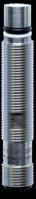
80 FAMILYEXTRADISTANCE–SERIES500 OPERATING DISTANCE (mm) HOUSINGSIZE(mm) HOUSINGLENGTH(mm) MATERIALHOUSING Supply Voltage range 10 30 VDC Output PNP NO* * Other types available: PNP NC, NPN NC ** Pigtail versions available COMMON INDUCTIVEFEATURES SENSORS HIGH PRESSURE CABLES Cable lengths available: 2 m, 5 m, 10 m other customised lengths possible A Group A: M8 3-pin Sub-group: Field attachable connectors Sub-group: Distribution boxes B Group B: M8 4-pin C Group C: M12 4-pin Sub-group: Field attachable connectors Sub-group: Distribution boxes D Group D: M12 AC/DC 3-pin E Group E: Universal mounting brackets Sub-group: Mechanical stops F Group F: Photoelectric mounting brackets G Group G: Photoelectric reflectors H Group H: Sensor tester Go to page 298 for details OUTPUTACCESSORIES DW-A[x]-50[x] Connection [D] Cable [S] Connector [V] Pigtail Output [1] NPN NO [2] NPN NC [3] PNP NO [4] PNP NC Reference key on page 116 We made these pages with care, but we decline liability for any errors or omissions. M5 27 Stainless steel DIN 2.4711 M8 30 Stainless steel V4A M12 78 Stainless steel V2A M12 47 Stainless steel V2A M12 78 Stainless steel V2A M12 43 Stainless steel V2A M12 69 Stainless steel V2A M12 93 Stainless steel V2A M12 138 Stainless steel V2A M12 56 Stainless steel V2A M12 78 Stainless steel V2A M12 56 Stainless steel V2A M12 93 Stainless steel V2A M12 69 Stainless steel V2A M12 93 Stainless steel V2A M12 138 Stainless steel V2A M12 56 Stainless steel V2A M12 78 Stainless steel V2A M12 56 Stainless steel V2A M12 93 Stainless steel V2A M12 69 Stainless steel V2A M12 93 Stainless steel V2A M12 138 Stainless steel V2A M12 56 Stainless steel V2A M12 78 Stainless steel V2A M12 56 Stainless steel V2A M12 93 Stainless steel V2A M14 56 Stainless steel V4A M14 65 Stainless steel V4A


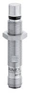

CH 600
CH 600 Embed. −25 +100°C IP68 DW-AS-503-P12-624 CH 600 Embed. −25 +100°C IP68 DW-AS-503-P12-627
CH 600 Embed. −25 +100°C IP68 DW-AS-503-P12-621
−25 +100°C
−25 +100°C
+100°C
CH 600 Embed. −25 +100°C IP68 DW-AS-503-P12-630 Embed. −25 IP68 DW-AS-503-P12-635 Embed. IP68 DW-AS-523-P12 Embed. IP68 DW-AS-523-P12-621 Embed. IP68 DW-AS-523-P12-622 Embed. −25 IP68 DW-AS-523-P12-624 Embed. −25 IP68 DW-AS-523-P12-627 Embed. IP68 DW-AS-523-P12-630 Embed. IP68 DW-AS-523-P12-635 500 Embed. IP68 DW-AD-503-P20 Embed. IP68 DW-AS-503-P20
CH 600
CH 600
CH 600
Detailed data sheets for these products can be found on the Contrinex website: 81WWW.CONTRINEX.COM CABLE ** CONNECTOR ** FREQUENCYSWITCHING(Hz) MOUNTING TEMPERATUREAMBIENT DEGREE PROTECTIONOF PART REFERENCE* (SEEACCESSORIESPAGE80)EMB. NON-EMB.VIEW DATASHEETSINDUCTIVE www.contrinex.com/collections/inductive-high-pressure-up-to-1000-bar-peak HIGH PRESSURE PUR 1,000 Embed. −25 +100°C IP68 DW-AD-503-P5 H PUR 800 Embed. −25 +100°C IP68 DW-AD-503-P8 H PUR 600 Embed. −25 +100°C IP68 DW-AD-503-P12-764 H PUR 600 Embed. −25 +100°C IP68 DW-AD-503-P12-625 H PUR 600 Embed. −25 +100°C IP68 DW-AD-503-P12-627 H PUR 600 Embed. −25 +100°C IP68 DW-AD-503-P12-639 H 600 Embed. −25 +100°C IP68 DW-AS-50A-P12 CH 600 Embed. −25 … +100°C IP68 DW-AS-50A-P12-621 CH 600 Embed. −25 +100°C IP68 DW-AS-50A-P12-622 CH 600 Embed. −25 +100°C IP68 DW-AS-50A-P12-624 CH 600 Embed. −25 +100°C IP68 DW-AS-50A-P12-627 CH 600 Embed. −25 +100°C IP68 DW-AS-50A-P12-630 CH 600 Embed. −25 +100°C IP68 DW-AS-50A-P12-635 CH 600 Embed. −25 +100°C IP68 DW-AS-503-P12
CH 600
CH 600
… +100°C
+100°C
CH 600
CH 600
−25 +100°C
−25 … +100°C
CH PUR
−25 +100°C
CH
−25 +100°C
−25 +100°C
CH 600 Embed. −25 +100°C IP68 DW-AS-503-P12-622
H 500
82 FAMILYFULLINOX–SERIES700 OPERATING DISTANCE (mm) HOUSINGSIZE(mm) HOUSINGLENGTH(mm) MATERIALHOUSING CABLES Cable lengths available: 2 m, 5 m, 10 m other customised lengths possible INDUCTIVE SENSORS HIGH PRESSURE A Group A: M8 3-pin Sub-group: Field attachable connectors Sub-group: Distribution boxes B Group B: M8 4-pin C Group C: M12 4-pin Sub-group: Field attachable connectors Sub-group: Distribution boxes D Group D: M12 AC/DC 3-pin E Group E: Universal mounting brackets Sub-group: Mechanical stops F Group F: Photoelectric mounting brackets G Group G: Photoelectric reflectors H Group H: Sensor tester Go to page 298 for details ACCESSORIES Supply Voltage range 10 30 VDC Output PNP NO* * Other types available: PNP NC, NPN NC ** Pigtail versions available COMMON FEATURES OUTPUT DW-A[x]-70[x] Connection [D] Cable [S] Connector [V] Pigtail Output [1] NPN NO [2] NPN NC [3] PNP NO [4] PNP NC Reference key on page 116 We made these pages with care, but we decline liability for any errors or omissions. M12 57.3 Stainless steel V4A M12 61 Stainless steel V4A


Detailed data sheets for these products can be found on the Contrinex website: 83WWW.CONTRINEX.COM CABLE ** CONNECTOR ** FREQUENCYSWITCHING(Hz) MOUNTING TEMPERATUREAMBIENT DEGREE PROTECTIONOF PART REFERENCE* (SEEACCESSORIESPAGE82)EMB. NON-EMB. HIGH PRESSUREVIEW DATASHEETSINDUCTIVE www.contrinex.com/collections/inductive-high-pressure-up-to-1000-bar-peak PUR 850 Embed. −25 +85°C IP68 / IP69K DW-LD-703-P12G-003 H 850 Embed. −25 +85°C IP68 / IP69K DW-LS-703-P12G CH

Aircraft door monitoring Automotive part sensing INDUSTRIES Automotive production and supply, machine tool, energy, aerospace APPLICATION Reliable presence sensing despite elevated temperature for automated laundry system Highly automated laundry systems use inductive sensors for presence sensing in ironing-lane processes. Temperatures in this environment are too high for stan dard sensors, but pose no problem for temperatureresistant sensors of the Extra Temperature range. They operate reliably at temperatures up to 120°C (248°F), are well protected against ambient humidity (IP67) and include an integral IO-Link interface for communication with modern control and management systems.
MachineAerospacetools


Contrinex Extra Temperature inductive sensors offer the ideal solution for position- and presence-sensing applications at temperatures up to 120°C (248°F). Industrial processes often generate more heat than is suitable for standard sensors. In such environments, the stainless-steel construction and robust electronics of this range ensure reliable, accurate operation and minimal downtime. PRODUCT ACCESSORIESOVERVIEW Go to page 298 to see all the accessories KEY ADVANTAGES 9 Temperature resistant up to +120°C (+248°F) 9 Excellent long term reliability 9 Outstanding accuracy 9 High quality ASIC sensors with interface INDUCTIVE SENSORS TEMPERATURE RESISTANT UP TO +120°C (+248°F) Cables Mounting brackets TEMPERATUREEXTRAHousingsizemm M5 M8 M12 M18 Classics (sn mm) 0.8 4 2 4 5


86 FAMILYCLASSICS–SERIES600 OPERATING DISTANCE (mm) HOUSINGSIZE(mm) HOUSINGLENGTH(mm) MATERIALHOUSING INDUCTIVE SENSORS EXTRA TEMPERATURE CABLES Cable lengths available: 2 m, 5 m, 10 m other customised lengths possible A Group A: M8 3-pin Sub-group: Field attachable connectors Sub-group: Distribution boxes B Group B: M8 4-pin C Group C: M12 4-pin Sub-group: Field attachable connectors Sub-group: Distribution boxes D Group D: M12 AC/DC 3-pin E Group E: Universal mounting brackets Sub-group: Mechanical stops F Group F: Photoelectric mounting brackets G Group G: Photoelectric reflectors H Group H: Sensor tester Go to page 298 for details ACCESSORIES Supply Voltage range 10 30 VDC Output PNP NO* * Other types available: PNP NC, NPN NC ** Pigtail versions available COMMON FEATURES OUTPUT DW-A[x]-60[x] Connection [D] Cable [S] Connector [V] Pigtail Output [1] NPN NO [2] NPN NC [3] PNP NO [4] PNP NC Reference key on page 116 We made these pages with care, but we decline liability for any errors or omissions. M5 25 Stainless steel V2A M5 25 Stainless steel V2A M8 36 Stainless steel V2A M12 44.3 Nickel-plated brass M12 50 Nickel-plated brass M18 35 Chrome-platedbrass


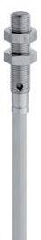


Detailed data sheets for these products can be found on the Contrinex website: 87WWW.CONTRINEX.COM CABLE ** CONNECTOR ** FREQUENCYSWITCHING(Hz) MOUNTING TEMPERATUREAMBIENT DEGREE PROTECTIONOF PART REFERENCE* (SEEACCESSORIESPAGE86)EMB. NON-EMB.VIEW DATASHEETSINDUCTIVE www.contrinex.com/collections/inductive-extra-temperature-up-to-120-c EXTRA TEMPERATURE Silicone 5,000 Embed. −25 +120°C IP67 DW-AD-601-M5-735 EH Silicone 5,000 Embed. −25 +120°C IP67 DW-AD-603-M5-735 EH 3,500 Non-embed. 0 +85°C IP67 DW-AS-633-M8-732 AEH PUR 2,000 Non-embed. −25 +100°C IP67 DW-AD-613-M12-733 EH PVC 3,000 Embed. −25 +100°C IP67 DW-AD-603-M12-734 EH PUR 2,000 Embed. −40 +100°C IP67 DW-AD-603-M18-718 EH

Automated bakery equipment Paintshop in automotive industry INDUSTRIES Automotive production and supply, paint shops, surface treatment, bakery equipment, food and beverage APPLICATION High Temperature inductive sensors monitor position of fire-proof ventilation dampers A manufacturer of fire-resistant air dampers for tunnel ventilation uses High Temperature inductive sensors to monitor damper position. They provide feedback to the ventilation control center, which adjusts dampers and fans as necessary in both normal and emergency oper ation. For reliable operation at temperatures up to 230°C (446°F), sensor electronics are built into a separate M12 stainless-steel housing. Automotive production and supply Brewery production equipment


Exceptional working conditions demand performance,uncompromisingandContrinex High Temperature inductive sensors deliver in every respect. Designed for continuous operation at temperatures up to 180°C (230°C with remote electronics), this range is ideal for the harshest environments, including automotive paint shops, metal-treatment plants and glass manufacturing. PRODUCT ACCESSORIESOVERVIEW Go to page 298 to see all the accessories KEY ADVANTAGES 9 Highest long-term stability due to fully potted electronics 9 Long sensor life 9 Reliable sensing in high-temperature applications 9 Compact construction with integral amplifier for tempera tures up to +180°C (+356°F) 9 External amplifier module for temperatures up to +230°C (+446°F) INDUCTIVE SENSORS TEMPERATURE RESISTANT UP TO +230°C (+446°F) Cables Mounting brackets TEMPERATUREHIGHHousingsizemm M8 M12 M18 M30 M50 Classics (sn mm) 2 3 / 4 5 10 / 15 25


90 FAMILYCLASSICS–SERIES600 OPERATING DISTANCE (mm) HOUSINGSIZE(mm) HOUSINGLENGTH(mm) MATERIALHOUSING INDUCTIVE SENSORS HIGH TEMPERATURE CABLES Cable lengths available: 2 m, 5 m, 10 m other customised lengths possible A Group A: M8 3-pin Sub-group: Field attachable connectors Sub-group: Distribution boxes B Group B: M8 4-pin C Group C: M12 4-pin Sub-group: Field attachable connectors Sub-group: Distribution boxes D Group D: M12 AC/DC 3-pin E Group E: Universal mounting brackets Sub-group: Mechanical stops F Group F: Photoelectric mounting brackets G Group G: Photoelectric reflectors H Group H: Sensor tester Go to page 298 for details ACCESSORIES Supply Voltage range 10 30 VDC Output PNP NO* * Other types available: PNP NC, NPN NC COMMON FEATURES OUTPUT DW-A[x]-60[x] Connection [D] Cable [S] Connector [V] Pigtail Output [1] NPN NO [2] NPN NC [3] PNP NO [4] PNP NC Reference key on page 116 We made these pages with care, but we decline liability for any errors or omissions. M8 60 Stainless steel V2A M12 59 Stainless steel V2A M12 63 Stainless steel V2A M18 82 Stainless steel V2A M18 76 Stainless steel V2A M18 82 Stainless steel V2A M30 72 Stainless steel V2A M30 72 Stainless steel V2A M30 83 Stainless steel V2A M30 83 Stainless steel V2A M30 83 Stainless steel V2A M50 76 Stainless steel V2A M50 55 Stainless steel V2A M50 68 Stainless steel V2A M50 76 Stainless steel V2A


Detailed data sheets for these products can be found on the Contrinex website: 91WWW.CONTRINEX.COM CABLE CONNECTION FREQUENCYSWITCHING(Hz) MOUNTING TEMPERATUREAMBIENT DEGREE PROTECTIONOF PART REFERENCE* (SEEACCESSORIESPAGE90)EMB. NON-EMB.VIEW DATASHEETSINDUCTIVE www.contrinex.com/collections/inductive-high-temperature-up-to-230-c HIGH TEMPERATURE Silicone Silicone, 2 m, 3 wire 600 Embed. 0…+140°C IP67 DW-HD-623-M8-100 H Silicone Silicone, 2 m, 3 wire 500 Embed. 0…+150°C IP67 DW-HD-603-M12-200 H Silicone Silicone, 2 m, 3 wire 500 Non-Embed. 0…+150°C IP67 DW-HD-613-M12-200 H PTFE PTFE, 2 m, 3 wire 400 Embed. 0…+180°C IP67 DW-HD-603-M18-310 H Teflon+PUR PTFE, 3 m + PUR, 2 m, 3 wire 300 Embed. 0…+230°C IP67 DW-HD-603-M18-411 H PTFE PTFE, 2 m, 3 wire 400 Non-embed. 0…+180°C IP67 DW-HD-613-M18-310 H PTFE PTFE, 2 m, 3 wire 200 Embed. 0…+180°C IP67 DW-HD-603-M30-310 H Teflon+PUR PTFE, 3 m + PUR, 2 m, 3 wire 200 Embed. 0…+230°C IP67 DW-HD-603-M30-411 H Teflon+PUR PTFE, 3 m + PUR, 2 m, 3 wire 150 Non-embed. 0…+230°C IP67 DW-HD-613-M30-411 H PTFE PTFE, 2 m, 3 wire 200 Non-embed. 0…+180°C IP67 DW-HD-613-M30-310 H Teflon+PUR PTFE, 5 m + PUR, 2 m, 3 wire 150 Non-embed. 0…+230°C IP67 DW-HD-613-M30-508 H Silicone Silicone, 2 m, 3 wire 100 Quasi-embed. 0…+180°C IP67 DW-HD-603-M50-300 H Teflon+PUR PTFE, 3 m + PUR, 2 m, 3 wire 150 Quasi-embed. 0…+230°C IP67 DW-HD-603-M50-411 H Teflon+PUR PTFE, 3 m + PUR, 2 m, 3 wire 150 Non-Embed. 0…+230°C IP67 DW-HD-613-M50-411 H Silicone Silicone, 2 m, 3 wire 100 Non-embed. 0…+180°C IP67 DW-HD-613-M50-300 H

Welding cell in automotive factory OEM welding equipment INDUSTRIES Automotive production and supply, welding equipment APPLICATION Presence sensing ensures correct part placement on welding machine Weld-Immune inductive sensors ensure that metal panels are correctly located on fixtures prior to welding. The anti-spatter coating, weld-field immunity and impact resistance of these sensors ensure that operation is reliable and downtime negligible, despite the harsh envi ronment. Sensor service-life is increased, while mainte nance costs are reduced significantly. Welding Automotiveequipmentproduction and supply

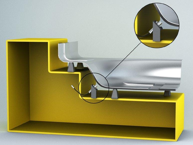


Contrinex Weld-Immune inductive sensors are ideal for the hostile working environments found in automotive factories and other industrial welding plants. Onepiece, stainless-steel construction and best-in-class sensing ranges of up to 16 mm prevent the risk of collision damage. Types with an ACTIVSTONE® coating offer the highest level of weld-spatter resistance, reducing cleaning and maintenance costs. PRODUCT ACCESSORIESOVERVIEW Go to pages 100 and 101 to see all the accessories KEY ADVANTAGES 9 Exceptionally resistant to weld spatter in spot, MIG and MAG applications thanks to Activstone® coating protection 9 Resistant to magnetic interference from medium-frequency weld fields, current up to 15 kA 9 Maximum impact resistance on the Full Inox sensor with one-piece stainless-steel housings and Condet® technology 9 Protection beyond the sensor with coated mounting brackets, spatter-resistant cable and protective tubes INDUCTIVE SENSORS REVOLUTIONARY PROTECTION FOR LONG LIFE Cables Mounting brackets Housing size mm M8 M12 M18 M30 C23 snmm Full Inox 3 6 10 16 7 Classics 2 4 8 WELD-IMMUNE Protective tubes


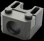
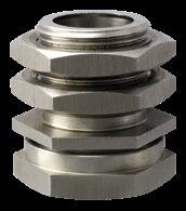


Detailed data sheets for these products can be found on the Contrinex website:94 CHALLENGES SOLUTIONS ACCESSORIES For extensive protection, use Activstone® coated mounting brackets, spatter-resistant cables and protective tubes. Uncoated brackets are also available. ANTI-SPATTER COATING Activstone® coating on all external surfaces resists weld spatter in spot, MIG and MAG applications. IMPACT RESISTANCE With one-piece stainless-steel housings and Condet® technology, Full Inox sensors offer maximum impact resistance. WELD-FIELD IMMUNITY Contrinex sensors resist magnetic interference from medium-frequency weld fields, current up to 15 kA. WELD SPATTER • Reduced sensor performance • Spatter accumulation • Difficulty replacing sensors MAGNETIC FIELDS • Interference with inductive sensor • False triggering • Sensor output locking on MOVING PARTS • Mechanical impact with moving workpieces • Damage to ferrite, electronics and housing • Frequent machine downtime


95WWW.CONTRINEX.COM FULL INOX (SERIES 700) CLASSICS (SERIES 600) FULL INOX HOUSING + DOUBLE OPERATING DISTANCE PLASTIC FACE + NORMAL OPERATING DISTANCE COATED UNCOATED COATED UNCOATED KEY FEATURES resistanceWeld-spatter 9 9 immunityMagnetic-field 9 9 9 9 Impact resistance 9 9 Long distanceoperating 9 9 Factor 1 on steel and aluminum 9 9 SIZE M8 9 9 9 9 M12 9 9 9 9 M18 9 9 9 9 M30 9 9 C23 9 CONNECTIVITY Connector M12, 4-pin 9 9 9 9 Pigtail M12, 3-pin 9 9 RATINGENCLOSURE IP67 9 9 9 9 IP68 9 9 IP69K 9 9 HOUSING Embeddable 9 9 9 9 One-piece stainless steel housing 9 9 Stainless steel housing and plastic sensing face 9 9 SENSOR SELECTOR


96 700SERIES–INOXFULL700SERIES–INOXFULLFAMILYCOATEDUNCOATED INDUCTIVE SENSORS WELD-IMMUNE Supply Voltage range 10 30 VDC COMMON FEATURES OPERATING DISTANCE (mm) HOUSINGSIZE(mm) HOUSINGLENGTH(mm) MATERIALHOUSING Go to pages 100 and 101 for details ACCESSORIESOUTPUT DW-A[x]-70[x] Connection [D] Cable [S] Connector [V] Pigtail Output [1] NPN NO [2] NPN NC [3] PNP NO [4] PNP NC Reference key on page 116 We made these pages with care, but we decline liability for any errors or omissions. M8 60 Stainless steel V2A M8 45 Stainless steel V2A M8 45 Stainless steel V2A 32 × 20 (C23) 8 Stainless steel V2A 32 × 20 (C23) 8 Stainless steel V2A M12 60 Stainless steel V2A M12 50 Stainless steel V2A M12 45 Stainless steel V2A M18 63.5 Stainless steel V2A M18 50 Stainless steel V2A M18 50 Stainless steel V2A M30 63.5 Stainless steel V2A M30 63.5 Stainless steel V2A M30 63.5 Stainless steel V2A M8 60 Stainless steel V2A M8 45 Stainless steel V2A M8 45 Stainless steel V2A M12 60 Stainless steel V2A M12 50 Stainless steel V2A M12 50 Stainless steel V2A M18 63.5 Stainless steel V2A M18 50 Stainless steel V2A M18 50 Stainless steel V2A M30 63.5 Stainless steel V2A M30 63.5 Stainless steel V2A M30 63.5 Stainless steel V2A


Detailed data sheets for these products can be found on the Contrinex website: 97WWW.CONTRINEX.COM WELD- IMMUNE CABLE CONNECTOR FREQUENCYSWITCHING(Hz) MOUNTING TEMPERATUREAMBIENT DEGREE PROTECTIONOF PART REFERENCEEMB. NON-EMB. VIEW DATASHEETSINDUCTIVE www.contrinex.com/collections/inductive-weld-immune 15 Embed. −25 +85°C IP68 / IP69K DW-AS-703-M8-697 0.2 m PUR 15 Embed. −25 +85°C IP68 / IP69K DW-AV-701-M8-696 0.2 m PUR 15 Embed. −25 +85°C IP68 / IP69K DW-AV-703-M8-696 0.2 m PUR 15 Embed. −25 +85°C IP68 / IP69K DW-AV-703-C23-696 0.2 m PUR 15 Embed. −25 +85°C IP68 / IP69K DW-AV-701-C23-696 15 Embed. −25 +85°C IP68 / IP69K DW-AS-703-M12-697 0.2 m PUR 15 Embed. −25 +85°C IP68 / IP69K DW-AV-701-M12-696 0.2 m PUR 15 Embed. −25 +85°C IP68 / IP69K DW-AV-703-M12-696 15 Embed. −25 +85°C IP68 / IP69K DW-AS-703-M18-697 0.2 m PUR 15 Embed. −25 … +85°C IP68 / IP69K DW-AV-701-M18-696 0.2 m PUR 15 Embed. −25 +85°C IP68 / IP69K DW-AV-703-M18-696 15 Embed. −25 +85°C IP68 / IP69K DW-AS-703-M30-697 0.2 m PUR 15 Embed. −25 +85°C IP68 / IP69K DW-AV-703-M30-696 0.2 m PUR 15 Embed. −25 +85°C IP68 / IP69K DW-AV-701-M30-696 15 Embed. −25 +85°C IP68 / IP69K DW-AS-703-M8-694 0.2 m PUR 15 Embed. −25 +85°C IP68 / IP69K DW-AV-701-M8-695 0.2 m PUR 15 Embed. −25 +85°C IP68 / IP69K DW-AV-703-M8-695 15 Embed. −25 +85°C IP68 / IP69K DW-AS-703-M12-673 0.2 m PUR 15 Embed. −25 +85°C IP68 / IP69K DW-AV-701-M12-692 0.2 m PUR 15 Embed. −25 +85°C IP68 / IP69K DW-AV-703-M12-695 15 Embed. −25 +85°C IP68 / IP69K DW-AS-703-M18-673 0.2 m PUR 15 Embed. −25 +85°C IP68 / IP69K DW-AV-701-M18-692 0.2 m PUR 15 Embed. −25 +85°C IP68 / IP69K DW-AV-703-M18-695 15 Embed. −25 +85°C IP68 / IP69K DW-AS-703-M30-673 0.2 m PUR 15 Embed. −25 +85°C IP68 / IP69K DW-AV-703-M30-695 0.2 m PUR 15 Embed. −25 … +85°C IP68 / IP69K DW-AV-701-M30-695
98 600SERIES–CLASSICS600SERIES–CLASSICSFAMILYCOATEDUNCOATED OPERATING DISTANCE (mm) HOUSINGSIZE(mm) HOUSINGLENGTH(mm) MATERIALHOUSING INDUCTIVE SENSORS WELD-IMMUNE Supply Voltage range 10 30 VDC COMMON FEATURES Go to pages 100 and 101 for details OUTPUTACCESSORIES DW-A[x]-62[x] Connection [D] Cable [S] Connector [V] Pigtail Output [1] NPN NO [2] NPN NC [3] PNP NO [4] PNP NC Reference key on page 116 We made these pages with care, but we decline liability for any errors or omissions. M8 66 Stainless steel V2A M12 60 Stainless steel V2A M18 63.5 Stainless steel V2A M8 66 Stainless steel V2A M12 60 Stainless steel V2A M18 63.5 Stainless steel V2A


Detailed data sheets for these products can be found on the Contrinex website: 99WWW.CONTRINEX.COM CABLE CONNECTOR FREQUENCYSWITCHING(Hz) MOUNTING TEMPERATUREAMBIENT DEGREE PROTECTIONOF PART REFERENCEEMB. NON-EMB. VIEW DATASHEETSINDUCTIVE www.contrinex.com/collections/inductive-weld-immune WELD- IMMUNE 15 Embed. −25 +70°C IP67 DW-AS-623-M8-697 15 Embed. −25 +70°C IP67 DW-AS-623-M12-697 15 Embed. −25 +70°C IP67 DW-AS-623-M18-697 15 Embed. −25 … +70°C IP67 DW-AS-623-M8-694 15 Embed. −25 +70°C IP67 DW-AS-623-M12-694 15 Embed. −25 +70°C IP67 DW-AS-623-M18-694

100 ACCESSORIES WELD-IMMUNE We made these pages with care, but we decline liability for any errors or omissions. REFERENCEPART MATERIAL DIMENSIONS(mm) COMPATIBLE WITH SENSOR SIZE CLASSICSSERIES600 FULLSERIESINOX700M8 M12 M18 M30 COATED ASU-0041-120 Steel L = 38.1 W = 34.9 H = 19.05 9 9 9 ASU-0041-180 Steel L = 38.1 W = 38.1 H = 25.4 9 9 9 ASU-0041-300 Steel L = 44.45 W = 59.94 H = 38.1 9 9 9 UNCOATED ASU-3012-080 Stainlesssteel SW17 L = 32.4 9 9 ASU-3012-120 Stainlesssteel SW22 L = 33.8 9 9 ASU-3012-180 Stainlesssteel SW30 L = 33.8 9 9 Reduce downtime with accessories that protect the surrounding installation against the challenges of welding environments. Mounting brackets with ACTIVSTONE® coating resist accumulation of weld spatter and so reduce the need for cleaning. A special range of stainless-steel mounting brackets offers exceptionally high mechanical and chemical resistance. For optimal protection use the long-life cables in spatter-resistant PUR and the high-temperature, spatter-resistant protective tubes to enhance machine availability. PROTECTION BEYOND THE SENSOR WELD-IMMUNE MOUNTING BRACKETS


Detailed data sheets for these products can be found on the Contrinex website: 101WWW.CONTRINEX.COM VIEW DATASHEETSINDUCTIVE www.contrinex.com/collections/accessories WELD- IMMUNE PART REFERENCE SOCKET CABLE SIZE PINS CONFIG. MATERIAL LENGTH S12-3FUG-020-NNWN M12 3 straight PUR 2 m S12-3FUG-050-NNWN M12 3 straight PUR 5 m S12-3FUW-020-NNWN M12 3 right angle PUR 2 m S12-3FUW-050-NNWN M12 3 right angle PUR 5 m S12-3FUG-020-NNWN-12MG M12 3 straight PUR 2 m + M12 plug S12-3FUG-050-NNWN-12MG M12 3 straight PUR 5 m + M12 plug SPATTER-RESISTANT CONNECTING CABLES SPATTER-RESISTANT PROTECTIVE TUBES PART REFERENCE MATERIAL DIAMETERINNER DIAMETEROUTER LENGTH APT-0000-010 PTFE 3.5 mm 6 mm 1 m APT-0000-100 PTFE 3.5 mm 6 mm 10 m APT-0001-010 PTFE 6.5 mm 10 mm 1 m APT-0001-100 PTFE 6.5 mm 10 mm 10 m APT-0002-100 PTFE 13 mm 17.5 mm 10 m APT-0003-100 PTFE 19 mm 23.5 mm 10 m


Tools for machining metal parts Metal recycling equipment INDUSTRIES Automotive production and supply, machine tool APPLICATION Sensors with full-metal housing withstand aggressive fluids and hot metal chips in machine tools Chip-Immune sensors on machine tools control the position of automatically fed workpieces as well as the workpiece clamping system. They are insensitive to dirt, heat, metal chips and dust. They also resist mechanical impacts, aggressive cutting oils, drilling emulsions and cleaning agents. Machine Automotivetoolsproduction and supply


Chip-Immune sensors prevent false switching due to metal debris in milling, drilling or grinding processes. Even when sensors are covered with metal chips, they reliably detect steel or aluminum objects. With one-piece stainlesssteel housings, an IP68/IP69K protection rating and operating temperatures from −25°C to +85°C (−13°F to +185°F), they are ideal for the harshest machining environments. PRODUCT ACCESSORIESOVERVIEW Go to page 298 to see all the accessories KEY ADVANTAGES 9 Detection not influenced by chips of steel, stainless steel, aluminum, brass, copper or titanium 9 Detection of targets made of the above metals 9 Robust, one-piece stainless-steel housing, protection rating IP68 and IP69K 9 Temperature range −25°C … +85°C (−13°F … +185°F) 9 Size M12, M18 and M30 9 Operating distances up to 12 mm 9 INDUCTIVE SENSORS FOR THE HARSHEST MACHINING ENVIRONMENTS Cables Mounting brackets Housing size mm M12 M18 M30 Full Inox (sn mm) 3 5 12 CHIP-IMMUNE


104 FAMILYFULLINOX–SERIES700 OPERATING DISTANCE (mm) HOUSINGSIZE(mm) HOUSINGLENGTH(mm) MATERIALHOUSING CABLES Cable lengths available: 2 m, 5 m, 10 m other customised lengths possible INDUCTIVE SENSORS CHIP-IMMUNE A Group A: M8 3-pin Sub-group: Field attachable connectors Sub-group: Distribution boxes B Group B: M8 4-pin C Group C: M12 4-pin Sub-group: Field attachable connectors Sub-group: Distribution boxes D Group D: M12 AC/DC 3-pin E Group E: Universal mounting brackets Sub-group: Mechanical stops F Group F: Photoelectric mounting brackets G Group G: Photoelectric reflectors H Group H: Sensor tester Go to page 298 for details ACCESSORIES Supply Voltage range 10 30 VDC ** Pigtail versions available COMMON FEATURES OUTPUT DW-A[x]-70[x] Connection [D] Cable [S] Connector [V] Pigtail Output [1] NPN NO [3] PNP NO Reference key on page 116 We made these pages with care, but we decline liability for any errors or omissions. M12 60 Stainless steel V2A M12 60 Stainless steel V2A M18 63.5 Stainless steel V2A M18 63.5 Stainless steel V2A M30 63.5 Stainless steel V2A M30 63.5 Stainless steel V2A


Detailed data sheets for these products can be found on the Contrinex website: 105WWW.CONTRINEX.COM CABLE ** CONNECTOR ** FREQUENCYSWITCHING(Hz) MOUNTING TEMPERATUREAMBIENT DEGREE PROTECTIONOF PART REFERENCE (SEEACCESSORIESPAGE104)EMB. NON-EMB.VIEW DATASHEETSINDUCTIVE www.contrinex.com/collections/inductive-chip-immune CHIP-IMMUNE 400 Non-embed. −25 +85°C IP68 / IP69K DW-AS-711-M12-967 CEH 400 Non-embed. −25 +85°C IP68 / IP69K DW-AS-713-M12-967 CEH 200 Non-embed. −25 +85°C IP68 / IP69K DW-AS-711-M18-967 CEH 200 Non-embed. −25 +85°C IP68 / IP69K DW-AS-713-M18-967 CEH 90 Non-embed. −25 +85°C IP68 / IP69K DW-AS-711-M30-967 CEH 90 Non-embed. −25 +85°C IP68 / IP69K DW-AS-713-M30-967 CEH
Robot handling of sheet metal Double-feed prevention for formed parts INDUSTRIES Automotive production and supply, machine tool, surface treatment, stamping and forming, aluminum industry APPLICATION Double-sheet sensing for deep-drawing press A producer of deep-drawn metal parts for the automo tive industry uses double-sheet sensing to prevent costly tool damage and downtime. An inductive sensor checks sheet metal as it is presented to the forming press. If it detects that two or more sheets have stuck together, the machine control system rejects the material and pre vents the press from operating. Aluminum Automotiveindustryproduction and supply


For double-sheet detection, sensors from the Full Inox family are used. Its inductive technology enables discrimination between one and two conductive metal sheets of a defined thickness, achieving sensitivity of 0.8–1.2 mm per sheet. This discrimination aids in the prevention of double feeds into blanking and forming processes which ultimately saves damage to tooling. PRODUCT ACCESSORIESOVERVIEW KEY ADVANTAGES 9 Double-sheet detection (steel and aluminum) with sensitivity of 0.8–1.2 mm per sheet 9 Full Inox: extremely robust one-piece stainless-steel housing 9 Corrosion resistant 9 IP68 and IP69K 9 Pressure resistant up to 80 bar INDUCTIVE SENSORS DOUBLE-SHEET DETECTION IN DOUBLE-SHEETMETALWORKINGOPERATINGDISTANCE(mm)HOUSINGSIZE(mm)HOUSINGLENGTH(mm)HOUSINGMATERIALCONNECTORSWITCHINGFREQUENCY(Hz) MOUNTING AMBIENTTEMP. DEGREE PROTECTIONOF 4 M30 63.5 steelStainlessV2A 10 Non-embed. −25 +85°C IP68 / IP69K C Group C: M12 4-pin Sub-group: Field attachable connectors Sub-group: Distribution boxes E Group E: Universal mounting brackets Sub-group: Mechanical stops H Group H: Sensor tester Go to page 298 for details PART700SERIES REFERENCE: DW-AS-713-M30-618


Wear monitoring, propeller shaft Machinery spaces in ships INDUSTRIES Maritime, machine tool, energy, vehicles, ships, port and offshore installations APPLICATION Rugged inductive sensor measures rotation velocity of wind turbine blades Modern wind turbines operate continuously in remote, highly demanding environments. Exceptional reliability is essential as opportunities for maintenance are limited. Turbine rotation velocity is a key operating parameter and manufacturers require robust sensor systems that provide accurate measurement in real-time. Rugged presence-sensing systems withstand harsh exposed conditions, both onshore and offshore, while delivering the required accuracy and reliability. Offshore installations Machine tools


The Maritime range of embeddable inductive sensors, certified by DNV, offers unrivaled performance features based on Full Inox technology. With a one-piece housing in V4A /AISI 316L stainless steel and an enclosure rating of IP68/IP69K, they are not only impervious, but also corrosion-proof and resistant to salt water. Their EMC protection also meets specific maritime requirements. PRODUCT ACCESSORIESOVERVIEW Go to page 298 to see all the accessories KEY ADVANTAGES 9 GL approved, class DNV-GL-CG-0339 9 Extremely rugged sensors, fit for Industry 4.0 9 Special EMC protection 9 Resistant to corrosion and salt water 9 Impervious, enclosure rating IP68 or IP69K 9 Temperature range −25 +85°C (−13 +185°F) 9 Full Inox types: one-piece stainless-steel housing (V4A / AISI 316L), factor 1 on steel and aluminum 9 Pressure-resistance available up to 500 bar (800 bar peak) 9 interface INDUCTIVE SENSORS FOR SHIPS, PORTS AND OFFSHORE Cables Mounting brackets Housing size mm M10 M12 M18 M30 P12G C23 snmm Classics 0.6 Full Inox 6 10 20 1.5 7 MARITIME TYPEAPPROVEDPRODUCT DNV.COM/AF


110 CLASSICSFAMILYSERIES600FULLINOX–SERIES700 OPERATING DISTANCE (mm) HOUSINGSIZE(mm) HOUSINGLENGTH(mm) MATERIALHOUSING INDUCTIVE SENSORS MARITIME CABLES Cable lengths available: 2 m, 5 m, 10 m other customised lengths possible A Group A: M8 3-pin Sub-group: Field attachable connectors Sub-group: Distribution boxes B Group B: M8 4-pin C Group C: M12 4-pin Sub-group: Field attachable connectors Sub-group: Distribution boxes D Group D: M12 AC/DC 3-pin E Group E: Universal mounting brackets Sub-group: Mechanical stops F Group F: Photoelectric mounting brackets G Group G: Photoelectric reflectors H Group H: Sensor tester Go to page 298 for details ACCESSORIES Supply Voltage range 10 30 VDC Output PNP NO COMMON FEATURES We made these pages with care, but we decline liability for any errors or omissions. OUTPUT DW-[x][x]-[x]0[x] Connection [D] Cable [S] Connector [V] Pigtail Output [1] NPN NO [2] NPN NC [3] PNP NO [4] PNP NC Technology Family [6] Classics [7] Full Inox Reference key on page 116 Sensor type [A] Conventional [M] Maritime M10 35 Stainless steel V2A M10 35 Stainless steel V2A M12 61 Stainless steel V4A M12 57.3 Stainless steel V4A M12 60 Stainless steel V4A M12 66.5 Stainless steel V4A M18 63.5 Stainless steel V4A M18 66.5 Stainless steel V4A M30 63.5 Stainless steel V4A M30 66.5 Stainless steel V4A 32 × 20 (C23) 8 Stainless steel V4A 32 × 20 (C23) 8 Stainless steel V4A


Detailed data sheets for these products can be found on the Contrinex website: 111WWW.CONTRINEX.COM CABLE CONNECTOR FREQUENCYSWITCHING(Hz) MOUNTING TEMPERATUREAMBIENT DEGREE PROTECTIONOF PART REFERENCE (SEEACCESSORIESPAGE110)EMB. NON-EMB.VIEW DATASHEETSINDUCTIVE www.contrinex.com/collections/inductive-maritime MARITIME PUR 2,500 Embed. −25 +70°C IP68 DW-AD-603-M10E-620 H PUR 2,500 Embed. −25 +70°C IP68 DW-AD-603-M10E-637 H 850 Embed. −25 +85°C IP68 / IP69K DW-MS-703-P12G CH PUR 850 Embed. −25 +85°C IP68 / IP69K DW-MD-703-P12G CH 600 Embed. −25 +85°C IP68 / IP69K DW-MS-703-M12 CEH PUR 600 Embed. −25 +85°C IP68 / IP69K DW-MD-703-M12 EH 300 Embed. −25 +85°C IP68 / IP69K DW-MS-703-M18-002 CEH PUR 300 Embed. −25 +85°C IP68 / IP69K DW-MD-703-M18 EH 100 Embed. −25 +85°C IP68 / IP69K DW-MS-703-M30-002 CEH PUR 100 Embed. −25 +85°C IP68 / IP69K DW-MD-703-M30 EH PVC 180 Embed. −25 +85°C IP68 / IP69K DW-MD-703-C23 H PVC 180 Embed. −25 … +85°C IP68 / IP69K DW-MV-703-C23-276 AH

APPLICATION
Sorting conveyor for egg packaging Brewery production equipment
INDUSTRIES Food and beverage, packaging, logistics, materials handling, pharmaceutical industry, industrial cleaning systems
Automated
Washdown inductive sensors monitor position of control valves during dairy-product processing During manufacture of dairy products, raw milk travels between successive processes through stainless-steel pipework. Rotary-shaft control valves maintain process sequences correctly, ensuring that no cross-contamina tion occurs during CIP cleaning after each batch is com pleted. Robust washdown inductive sensors, mounted on existing rotary actuators, monitor control-valve status around the clock, providing real-time positional feed back to a plant-wide control system in a simple, costeffective manner. laundry system Pharmaceutical industry


Washdown inductive sensors are certified to operate continuously and reliably in the harsh conditions of the food, beverage and pharmaceutical industries, ensuring uninterrupted production. Rated to IP68 and IP69K, they are pressure resistant up to 80 bar, food safe and corrosion resistant; additionally Full Inox – Series 700 are Ecolab certified. PRODUCT ACCESSORIESOVERVIEW Go to page 298 to see all the accessories KEY ADVANTAGES 9 Corrosion resistant 9 Food safe 9 IP68/IP69K protection 9 interface 9 Extremely rugged Full Inox types: one-piece stainless-steel housing, factor 1 on steel and aluminum 9 Ecolab approved INDUCTIVE WASHDOWNSENSORSECOLABAPPROVEDFORHARSHESTCLEANINGPROCESSES Cables Mounting brackets Housing size mm M12 M18 M30 snmm Classics 2 Full Inox 6 10 10 20 20 40


114 CLASSICSFAMILYSERIES600FULLINOX–SERIES700 OPERATING DISTANCE (mm) HOUSINGSIZE(mm) HOUSINGLENGTH(mm) MATERIALHOUSING INDUCTIVE SENSORS WASHDOWN CABLES Cable lengths available: 2 m, 5 m, 10 m other customised lengths possible A Group A: M8 3-pin Sub-group: Field attachable connectors Sub-group: Distribution boxes B Group B: M8 4-pin C Group C: M12 4-pin Sub-group: Field attachable connectors Sub-group: Distribution boxes D Group D: M12 AC/DC 3-pin E Group E: Universal mounting brackets Sub-group: Mechanical stops F Group F: Photoelectric mounting brackets G Group G: Photoelectric reflectors H Group H: Sensor tester Go to page 298 for details ACCESSORIES Supply Voltage range 10 30 VDC Output PNP NO* * Other types available: PNP NC, NPN NC COMMON FEATURES OUTPUT DW-L[x]-[x]0[x] Connection [D] Cable [S] Connector [V] Pigtail Output [1] NPN NO [2] NPN NC [3] PNP NO [4] PNP NC Technology Family [6] Classics [7] Full Inox Reference key on page 116 We made these pages with care, but we decline liability for any errors or omissions. M12 60 Stainless steel V4A M12 60 Stainless steel V4A M12 60 Stainless steel V4A M12 66.5 Stainless steel V4A M12 66.5 Stainless steel V4A M18 63.5 Stainless steel V4A M18 63.5 Stainless steel V4A M18 66.5 Stainless steel V4A M18 66.5 Stainless steel V4A M30 63.5 Stainless steel V4A M30 63.5 Stainless steel V4A M30 66.5 Stainless steel V4A M30 66.5 Stainless steel V4A M30 66.5 Stainless steel V4A


Detailed data sheets for these products can be found on the Contrinex website: 115WWW.CONTRINEX.COM CABLE CONNECTOR FREQUENCYSWITCHING(Hz) MOUNTING TEMPERATUREAMBIENT DEGREE PROTECTIONOF PART REFERENCE* (SEEACCESSORIESPAGE114)EMB. NON-EMB.VIEW DATASHEETSINDUCTIVE www.contrinex.com/collections/inductive-washdown WASHDOWN 1,700 Embed. −25 +120°C IP68 / IP69K DW-LS-603-M12 CEH 600 Embed. −25 +85°C IP68 / IP69K DW-LS-703-M12 CEH 400 Non-embed. −25 +85°C IP68 / IP69K DW-LS-713-M12 CEH Teflon 600 Embed. −25 +85°C IP68 / IP69K DW-LD-703-M12 EH Teflon 400 Non-embed. −25 +85°C IP68 / IP69K DW-LD-713-M12 EH 200 Embed. −25 +85°C IP68 / IP69K DW-LS-703-M18-002 CEH 200 Non-embed. −25 +85°C IP68 / IP69K DW-LS-713-M18-002 CEH Teflon 200 Embed. −25 +85°C IP68 / IP69K DW-LD-703-M18 EH Teflon 200 Non-embed. −25 +85°C IP68 / IP69K DW-LD-713-M18 EH 125 Embed. −25 +85°C IP68 / IP69K DW-LS-703-M30-002 CEH 90 Non-embed. −25 … +85°C IP68 / IP69K DW-LS-713-M30-002 CEH Teflon 125 Embed. −25 +85°C IP68 / IP69K DW-LD-703-M30 EH Teflon 90 Non-embed. −25 +85°C IP68 / IP69K DW-LD-713-M30 EH Teflon 100 Embed. −25 +85°C IP68 / IP69K DW-LD-703-M30-220 EH

Detailed data sheets for these products can be found on the Contrinex website:116 INDUCTIVE SENSORS REFERENCE KEY DW-AD-503-M8E (-12X/-XXX) SENSOR TYPE Conventional A 2-wire DC (NAMUR excepted) D High-temperature H Food and sea-water L Maritime M CONNECTION Cable D Connector S Cable + connector V INDUCTIVE SENSOR DW SERIES 500 / 520 (Extra Distance) 5 600 / 620 (Classics) 6 700 (Full Inox) 7 Embeddable / quasi-embeddable 0 Non-embeddable 1 Increased operating distance, (quasi-)embeddable 2 Increased operating distance, non-embeddable 3 OUTPUT NPN NO 1 NPN NC 2 PNP NO 3 PNP NC 4 PNP changeover A NPN changeover B SHORT / SPECIAL EXECUTIONS HOUSING SIZE Threaded cylindrical housing M Rectangular housing C Smooth cylindrical housing 0 High-pressure resistant P Series E (impervious) E Series 700P (all-metal and high-pressure resistant) G 2-wire AC/DC NO 7 NC 8 Analog 9 2-wire DC NO / NAMUR 5 NC 6 ThreadedHOUSINGOUTPUT M4 4 M5 5 M8 8 M12 12 M18 18 M30 30 M50 50 Smooth ∅ 3 mm 3 ∅ 4 mm 4 ∅ 6.5 mm 65 ∅ 8 mm 80 5 × 5 mm 5 8 × 8 mm 8 20 × 32 mm 23 40 × 40 mm 44
117WWW.CONTRINEX.COM VIEW DATASHEETSINDUCTIVE www.contrinex.com/collections/inductive-sensors REFERENCE KEY
Detailed data sheets for these products can be found on the Contrinex website:118

119SENSORSPHOTOELECTRICWWW.CONTRINEX.COMHIGHLIGHTS 9 Complete C23 series with first-class sensing ranges 9 Excellent background suppression sensors 9 Smallest self-contained miniature sensors on the market 9 Wide range of fiber-optic amplifiers, including 9 Excellent color and contrast recognition sensors NEW 9 C23 sensors with patented UV technology for transparent object detection, including 9 M18 series with short plastic housing and 9 Distance measurement sensors in C23 and C55 size with 9 Detection and measurement light grids 9 Fork sensors with

Detailed data sheets for these products can be found on the Contrinex website:120 PHOTOELECTRIC SENSORS PROGRAM OVERVIEW D04 M05 M12M 1120 M18P M18M 1180 ∅ 4 M5 M12 M12 M18 M18 M18 CYLINDRICAL FAMILY SERIES HOUSING SIZE IN MM OPERATINGPRINCIPLE SENSINGRANGE STANDARD Diffuse 0 … 1,500 mm suppressionBackground 2 5,000 mm Reflex 0 8,000 mm Through-beam 0 50,000 mm MINIATURE Diffuse 0 90 mm suppressionBackground 2 … 120 mm Reflex 0 3,000 mm Through-beam 0 2,000 mm TRANSPARENT OBJECT Reflex, UV light 0 1,200 mm Reflex, red light 10 5,000 mm OPTICFIBER ANDSENSORS FIBERS Amplifier 0 200 mm Plastic fiber 0 1,100 mm Glass fiber 0 500 mm DISTANCE Short range 20 200 mm Medium range 0 5,000 mm COLOR AND CONTRAST Color 30 40 mm Contrast 12 mm LIGHT GRIDS Detection 80 8,000 mm Measurement 300 4,000 mm FORK Through-beam 0 120 mm p. 126 p. 128 p. 130 p. 132 p. 134 p. 130 p. 132 p. 134 p. 126 p. 128 p. 130 p. 132 p. 134 p. 126 p. 128 p. 130 p. 132 p. 136 p. 150 p. 150 p. 150 p. 152
PROGRAM OVERVIEW 121WWW.CONTRINEX.COM VIEW DATASHEETSPHOTOELECTRIC www.contrinex.com/collections/photoelectric-sensors 0507 C12 C23 3030 3060 4050 C55 DGI MGI LG 5×7×40 1313×21×7×27×7 2020×30×10×34×12 30×30×15 31×60×10 40×50×15 50×50×23 40×20×H 40×20×H 60×10×GAP CUBIC U-SHAPE p. 138 p. 142 p. 144 p. 138 p. 142 p. 144 p. 146 p. 140 p. 142 p. 144 p. 140 p. 142 p. 144 p. 154 p. 156 p. 156 p. 156 p. 160 p. 160 p. 164 p. 166 p. 168 p. 166 p. 170 p. 178 p. 180 p. p.184184 p. 188 p. 190 p. 194
A reflex, or reflective, photoelectric sensor contains a transmitter and a receiver in a single housing, and emits a pulsed, focused light beam toward a distant reflector. Reflected light returns to the sensor, arriv ing at the receiver. When a target object interrupts the light beam, the receiver detects the reduced light intensity and triggers the sensor.
FAMILIESTECHNOLOGYDIFFUSE
SUPPRESSIONBACKGROUND
OPERATING PRINCIPLE
and surface finish, although sensor sensitivity is adjustable during installation to compensate for targets with poor reflective qualities.
Diffuse-mode sensors are cost-effective as they do not require separate reflectors or receivers, and detect reflective targets with ease. Sensing range depends on the target’s size, shape, color
REFLEX Long sensing range in a single-housing device
The relatively high level of reflected light allows reflex sensors to achieve sensing distances up to eight meters.
A through-beam photoelectric sensor comprises an emitter and receiver, each mounted in a separate housing. The emitter is aligned so that the greatest possible amount of pulsed light from its emitting diode reaches the receiver (Fig. 11). The receiver, which is mounted beyond the target area, processes incoming light in such a way that it is clearly sep arated from ambient and other light sources. Any interruption of the light beam by a target triggers the sensor, causing its output signal to switch.
Fig. 9: Diffuse sensing
Versatile and cost-effective
Contrinex through-beam photoelectric sensors are ideal for industrial applications where sensing com ponents must be mounted some distance from the target area. Through-beam sensors utilize infrared, Fig. 8: Functional blocks of a photoelectric sensor receiver amplifier shaperpulse outputstage short-circuitprotection emitter generatorpulse regulatorvoltage
BEAMTHROUGHEmitter and receiver in separate housings for sensing ranges from 0 to 50 m
Excellent suppression of light-colored backgrounds Diffuse-mode photoelectric sensors with back ground suppression emit a focused light beam toward a distant target. Part of the beam is reflected from the target and returns to the sensor, striking a position-sensitive receiver. The receiver distin guishes between reflections from the target and reflections from background objects, only trigger ing the sensor when the signal reaches a value that relates to the preset target distance. The sensing range is practically insensitive to the target’s size, color, shape and surface finish, and background-suppression sensors provide highly reliable detection of “difficult” targets, even against a light background. Stable, accurate detection of small, fast-moving parts on conveyors or auto mated machinery is possible over the entire sens ing range, eliminating false triggering by objects in the background.
A diffuse-mode, or energetic-diffuse, photoelectric sensor is a reflective sensor, containing a transmit ter and a receiver in a single housing. The sensor emits a light beam toward a distant target that acts as a reflector, returning part of the transmitted light to the sensor. The receiver detects the amount of light reflected by the target, triggering the sensor when the light intensity reaches a threshold value.
The light-emitting diode (LED) emits a beam of modulated light towards the target. This beam is inter rupted by the target, causing partial reflection. A part of the reflected light reaches the sensing face of the receiver. Depending on the operating principle, either the interrupted beam or the reflected light is used for further processing.
Detailed data sheets for these products can be found on the Contrinex website:122 PHOTOELECTRIC SENSORS
Fig. 10: Reflex sensing Fig. 11: Through-beam sensing
Precise distance control Photoelectric sensors with analog outputs are ideal for measuring absolute values of distance. Using background suppression-mode technology, analog photoelectric sensors produce an output signal that is accurately calibrated and approximately proportional to the distance of the target from the sensor. Users have a choice of current or voltage outputs that are compatible with all modern control systems.
ANALOG OUTPUT
visible and laser light sources to detect opaque and semi-transparent targets, reliably and repeatably, at extended distances.
The Contrinex TRU-C23 pho toelectric sensor is ideally suited for the presence con trol of transparent objects. Its patented technology uses UV light. Since transparent mate rials like plastic or glass absorb large amounts of polarized UV light, it is very easy to set the threshold at which the sensor switches. The shape or thickness of the target has no influence on detection. In addition, sensor performance is unaffected by dirt, water drops or aging.
OBJECTTRANSPARENT
PRODUCT RANGES
Outstanding reliability and ease of environmentsadjustment
The use of infrared light grids for non-contact measurement offers many advantages, includ ing fast response times, reliable detection of the most varied objects and immunity to inter ference from ambient light. Typ ical applications can be found in logistics, automated packaging systems, warehouses and the wood industry.
MINIATURE Smallest on the market
Color photoelectric sensors utilize energetic-diffuse sens ing technology to detect vari ations in target color, allowing color sorting or color control. A “teach-in” function is used to program up to three separate outputs. Contrinex color photoelectric sensors also feature five select able tolerance levels for each output. Contrast sensors are ideal for detecting print marks in printing, labelling and packaging processes. Using a narrowly focused light beam and RGB emission technology, contrast sensors automat ically select the best emission color (red, green or blue) during the teach-in procedure.
The Contrinex Miniature range packs exceptional posi tion- and sorsthrough-beamDesignerstricself-containedperformancepresence-sensingintothesmallestphotoelecsensorsonthemarket.havethechoiceofordiffusesenin ∅ 4 and M5 cylindri cal metal housings that offer multiple mounting methods and beam orientation. For fully embedded applications, sensors with spherical sapphire-glass lenses produce focused, cylindrical light beams. The highly versatile FiberOptic range includes the self-contained 3030 series and the DIN-rail mounted 3060 series, suitable for multiple-sensor applications. Synthetic fibers are available for general use and glass fibers for high temperatures and aggressive environments.
ANDSENSORSFIBER-OPTICFIBERS
123WWW.CONTRINEX.COM
Reliable short and longrange sensing LIGHT GRIDS Fast detection, counting and measurement COLOR CONTRASTAND Excellent resolution for smallest variations
DISTANCE High precision and direct digital DTR-C23transmission and DTL-C23 sensors use a triangulation method for highly accurate distance measurement at short range. Types with red light (DTR-C23) measure dis tances up to 200 mm, while the measurement range for laser types (DTL-C23) is up to 100 mm. Applications include small-part detection, position or height checking and monitoring material thickness on winding rolls.
FORK Fast detection and counting in one housing Fork sensors come either with an infrared or red LED with a detection frequency up to 14 kHz. They operate like a through beam sensor with the advantage of having the sensing and receiving element included in the same housing, thus reducing efforts on align ment and cable assembly. Fork sensors are particularly useful in packaging appli cation to detect and count high speed objects or check the presence of a cap, hood or cover.
STANDARD First-class performance for general use Contrinex Standard photoelec tric sensors are ideal for gen eral position- and presence-de tection in almost any industry. With first-class sensing ranges and outstanding background suppression characteristics, the Standard range of sensors delivers very high accuracy and reliability. Light sources include infrared, laser and pinpoint LED.


Beverage filling machines
Conveyor systems
Miniature photoelectric sensor detects fill level during secondary packaging operations During secondary packaging of bags of confectionery, manufacturers arrange bags in overlapping layers. Multi-axis pick-and-place packing robots align and pack layers of bags in preformed cardboard cartons. The filled cartons are conveyed to case-sealing stations. A highly reliable photoelectric sensor, mounted directly above the conveyor, senses the height of the top layer of bags in each carton before sealing and rejects insuffi ciently filled cartons. Rugged photoelectric sensors with background suppression from the Contrinex C23 range are ideal for this application. A pinpoint red LED with a 10 mm-diameter light spot at the maximum sensing range of 300 mm ensures highly reliable detection of objects of almost any color against light or dark back grounds. These sensors are well suited to both the task and the environment.
Textile spinning machine automation
Automotive production and supply, machine tool, packaging, logistics, materials handling, food and beverage, textile Automotive part sensing
APPLICATION
INDUSTRIES


STANDARDSENSORSPHOTOELECTRICFIRST-CLASSPERFORMANCEFOR GENERAL USE Contrinex Standard photoelectric sensors are ideal for general position- and presence-detection in almost any industry. With first-class sensing ranges and outstanding background pinpointsourceshighrangecharacteristics,suppressiontheStandardofsensorsdeliversveryaccuracyandreliability.Lightincludeinfrared,laserandLED. PRODUCT ACCESSORIESOVERVIEW Go to page 298 to see all the accessories KEY ADVANTAGES 9 First-class sensing ranges 9 Outstanding background suppression characteristics 9 C23 and M18P series: high quality ASIC sensors with an integral interface in PNP types 9 Light sources: red, infrared, laser and pinpoint LED C23 Series 9 Excellent background suppression characteristics with pin point LED 9 Mutual interference immunity 9 Versions available with stability alarm as second output 9 Enclosure rating IP67, Ecolab approved M18P Series 9 Short housing: 37 mm with connector (cable types 33 mm) 9 Excellent background suppression characteristics with pin point LED 9 Mutual interference immunity 9 Easy flush mounting 9 Easy-to-mount special accessories for right-angle emission SERIES Housing size mm M12M M12 1120 M12 M18P M18 M18M M18 1180 M18 C23 20×30×10 3030 30×30×15 4050 40×50×15 C55 50×50×23 snmm Diffuse 800 300 1,200 1,200 250 / 600 1,500 600 / 1,200 1,200 Reflex 4,000 1,500 7,000 7,000 2,000 8,000 2,000 / 4,000 4,000 Through-beam 10,000 10,000 / 50,000 30,000 30,000 20,000 / 50,000 30,000 6,000 / 12,000 50,000 Background suppression 250 250 120 300 200 500 5,000 Mounting bracketsCablesReflectors


PHOTOELECTRIC SENSORS STANDARD CABLES Cable lengths available: 2 m, 5 m, 10 m other customised lengths possible A Group A: M8 3-pin Sub-group: Field attachable connectors Sub-group: Distribution boxes B Group B: M8 4-pin Sub-group: Field attachable connectors C Group C: M12 4-pin Sub-group: Field attachable connectors Sub-group: Distribution boxes D Group D: M12 AC/DC 3-pin E Group E: Universal mounting brackets Sub-group: Mechanical stops F Group F: Photoelectric mounting brackets G Group G: Photoelectric reflectors H Group H: Sensor tester Go to page 298 for details ACCESSORIES OPERATINGPRINCIPLE SENSING RANGE (mm) HOUSINGSIZE(mm) LIGHT SOURCEFAMILYCYLINDRICALM12–M12MSERIESCYLINDRICAL M12 M12M SERIES Supply Voltage range 10 30 VDC COMMON FEATURES 126 Diffuse Reflex Through-beam OPERATING PRINCIPLE OUTPUT [xx][x]-M12MA-[xxx]-[xxx] see p. 196 Sensor type [LL] Through-beam [LR] Reflex [LT] Diffuse see p. 196Emission type [R] Red Reference key on page 196 We made these pages with care, but we decline liability for any errors or omissions. 800 M12 LED, red 645 nm 800 M12 LED, red 645 nm 800 M12 LED, red 645 nm 800 M12 LED, red 645 nm 4,000 M12 LED, red 645 nm 4,000 M12 LED, red 645 nm 4,000 M12 LED, red 645 nm 4,000 M12 LED, red 645 nm 10,000 M12 LED, red 630 nm 10,000 M12 LED, red 630 nm 10,000 M12 LED, red 630 nm 10,000 M12 LED, red 630 nm 10,000 M12 LED, red 630 nm 10,000 M12 LED, red 630 nm


MATERIALHOUSING CABLE CONNECTOR FREQUENCYSWITCHING(Hz) TEMPERATUREAMBIENT PROTECTIONDEGREEOF PART REFERENCE (SEEACCESSORIESPAGE126) KEY ADVANTAGES 9 M12 metal housing 9 Sensitivity adjustment via potentiometer or 9 Focused RED light source 9 Calibrated range 9 Immune to mutual interference 9 v1.0 SERIESM12M CYLINDRICAL M12 Detailed data sheets for these products can be found on the Contrinex website: 127WWW.CONTRINEX.COM VIEW DATASHEETSPHOTOELECTRIC www.contrinex.com/collections/photoelectric-standard-m12-cylindrical Chrome-platedbrass 1,500 −25 … +65°C IP67 LTR-M12MA-PMS-603 CEGH Chrome-platedbrass 1,500 −25 +65°C IP67 LTR-M12MA-PMS-101 CEGH Chrome-platedbrass PVC 1,500 −25 +65°C IP67 LTR-M12MA-PMK-603 EH Chrome-platedbrass PVC 1,500 −25 +65°C IP67 LTR-M12MA-PMK-101 EH Chrome-platedbrass 1,500 −25 … +65°C IP67 LRR-M12MA-NMS-603 CEGH Chrome-platedbrass 1,500 −25 +65°C IP67 LRR-M12MA-NMS-101 CEGH Chrome-platedbrass PVC 1,500 −25 +65°C IP67 LRR-M12MA-NMK-603 EH Chrome-platedbrass PVC 1,500 −25 +65°C IP67 LRR-M12MA-NMK-101 EH Chrome-platedbrass 1,000 −25 +65°C IP67 LLR-M12MA-NMS-400 CEGH Chrome-platedbrass PVC 1,000 −25 +65°C IP67 LLR-M12MA-NMK-400 EH Chrome-platedbrass 1,000 −25 +65°C IP67 LLR-M12MA-NMS-603 CEGH Chrome-platedbrass 1,000 −25 +65°C IP67 LLR-M12MA-NMS-101 CEGH Chrome-platedbrass PVC 1,000 −25 +65°C IP67 LLR-M12MA-NMK-603 EH Chrome-platedbrass PVC 1,000 −25 … +65°C IP67 LLR-M12MA-NMK-101 EH

PHOTOELECTRIC SENSORS STANDARD CABLES Cable lengths available: 2 m, 5 m, 10 m other customised lengths possible A Group A: M8 3-pin Sub-group: Field attachable connectors Sub-group: Distribution boxes B Group B: M8 4-pin Sub-group: Field attachable connectors C Group C: M12 4-pin Sub-group: Field attachable connectors Sub-group: Distribution boxes D Group D: M12 AC/DC 3-pin E Group E: Universal mounting brackets Sub-group: Mechanical stops F Group F: Photoelectric mounting brackets G Group G: Photoelectric reflectors H Group H: Sensor tester Go to page 298 for details ACCESSORIES OPERATINGPRINCIPLE SENSING RANGE (mm) HOUSINGSIZE(mm) LIGHT SOURCEFAMILYCYLINDRICALM12–1120SERIESCYLINDRICAL M12 1120 SERIES Supply Voltage range 10 30 VDC Output PNP Light-ON* * Other types available: PNP, NPN, Light-ON/Dark-ON COMMON FEATURES 128 Diffuse Reflex Through-beam OPERATING PRINCIPLE OUTPUT L[x][x]-112[x][x]-[xxx] see p. 197 Sensor type [L] Through-beam [R] Reflex [T] Diffuse Connection [K] Cable [S] Connector [L] Laser [0] High performance [1] Standard Reference key on page 197 We made these pages with care, but we decline liability for any errors or omissions. 300 M12 LED, red 660 nm 300 M12 LED, red 660 nm 1,500 M12 LED, red 660 nm 1,500 M12 LED, red 660 nm 10,000 M12 LED, red 660 nm 10,000 M12 LED, red 660 nm 50,000 M12 Laser class 2, red 660 nm 50,000 M12 Laser class 2, red 660 nm


MATERIALHOUSING CABLE CONNECTOR FREQUENCYSWITCHING(Hz) TEMPERATUREAMBIENT PROTECTIONDEGREEOF PART REFERENCE * (SEEACCESSORIESPAGE128) KEY ADVANTAGES 9 M12 sensor series 9 Rugged metal housing 9 Shock and vibration resistant due to fully potted electronics 9 Laser types (protection class 2) for accurate detection of smallest targets 9 Sensing range up to 50 m SERIES1120 CYLINDRICAL M12 VIEW DATASHEETSPHOTOELECTRIC www.contrinex.com/collections/photoelectric-standard-m12-cylindrical Detailed data sheets for these products can be found on the Contrinex website: 129WWW.CONTRINEX.COM Chrome-platedbrass PVC 1,000 −25 … +55°C IP67 LTK-1120-303 EH Chrome-platedbrass 1,000 −25 +55°C IP67 LTS-1120-303 CEH Chrome-platedbrass PVC 1,000 −25 +55°C IP67 LRK-1120-303 EGH Chrome-platedbrass 1,000 −25 +55°C IP67 LRS-1120-303 CEGH Chrome-platedbrass PVC 1,000 −25 … +55°C IP67 LLK-1120-203 EH Chrome-platedbrass 1,000 −25 +55°C IP67 LLS-1120-203 CEH Stainless steel V2A PVC 5,000 −10 +50°C IP67 LLK-1121L-203 EH Stainless steel V2A 5,000 −10 +50°C IP67 LLS-1121L-203 CEH

PHOTOELECTRIC SENSORS STANDARD CABLES Cable lengths available: 2 m, 5 m, 10 m other customised lengths possible A Group A: M8 3-pin Sub-group: Field attachable connectors Sub-group: Distribution boxes B Group B: M8 4-pin Sub-group: Field attachable connectors C Group C: M12 4-pin Sub-group: Field attachable connectors Sub-group: Distribution boxes D Group D: M12 AC/DC 3-pin E Group E: Universal mounting brackets Sub-group: Mechanical stops F Group F: Photoelectric mounting brackets G Group G: Photoelectric reflectors H Group H: Sensor tester Go to page 298 for details ACCESSORIES OPERATINGPRINCIPLE SENSING RANGE (mm) HOUSINGSIZE(mm) LIGHT SOURCEFAMILYCYLINDRICALM18–M18P/M18MSERIESCYLINDRICALSERIESM18P/M18MM18Supply Voltage range 10 30 VDC Output PNP Light-ON* * Other types available: PNP, NPN, Dark-ON, Light-ON/ Dark-ON, Light-ON + stability alarm, Dark-ON + stability alarm COMMON FEATURES 130 Background suppression Diffuse Reflex Through-beam OPERATING PRINCIPLE OUTPUT [xx][x]-M18[x]A-[xxx]-[xxx] see p. 196 Sensor type [LT] Diffuse [LR] Reflex [LL] Through-beam [LH] Background suppression see p. 196Emission type [R] Red Housing material [M] Metal [P] Plastic Reference key on page 196 We made these pages with care, but we decline liability for any errors or omissions. 250 M18 Pinpoint LED, red 640 nm 250 M18 Pinpoint LED, red 640 nm 250 M18 Pinpoint LED, red 640 nm 250 M18 Pinpoint LED, red 640 nm 250 M18 Pinpoint LED, red 640 nm 250 M18 Pinpoint LED, red 640 nm 250 M18 Pinpoint LED, red 640 nm 250 M18 Pinpoint LED, red 640 nm 250 M18 Pinpoint LED, red 640 nm 250 M18 Pinpoint LED, red 640 nm 250 M18 Pinpoint LED, red 640 nm 250 M18 Pinpoint LED, red 640 nm 1,200 M18 LED, red 630 nm 1,200 M18 LED, red 630 nm 1,200 M18 LED, red 630 nm 1,200 M18 LED, red 630 nm 1,200 M18 LED, red 630 nm 1,200 M18 LED, red 630 nm 1,200 M18 LED, red 630 nm 1,200 M18 LED, red 630 nm 7,000 M18 LED, red 630 nm 7,000 M18 LED, red 630 nm 30,000 M18 LED, red 630 nm


MATERIALHOUSING CABLE CONNECTOR FREQUENCYSWITCHING(Hz) TEMPERATUREAMBIENT PROTECTIONDEGREEOF PART REFERENCE * (SEEACCESSORIESPAGE130) KEY ADVANTAGES 9 First-class sensing ranges 9 Short housing: M18 × 33 mm (cable version), M18 × 37 mm (connector version) 9 Excellent background suppression characteristics with pinpoint LED 9 Mutual interference immunity 9 on all PNP sensors 9 Easy flush mounting 9 Easy-to-mount special accessories for right-angle emission SERIESM18P/M CYLINDRICAL M18 VIEW DATASHEETSPHOTOELECTRIC www.contrinex.com/collections/photoelectric-standard-m18-cylindrical Detailed data sheets for these products can be found on the Contrinex website: 131WWW.CONTRINEX.COM ABS PVC 700 −25 … +65°C IP67 LHR-M18PA-PMK-403 FH ABS PVC 700 −25 +65°C IP67 LHR-M18PA-PMK-603 FH ABS PVC 700 −25 +65°C IP67 LHR-M18PA-PMK-60C FH ABS 700 −25 +65°C IP67 LHR-M18PA-PMS-403 CFH ABS 700 −25 … +65°C IP67 LHR-M18PA-PMS-603 CFH ABS 700 −25 +65°C IP67 LHR-M18PA-PMS-60C CFH ABS PVC 700 −25 +65°C IP67 LHR-M18PA-TMK-403 FH ABS PVC 700 −25 +65°C IP67 LHR-M18PA-TMK-603 FH ABS PVC 700 −25 +65°C IP67 LHR-M18PA-TMK-60C FH ABS 700 −25 +65°C IP67 LHR-M18PA-TMS-403 CFH ABS 700 −25 +65°C IP67 LHR-M18PA-TMS-603 CFH ABS 700 −25 +65°C IP67 LHR-M18PA-TMS-60C CFH ABS PVC 1,500 −25 +65°C IP67 LTR-M18PA-PMK-403 FH ABS PVC 1,500 −25 … +65°C IP67 LTR-M18PA-PMK-603 FH ABS PVC 1,500 −25 +65°C IP67 LTR-M18PA-PMK-60C FH ABS 1,500 −25 +65°C IP67 LTR-M18PA-PMS-403 CFH ABS 1,500 −25 +65°C IP67 LTR-M18PA-PMS-603 CFH ABS 1,500 −25 … +65°C IP67 LTR-M18PA-PMS-60C CFH ABS PVC 1,500 −25 +65°C IP67 LTR-M18PA-NMK-403 FH ABS 1,500 −25 +65°C IP67 LTR-M18PA-NMS-403 CFH ABS PVC 1,500 −25 +65°C IP67 LRR-M18PA-NMK-603 FGH ABS 1,500 −25 +65°C IP67 LRR-M18PA-NMS-603 CFGH ABS PVC 1,000 −25 +65°C IP67 LLR-M18PA-NMK-400 FH
PHOTOELECTRIC SENSORS STANDARD CABLES Cable lengths available: 2 m, 5 m, 10 m other customised lengths possible A Group A: M8 3-pin Sub-group: Field attachable connectors Sub-group: Distribution boxes B Group B: M8 4-pin Sub-group: Field attachable connectors C Group C: M12 4-pin Sub-group: Field attachable connectors Sub-group: Distribution boxes D Group D: M12 AC/DC 3-pin E Group E: Universal mounting brackets Sub-group: Mechanical stops F Group F: Photoelectric mounting brackets G Group G: Photoelectric reflectors H Group H: Sensor tester Go to page 298 for details ACCESSORIES OPERATINGPRINCIPLE SENSING RANGE (mm) HOUSINGSIZE(mm) LIGHT SOURCEFAMILYCYLINDRICALM18–M18P/M18MSERIESCYLINDRICALSERIESM18P/M18MM18Supply Voltage range 10 30 VDC Output PNP Light-ON* * Other types available: PNP, NPN, Dark-ON, Light-ON/ Dark-ON, Light-ON + stability alarm, Dark-ON + stability alarm COMMON FEATURES 132 Background suppression Diffuse Reflex Through-beam OPERATING PRINCIPLE OUTPUT [xx][x]-M18[x]A-[xxx]-[xxx] see p. 196 Sensor type [LT] Diffuse [LR] Reflex [LL] Through-beam [LH] Background suppression see p. 196Emission type [R] Red Housing material [M] Metal [P] Plastic Reference key on page 196 We made these pages with care, but we decline liability for any errors or omissions. 30,000 M18 LED, red 630 nm 30,000 M18 LED, red 630 nm 30,000 M18 LED, red 630 nm 250 M18 Pinpoint LED, red 640 nm 250 M18 Pinpoint LED, red 640 nm 1,200 M18 LED, red 630 nm 7,000 M18 LED, red 630 nm 30,000 M18 LED, red 630 nm 30,000 M18 LED, red 630 nm

MATERIALHOUSING CABLE CONNECTOR FREQUENCYSWITCHING(Hz) TEMPERATUREAMBIENT PROTECTIONDEGREEOF PART REFERENCE * (SEEACCESSORIESPAGE132) KEY ADVANTAGES 9 First-class sensing ranges 9 Short housing: M18 × 33 mm (cable version), M18 × 37 mm (connector version) 9 Excellent background suppression characteristics with pinpoint LED 9 Mutual interference immunity 9 on all PNP sensors 9 Easy flush mounting 9 Easy-to-mount special accessories for right-angle emission SERIESM18P/M CYLINDRICAL M18 VIEW DATASHEETSPHOTOELECTRIC www.contrinex.com/collections/photoelectric-standard-m18-cylindrical Detailed data sheets for these products can be found on the Contrinex website: 133WWW.CONTRINEX.COM ABS 1,000 −25 … +65°C IP67 LLR-M18PA-NMS-400 CFH ABS PVC 1,000 −25 +65°C IP67 LLR-M18PA-NMK-603 FH ABS 1,000 −25 +65°C IP67 LLR-M18PA-NMS-603 CFH Stainless steel 700 −25 +65°C IP67 LHR-M18MA-PMS-603 CFH Stainless steel 700 −25 … +65°C IP67 LHR-M18MA-TMS-603 CFH Stainless steel 1,500 −25 +65°C IP67 LTR-M18MA-PMS-603 CFH Stainless steel 1,500 −25 +65°C IP67 LRR-M18MA-NMS-603 CFGH Stainless steel 1,000 −25 +65°C IP67 LLR-M18MA-NMS-400 CFH Stainless steel 1,000 −25 +65°C IP67 LLR-M18MA-NMS-603 CFH

PHOTOELECTRIC SENSORS STANDARD CABLES Cable lengths available: 2 m, 5 m, 10 m other customised lengths possible A Group A: M8 3-pin Sub-group: Field attachable connectors Sub-group: Distribution boxes B Group B: M8 4-pin Sub-group: Field attachable connectors C Group C: M12 4-pin Sub-group: Field attachable connectors Sub-group: Distribution boxes D Group D: M12 AC/DC 3-pin E Group E: Universal mounting brackets Sub-group: Mechanical stops F Group F: Photoelectric mounting brackets G Group G: Photoelectric reflectors H Group H: Sensor tester Go to page 298 for details ACCESSORIES OPERATINGPRINCIPLE SENSING RANGE (mm) HOUSINGSIZE(mm) LIGHT SOURCEFAMILYCYLINDRICALM18–1180SERIESCYLINDRICAL M18 1180 SERIES Supply Voltage range 10 30 VDC Output PNP Light-ON* * Other types available: PNP, NPN, Light-ON/Dark-ON COMMON FEATURES 134 Background suppression Diffuse Reflex Through-beam OPERATING PRINCIPLE OUTPUT L[x][x]-118[x][x]-[xxx]-[xxx] see p. 197 Sensor type [H] Background suppression [L] Through-beam [R] Reflex [T] Diffuse Connection [K] Cable [S] Connector [L] Laser [W] Face 90° [0] High performance [1] Standard see p. 197 Reference key on page 197 We made these pages with care, but we decline liability for any errors or omissions. 120 M18 LED, red 660 nm 120 M18 LED, red 660 nm 120 M18 LED, red 660 nm 120 M18 LED, red 660 nm 250 M18 Laser class 2, red 660 nm 250 M18 Laser class 2, red 660 nm 250 M18 Laser class 2, red 660 nm 250 M18 Laser class 2, red 660 nm 600 M18 LED, red 660 nm 600 M18 LED, red 660 nm 600 M18 LED, red 660 nm 600 M18 LED, red 660 nm 600 M18 LED, red 660 nm 600 M18 LED, red 660 nm 600 M18 LED, red 660 nm 600 M18 LED, red 660 nm 600 M18 LED, red 660 nm 600 M18 Laser class 2, red 660 nm 600 M18 Laser class 2, red 660 nm 600 M18 Laser class 2, red 660 nm 600 M18 Laser class 2, red 660 nm 2,000 M18 LED, red 660 nm 2,000 M18 LED, red 660 nm

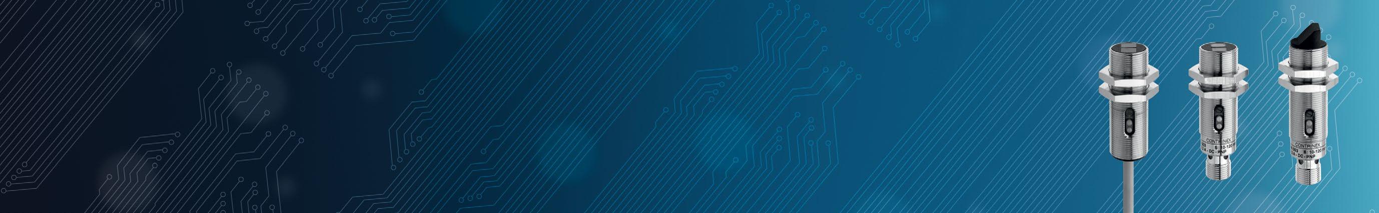
MATERIALHOUSING CABLE CONNECTOR FREQUENCYSWITCHING(Hz) TEMPERATUREAMBIENT PROTECTIONDEGREEOF PART REFERENCE * (SEEACCESSORIESPAGE134) KEY ADVANTAGES 9 Models for lateral sensing 9 Rugged metal housing 9 Shock & vibration resistant due to fully potted electronics 9 Laser types (protection class 2) for accurate detection of smallest targets 9 Sensing range up to 50 m SERIES1180 CYLINDRICAL M18 Detailed data sheets for these products can be found on the Contrinex website: 135WWW.CONTRINEX.COM VIEW DATASHEETSPHOTOELECTRIC www.contrinex.com/collections/photoelectric-standard-m18-cylindrical Chrome-platedbrass PVC 500 −25 … +55°C IP67 LHK-1180-303 EH Chrome-platedbrass 500 −25 +55°C IP67 LHS-1180-303 CEH Chrome-platedbrass PVC 500 −25 +55°C IP67 LHK-1180W-303 EH Chrome-platedbrass 500 −25 +55°C IP67 LHS-1180W-303 CEH Stainless steel V2A PVC 5,000 −10 … +50°C IP67 LTK-1180L-103-516 EH Stainless steel V2A PVC 5,000 −10 +50°C IP67 LTK-1180L-104-516 EH Stainless steel V2A 5,000 −10 +50°C IP67 LTS-1180L-103-516 CEH Stainless steel V2A 5,000 −10 +50°C IP67 LTS-1180L-104-516 CEH Chrome-platedbrass 1,000 −25 +55°C IP67 LTS-1180W-303 CEH Chrome-platedbrass PVC 1,000 −25 +55°C IP67 LTK-1180-103 EH Chrome-platedbrass PVC 1,000 −25 +55°C IP67 LTK-1180-104 EH Chrome-platedbrass 1,000 −25 +55°C IP67 LTS-1180-103 CEH Chrome-platedbrass 1,000 −25 +55°C IP67 LTS-1180-104 CEH Chrome-platedbrass PVC 1,000 −25 … +55°C IP67 LTK-1180W-103 EH Chrome-platedbrass PVC 1,000 −25 +55°C IP67 LTK-1180W-104 EH Chrome-platedbrass 1,000 −25 +55°C IP67 LTS-1180W-103 CEH Chrome-platedbrass 1,000 −25 +55°C IP67 LTS-1180W-104 CEH Stainless steel V2A PVC 1,000 −10 … +50°C IP67 LTK-1180L-103 EH Stainless steel V2A PVC 1,000 −10 +50°C IP67 LTK-1180L-104 EH Stainless steel V2A 1,000 −10 +50°C IP67 LTS-1180L-103 CEH Stainless steel V2A 1,000 −10 +50°C IP67 LTS-1180L-104 CEH Chrome-platedbrass PVC 1,000 −25 +55°C IP67 LRK-1180-303 EGH Chrome-platedbrass 1,000 −25 +55°C IP67 LRS-1180-303 CEGH
PHOTOELECTRIC SENSORS STANDARD CABLES Cable lengths available: 2 m, 5 m, 10 m other customised lengths possible A Group A: M8 3-pin Sub-group: Field attachable connectors Sub-group: Distribution boxes B Group B: M8 4-pin Sub-group: Field attachable connectors C Group C: M12 4-pin Sub-group: Field attachable connectors Sub-group: Distribution boxes D Group D: M12 AC/DC 3-pin E Group E: Universal mounting brackets Sub-group: Mechanical stops F Group F: Photoelectric mounting brackets G Group G: Photoelectric reflectors H Group H: Sensor tester Go to page 298 for details ACCESSORIES OPERATINGPRINCIPLE SENSING RANGE (mm) HOUSINGSIZE(mm) LIGHT SOURCEFAMILYCYLINDRICALM18–1180SERIESCYLINDRICAL M18 1180 SERIES Supply Voltage range 10 30 VDC Output PNP Light-ON* * Other types available: PNP, NPN, Light-ON/Dark-ON COMMON FEATURES 136 Background suppression Diffuse Reflex Through-beam OPERATING PRINCIPLE OUTPUT L[x][x]-118[x][x]-[xxx]-[xxx] see p. 197 Sensor type [H] Background suppression [L] Through-beam [R] Reflex [T] Diffuse Connection [K] Cable [S] Connector [L] Laser [W] Face 90° [0] High performance [1] Standard see p. 197 Reference key on page 197 We made these pages with care, but we decline liability for any errors or omissions. 2,000 M18 LED, red 660 nm 2,000 M18 LED, red 660 nm 20,000 M18 LED, red 660 nm 20,000 M18 LED, red 660 nm 20,000 M18 LED, red 660 nm 20,000 M18 LED, red 660 nm 20,000 M18 LED, red 660 nm 20,000 M18 LED, red 660 nm 20,000 M18 LED, red 660 nm 20,000 M18 LED, red 660 nm 50,000 M18 Laser class 2, red 660 nm 50,000 M18 Laser class 2, red 660 nm

MATERIALHOUSING CABLE CONNECTOR FREQUENCYSWITCHING(Hz) TEMPERATUREAMBIENT PROTECTIONDEGREEOF PART REFERENCE * (SEEACCESSORIESPAGE136) KEY ADVANTAGES 9 Models for lateral sensing 9 Rugged metal housing 9 Shock & vibration resistant due to fully potted electronics 9 Laser types (protection class 2) for accurate detection of smallest targets 9 Sensing range up to 50 m SERIES1180 CYLINDRICAL M18 Detailed data sheets for these products can be found on the Contrinex website: 137WWW.CONTRINEX.COM VIEW DATASHEETSPHOTOELECTRIC www.contrinex.com/collections/photoelectric-standard-m18-cylindrical Chrome-platedbrass PVC 1,000 −25 … +55°C IP67 LRK-1180W-303 EGH Chrome-platedbrass 1,000 −25 +55°C IP67 LRS-1180W-303 CEGH Chrome-platedbrass PVC 1,000 −25 +55°C IP67 LLK-1180W-003 EH Chrome-platedbrass PVC 1,000 −25 +55°C IP67 LLK-1180W-004 EH Chrome-platedbrass 1,000 −25 … +55°C IP67 LLS-1180W-003 CEH Chrome-platedbrass 1,000 −25 +55°C IP67 LLS-1180W-004 CEH Chrome-platedbrass PVC 1,000 −25 +55°C IP67 LLK-1180-003 EH Chrome-platedbrass PVC 1,000 −25 +55°C IP67 LLK-1180-004 EH Chrome-platedbrass 1,000 −25 +55°C IP67 LLS-1180-003 CEH Chrome-platedbrass 1,000 −25 +55°C IP67 LLS-1180-004 CEH Stainless steel V2A PVC 5,000 −10 +50°C IP67 LLK-1181L-003 EH Stainless steel V2A 5,000 −10 +50°C IP67 LLS-1181L-003 CEH

PHOTOELECTRIC SENSORS STANDARD CABLES Cable lengths available: 2 m, 5 m, 10 m other customised lengths possible A Group A: M8 3-pin Sub-group: Field attachable connectors Sub-group: Distribution boxes B Group B: M8 4-pin Sub-group: Field attachable connectors C Group C: M12 4-pin Sub-group: Field attachable connectors Sub-group: Distribution boxes D Group D: M12 AC/DC 3-pin E Group E: Universal mounting brackets Sub-group: Mechanical stops F Group F: Photoelectric mounting brackets G Group G: Photoelectric reflectors H Group H: Sensor tester Go to page 298 for details ACCESSORIES OPERATINGPRINCIPLE SENSING RANGE (mm) HOUSINGSIZE(mm) LIGHT SOURCEFAMILYCUBICC23–C23SERIESCUBICC23C23SERIESSupply Voltage range 10 30 VDC Output PNP Light-ON* * Other types available: PNP, NPN, Dark-ON, Light-ON/ Dark-ON, Light-ON + stability alarm, Dark-ON + stability alarm ** Pigtail versions available COMMON FEATURES 138 Background suppression Diffuse Reflex Through-beam OPERATING PRINCIPLE OUTPUT [xx][x]-C23PA-[xxx]-[xxx] see p. 196 Sensor type [LH] Background suppression [LL] Through-beam [LR] Reflex [LT] Diffuse see p. 196Emission type [R] Red Reference key on page 196 We made these pages with care, but we decline liability for any errors or omissions. 300 20 × 30 (C23) Pinpoint LED, red 640 nm 300 20 × 30 (C23) Pinpoint LED, red 640 nm 300 20 × 30 (C23) Pinpoint LED, red 640 nm 300 20 × 30 (C23) Pinpoint LED, red 640 nm 300 20 × 30 (C23) Pinpoint LED, red 640 nm 300 20 × 30 (C23) Pinpoint LED, red 640 nm 300 20 × 30 (C23) Pinpoint LED, red 640 nm 300 20 × 30 (C23) Pinpoint LED, red 640 nm 300 20 × 30 (C23) Pinpoint LED, red 640 nm 300 20 × 30 (C23) Pinpoint LED, red 640 nm 300 20 × 30 (C23) Pinpoint LED, red 640 nm 300 20 × 30 (C23) Pinpoint LED, red 640 nm 300 20 × 30 (C23) Pinpoint LED, red 640 nm 300 20 × 30 (C23) Pinpoint LED, red 640 nm 300 20 × 30 (C23) Pinpoint LED, red 640 nm 300 20 × 30 (C23) Pinpoint LED, red 640 nm 1,500 20 × 30 (C23) LED, red 630 nm 1,500 20 × 30 (C23) LED, red 630 nm 1,500 20 × 30 (C23) LED, red 630 nm 1,500 20 × 30 (C23) LED, red 630 nm 1,500 20 × 30 (C23) LED, red 630 nm 1,500 20 × 30 (C23) LED, red 630 nm 1,500 20 × 30 (C23) LED, red 630 nm

MATERIALHOUSING CABLE ** CONNECTOR** FREQUENCYSWITCHING(Hz) TEMPERATUREAMBIENT PROTECTIONDEGREEOF PART REFERENCE * (SEEACCESSORIESPAGE138) KEY ADVANTAGES 9 First-class sensing ranges 9 Small plastic housing, 20 × 30 × 10 mm 9 Excellent background suppression characteristics with pinpoint LED 9 interface available on PNP types 9 Mutual interference immunity 9 Versions available with stability alarm as second output 9 Enclosure rating IP67, Ecolab approved 9 Versatile mounting brackets for ease of installation SERIESC23 C23CUBICVIEW DATASHEETSPHOTOELECTRIC www.contrinex.com/collections/photoelectric-standard-c23-cubic Detailed data sheets for these products can be found on the Contrinex website: 139WWW.CONTRINEX.COM ABS PVC 1,000 −25 … +65°C IP67 LHR-C23PA-PMK-403 FH ABS PVC 1,000 −25 +65°C IP67 LHR-C23PA-PMK-603 FH ABS PVC 1,000 −25 +65°C IP67 LHR-C23PA-PMK-60C FH ABS 1,000 −25 +65°C IP67 LHR-C23PA-PMS-403 AFH ABS 1,000 −25 … +65°C IP67 LHR-C23PA-PMS-603 BFH ABS 1,000 −25 +65°C IP67 LHR-C23PA-PMS-60C BFH ABS PVC 1,000 −25 +65°C IP67 LHR-C23PA-TMK-403 FH ABS PVC 1,000 −25 +65°C IP67 LHR-C23PA-TMK-603 FH ABS PVC 1,000 −25 +65°C IP67 LHR-C23PA-TMK-60C FH ABS 1,000 −25 +65°C IP67 LHR-C23PA-TMS-403 AFH ABS 1,000 −25 +65°C IP67 LHR-C23PA-TMS-603 BFH ABS 1,000 −25 +65°C IP67 LHR-C23PA-TMS-60C BFH ABS 0.2 m PVC 1,000 −25 +65°C IP67 LHR-C23PA-PMV-603-324 CFH ABS 0.2 m PVC 1,000 −25 … +65°C IP67 LHR-C23PA-TMV-603-324 CFH ABS 0.2 m PUR 1,000 −25 +65°C IP67 LHR-C23PA-PMV-403-326 AFH ABS 0.2 m PUR 1,000 −25 +65°C IP67 LHR-C23PA-TMV-403-326 AFH ABS PVC 1,500 −25 +65°C IP67 LTR-C23PA-PMK-403 FH ABS PVC 1,500 −25 … +65°C IP67 LTR-C23PA-PMK-603 FH ABS PVC 1,500 −25 +65°C IP67 LTR-C23PA-PMK-60C FH ABS 1,500 −25 +65°C IP67 LTR-C23PA-PMS-403 AFH ABS 1,500 −25 +65°C IP67 LTR-C23PA-PMS-603 BFH ABS 1,500 −25 +65°C IP67 LTR-C23PA-PMS-60C BFH ABS PVC 1,500 −25 +65°C IP67 LTR-C23PA-NMK-403 FH
PHOTOELECTRIC SENSORS STANDARD CABLES Cable lengths available: 2 m, 5 m, 10 m other customised lengths possible A Group A: M8 3-pin Sub-group: Field attachable connectors Sub-group: Distribution boxes B Group B: M8 4-pin Sub-group: Field attachable connectors C Group C: M12 4-pin Sub-group: Field attachable connectors Sub-group: Distribution boxes D Group D: M12 AC/DC 3-pin E Group E: Universal mounting brackets Sub-group: Mechanical stops F Group F: Photoelectric mounting brackets G Group G: Photoelectric reflectors H Group H: Sensor tester Go to page 298 for details ACCESSORIES OPERATINGPRINCIPLE SENSING RANGE (mm) HOUSINGSIZE(mm) LIGHT SOURCEFAMILYCUBICC23–C23SERIESCUBICC23C23SERIESSupply Voltage range 10 30 VDC Output PNP Light-ON* * Other types available: PNP, NPN, Dark-ON, Light-ON/ Dark-ON, Light-ON + stability alarm, Dark-ON + stability alarm ** Pigtail versions available COMMON FEATURES 140 Background suppression Diffuse Reflex Through-beam OPERATING PRINCIPLE OUTPUT [xx][x]-C23PA-[xxx]-[xxx] see p. 196 Sensor type [LH] Background suppression [LL] Through-beam [LR] Reflex [LT] Diffuse see p. 196Emission type [R] Red Reference key on page 196 We made these pages with care, but we decline liability for any errors or omissions. 1,500 20 × 30 (C23) LED, red 630 nm 1,500 20 × 30 (C23) LED, red 630 nm 1,500 20 × 30 (C23) LED, red 630 nm 8,000 20 × 30 (C23) LED, red 630 nm 8,000 20 × 30 (C23) LED, red 630 nm 8,000 20 × 30 (C23) LED, red 630 nm 30,000 20 × 30 (C23) LED, red 630 nm 30,000 20 × 30 (C23) LED, red 630 nm 30,000 20 × 30 (C23) LED, red 630 nm 30,000 20 × 30 (C23) LED, red 630 nm 30,000 20 × 30 (C23) LED, red 630 nm 30,000 20 × 30 (C23) LED, red 630 nm
MATERIALHOUSING CABLE ** CONNECTOR** FREQUENCYSWITCHING(Hz) TEMPERATUREAMBIENT PROTECTIONDEGREEOF PART REFERENCE * (SEEACCESSORIESPAGE140) KEY ADVANTAGES 9 First-class sensing ranges 9 Small plastic housing, 20 × 30 × 10 mm 9 Excellent background suppression characteristics with pinpoint LED 9 interface available on PNP types 9 Mutual interference immunity 9 Versions available with stability alarm as second output 9 Enclosure rating IP67, Ecolab approved 9 Versatile mounting brackets for ease of installation SERIESC23 C23CUBICVIEW DATASHEETSPHOTOELECTRIC www.contrinex.com/collections/photoelectric-standard-c23-cubic Detailed data sheets for these products can be found on the Contrinex website: 141WWW.CONTRINEX.COM ABS 1,500 −25 … +65°C IP67 LTR-C23PA-NMS-403 AFH ABS 0.2 m PVC 1,500 −25 +65°C IP67 LTR-C23PA-PMV-603-324 CFH ABS 0.2 m PUR 1,500 −25 +65°C IP67 LTR-C23PA-PMV-403-326 AFH ABS PVC 1,500 −25 +65°C IP67 LRR-C23PA-NMK-603 FGH ABS 1,500 −25 … +65°C IP67 LRR-C23PA-NMS-603 BFGH ABS 0.2 m PVC 1,500 −25 +65°C IP67 LRR-C23PA-NMV-603-324 CFGH ABS PVC 1,000 −25 +65°C IP67 LLR-C23PA-NMK-400 FH ABS 1,000 −25 +65°C IP67 LLR-C23PA-NMS-400 AFH ABS PVC 1,000 −25 +65°C IP67 LLR-C23PA-NMK-603 FH ABS 1,000 −25 +65°C IP67 LLR-C23PA-NMS-603 BFH ABS 0.2 m PVC 1,000 −25 +65°C IP67 LLR-C23PA-NMV-400-324 CFH ABS 0.2 m PVC 1,000 −25 +65°C IP67 LLR-C23PA-NMV-603-324 CFH
PHOTOELECTRIC SENSORS STANDARD CABLES Cable lengths available: 2 m, 5 m, 10 m other customised lengths possible A Group A: M8 3-pin Sub-group: Field attachable connectors Sub-group: Distribution boxes B Group B: M8 4-pin Sub-group: Field attachable connectors C Group C: M12 4-pin Sub-group: Field attachable connectors Sub-group: Distribution boxes D Group D: M12 AC/DC 3-pin E Group E: Universal mounting brackets Sub-group: Mechanical stops F Group F: Photoelectric mounting brackets G Group G: Photoelectric reflectors H Group H: Sensor tester Go to page 298 for details ACCESSORIES OPERATINGPRINCIPLE SENSING RANGE (mm) HOUSINGSIZE(mm) LIGHT SOURCEFAMILYCUBIC3030–3030SERIESCUBIC30303030SERIESSupply Voltage range 10 30 VDC Output PNP Light-ON* * Other types available: PNP, NPN, Light-ON/Dark-ON COMMON FEATURES 142 Background suppression Diffuse Reflex Through-beam OPERATING PRINCIPLE OUTPUT L[x][x]-303[x]-[xxx] Sensor type [H] Background suppression [L] Through-beam [R] Reflex [T] Diffuse Connection [K] Cable [S] Connector see p. 197 [0] High performance [1] Standard Reference key on page 197 We made these pages with care, but we decline liability for any errors or omissions. 150 30 × 30 LED, red 660 nm 150 30 × 30 LED, red 660 nm 600 30 × 30 LED,880infrarednm 600 30 × 30 LED,880infrarednm 1,200 30 × 30 LED,880infrarednm 1,200 30 × 30 LED,880infrarednm 2,000 30 × 30 LED, red 660 nm 2,000 30 × 30 LED, red 660 nm 4,000 30 × 30 LED, red 660 nm 4,000 30 × 30 LED, red 660 nm 4,000 30 × 30 LED, red 660 nm 6,000 30 × 30 LED,880infrarednm 6,000 30 × 30 LED,880infrarednm 12,000 30 × 30 LED,880infrarednm


MATERIALHOUSING CABLE CONNECTOR FREQUENCYSWITCHING(Hz) TEMPERATUREAMBIENT PROTECTIONDEGREEOF PART REFERENCE * (SEEACCESSORIESPAGE142) KEY ADVANTAGES 9 Complete miniature sensor series 30 × 30 × 15 mm in rugged Crastin housings 9 Sensing range up to 12,000 mm for through-beam type 9 Shock & vibration resistant due to fully potted electronics 9 Diffuse sensors with precise background suppression 9 Polarizing filter (reflex sensors) 9 High system reserves (excess gain) 9 Pre-failure warning (pollution monitoring) 9 Changeover outputs SERIES3030 3030CUBIC Detailed data sheets for these products can be found on the Contrinex website: 143WWW.CONTRINEX.COM VIEW DATASHEETSPHOTOELECTRIC www.contrinex.com/collections/photoelectric-standard-miscellaneous PBTP (Crastin) PVC 500 −25 … +55°C IP67 LHK-3031-303 FH PBTP (Crastin) 500 −25 +55°C IP67 LHS-3031-303 AFH PBTP (Crastin) PVC 1,000 −25 +55°C IP67 LTK-3031-303 FH PBTP (Crastin) 1,000 −25 +55°C IP67 LTS-3031-303 AFH PBTP (Crastin) PVC 1,000 −25 +55°C IP67 LTK-3030-103 FH PBTP (Crastin) 1,000 −25 +55°C IP67 LTS-3030-103 BFH PBTP (Crastin) PVC 1,000 −25 +55°C IP67 LRK-3031-303 FGH PBTP (Crastin) 1,000 −25 +55°C IP67 LRS-3031-303 AFGH PBTP (Crastin) PVC 1,000 −25 +55°C IP67 LRK-3030-103 FGH PBTP (Crastin) 1,000 −25 +55°C IP67 LRS-3030-103 BFGH PBTP (Crastin) 1,000 −25 +55°C IP67 LRS-3030-104 BFGH PBTP (Crastin) PVC 1,000 −25 +55°C IP67 LLK-3031-203 FH PBTP (Crastin) 1,000 −25 +55°C IP67 LLS-3031-203 AFH PBTP (Crastin) 1,000 −25 … +55°C IP67 LLS-3030-003 BFH

PHOTOELECTRIC SENSORS STANDARD CABLES Cable lengths available: 2 m, 5 m, 10 m other customised lengths possible A Group A: M8 3-pin Sub-group: Field attachable connectors Sub-group: Distribution boxes B Group B: M8 4-pin Sub-group: Field attachable connectors C Group C: M12 4-pin Sub-group: Field attachable connectors Sub-group: Distribution boxes D Group D: M12 AC/DC 3-pin E Group E: Universal mounting brackets Sub-group: Mechanical stops F Group F: Photoelectric mounting brackets G Group G: Photoelectric reflectors H Group H: Sensor tester Go to page 298 for details ACCESSORIES OPERATINGPRINCIPLE SENSING RANGE (mm) HOUSINGSIZE(mm) LIGHT SOURCEFAMILYCUBIC4050–4050SERIESCUBIC40504050SERIESSupply Voltage range 10 30 VDC COMMON FEATURES 144 Background suppression Diffuse Reflex Through-beam OPERATING PRINCIPLE OUTPUT L[x][x]-415[x]-[xxx] Sensor type [H] Background suppression [L] Through-beam [R] Reflex [T] Diffuse Connection [K] Cable [S] Connector see p. 197 [0] High performance [1] Standard Reference key on page 197 We made these pages with care, but we decline liability for any errors or omissions. 500 40 × 50 LED, red 660 nm 500 40 × 50 LED, red 660 nm 500 40 × 50 LED, red 660 nm 500 40 × 50 LED, red 660 nm 1,200 40 × 50 LED, white 1,200 40 × 50 LED, white 1,200 40 × 50 LED, white 1,200 40 × 50 LED, white 4,000 40 × 50 LED, red 680 nm 4,000 40 × 50 LED, red 680 nm 4,000 40 × 50 LED, red 680 nm 4,000 40 × 50 LED, red 680 nm 50,000 40 × 50 LED, red 640 nm 50,000 40 × 50 LED, red 640 nm 50,000 40 × 50 LED, red 640 nm 50,000 40 × 50 LED, red 640 nm 50,000 40 × 50 LED, red 640 nm 50,000 40 × 50 LED, red 640 nm


MATERIALHOUSING CABLE CONNECTOR FREQUENCYSWITCHING(Hz) TEMPERATUREAMBIENT PROTECTIONDEGREEOF PART REFERENCE (SEEACCESSORIESPAGE144)4050SERIESCUBIC4050 Detailed data sheets for these products can be found on the Contrinex website: 145WWW.CONTRINEX.COM KEY ADVANTAGES 9 Compact plastic housing, 40 × 50 × 15 mm 9 Excellent background suppression characteristics 9 Reflex types with special autocollimation optics 9 Adjustable connector VIEW DATASHEETSPHOTOELECTRIC www.contrinex.com/collections/photoelectric-standard-miscellaneous PBTP PVC 500 −5 … +55°C IP67 LHK-4150-101 FH PBTP PVC 500 −5 +55°C IP67 LHK-4150-103 FH PBTP 500 −5 +55°C IP67 LHS-4150-101 CFH PBTP 500 −5 +55°C IP67 LHS-4150-103 CFH PBTP PVC 4,000 −5 … +55°C IP67 LTK-4150-101 FH PBTP PVC 4,000 −5 +55°C IP67 LTK-4150-103 FH PBTP 4,000 −5 +55°C IP67 LTS-4150-101 CFH PBTP 4,000 −5 +55°C IP67 LTS-4150-103 CFH PBTP PVC 1,500 −5 +55°C IP67 LRK-4150-101 FGH PBTP PVC 1,500 −5 +55°C IP67 LRK-4150-103 FGH PBTP 1,500 −5 +55°C IP67 LRS-4150-101 CFGH PBTP 1,500 −5 +55°C IP67 LRS-4150-103 CFGH PBTP PVC 1,500 −5 +55°C IP67 LLK-4150-001 FH PBTP PVC 1,500 −5 … +55°C IP67 LLK-4150-003 FH PBTP 1,500 −5 +55°C IP67 LLS-4150-001 CFH PBTP 1,500 −5 +55°C IP67 LLS-4150-003 CFH PBTP PVC 1,500 −5 +55°C IP67 LLK-4150-000 FH PBTP 1,500 −5 … +55°C IP67 LLS-4150-000 CFH

PHOTOELECTRIC SENSORS STANDARD CABLES Cable lengths available: 2 m, 5 m, 10 m other customised lengths possible A Group A: M8 3-pin Sub-group: Field attachable connectors Sub-group: Distribution boxes B Group B: M8 4-pin Sub-group: Field attachable connectors C Group C: M12 4-pin Sub-group: Field attachable connectors Sub-group: Distribution boxes D Group D: M12 AC/DC 3-pin E Group E: Universal mounting brackets Sub-group: Mechanical stops F Group F: Photoelectric mounting brackets G Group G: Photoelectric reflectors H Group H: Sensor tester Go to page 298 for details ACCESSORIES OPERATINGPRINCIPLE SENSING RANGE (mm) HOUSINGSIZE(mm) LIGHT SOURCEFAMILYCUBICC55–C55SERIESCUBICC55C55SERIESSupply Voltage range 10 30 VDC COMMON FEATURES 146 Background suppression OPERATING PRINCIPLE OUTPUT [xx][x]-C55PA-[xxx]-[xxx]-[xxx] see p. 196 Sensor type [LH] Background suppression see p. 196Emission type [L] Laser see p. 196 Reference key on page 196 We made these pages with care, but we decline liability for any errors or omissions. 5,000 50 × 50 (C55) Laser class 1, red 650 nm 5,000 50 × 50 (C55) Laser class 1, red 650 nm


MATERIALHOUSING CABLE CONNECTOR FREQUENCYSWITCHING(Hz) TEMPERATUREAMBIENT PROTECTIONDEGREEOF PART REFERENCE (SEEACCESSORIESPAGE146)C55SERIESCUBICC55VIEW DATASHEETSPHOTOELECTRIC www.contrinex.com/collections/photoelectric-standard-miscellaneous Detailed data sheets for these products can be found on the Contrinex website: 147WWW.CONTRINEX.COM KEY ADVANTAGES 9 Compact plastic housing 50 × 50 × 23 mm, IP67 & IP69K, Ecolab certified 9 Time-Of-Flight principle for background suppression 9 Laser class 1 emission 9 Range up to 5,000 mm 9 Reliable detection of tilted objects 9 Ecolab tested and approved ABS 500 −40 … +60°C IP67 / IP69K LHL-C55PA-TMS-107-501 CFH ABS 500 −40 +60°C IP67 / IP69K LHL-C55PA-TMS-607-501 CFH

Micromechanical grippers PCB
APPLICATION
Miniature photoelectric sensor, mounted in existing structural space of conveyor, detects presence of small parts A miniature conveyor system uses photoelectric sensors flush-mounted in the conveyor structure itself to detect the presence of small parts. To avoid impairing conveyor function, existing slots in the conveyor had to be wid ened to accommodate standard sensors. However, by switching to Contrinex Miniature sensors with a diameter of just 4 mm, mounting was possible without modifying the existing slot, saving time and installation costs. component presence check of small logistics, robotics,
Detection
parts INDUSTRIES Packaging,
materials handling, assembly, automation,
precision engineering, semiconductors, electronics, vending machines, miniature conveyors, grippers Packaging systems


The Contrinex Miniature range packs exceptional position- and presence-sensing performance into the smallest self-contained photoelectric sensors on the market. Designers have the choice of through-beam or diffuse sensors in ∅ 4 and M5 cylindrical metal housings that offer multiple mounting methods and beam orientation. For fully embedded applications, M5 and ∅ 4 sensors produce focused, cylindrical light beams. PRODUCT ACCESSORIESOVERVIEW Go to page 298 to see all the accessories Cables Mounting brackets KEY ADVANTAGES D04 / M05 / 0507 series 9 Rugged diffuse or through-beam sensors in steel housing: ∅ 4, M5 or 5 × 7 × 40 mm 9 Extremely compact self-contained photoelectric sensors 9 Accurate target detection due to focused red light beam 9 C12 series 9 Plastic housing, 13 × 21/27 × 7 mm 9 Red pinpoint LED, small visible light spot 9 Long sensing ranges 9 Excellent background suppression up to 120 mm with 3-turn potentiometer MINIATUREPHOTOELECTRICSENSORSSMALLESTONTHEMARKETSERIES Housing size mm D04 ∅ 4 M05 M5 0507 5 × 7 × 40 C12 13 × 21/ 27 × 7 snmm Diffuse 12 / 24 / 60 / 120 12 / 24 / 60 / 120 20 / 50 / 90 Background suppression 15 / 30 / 120 Reflex 3,000 Through-beam 600 600 2,000 cm 0 1 2 3 4 5 6


PHOTOELECTRIC SENSORS MINIATURE CABLES Cable lengths available: 2 m, 5 m, 10 m other customised lengths possible A Group A: M8 3-pin Sub-group: Field attachable connectors Sub-group: Distribution boxes B Group B: M8 4-pin Sub-group: Field attachable connectors C Group C: M12 4-pin Sub-group: Field attachable connectors Sub-group: Distribution boxes D Group D: M12 AC/DC 3-pin E Group E: Universal mounting brackets Sub-group: Mechanical stops F Group F: Photoelectric mounting brackets G Group G: Photoelectric reflectors H Group H: Sensor tester Go to page 298 for details ACCESSORIES OPERATINGPRINCIPLE SENSING RANGE (mm) HOUSINGSIZE(mm) LIGHT SOURCEFAMILYCYLINDRICALD04/M05–D04/M05SERIESCYLINDRICAL D04/M05D04/M05SERIESSupply Voltage range 10 30 VDC Output PNP Light-ON (Diffuse) PNP Dark-ON (Through)* * Other types available: NPN Light-ON, NPN Dark-ON COMMON FEATURES 150 Through-beamDiffuse OPERATING PRINCIPLE OUTPUT [xx][x]-[x][xx]MA-[xxx]-[xxx] see p. 196 Sensor type [LT] Diffuse [LL] Through-beam see p. 196 Emission type [I] [R]InfraredRed Housing size [04] Diameter 4 mm [05] Diameter 5 mm Housing type [D] Cylindrical non threaded [M] Cylindrical threaded Reference key on page 196 We made these pages with care, but we decline liability for any errors or omissions. 12 ∅ 4 LED, red 680 nm 12 ∅ 4 LED, red 680 nm 12 ∅ 4 LED, red 680 nm 12 ∅ 4 LED,880infrarednm 24 ∅ 4 LED, red 680 nm 24 ∅ 4 LED, red 680 nm 24 ∅ 4 LED, red 680 nm 24 ∅ 4 LED,880infrarednm 24 ∅ 4 LED,880infrarednm 24 ∅ 4 LED,880infrarednm 60 ∅ 4 LED, red 680 nm 60 ∅ 4 LED, red 680 nm 60 ∅ 4 LED, red 680 nm 120 ∅ 4 LED, red 680 nm 120 ∅ 4 LED, red 680 nm 600 ∅ 4 LED, red 680 nm 600 ∅ 4 LED, red 680 nm 600 ∅ 4 LED, red 680 nm 12 M5 LED, red 680 nm 12 M5 LED, red 680 nm 12 M5 LED, red 680 nm 12 M5 LED,880infrarednm 24 M5 LED, red 680 nm


MATERIALHOUSING CABLE CONNECTOR FREQUENCYSWITCHING(Hz) TEMPERATUREAMBIENT PROTECTIONDEGREEOF PART REFERENCE * (SEEACCESSORIESPAGE150) KEY ADVANTAGES 9 Rugged metal housing 9 Rugged PBT/PMMA sensing face, scratch & chemically resistant 9 Shock & vibration resistant due to fully vacuum-potted electronics 9 Accurate target detection due to cylindrical light beam CYLINDRICAL D04/M05VIEW DATASHEETSPHOTOELETRIC www.contrinex.com/collections/photoelectric-miniature Detailed data sheets for these products can be found on the Contrinex website: 151WWW.CONTRINEX.COM Stainless steel V2A PUR 1,000 −25 … +65°C IP67 LTR-D04MA-NSK-403 EH Stainless steel V2A 0.3 m PUR 1,000 −25 +65°C IP67 LTR-D04MA-NSV-403 AEH Stainless steel V2A 1,000 −25 +65°C IP67 LTR-D04MA-NSS-403 AEH Stainless steel V2A PUR 1,000 −25 +65°C IP67 LTI-D04MA-NSK-403 EH Stainless steel V2A PUR 1,000 −25 … +65°C IP67 LTR-D04MA-NMK-403 EH Stainless steel V2A 0.3 m PUR 1,000 −25 +65°C IP67 LTR-D04MA-NMV-403 AEH Stainless steel V2A 1,000 −25 +65°C IP67 LTR-D04MA-NMS-403 AEH Stainless steel V2A PUR 1,000 −25 +65°C IP67 LTI-D04MA-NMK-403 EH Stainless steel V2A 0.3 m PUR 1,000 −25 +65°C IP67 LTI-D04MA-NMV-403 AEH Stainless steel V2A 1,000 −25 +65°C IP67 LTI-D04MA-NMS-403 AEH Stainless steel V2A PUR 1,000 −25 +65°C IP67 LTR-D04MA-NLK-403 EH Stainless steel V2A 0.3 m PUR 1,000 −25 +65°C IP67 LTR-D04MA-NLV-403 AEH Stainless steel V2A 1,000 −25 +65°C IP67 LTR-D04MA-NLS-403 AEH Stainless steel V2A PUR 1,000 −25 … +65°C IP67 LTR-D04MA-WXK-403 EH Stainless steel V2A 0.3 m PUR 1,000 −25 +65°C IP67 LTR-D04MA-WXV-403 BEH Stainless steel V2A PUR 1,000 −25 +65°C IP67 LLR-D04MA-NMK-404 EH Stainless steel V2A 0.3 m PUR 1,000 −25 +65°C IP67 LLR-D04MA-NMV-404 AEH Stainless steel V2A 1,000 −25 … +65°C IP67 LLR-D04MA-NMS-404 AEH Stainless steel V2A PUR 1,000 −25 +65°C IP67 LTR-M05MA-NSK-403 EH Stainless steel V2A 0.3 m PUR 1,000 −25 +65°C IP67 LTR-M05MA-NSV-403 AEH Stainless steel V2A 1,000 −25 +65°C IP67 LTR-M05MA-NSS-403 AEH Stainless steel V2A 1,000 −25 +65°C IP67 LTI-M05MA-NSS-403 AEH Stainless steel V2A PUR 1,000 −25 +65°C IP67 LTR-M05MA-NMK-403 EH
PHOTOELECTRIC SENSORS MINIATURE CABLES Cable lengths available: 2 m, 5 m, 10 m other customised lengths possible A Group A: M8 3-pin Sub-group: Field attachable connectors Sub-group: Distribution boxes B Group B: M8 4-pin Sub-group: Field attachable connectors C Group C: M12 4-pin Sub-group: Field attachable connectors Sub-group: Distribution boxes D Group D: M12 AC/DC 3-pin E Group E: Universal mounting brackets Sub-group: Mechanical stops F Group F: Photoelectric mounting brackets G Group G: Photoelectric reflectors H Group H: Sensor tester Go to page 298 for details ACCESSORIES OPERATINGPRINCIPLE SENSING RANGE (mm) HOUSINGSIZE(mm) LIGHT SOURCEFAMILYCYLINDRICALD04/M05–D04/M05SERIESCYLINDRICAL D04/M05D04/M05SERIESSupply Voltage range 10 30 VDC Output PNP Light-ON (Diffuse) PNP Dark-ON (Through)* * Other types available: NPN Light-ON, NPN Dark-ON COMMON FEATURES 152 Through-beamDiffuse OPERATING PRINCIPLE OUTPUT [xx][x]-[x][xx]MA-[xxx]-[xxx] see p. 196 Sensor type [LT] Diffuse [LL] Through-beam see p. 196 Emission type [I] [R]InfraredRed Housing size [04] Diameter 4 mm [05] Diameter 5 mm Housing type [D] Cylindrical non threaded [M] Cylindrical threaded Reference key on page 196 We made these pages with care, but we decline liability for any errors or omissions. 24 M5 LED, red 680 nm 24 M5 LED, red 680 nm 24 M5 LED,880infrarednm 24 M5 LED,880infrarednm 24 M5 LED,880infrarednm 60 M5 LED, red 680 nm 60 M5 LED, red 680 nm 60 M5 LED, red 680 nm 120 M5 LED, red 680 nm 120 M5 LED, red 680 nm 600 M5 LED, red 680 nm 600 M5 LED, red 680 nm 600 M5 LED, red 680 nm

MATERIALHOUSING CABLE CONNECTOR FREQUENCYSWITCHING(Hz) TEMPERATUREAMBIENT PROTECTIONDEGREEOF PART REFERENCE * (SEEACCESSORIESPAGE152) KEY ADVANTAGES 9 Rugged metal housing 9 Rugged PBT/PMMA sensing face, scratch & chemically resistant 9 Shock & vibration resistant due to fully vacuum-potted electronics 9 Accurate target detection due to cylindrical light beam CYLINDRICAL D04/M05VIEW DATASHEETSPHOTOELETRIC www.contrinex.com/collections/photoelectric-miniature Detailed data sheets for these products can be found on the Contrinex website: 153WWW.CONTRINEX.COM Stainless steel V2A 0.3 m PUR 1,000 −25 … +65°C IP67 LTR-M05MA-NMV-403 AEH Stainless steel V2A 1,000 −25 +65°C IP67 LTR-M05MA-NMS-403 AEH Stainless steel V2A PUR 1,000 −25 +65°C IP67 LTI-M05MA-NMK-403 EH Stainless steel V2A 0.3 m PUR 1,000 −25 +65°C IP67 LTI-M05MA-NMV-403 AEH Stainless steel V2A 1,000 −25 … +65°C IP67 LTI-M05MA-NMS-403 AEH Stainless steel V2A PUR 1,000 −25 +65°C IP67 LTR-M05MA-NLK-403 EH Stainless steel V2A 0.3 m PUR 1,000 −25 +65°C IP67 LTR-M05MA-NLV-403 AEH Stainless steel V2A 1,000 −25 +65°C IP67 LTR-M05MA-NLS-403 AEH Stainless steel V2A PUR 1,000 −25 +65°C IP67 LTR-M05MA-WXK-403 EH Stainless steel V2A 0.3 m PUR 1,000 −25 +65°C IP67 LTR-M05MA-WXV-403 BEH Stainless steel V2A PUR 1,000 −25 +65°C IP67 LLR-M05MA-NMK-404 EH Stainless steel V2A 0.3 m PUR 1,000 −25 +65°C IP67 LLR-M05MA-NMV-404 AEH Stainless steel V2A 1,000 −25 +65°C IP67 LLR-M05MA-NMS-404 AEH

PHOTOELECTRIC SENSORS MINIATURE CABLES Cable lengths available: 2 m, 5 m, 10 m other customised lengths possible A Group A: M8 3-pin Sub-group: Field attachable connectors Sub-group: Distribution boxes B Group B: M8 4-pin Sub-group: Field attachable connectors C Group C: M12 4-pin Sub-group: Field attachable connectors Sub-group: Distribution boxes D Group D: M12 AC/DC 3-pin E Group E: Universal mounting brackets Sub-group: Mechanical stops F Group F: Photoelectric mounting brackets G Group G: Photoelectric reflectors H Group H: Sensor tester Go to page 298 for details ACCESSORIES OPERATINGPRINCIPLE SENSING RANGE (mm) HOUSINGSIZE(mm) LIGHT SOURCEFAMILYCUBIC0507–0507SERIESCUBIC05070507SERIESSupply Voltage range 10 30 VDC COMMON FEATURES 154 Diffuse OPERATING PRINCIPLE OUTPUT L[x][x]-0507-[xxx]-[xxx] see p. 197 Sensor type [T] Diffuse Connection [K] Cable see p. 197 Reference key on page 197 We made these pages with care, but we decline liability for any errors or omissions. 20 5 × 7 LED,880infrarednm 20 5 × 7 LED,880infrarednm 50 5 × 7 LED,880infrarednm 50 5 × 7 LED,880infrarednm 90 5 × 7 LED,880infrarednm


MATERIALHOUSING CABLE CONNECTOR FREQUENCYSWITCHING(Hz) TEMPERATUREAMBIENT PROTECTIONDEGREEOF PART REFERENCE (SEEACCESSORIESPAGE154) KEY ADVANTAGES 9 Rugged metal housing 9 Rugged sapphire-glass or glass sensing face, scratch and chemically resistant 9 Shock & vibration resistant due to fully vacuum-potted electronics 9 Accurate target detection due to cylindrical light beam SERIES0507 0507CUBIC Detailed data sheets for these products can be found on the Contrinex website: 155WWW.CONTRINEX.COM VIEW DATASHEETSPHOTOELETRIC www.contrinex.com/collections/photoelectric-miniature Stainless steel V2A PVC 250 0 … +55°C IP67 LTK-0507-301-501 H Stainless steel V2A PVC 250 0 +55°C IP67 LTK-0507-303-501 H Stainless steel V2A PVC 250 0 +55°C IP67 LTK-0507-301 H Stainless steel V2A PVC 250 0 +55°C IP67 LTK-0507-303 H Stainless steel V2A PVC 250 0 … +55°C IP67 LTK-0507-303-502 H

PHOTOELECTRIC SENSORS MINIATURE CABLES Cable lengths available: 2 m, 5 m, 10 m other customised lengths possible A Group A: M8 3-pin Sub-group: Field attachable connectors Sub-group: Distribution boxes B Group B: M8 4-pin Sub-group: Field attachable connectors C Group C: M12 4-pin Sub-group: Field attachable connectors Sub-group: Distribution boxes D Group D: M12 AC/DC 3-pin E Group E: Universal mounting brackets Sub-group: Mechanical stops F Group F: Photoelectric mounting brackets G Group G: Photoelectric reflectors H Group H: Sensor tester Go to page 298 for details ACCESSORIES OPERATINGPRINCIPLE SENSING RANGE (mm) HOUSINGSIZE(mm) LIGHT SOURCEFAMILYCUBICC12–C12SERIESCUBICC12C12SERIESSupply Voltage range 10 30 VDC COMMON FEATURES 156 Background suppression Reflex Through-beam OPERATING PRINCIPLE OUTPUT [xx][x]-C12PA-[xxx]-[xxx] see p. 196 Sensor type [LH] Background suppression [LL] Through-beam [LR] Reflex see p. 196 Emission type [R] Red Reference key on page 196 We made these pages with care, but we decline liability for any errors or omissions. 120 13 × 27 (C12) Pinpoint LED, red 640 nm 120 13 × 27 (C12) Pinpoint LED, red 640 nm 120 13 × 27 (C12) Pinpoint LED, red 640 nm 120 13 × 27 (C12) Pinpoint LED, red 640 nm 18 13 × 21 (C12) Pinpoint LED, red 640 nm 18 13 × 21 (C12) Pinpoint LED, red 640 nm 18 13 × 21 (C12) Pinpoint LED, red 640 nm 18 13 × 21 (C12) Pinpoint LED, red 640 nm 36 13 × 21 (C12) Pinpoint LED, red 640 nm 36 13 × 21 (C12) Pinpoint LED, red 640 nm 36 13 × 21 (C12) Pinpoint LED, red 640 nm 36 13 × 21 (C12) Pinpoint LED, red 640 nm 3,000 13 × 21 (C12) Pinpoint LED, red 640 nm 3,000 13 × 21 (C12) Pinpoint LED, red 640 nm 3,000 13 × 21 (C12) Pinpoint LED, red 640 nm 3,000 13 × 21 (C12) Pinpoint LED, red 640 nm 2,000 13 × 21 (C12) Pinpoint LED, red 640 nm 2,000 13 × 21 (C12) Pinpoint LED, red 640 nm 2,000 13 × 21 (C12) Pinpoint LED, red 640 nm 2,000 13 × 21 (C12) Pinpoint LED, red 640 nm 2,000 13 × 21 (C12) Pinpoint LED, red 640 nm 2,000 13 × 21 (C12) Pinpoint LED, red 640 nm


MATERIALHOUSING CABLE CONNECTOR FREQUENCYSWITCHING(Hz) TEMPERATUREAMBIENT PROTECTIONDEGREEOF PART REFERENCE (SEEACCESSORIESPAGE156) KEY ADVANTAGES 9 Plastic housing, 13 × 21/27 × 7 mm 9 Red pinpoint LED, small visible light spot 9 Long sensing ranges 9 Excellent background suppression up to 120 mm with 3-turn potentiometer SERIESC12 C12CUBIC Detailed data sheets for these products can be found on the Contrinex website: 157WWW.CONTRINEX.COM VIEW DATASHEETSPHOTOELETRIC www.contrinex.com/collections/photoelectric-miniature ABS PVC 800 −20 … +50°C IP67 LHR-C12PA-PLK-303 H ABS 0.2 m PVC 800 −20 +50°C IP67 LHR-C12PA-PLV-303 AH ABS PVC 800 −20 +50°C IP67 LHR-C12PA-PLK-301 H ABS 0.2 m PVC 800 −20 +50°C IP67 LHR-C12PA-PLV-301 AH ABS PVC 800 −20 … +50°C IP67 LHR-C12PA-NSK-303 H ABS 0.2 m PVC 800 −20 +50°C IP67 LHR-C12PA-NSV-303 AH ABS PVC 800 −20 +50°C IP67 LHR-C12PA-NSK-301 H ABS 0.2 m PVC 800 −20 +50°C IP67 LHR-C12PA-NSV-301 AH ABS PVC 800 −20 +50°C IP67 LHR-C12PA-NMK-303 H ABS 0.2 m PVC 800 −20 +50°C IP67 LHR-C12PA-NMV-303 AH ABS PVC 800 −20 +50°C IP67 LHR-C12PA-NMK-301 H ABS 0.2 m PVC 800 −20 +50°C IP67 LHR-C12PA-NMV-301 AH ABS PVC 800 −20 +50°C IP67 LRR-C12PA-NMK-304 GH ABS 0.2 m PVC 800 −20 … +50°C IP67 LRR-C12PA-NMV-304 AGH ABS PVC 800 −20 +50°C IP67 LRR-C12PA-NMK-302 GH ABS 0.2 m PVC 800 −20 +50°C IP67 LRR-C12PA-NMV-302 AGH ABS PVC 800 −20 +50°C IP67 LLR-C12PA-NMK-300 H ABS 0.2 m PVC 800 −20 … +50°C IP67 LLR-C12PA-NMV-300 AH ABS PVC 800 −20 +50°C IP67 LLR-C12PA-NMK-304 H ABS 0.2 m PVC 800 −20 +50°C IP67 LLR-C12PA-NMV-304 AH ABS PVC 800 −20 +50°C IP67 LLR-C12PA-NMK-302 H ABS 0.2 m PVC 800 −20 +50°C IP67 LLR-C12PA-NMV-302 AH
Detection of clear plastic bottles
Pharmaceutical vial processing
Transparent-object sensors with patented UV technology detect presence of clear plastic sheet during thermoforming During automated packaging, high-speed thermoform ing lines produce transparent plastic blister-trays from continuous reel-stock material. Transparent-object sensors with patented UV technology detect the pres ence of the transparent plastic sheet as it is unwound, ensuring the material is correctly tensioned as it enters the loading station. False detection is avoided, ensuring reliable operation with little or no downtime. Ecolab-cer tified, these sensors are also suitable for the packaging of medical products. systems
INDUSTRIES Packaging, logistics, materials handling, food and beverage, filling machines, pharmaceutical industry APPLICATION
Packaging
Detection of glass sheet on conveyor


The TRU-C23 photoelectric sensor is ideally suited for the presence control of transparent objects. Its patented technology comprises an LED that emits polarized UV light and a suitable reflector. Special optics with autocollimation ensure reliable detection and no blind zone. For applications requiring the detection of thicker or larger transparent objects, the C23 Transparent Standard provides a highly favorable price-performance ratio. PRODUCT ACCESSORIESOVERVIEW Go to page 298 to see all the accessories OBJECTTRANSPARENTPHOTOELECTRICSENSORSOUTSTANDINGRELIABILITYANDEASEOFADJUSTMENTSERIES Housing size mm C23 UV Light 20 × 30 × 10 C23 Red Light 20 × 30 × 10 Reflex (sn mm) 1,200 5,000 KEY ADVANTAGES 9 interface available on PNP types 9 Versions with stability alarm as second output 9 Mutual interference immunity 9 Adjustment by teach button or 9 Enclosure rating IP67, Ecolab approved C23 Transparent UV 9 Extremely reliable detection thanks to strong absorption of UV light by plastic and glass material 9 Easy sensor set-up, even for thinnest transparent objects 9 Low environmental sensitivity minimizes threshold adjust ments and maximizes uptime 9 Autocollimated, polarized UV light beam eliminates blind zone, allowing detection of targets close to the sensor or through a small notch 9 Sensing range up to 1,200 mm C23 Transparent Standard 9 Red polarized light source 9 Calibrated sensing range up to 5,000 mm 9 Sensitivity adjustment via teach button, or potentiometer Mounting bracketsCablesReflectors


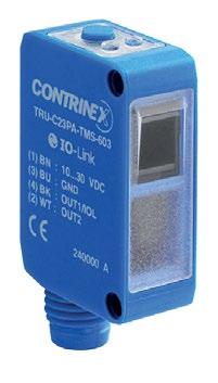
PHOTOELECTRIC SENSORS TRANSPARENT OBJECT CABLES Cable lengths available: 2 m, 5 m, 10 m other customised lengths possible A Group A: M8 3-pin Sub-group: Field attachable connectors Sub-group: Distribution boxes B Group B: M8 4-pin Sub-group: Field attachable connectors C Group C: M12 4-pin Sub-group: Field attachable connectors Sub-group: Distribution boxes D Group D: M12 AC/DC 3-pin E Group E: Universal mounting brackets Sub-group: Mechanical stops F Group F: Photoelectric mounting brackets G Group G: Photoelectric reflectors H Group H: Sensor tester Go to page 298 for details ACCESSORIES OPERATINGPRINCIPLE SENSING RANGE (mm) HOUSINGSIZE(mm) LIGHT SOURCEFAMILYCUBICC23–C23SERIESCUBICC23C23SERIESSupply Voltage range 10 30 VDC Output PNP Light-ON* * Other types available: PNP, NPN, Dark-ON, Light-ON COMMON FEATURES 160 Transparent reflex OPERATING PRINCIPLE OUTPUT [xx][x]-C23PA-[xxx]-[xxx] see p. 196 Sensor type [TR] Transparent reflex see p. 196Emission type [R] Red [U] UV Reference key on page 196 We made these pages with care, but we decline liability for any errors or omissions. 1,200 20 × 30 (C23) LED, UV 275 nm, Risk Group 2 1,200 20 × 30 (C23) LED, UV 275 nm, Risk Group 2 5,000 20 × 30 (C23) LED, red 630 nm 5,000 20 × 30 (C23) LED, red 630 nm 5,000 20 × 30 (C23) LED, red 630 nm 5,000 20 × 30 (C23) LED, red 630 nm


MATERIALHOUSING CABLE CONNECTOR FREQUENCYSWITCHING(Hz) TEMPERATUREAMBIENT PROTECTIONDEGREEOF PART REFERENCE * (SEEACCESSORIESPAGE160) KEY ADVANTAGES 9 interface available on PNP types 9 Versions with stability alarm as second output 9 Mutual interference immunity 9 Adjustment by teach button, potentiometer or 9 Enclosure rating IP67, Ecolab approved SERIESC23 C23CUBICVIEW DATASHEETSPHOTOELETRIC www.contrinex.com/collections/photoelectric-transparent-object Detailed data sheets for these products can be found on the Contrinex website: 161WWW.CONTRINEX.COM ABS PVC 1,000 −25 … +65°C IP67 TRU-C23PA-TMK-603 FGH ABS 1,000 −25 +65°C IP67 TRU-C23PA-TMS-603 BFGH ABS PVC 1,500 −25 +65°C IP67 TRR-C23PA-TMK-603 FGH ABS 1,500 −25 +65°C IP67 TRR-C23PA-TMS-603 BFGH ABS PVC 1,500 −25 … +65°C IP67 TRR-C23PA-PMK-603 FGH ABS 1,500 −25 +65°C IP67 TRR-C23PA-PMS-603 BFGH

Robotics
Printed circuit board production Presence sensing by industrial robot INDUSTRIES Packaging, logistics, materials handling, robotics, precision engineering, printed circuit board production, electronics, vending machines, special machinery, quality control APPLICATION
Photoelectric fiber-optic sensor detects broken parking-brake cable during manufacture During manufacture of automotive parking-brake cable, multiple strands of steel wire are twisted together, form ing a single cable. After twisting, cable passes to the next process in an unsupported, continuous length. Occasionally, the cable breaks, compromising safety and damaging equipment. Although the cable’s exact path is unpredictable, a multi-beam fiber-optic sensor detects its presence, interrupting the process if it breaks. Packaging systems


With self-contained fiber-optic sensors available in housings as small as 30 × 30 × 15 mm, and several models of small DIN-rail mounted amplifiers that accommodate multiple-sensor applications, the Contrinex range is highly versatile. A choice of synthetic or glass optical fibers provides options for even the most demanding applications. PRODUCT OVERVIEW OPTICAL FIBERS OVERVIEW KEY ADVANTAGES Fiber-optic sensors 9 Robust 3030 series (30 × 30 × 15 mm) 9 DIN-rail mounted 3060 series (31 × 60 × 10 mm) suitable for multiple-sensor applications 9 Distance setting by potentiometer or teach-in 9 Fibers 9 Large selection of types, including cylindrical light beam, multi-beam and low & high temperature 9 Diffuse or through-beam sensing, axial or radial 9 Synthetic fibers with bending radii from 2 mm, suitable for cutting on-site 9 Glass fibers for high temperatures and aggressive environment FIBER-OPTICPHOTOELECTRICSENSORSRELIABLESHORT-ANDLONG-RANGE SENSING SERIES Housing size mm 3030 30 × 30 × 15 3060 30 × 60 × 10 Fiber-optic amplifier (sn mm) 60 / 120 200 Housing size ∅2.3 mm M3 ∅3.2 mm M4 ∅4.5 mm M5 M6 18 × 32 mm fibersSynthetic Diffuse p. 168 p. 168 p. 170 p. 170 p. 168, 172 p. 168 Through-beam p. 170 p. 170 p. 172 p. 174 Glass fibers Diffuse p. 170 Through-beam p. 174


PHOTOELECTRIC SENSORS FIBER OPTIC CABLES Cable lengths available: 2 m, 5 m, 10 m other customised lengths possible A Group A: M8 3-pin Sub-group: Field attachable connectors Sub-group: Distribution boxes B Group B: M8 4-pin Sub-group: Field attachable connectors C Group C: M12 4-pin Sub-group: Field attachable connectors Sub-group: Distribution boxes D Group D: M12 AC/DC 3-pin E Group E: Universal mounting brackets Sub-group: Mechanical stops F Group F: Photoelectric mounting brackets G Group G: Photoelectric reflectors H Group H: Sensor tester Go to page 298 for details ACCESSORIES OPERATINGPRINCIPLE SENSING RANGE (mm) HOUSINGSIZE(mm) LIGHT SOURCEFAMILYCUBIC3030–3030SERIESCUBICAMPLIFIER30303030SERIESSupply Voltage range 10 36 VDC COMMON FEATURES 164 Through-beamDiffuse OPERATING PRINCIPLE OUTPUT L[x][x]-303[x]-[xxx] Sensor type [F] Fiber amplifier Connection [K] Cable [S] Connector see p. 197 [0] High performance [1] Standard Reference key on page 197 We made these pages with care, but we decline liability for any errors or omissions. 60 30 × 30 LED, red 660 nm 60 30 × 30 LED, red 660 nm 60 30 × 30 LED, red 660 nm 60 30 × 30 LED, red 660 nm 60 30 × 30 LED, red 660 nm 60 30 × 30 LED, red 660 nm 60 30 × 30 LED, red 660 nm 60 30 × 30 LED, red 660 nm 120 30 × 30 LED, red 660 nm 120 30 × 30 LED, red 660 nm 120 30 × 30 LED, red 660 nm 120 30 × 30 LED, red 660 nm or fiber)opticalselectedon(dependent


MATERIALHOUSING CABLE CONNECTOR FREQUENCYSWITCHING(Hz) TEMPERATUREAMBIENT PROTECTIONDEGREEOF PART REFERENCE (SEEACCESSORIESPAGE164)3030SERIESCUBIC3030VIEW DATASHEETSPHOTOELETRIC www.contrinex.com/collections/photoelectric-fiber-optic Detailed data sheets for these products can be found on the Contrinex website: 165WWW.CONTRINEX.COM KEY ADVANTAGES 9 Fiber-optic amplifiers in rugged Crastin housing 30 × 30 × 15 mm 9 Shock and vibration resistant due to fully potted electronics 9 Sensing range up to 120 mm PBTP (Crastin) PVC 1,000 −25 … +55°C IP67 LFK-3031-301 FH PBTP (Crastin) PVC 1,000 −25 +55°C IP67 LFK-3031-302 FH PBTP (Crastin) 1,000 −25 +55°C IP67 LFS-3031-301 AFH PBTP (Crastin) 1,000 −25 +55°C IP67 LFS-3031-302 AFH PBTP (Crastin) PVC 1,000 −25 … +55°C IP67 LFK-3031-303 FH PBTP (Crastin) PVC 1,000 −25 +55°C IP67 LFK-3031-304 FH PBTP (Crastin) 1,000 −25 +55°C IP67 LFS-3031-303 AFH PBTP (Crastin) 1,000 −25 +55°C IP67 LFS-3031-304 AFH PBTP (Crastin) PVC 1,000 −25 +55°C IP67 LFK-3030-101 FH PBTP (Crastin) 1,000 −25 +55°C IP67 LFS-3030-101 BFH PBTP (Crastin) PVC 1,000 −25 +55°C IP67 LFK-3030-103 FH PBTP (Crastin) 1,000 −25 +55°C IP67 LFS-3030-103 BFH

PHOTOELECTRIC SENSORS FIBER OPTIC CABLES Cable lengths available: 2 m, 5 m, 10 m other customised lengths possible A Group A: M8 3-pin Sub-group: Field attachable connectors Sub-group: Distribution boxes B Group B: M8 4-pin Sub-group: Field attachable connectors C Group C: M12 4-pin Sub-group: Field attachable connectors Sub-group: Distribution boxes D Group D: M12 AC/DC 3-pin E Group E: Universal mounting brackets Sub-group: Mechanical stops F Group F: Photoelectric mounting brackets G Group G: Photoelectric reflectors H Group H: Sensor tester Go to page 298 for details ACCESSORIES OPERATINGPRINCIPLE SENSING RANGE (mm) HOUSINGSIZE(mm) LIGHT SOURCEFAMILYCUBIC3060–3060SERIESCUBICAMPLIFIER30603060SERIESSupply Voltage range 10 30 VDC COMMON FEATURES 166 Through-beamDiffuse OPERATING PRINCIPLE OUTPUT L[x][x]-3[x]6[x]-[xxx] Sensor type [F] Fiber amplifier Connection [K] Cable [S] Connector see p. 197 [0] Red light [3] Blue light [0] Potentiometer [5] Teach [6] Digital display Reference key on page 197 We made these pages with care, but we decline liability for any errors or omissions. 100 31 × 60 LED, blue 465 nm 100 31 × 60 LED, blue 465 nm 100 31 × 60 LED, blue 465 nm 100 31 × 60 LED, blue 465 nm 200 31 × 60 LED, red 680 nm 200 31 × 60 LED, red 680 nm 200 31 × 60 LED, red 680 nm 200 31 × 60 LED, red 680 nm 200 31 × 60 LED, red 680 nm 200 31 × 60 LED, red 680 nm 200 31 × 60 LED, red 680 nm 200 31 × 60 LED, red 680 nm 200 31 × 60 LED, red 680 nm 200 31 × 60 LED, red 680 nm 200 31 × 60 LED, red 680 nm 200 31 × 60 LED, red 680 nm or fiber)opticalselectedon(dependent


MATERIALHOUSING CABLE CONNECTOR FREQUENCYSWITCHING(Hz) TEMPERATUREAMBIENT PROTECTIONDEGREEOF PART REFERENCE (SEEACCESSORIESPAGE166)3060SERIESCUBIC3060 Detailed data sheets for these products can be found on the Contrinex website: 167WWW.CONTRINEX.COM KEY ADVANTAGES 9 Complete series of fiber-optic amplifiers for plastic fibers and DIN-rail mounting 9 Small housings 31 × 60 × 10 mm 9 Sensing ranges up to 200 mm 9 IO-Link 9 Blue light version for glass detection VIEW DATASHEETSPHOTOELETRIC www.contrinex.com/collections/photoelectric-fiber-optic PBTP (Crastin) PVC 1,500 −25 … +55°C IP64 LFK-3360-101 H PBTP (Crastin) 1,500 −25 +55°C IP64 LFS-3360-101 BH PBTP (Crastin) PVC 1,500 −25 +55°C IP64 LFK-3360-103 H PBTP (Crastin) 1,500 −25 +55°C IP64 LFS-3360-103 BH PBTP (Crastin) PVC 1,500 −25 … +55°C IP64 LFK-3065-101 H PBTP (Crastin) 1,500 −25 +55°C IP64 LFS-3065-101 BH PBTP (Crastin) PVC 1,500 −25 +55°C IP64 LFK-3065-103 H PBTP (Crastin) 1,500 −25 +55°C IP64 LFS-3065-103 BH PBTP (Crastin) PVC 1,500 −25 +55°C IP64 LFK-3060-101 H PBTP (Crastin) 1,500 −25 +55°C IP64 LFS-3060-101 BH PBTP (Crastin) PVC 1,500 −25 +55°C IP64 LFK-3060-103 H PBTP (Crastin) 1,500 −25 +55°C IP64 LFS-3060-103 BH PBTP (Crastin) PVC 4,000 −25 +55°C IP64 LFK-3066-101 H PBTP (Crastin) 4,000 −25 … +55°C IP64 LFS-3066-101 BH PBTP (Crastin) PVC 4,000 −25 +55°C IP64 LFK-3066-403 H PBTP (Crastin) 4,000 −25 +55°C IP64 LFS-3066-403 BH

PHOTOELECTRIC SENSORS OPTICAL FIBERS OPERATINGPRINCIPLE SENSING RANGE (mm) MATERIALFIBER HOUSINGSIZE(mm)FAMILYOPTICALFIBERSFIBERSSYNTHETIC & GLASS 168 Through-beamDiffuse OPERATING PRINCIPLE OUTPUT L[x][x]-[xxxx]-[xxx]-[xxx] Sensor type [F] Fiber amplifier [G] Glass optical fiber [P] Synthetic optical fiber see p. 197 see p. 197 see p. 197 Reference key on page 197 We made these pages with care, but we decline liability for any errors or omissions. 40 Plastic ∅ 2.3 40 Plastic M3 40 Plastic M3 90 Plastic M6 90 Plastic M6 90 Plastic 18 × 32

LENGTHCABLE MATERIALSLEEVE TEMPERATURERANGE TECHNICAL DRAWING PART REFERENCEOPTICALFIBERS Detailed data sheets for these products can be found on the Contrinex website: 169WWW.CONTRINEX.COM KEY ADVANTAGES 9 Very small dimensions 9 Long sensing ranges 9 Small bending radii 9 Can be cut on site 9 Large selection of types 9 Mechanically rugged sensing head VIEW DATASHEETSPHOTOELETRIC www.contrinex.com/collections/photoelectric-fiber-optic 2 m PE −25 +70°C LFP-1012-020 2 m PE −25 +70°C LFP-1001-020 2 m PE −25 +70°C LFP-1004-020 2 m PE −25 +70°C LFP-1102-020 2 m PE −55 +105°C LFP-1002-020-002 2 m PE −25 … +70°C LFP-1011-020
PHOTOELECTRIC SENSORS OPTICAL FIBERS OPERATINGPRINCIPLE SENSING RANGE (mm) MATERIALFIBER HOUSINGSIZE(mm)FAMILYOPTICALFIBERSFIBERSSYNTHETIC & GLASS 170 Through-beamDiffuse OPERATING PRINCIPLE OUTPUT L[x][x]-[xxxx]-[xxx]-[xxx] Sensor type [F] Fiber amplifier [G] Glass optical fiber [P] Synthetic optical fiber see p. 197 see p. 197 see p. 197 Reference key on page 197 We made these pages with care, but we decline liability for any errors or omissions. 100 Plastic ∅ 4.5 100 Plastic M5 120 Plastic M3 120 Plastic M3 120 Plastic ∅ 3.2 120 Glass M6
LENGTHCABLE MATERIALSLEEVE TEMPERATURERANGE TECHNICAL DRAWING PART REFERENCEOPTICALFIBERS Detailed data sheets for these products can be found on the Contrinex website: 171WWW.CONTRINEX.COM KEY ADVANTAGES 9 Very small dimensions 9 Long sensing ranges 9 Small bending radii 9 Can be cut on site 9 Large selection of types 9 Mechanically rugged sensing head VIEW DATASHEETSPHOTOELETRIC www.contrinex.com/collections/photoelectric-fiber-optic 2 m PE −25 +70°C LFP-1006-020 2 m PE −25 +70°C LFP-1007-020 2 m PE −25 +70°C LFP-2001-020 2 m PE −25 +70°C LFP-2003-020 2 m PE −25 +70°C LFP-2006-020 0.5 m Brass sleeve −25 … +160°C LFG-1022-050
PHOTOELECTRIC SENSORS OPTICAL FIBERS OPERATINGPRINCIPLE SENSING RANGE (mm) MATERIALFIBER HOUSINGSIZE(mm)FAMILYOPTICALFIBERSFIBERSSYNTHETIC & GLASS 172 Through-beamDiffuse OPERATING PRINCIPLE OUTPUT L[x][x]-[xxxx]-[xxx]-[xxx] Sensor type [F] Fiber amplifier [G] Glass optical fiber [P] Synthetic optical fiber see p. 197 see p. 197 see p. 197 Reference key on page 197 We made these pages with care, but we decline liability for any errors or omissions. 120 Plastic M6 120 Plastic M6 120 Plastic M6 120 Plastic M6 150 Plastic M6 300 Plastic M4
LENGTHCABLE MATERIALSLEEVE TEMPERATURERANGE TECHNICAL DRAWING PART REFERENCEOPTICALFIBERS Detailed data sheets for these products can be found on the Contrinex website: 173WWW.CONTRINEX.COM KEY ADVANTAGES 9 Very small dimensions 9 Long sensing ranges 9 Small bending radii 9 Can be cut on site 9 Large selection of types 9 Mechanically rugged sensing head VIEW DATASHEETSPHOTOELETRIC www.contrinex.com/collections/photoelectric-fiber-optic 2 m PE −25 +70°C LFP-1002-020 2 m PE −25 +70°C LFP-1005-020 2 m PE −25 +70°C LFP-1003-020 2 m PE −25 +70°C LFP-1013-020 2 m PE −25 +70°C LFP-1202-020 2 m PE −25 … +70°C LFP-2102-020
PHOTOELECTRIC SENSORS OPTICAL FIBERS OPERATINGPRINCIPLE SENSING RANGE (mm) MATERIALFIBER HOUSINGSIZE(mm)FAMILYOPTICALFIBERSFIBERSSYNTHETIC & GLASS 174 Through-beamDiffuse OPERATING PRINCIPLE OUTPUT L[x][x]-[xxxx]-[xxx]-[xxx] Sensor type [F] Fiber amplifier [G] Glass optical fiber [P] Synthetic optical fiber see p. 197 see p. 197 see p. 197 Reference key on page 197 We made these pages with care, but we decline liability for any errors or omissions. 300 Plastic M4 400 Plastic M4 400 Plastic M4 500 Glass M4 500 Plastic M4 1,100 Plastic M6
LENGTHCABLE MATERIALSLEEVE TEMPERATURERANGE TECHNICAL DRAWING PART REFERENCEOPTICALFIBERS Detailed data sheets for these products can be found on the Contrinex website: 175WWW.CONTRINEX.COM KEY ADVANTAGES 9 Very small dimensions 9 Long sensing ranges 9 Small bending radii 9 Can be cut on site 9 Large selection of types 9 Mechanically rugged sensing head VIEW DATASHEETSPHOTOELETRIC www.contrinex.com/collections/photoelectric-fiber-optic 2 m PE −55 +105°C LFP-2002-020-002 2 m PE −25 +70°C LFP-2002-020 2 m PE −25 +70°C LFP-2004-020 0.5 m Brass sleeve −25 +160°C LFG-3022-050 2 m PE −25 +70°C LFP-2202-020 2 m PE −25 … +70°C LFP-2005-020
Position control in furniture factory Sensing and measuring shelf space
PackagingLogistics systems
INDUSTRIES Packaging, logistics, materials handling, woodworking industry, quality control, precision engineering, printed circuit board production APPLICATION Distance sensor with IO-Link 1.1 profile detects presence of goods on shelf and measures available shelf space In a warehouse with an intelligent logistics concept, a robot arm must reliably detect whether goods are on the shelf and measure any available shelf space. With its ability to measure distances of up to 5,000 mm pre cisely, the C55 distance sensor is perfectly suited for this task. Using its IO-Link interface, it transmits the measurements directly to the control system as millime ter values in digital form, enabling optimal use of ware house space.


As contactless measurement devices, photoelectric Distance sensors are suitable for numerous areas of application. C23 types use a triangulation method for accurate distance measurement at short range. For longer ranges, the optical time-of-flight (TOF) method is used by C55 types. Distance measurement is largely independent of target color or surface characteristics and repeatability is high. PRODUCT ACCESSORIESOVERVIEW Go to page 298 to see all the accessories KEY ADVANTAGES C23 distance-measuring sensors 9 Two distance-measurement ranges: 20 80 mm and 30 200 mm 9 Housing 20 × 34 × 12 mm 9 High precision and repeatability 9 Settable analog range for optimum distance measurement 9 Enclosure rating IP67/IP69K C55 distance-measuring sensors 9 Distance measurement up to 5,000 mm 9 Housing 50 × 50 × 23 mm 9 High precision and repeatability 9 Settable analog range for optimum distance measurement 9 Enclosure rating IP67/IP69K, Ecolab approved 9 DISTANCEPHOTOELECTRICSENSORSHIGHPRECISIONANDDIRECT DIGITAL TRANSMISSIONSERIES Housing size mm C23 20 × 34 × 12 C55 50 × 50 × 23 snmm Short range 80 / 100 / 200 Medium range 5,000 Cables Mounting brackets


PHOTOELECTRIC SENSORS DISTANCE CABLES Cable lengths available: 2 m, 5 m, 10 m other customised lengths possible A Group A: M8 3-pin Sub-group: Field attachable connectors Sub-group: Distribution boxes B Group B: M8 4-pin Sub-group: Field attachable connectors C Group C: M12 4-pin Sub-group: Field attachable connectors Sub-group: Distribution boxes D Group D: M12 AC/DC 3-pin E Group E: Universal mounting brackets Sub-group: Mechanical stops F Group F: Photoelectric mounting brackets G Group G: Photoelectric reflectors H Group H: Sensor tester Go to page 298 for details ACCESSORIES OPERATINGPRINCIPLE SENSING RANGE (mm) HOUSINGSIZE(mm) LIGHT SOURCEFAMILYCUBICC23–C23SERIESCUBICC23C23SERIESSupply Voltage range 13 30 VDC COMMON FEATURES 178 Distance diffuse OPERATING PRINCIPLE OUTPUT [xx][x]-C23PB-[xxx]-[xxx]-[xxx] see p. 196 Sensor type [DT] Distance diffuse see p. 196Emission type [L] Laser [R] Red see p. 196 Reference key on page 196 We made these pages with care, but we decline liability for any errors or omissions. 80 20 × 34 (C23) LED, red 632 nm 80 20 × 34 (C23) LED, red 632 nm 100 20 × 34 (C23) Laser class 1, red 650 nm 200 20 × 34 (C23) LED, red 632 nm 200 20 × 34 (C23) LED, red 632 nm

MATERIALHOUSING CABLE CONNECTOR FREQUENCYSWITCHING(Hz) TEMPERATUREAMBIENT PROTECTIONDEGREEOF PART REFERENCE (SEEACCESSORIESPAGE178) KEY ADVANTAGES 9 Two distance measurement ranges: 20 80 mm and 30 200 mm 9 Housing 20 × 34 × 12 mm 9 High precision and repeatability 9 Settable analog range for optimum distance measurement 9 Enclosure rating IP67 / IP69K SERIESC23 C23CUBICVIEW DATASHEETSPHOTOELETRIC www.contrinex.com/collections/photoelectric-distance Detailed data sheets for these products can be found on the Contrinex website: 179WWW.CONTRINEX.COM ABS 1,000 −20 … +60°C IP67 / IP69K DTR-C23PB-TMS-139 BFH ABS 1,000 −20 +60°C IP67 / IP69K DTR-C23PB-TMS-129 BFH ABS 1,000 −20 +60°C IP67 / IP69K DTL-C23PB-TMS-139-501 BFH ABS 1,000 −20 +60°C IP67 / IP69K DTR-C23PB-TLS-139 BFH ABS 1,000 −20 +60°C IP67 / IP69K DTR-C23PB-TLS-129 BFH
PHOTOELECTRIC SENSORS DISTANCE CABLES Cable lengths available: 2 m, 5 m, 10 m other customised lengths possible A Group A: M8 3-pin Sub-group: Field attachable connectors Sub-group: Distribution boxes B Group B: M8 4-pin Sub-group: Field attachable connectors C Group C: M12 4-pin Sub-group: Field attachable connectors Sub-group: Distribution boxes D Group D: M12 AC/DC 3-pin E Group E: Universal mounting brackets Sub-group: Mechanical stops F Group F: Photoelectric mounting brackets G Group G: Photoelectric reflectors H Group H: Sensor tester Go to page 298 for details ACCESSORIES OPERATINGPRINCIPLE SENSING RANGE (mm) HOUSINGSIZE(mm) LIGHT SOURCEFAMILYCUBICC55–C55SERIESCUBICC55C55SERIESSupply Voltage range 18 30 VDC COMMON FEATURES 180 Distance diffuse OPERATING PRINCIPLE OUTPUT [xx][x]-C55PA-[xxx]-[xxx]-[xxx] see p. 196 Sensor type [DT] Distance diffuse see p. 196Emission type [L] Laser see p. 196 Reference key on page 196 We made these pages with care, but we decline liability for any errors or omissions. 5,000 50 × 50 (C55) Laser class 1, red 655 nm 5,000 50 × 50 (C55) Laser class 1, red 655 nm 5,000 50 × 50 (C55) Laser class 1, red 655 nm


MATERIALHOUSING CABLE CONNECTOR FREQUENCYSWITCHING(Hz) TEMPERATUREAMBIENT PROTECTIONDEGREEOF PART REFERENCE (SEEACCESSORIESPAGE180) KEY ADVANTAGES 9 Distance measurement up to 5,000 mm 9 Housing 50 × 50 × 23 mm 9 High precision and repeatability 9 Settable analog range for optimum distance measurement 9 Enclosure rating IP67 / IP69K, Ecolab approved 9 SERIESC55 C55CUBIC Detailed data sheets for these products can be found on the Contrinex website: 181WWW.CONTRINEX.COM VIEW DATASHEETSPHOTOELETRIC www.contrinex.com/collections/photoelectric-distance ABS 250 −40 … +60°C IP67 / IP69K DTL-C55PA-TMS-119-502 CFH ABS 250 −40 +60°C IP67 / IP69K DTL-C55PA-TMS-119-503 CFH ABS 500 −40 +60°C IP67 / IP69K DTL-C55PA-TMS-407-505 CFH

Contrast sensor checks label alignment and confirms presence of print markings during packaging operations During high-volume production of confectionery, sealed cartons of bagged candy travel by conveyor to a label ing station. A photoelectric contrast sensor, mounted beside the conveyor, checks the label alignment and confirms the presence of print markings as each carton leaves the labeling area. If a label is blank, illegible or wrongly positioned, the carton is diverted to a holding area for investigation.
Color sorting on drinks conveyor
INDUSTRIES Packaging, logistics, materials handling, food and beverage, filling machines, printing, quality control, sorting processes, tobacco industry, wood processing machines
APPLICATION
Print-mark detection on label machine
Detection of anodized products
Detection of marks on cartons


Color sensors detect variations in target color, allowing color sorting or checking. Up to three separate outputs can be programmed using the teach-in function. Contrast sensors are ideal for detecting print marks in printing, labeling and packaging processes. With excellent resolution and five tolerance levels, detection is accurate, even when color or contrast differences are minimal. PRODUCT ACCESSORIESOVERVIEW Go to page 298 to see all the accessories KEY ADVANTAGES 9 Rugged housing, 40 × 50 × 15 mm 9 Connector adjustable at 0°, 45° and 90° 9 5 switching tolerance levels Color sensors 9 Three color-teach channels with independent outputs 9 High positioning tolerance 9 High switching frequency: up to 4 kHz Contrast sensors 9 Detection of very small print marks thanks to a narrow, collimated light spot 9 RGB emission technology with best emission color auto matically selected 9 Excellent tolerance to target distance variations 9 High switching frequency: up to 10 kHz COLOR CONTRASTANDPHOTOELECTRICSENSORSEXCELLENTRESOLUTIONFOR SMALLEST VARIATIONSSERIES Housing size mm 4050 Color 40 × 50 × 15 4050 Contrast 40 × 50 × 15 Diffuse (sn mm) 40 12 Cables Mounting brackets


PHOTOELECTRIC SENSORS COLOR AND CONTRAST CABLES Cable lengths available: 2 m, 5 m, 10 m other customised lengths possible A Group A: M8 3-pin Sub-group: Field attachable connectors Sub-group: Distribution boxes B Group B: M8 4-pin Sub-group: Field attachable connectors C Group C: M12 4-pin Sub-group: Field attachable connectors Sub-group: Distribution boxes D Group D: M12 AC/DC 3-pin E Group E: Universal mounting brackets Sub-group: Mechanical stops F Group F: Photoelectric mounting brackets G Group G: Photoelectric reflectors H Group H: Sensor tester Go to page 298 for details ACCESSORIES OPERATINGPRINCIPLE SENSING RANGE (mm) HOUSINGSIZE(mm) LIGHT SOURCEFAMILYCUBIC4050–4050SERIESCUBIC40504050SERIESSupply Voltage range 10 30 VDC COMMON FEATURES 184 Diffuse (Color) Diffuse (Contrast) OPERATING PRINCIPLE OUTPUT [x][x][x]-4155-[xxx] Sensor type [T] Diffuse Connection [K] Cable [S] Connector see p. 197 [F] Color sensor [K] Contrast sensor Reference key on page 197 We made these pages with care, but we decline liability for any errors or omissions. 40 40 × 50 LED, white 40 40 × 50 LED, white 12 40 × 50 LED, RGB 12 40 × 50 LED, RGB


MATERIALHOUSING CABLE CONNECTOR FREQUENCYSWITCHING(Hz) TEMPERATUREAMBIENT PROTECTIONDEGREEOF PART REFERENCE (SEEACCESSORIESPAGE184)4050SERIESCUBIC4050VIEW DATASHEETSPHOTOELETRIC www.contrinex.com/collections/photoelectric-color-and-contrast Detailed data sheets for these products can be found on the Contrinex website: 185WWW.CONTRINEX.COM KEY ADVANTAGES 9 Rugged housing, 40 × 50 × 15 mm 9 Connector adjustable at 0°, 45° and 90° 9 5 switching tolerance levels Color sensors 9 3 color teach channels with independent outputs 9 High positioning tolerance 9 High switching frequency: up to 4 kHz Contrast sensors 9 Detection of very small print marks thanks to a narrow, collimated light spot 9 RGB emission technology with best emission color automatically selected 9 Excellent tolerance to target distance variations 9 High switching frequency: up to 10 kHz PBTP 4,000 −5 … +55°C IP67 FTS-4155-301 CFH PBTP 4,000 −5 +55°C IP67 FTS-4155-303 CFH PBTP 10,000 −5 +55°C IP67 KTS-4155-407 CFH PBTP PVC 10,000 −5 +55°C IP67 KTK-4155-407 FH

Logistics
Infrared light grids detect misshapen and oversize carton packs after automated shrink-wrapping process During high-volume packaging operations, conveyors deliver stacked cartons to shrink-wrapping stations. At each station, a wrapping machine encloses a stack in heat-shrink film and an infrared oven shrinks the film to form a sealed pack of cartons. An infrared-light mea surement grid, mounted beside the conveyor, checks the dimensions of each pack as it leaves the oven and signals a plant-wide control system if a wrapped pack is misshapen or oversize.
Counting of small objects Carton measurement and sorting INDUSTRIES Packaging, logistics, materials handling, assembly, automation, laundry industry, small parts production, woodworking industry
Packagingsystemssystems
APPLICATION


Contrinex’s robust, plug-and-play light grids offer fast response times, reliable detection of the most varied objects and immunity to interference from ambient light. DGI detection grids can detect objects with diameters of 0.9, 2, 4, 8 or 25 mm, depending on type. MGI measurement grids can measure the dimensions of a detected object, and determine its position. PRODUCT ACCESSORIESOVERVIEW Go to page 298 to see all the accessories KEY ADVANTAGES 9 Plug-and-play installation 9 Small installation space with cross-section: 40 × 20.5 mm Detection grids 9 Fast response time 0.8 ms 4.8 ms 9 Ideal for detection and counting of even the smallest objects 9 Resolution: 0.9 mm, 2 mm, 4 mm, 8 mm or 25 mm 9 Detection height: up to 2,010 mm Measurement grids 9 Ideal for position and dimension control 9 Center beam spacing: 5 mm or 12 mm 9 Analog output 0–10 V or 4–20 mA 9 Measurement height: up to 1,418 mm Cables LIGHT SENSORSPHOTOELECTRICGRIDSFASTDETECTION,COUNTINGANDMEASUREMENTSERIES Housing size mm DGI 40 × 20.5 × H MGI 40 × 20.5 × H snmm Detection grids 8,000 Measurement grids 4,000 Mounting bracket


PHOTOELECTRIC SENSORS LIGHT GRIDS CABLES Cable lengths available: 2 m, 5 m, 10 m other customised lengths possible A Group A: M8 3-pin Sub-group: Field attachable connectors Sub-group: Distribution boxes B Group B: M8 4-pin Sub-group: Field attachable connectors C Group C: M12 4-pin Sub-group: Field attachable connectors Sub-group: Distribution boxes D Group D: M12 AC/DC 3-pin E Group E: Universal mounting brackets Sub-group: Mechanical stops F Group F: Photoelectric mounting brackets G Group G: Photoelectric reflectors H Group H: Sensor tester Go to page 298 for details ACCESSORIES OPERATINGPRINCIPLE DETECTION RANGE (mm) HOUSINGSIZE(mm) LIGHT SOURCEFAMILYDETECTIONGRIDS–DGISERIESDETECTION GRIDS DGI SERIES 188 Detection grid OPERATING PRINCIPLE Supply Voltage 24 VDC Polarity Push-Pull Temperature range 5 +50°C Enclosure rating IP65 COMMON FEATURES OUTPUT DGI-[xx]A-[xxxx]-[xxx]-[xxx] Dimensions [####] Beam height in mm see p. 198 [##] Resolution in mm see p. 198 Reference key on page 198 We made these pages with care, but we decline liability for any errors or omissions. 800 40 × 20.5 (Light Grid) LED,880infrarednm 800 40 × 20.5 (Light Grid) LED,880infrarednm 400 40 × 20.5 (Light Grid) LED,880infrarednm 400 40 × 20.5 (Light Grid) LED,880infrarednm 800 40 × 20.5 (Light Grid) LED,880infrarednm 800 40 × 20.5 (Light Grid) LED,880infrarednm 4,000 40 × 20.5 (Light Grid) LED,880infrarednm 4,000 40 × 20.5 (Light Grid) LED,880infrarednm 8,000 40 × 20.5 (Light Grid) LED,880infrarednm 8,000 40 × 20.5 (Light Grid) LED,880infrarednm 8,000 40 × 20.5 (Light Grid) LED,880infrarednm


MATERIALHOUSING CABLE CONNECTOR RESOLUTION(mm) LIGHT HEIGHTGRID(mm) OUTPUT 1 OUTPUT 2 PART REFERENCE (SEEACCESSORIESPAGE188)LIGHTGRIDSDGISERIESVIEW DATASHEETSPHOTOELECTRIC www.contrinex.com/collections/photoelectric-light-grids Detailed data sheets for these products can be found on the Contrinex website: 189WWW.CONTRINEX.COM KEY ADVANTAGES 9 Compact aluminum housing (40 × 20.5 mm × height) 9 Resolution of 0.9 mm to 25 mm, capable of detecting even the smallest object 9 Detection range up to 8,000 mm 9 Beam height from 75 mm up to 2,010 mm 9 Two push-pull outputs (PNP + NPN), Light-ON + Dark-ON 9 Fast response time from 0.8 to 4.8 ms 9 Potentiometer for fine adjustment on 0.9 mm and 2 mm resolution grids Aluminum 2 100 Light-ON Dark-ON DGI-02A-0075-PMS-107 CF Aluminum 4 100 Light-ON Dark-ON DGI-04A-0075-NMS-107 CF Aluminum 0.9 100 Light-ON Dark-ON DGI-01A-0075-PMS-107 CF Aluminum 0.9 180 Light-ON Dark-ON DGI-01A-0155-PMS-107 CF Aluminum 2 180 Light-ON Dark-ON DGI-02A-0155-PMS-107 CF Aluminum 4 180 Light-ON Dark-ON DGI-04A-0155-NMS-107 CF Aluminum 8 212 Light-ON Dark-ON DGI-08A-0190-NMS-107 CF Aluminum 8 500 Light-ON Dark-ON DGI-08A-0480-NMS-107 CF Aluminum 25 500 Light-ON Dark-ON DGI-25A-0480-NMS-107 CF Aluminum 25 980 Light-ON Dark-ON DGI-25A-0960-NMS-107 CF Aluminum 25 2,036 Light-ON Dark-ON DGI-25A-2010-NMS-107 CF

PHOTOELECTRIC SENSORS LIGHT GRIDS CABLES Cable lengths available: 2 m, 5 m, 10 m other customised lengths possible A Group A: M8 3-pin Sub-group: Field attachable connectors Sub-group: Distribution boxes B Group B: M8 4-pin Sub-group: Field attachable connectors C Group C: M12 4-pin Sub-group: Field attachable connectors Sub-group: Distribution boxes D Group D: M12 AC/DC 3-pin E Group E: Universal mounting brackets Sub-group: Mechanical stops F Group F: Photoelectric mounting brackets G Group G: Photoelectric reflectors H Group H: Sensor tester Go to page 298 for details ACCESSORIES OPERATINGPRINCIPLE SENSING RANGE (mm) HOUSINGSIZE(mm) LIGHT SOURCEFAMILYMEASUREMENTGRIDS–MGISERIESMEASUREMENT GRIDS MGI SERIES 190 Measurement grid OPERATING PRINCIPLE Supply Voltage 24 VDC Polarity Analog Temperature range 5 +50°C Enclosure rating IP65 COMMON FEATURES OUTPUT MGI-[xx]A-[xxxx]-[xxx]-[xxx] Dimensions [####] Beam height in mm see p. 198 [##] Center beam spacing in mm see p. 198 Reference key on page 198 We made these pages with care, but we decline liability for any errors or omissions. 4,000 40 × 20.5 (Light Grid) LED,880infrarednm 4,000 40 × 20.5 (Light Grid) LED,880infrarednm 4,000 40 × 20.5 (Light Grid) LED,880infrarednm 4,000 40 × 20.5 (Light Grid) LED,880infrarednm 4,000 40 × 20.5 (Light Grid) LED,880infrarednm 4,000 40 × 20.5 (Light Grid) LED,880infrarednm

MATERIALHOUSING CABLE CONNECTOR RESOLUTION(mm) LIGHT HEIGHTGRID(mm) OUTPUT 1 OUTPUT 2 PART REFERENCE (SEEACCESSORIESPAGE190)LIGHTGRIDSMGISERIES Detailed data sheets for these products can be found on the Contrinex website: 191WWW.CONTRINEX.COM KEY ADVANTAGES 9 Compact aluminum housing (40 × 20.5 mm × height) 9 Center beam spacing 5 mm and 12 mm 9 Measurement range up to 4,000 mm 9 Beam height from 230 mm up to 1,420 mm 9 Analog output 0–10 V or 4–20 mA 9 Fast response time from 3 to 14 ms 9 Four switching modes selectable through multi-switch VIEW DATASHEETSPHOTOELECTRIC www.contrinex.com/collections/photoelectric-light-grids Aluminum 0.3 m PUR 6 260 4 … 20 mA 0 … 10 V MGI-05A-0232-NMS-149 CF Aluminum 0.3 m PUR 6 500 4 20 mA 0 10 V MGI-05A-0472-NMS-149 CF Aluminum 0.3 m PUR 6 980 4 20 mA 0 10 V MGI-05A-0952-NMS-149 CF Aluminum 0.3 m PUR 14 500 4 20 mA 0 10 V MGI-12A-0458-NMS-149 CF Aluminum 0.3 m PUR 14 980 4 … 20 mA 0 … 10 V MGI-12A-0938-NMS-149 CF Aluminum 0.3 m PUR 14 1,460 4 20 mA 0 10 V MGI-12A-1418-NMS-149 CF
INDUSTRIES Robotics, packaging, materials handling, logistics, food and beverage Packaging systems Robotics
Beverage
APPLICATION
Photoelectric fork sensor checks presence of plastic cap and eliminates downtime During continuous production of fast-moving consumer goods, line stoppages are both costly and time consuming. After fill ing, sealing and capping, bottles of table sauces proceed for labelling and packaging; at this stage, the undetected absence of a plastic cap from an individual bottle requires manual inter vention and potentially the rejection of an entire batch of pro duction. A highly versatile photoelectric fork sensor, positioned directly over the conveyor, senses the presence of a cap on each bottle prior to labelling and triggers an alarm if a cap is missing. Contrinex fork light-barrier sensors with industry-stan dard IO-Link communication are ideal for this application, offering designers four discrete operating modes and switch ing frequencies up to 14,000 Hz. With a standard resolution of 0.3 mm (down to 0.1 mm in high-resolution mode) and fork openings from 10 mm to 120 mm, these robust, metal-cased sensors are well suited to both the task and the environment. filling machines
Conveyor systems


FORKSENSORSPHOTOELECTRICSENSORSROBUSTSPACE-SAVINGDESIGNOFFERSVERSATILITYANDSIMPLICITY Contrinex fork light-barrier sensors offer a powerful combination of simplicity, multi-mode operation and compactness, with highresolution and high-speed sensing as standard. Ideal for general position- and presence-sensing in industrial environments, these versatile, metal-cased devices allow four modes of operation – standard, high-resolution, power and highspeed – and the convenience of a push-pull output. Equipped with the industry-standard IO-Link protocol, they provide a choice of manual or remote set-up and adjustment, simplifying installation while saving time and money. PRODUCT ACCESSORIESOVERVIEW Go to page 298 to see all the accessories KEY ADVANTAGES 9 High resolution: ∅ 0.1–0.2 mm 9 High frequency up to 14 kHz 9 4 sensor modes: Standard, High Resolution, Power, Speed 9 v1.1 9 Sensitivity adjustment allowing detection of transparent objects 9 Compact design accommodates photoelectric emitter and receiver in a single housing 9 Push-pull output keeps inventory costs down while allowing exceptional flexibility 9 Robust space-saving housing ensures precise alignment requiring no on-site adjustment SERIES Housing size mm U 10 25×45×10 U 20 40×50×10 U 30 50×60×10 U 40 60×70×10 U 50 70×80×10 U 80 100×80×10 U 11 120×80×10 U 12 144×90×12 Through-beam (sn mm) 10 20 30 40 50 80 100 120 Sensor testerCables


PHOTOELECTRIC SENSORS FORK CABLES Cable lengths available: 2 m, 5 m, 10 m other customised lengths possible A Group A: M8 3-pin Sub-group: Field attachable connectors Sub-group: Distribution boxes B Group B: M8 4-pin C Group C: M12 4-pin Sub-group: Field attachable connectors Sub-group: Distribution boxes D Group D: M12 AC/DC 3-pin E Group E: Universal mounting brackets Sub-group: Mechanical stops F Group F: Photoelectric mounting brackets G Group G: Photoelectric reflectors H Group H: Sensor tester Go to page 298 for details ACCESSORIES OPERATINGPRINCIPLE SENSING RANGE (mm) OPENINGFORK(mm) LIGHT SOURCEFAMILYU-SHAPEFORKSENSORS–LGSERIESU-SHAPE FORK SENSORS LG SERIES Supply Voltage range 10 30 VDC Output Light-ON / Dark-ON / IO-Link Ambient temperature −25 … +60°C COMMON FEATURES 194 Through-beam OPERATING PRINCIPLE OUTPUT LG[x]-U[xx]MA-[xxx]-[xxx] see p. 196 see p. 196Emission type [I] Infrared [R] Red Reference key on page 196 Housing size [##] Fork opening in mm We made these pages with care, but we decline liability for any errors or omissions. 10 10 LED,880infrarednm 20 20 LED, red 660 nm 30 30 LED, red 660 nm 40 40 LED, red 660 nm 50 50 LED, red 660 nm 80 80 LED, red 660 nm 100 100 LED, red 660 nm 120 120 LED, red 660 nm

MATERIALHOUSING CABLE CONNECTOR FREQUENCYSWITCHING(Hz) RESOLUTION(mm) PROTECTIONDEGREEOF PART REFERENCE (SEEACCESSORIESPAGE194) KEY ADVANTAGES 9 High resolution: ∅ 0.1–0.2 mm 9 High frequency up to 14 kHz 9 Four sensor modes: Standard, High Resolution, Power, Speed 9 v1.1 9 Sensitivity adjustment allowing detection of transparent objects 9 Compact design accommodates photoelectric emitter and receiver in a single housing 9 Push-pull output keeps inventory costs down while allowing exceptional flexibility 9 Robust space-saving housing ensures precise alignment requiring no on-site adjustment SERIESLG FORKU-SHAPE SENSORSVIEW DATASHEETSPHOTOELECTRIC www.contrinex.com/collections/photoelectric-fork Detailed data sheets for these products can be found on the Contrinex website: 195WWW.CONTRINEX.COM Die-cast zinc 10,000 0.2 IP67 LGI-U10MA-PMS-407 AH Die-cast zinc 5,000 0.3 IP67 LGR-U20MA-PMS-407 AH Die-cast zinc 5,000 0.3 IP67 LGR-U30MA-PMS-407 AH Die-cast zinc 5,000 0.3 IP67 LGR-U40MA-PMS-407 AH Die-cast zinc 5,000 0.3 IP67 LGR-U50MA-PMS-407 AH Die-cast zinc 5,000 0.3 IP67 LGR-U80MA-PMS-407 AH Die-cast zinc 5,000 0.3 IP67 LGR-U11MA-PMS-407 AH Die-cast zinc 5,000 0.5 IP67 LGR-U12MA-PMS-407 AH
Detailed data sheets for these products can be found on the Contrinex website:196 PHOTOELECTRIC SENSORS REFERENCE KEY Diffuse LT Retro-reflex LR Through-beam LL Background suppression LH Distance diffuse DT Transparent retro-reflex TR Fork light barrier LGLTR-C23PA-PMS-403 (-XXX) Red R Laser L UV U Infrared I Short S Standard M Long L Extra long X Cable K Connector S Cable + connector V Cubic C Cylindrical threaded M Cylindrical smooth D U-Shape U Cubic 1# mm × 2# mm 12 Cubic 2# mm × 3# mm 23 Cubic 5# mm × 5# mm 55 Cylindrical 4 mm 04 Cylindrical 5 mm 05 Cylindrical 18 mm 18 U-Shape, fork opening in mm ## Plastic P Metal M Standard A, B 4-wire devices, NPN Light-ON + Dark-ON 01 Light-ON + stability alarm 0A Dark-ON + stability alarm 0B 4-wire devices, PNP Light-ON + Dark-ON 03 Light-ON + stability alarm 0C Dark-ON + stability alarm 0D 3-wire devices, NPN Light-ON 01 Dark-ON 02 3-wire devices, PNP Light-ON 03 Dark-ON 04 Other 3- or 4-wire through-beam sensor (emitter) 00 Push-pull output 07 Analog #9 Special ## No teach or potentiometer N Potentiometer P Teach button T Teach wire W NEW DESIGNATION SINCE 2013 SENSOR PERFORMANCEHOUSINGHOUSINGHOUSINGEMISSIONTYPETYPETYPESIZEMATERIAL CONNECTION TYPE DETECTION DISTANCE OUTPUT ADJUSTMENT TYPE SPECIAL EXECUTIONS 4-wire sensor 1 3-wire sensor 3 3-wire sensor with IO-Link 4 4-wire sensor with IO-Link 6
197WWW.CONTRINEX.COM REFERENCE KEY VIEW DATASHEETSPHOTOELECTRIC www.contrinex.com/collections/photoelectric-sensors SENSOR TYPE With analog output A For fibers / fiber F With background suppression H Through-beam sensor L Reflex sensor R Diffuse sensor T Accessories X LTS-1180-303 (-XXX) 3- or 4-wire through-beam sensor (emitter) 00 4-wire devices, NPN, output Light-ON + Dark-ON or switchable 01 Light-ON and excess gain 02 4-wire devices, PNP, output Light-ON + Dark-ON or switchable 03 Light-ON and excess gain 04 3-wire devices, NPN, output Light-ON 01 Dark-ON 02 3-wire devices, PNP, output Light-ON 03 Dark-ON 04 Device with cable K Device with connector S Device with pigtail V Synthetic optical fiber P Glass optical fiber G Reflector (standard) R Reflector for UV light U Cutting tool F Mounting bracket W PHOTOELECTRIC SENSOR L COLOR SENSOR F CONTRAST SENSOR K SERIES 4-wire through-beam sensor 0 4-wire basic device 1 3-wire through-beam sensor 2 3-wire basic device 3 With IO-Link 4 Cylindrical devices M12 1120 M12 laser 112#L M18 1180 M18 laser 118#L M18 with lateral light emission 1180W Glass optical fibers Axial diffuse sensor 1### Radial diffuse sensor 2### Axial through-beam sensor 3### Radial through-beam sensor 4### Accessories 0### Synthetic optical fibers Diffuse sensor 1### Through-beam sensor 2### Miniature / standard / coaxial #0## Flexible #1## Luminous (enhanced brightness) #2## Rectangular devices 5 × 7 mm 0507 30 × 30 mm (high-performance) 3#30 30 × 30 mm (standard) 3#31 31 × 60 mm (standard) 3060 31 × 60 mm (teach-in) 3065 31 × 60 mm (teach-in & digital display) 3066 31 × 60 mm (blue light) 3360 40 × 50 mm 415# Synthetic optical fibers Length in dm (2 m) 020 Length in dm (5 m) 050 Length in dm (10 m) 100 Glass optical fibers Length in cm (0.25 m) 025 Length in cm (0.50 m) 050 Length in cm (1 m) 100 Length in cm (2 m) 200 Accessories General ### SPECIAL DIMENSIONSEXECUTIONEXECUTIONS
Detailed data sheets for these products can be found on the Contrinex website:198 PHOTOELECTRIC SENSORS REFERENCE KEY LIGHT GRIDS Detection grid DG Measurement grid MGDGI-02A-0075-PMS-107 Infrared I Resolution in mm (DGI) ## Center beam spacing in mm (MGI) ## Analog 49 Push-Pull 07 4-wire 1 Connector S Standard M No potentiometer N Potentiometer P Standard A Beam height in mm #### LIGHT GRID TYPE LIGHT RESOLUTIONSOURCE/CENTER BEAM SPACING DIMENSIONSSERIES NUMBEROUTPUT OF ADJUSTMENTSENSINGCONNECTIONWIRESTYPERANGETYPE
199WWW.CONTRINEX.COM REFERENCE KEY VIEW DATASHEETSPHOTOELECTRIC www.contrinex.com/collections/photoelectric-sensors
Detailed data sheets for these products can be found on the Contrinex website:200
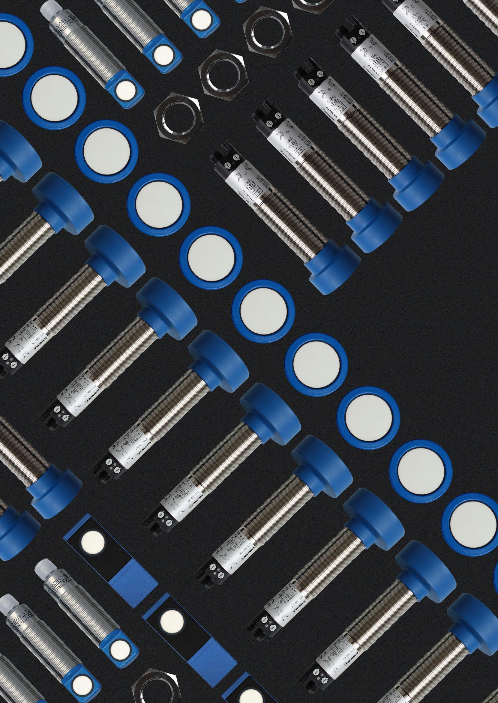
201HIGHLIGHTSSENSORSULTRASONICWWW.CONTRINEX.COM 9 Detection independent of target material, color, shape or surface 9 Ready-to-use cylindrical sensors with integral connector 9 Easy adjustment by either potentiometer or teach-in 9 Dual output sensors, including analog and digital 9 High resolution analog output, current or voltage 9 Normal length or short housings 9 Reduced blind zone 9 High excess gain, insensitive to dirt and ambient noise

Level
INDUSTRIES
Logistics systems
Diffuse ultrasonic sensor provides continuous measurement of fill level for water-tank control system Within a water-supply system, the fill level of a tank must be monitored to ensure a continuous supply of water at a constant pressure. A cost-effective solution is to mount a single diffuse-type ultrasonic sensor in the cover of the tank, where it can provide the control system with con stant measurement of the water level. Depending on this information, the control system switches the inlet pump on or off, adjusts its motor speed, and opens or closes the outlet valve. monitoring in plastic production level sensing in food industry Packaging, logistics, materials handling, food and beverage, agriculture, filling machines Brewery production equipment
APPLICATION
Liquid


Ultrasonic sensors provide reliable, non-contact detection of solid, liquid, granular or powdered materials in air. They emit a highfrequency acoustic signal in the direction of the target and evaluate the reflected signal. The target is detected and, simultaneously, its distance from the sensor can be calculated precisely from the signal’s transit time. The target material may be transparent or colored and may have a polished or matt surface. PRODUCT ACCESSORIESOVERVIEW Go to page 298 to see all the accessories Cables Mounting brackets KEY ADVANTAGES 9 Precise control of position, distance, height and level 9 Sensing ranges up to 6,000 mm 9 Range setting and NO/NC configuration by teach button or wire 9 Diffuse types with foreground and background suppression 9 Reflex types with no blind zone 9 Robust housings in food-grade stainless steel or plastic with integral M12 connector, IP67 9 M18 in standard or short body 9 M30 in standard body or with large head 9 Various output types, including analog, voltage and current 9 Crosstalk prevention through synchronization and multi plexing mode 9 Insensitive to dirt and ambient noise 9 Temperature range −20 +70°C (−4 +158°F) ULTRASONIC SENSORS IDEAL FOR LIQUID OR GRANULAR TARGETS SERIES Housing size mm M18 short body* M18 standard body* M30 standard body* M30 large head** snmm Diffuse 300 / 1,200 900 / 2,000 2,500 / 3,500 6,000 Reflex 300 / 1,200 900 / 2,000 *Metal or plastic housing **Plastic housing


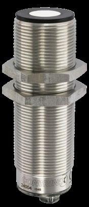
ULTRASONIC SENSORS M18 CABLES Cable lengths available: 2 m, 5 m, 10 m other customised lengths possible A Group A: M8 3-pin Sub-group: Field attachable connectors Sub-group: Distribution boxes B Group B: M8 4-pin Sub-group: Field attachable connectors C Group C: M12 4-pin Sub-group: Field attachable connectors Sub-group: Distribution boxes D Group D: M12 AC/DC 3-pin E Group E: Universal mounting brackets Sub-group: Mechanical stops F Group F: Photoelectric mounting brackets G Group G: Photoelectric reflectors H Group H: Sensor tester Go to page 298 for details ACCESSORIES OPERATINGPRINCIPLE OPERATING RANGE (mm) HOUSINGSIZE(mm) PRODUCTRANGEFAMILYSMALLM18 204 SMALLULTRASONIC M18 Diffuse Reflex OPERATING PRINCIPLE Supply Voltage range 15 30 VDC Output PNP* * Other types available: NPN COMMON FEATURES OUTPUT US[x]-[xxx][x][x]-[xxx]-[xxx] Housing size [M18] M18 [M30] M30 see p. 210 see p. 210 Sensor type [R] Reflex [T] Diffuse Housing material [M] Metal [P] Plastic Reference key on page 210 see p. 210 We made these pages with care, but we decline liability for any errors or omissions. 300 M18 Short body 1,200 M18 Short body 300 M18 Short body 1,200 M18 Short body 300 M18 Short body 1,200 M18 Short body 300 M18 Short body 1,200 M18 Short body 900 M18 Standard body 2,000 M18 Standard body 900 M18 Standard body 2,000 M18 Standard body 900 M18 Standard body 2,000 M18 Standard body 900 M18 Standard body 2,000 M18 Standard body 900 M18 Standard body 2,000 M18 Standard body 900 M18 Standard body 2,000 M18 Standard body 900 M18 Standard body 2,000 M18 Standard body 900 M18 Standard body

MATERIALHOUSING CONNECTOR FREQUENCYSWITCHING(Hz) OUTPUT 1 OUTPUT 2 OUTPUT 3 PART REFERENCE * (SEEACCESSORIESPAGE204) VIEW DATASHEETSULTRASONIC www.contrinex.com/collections/ultrasonic-sensors Detailed data sheets for these products can be found on the Contrinex website: 205WWW.CONTRINEX.COM KEY ADVANTAGES 9 Precise control of position, distance, height and level 9 Sensing ranges up to 6,000 mm 9 Range setting and NO/NC configuration by teach button or wire 9 Various output types, including analog, voltage and current 9 Diffuse types with foreground and back ground suppression 9 Reflex types with no blind zone 9 Robust housings in food-grade stain less steel or plastic with integral M12 connector, IP67 9 M18 in standard or short body 9 M30 in standard body or with large head 9 Crosstalk prevention through synchro nization and multiplexing mode 9 Insensitive to dirt and ambient noise 9 Temperature range −20 +70°C (−4 +158°F) ULTRASONIC M18 PBTP 8 NO (default)/NC UST-M18PC-WSS-303 CEH PBTP 5 NO (default)/NC UST-M18PC-WMS-303 CEH PBTP 8 NO (default)/NC USR-M18PC-WSS-303 CEH PBTP 3 NO (default)/NC USR-M18PC-WMS-303 CEH Stainless steel V2A 8 NO (default)/NC UST-M18MC-WSS-303 CEH Stainless steel V2A 5 NO (default)/NC UST-M18MC-WMS-303 CEH Stainless steel V2A 8 NO (default)/NC USR-M18MC-WSS-303 CEH Stainless steel V2A 3 NO (default)/NC USR-M18MC-WMS-303 CEH PBTP 4 NO (default)/NC UST-M18PS-TMS-403 CEH PBTP 2 NO (default)/NC UST-M18PS-TLS-403 CEH PBTP 4 NO (default)/NC NO (default)/NC UST-M18PS-TMS-603 CEH PBTP 2 NO (default)/NC NO (default)/NC UST-M18PS-TLS-603 CEH PBTP 4 NO (default)/NC NO (default)/NC 4 20 mA UST-M18PS-TMS-839 EH PBTP 2 NO (default)/NC NO (default)/NC 4 … 20 mA UST-M18PS-TLS-839 EH PBTP 4 NO (default)/NC NO (default)/NC 0 10 V UST-M18PS-TMS-83A EH PBTP 2 NO (default)/NC NO (default)/NC 0 10 V UST-M18PS-TLS-83A EH PBTP 4 NO (default)/NC NO (default)/NC SYNC/MUX UST-M18PS-TMS-813 EH PBTP 2 NO (default)/NC NO (default)/NC SYNC/MUX UST-M18PS-TLS-813 EH PBTP 4 NO (default)/NC USR-M18PS-TMS-403 CEH PBTP 2 NO (default)/NC USR-M18PS-TLS-403 CEH Stainless steel V2A 4 NO (default)/NC UST-M18MS-TMS-403 CEH Stainless steel V2A 2 NO (default)/NC UST-M18MS-TLS-403 CEH Stainless steel V2A 4 NO (default)/NC NO (default)/NC UST-M18MS-TMS-603 CEH
ULTRASONIC SENSORS M18, M30 CABLES Cable lengths available: 2 m, 5 m, 10 m other customised lengths possible OPERATINGPRINCIPLE OPERATING RANGE (mm) HOUSINGSIZE(mm) PRODUCTRANGEFAMILYSMALLM18COMPACTM30 206 SMALLULTRASONIC COMPACTM18M30Supply Voltage range 15 30 VDC Output PNP* * Other types available: NPN COMMON FEATURES A Group A: M8 3-pin Sub-group: Field attachable connectors Sub-group: Distribution boxes B Group B: M8 4-pin Sub-group: Field attachable connectors C Group C: M12 4-pin Sub-group: Field attachable connectors Sub-group: Distribution boxes D Group D: M12 AC/DC 3-pin E Group E: Universal mounting brackets Sub-group: Mechanical stops F Group F: Photoelectric mounting brackets G Group G: Photoelectric reflectors H Group H: Sensor tester Go to page 298 for details ACCESSORIES Diffuse Reflex OPERATING PRINCIPLE OUTPUT US[x]-[xxx][x][x]-[xxx]-[xxx] Housing size [M18] M18 [M30] M30 see p. 210 see p. 210 Sensor type [R] Reflex [T] Diffuse Housing material [M] Metal [P] Plastic Reference key on page 210 see p. 210 We made these pages with care, but we decline liability for any errors or omissions. 2,000 M18 Standard body 900 M18 Standard body 2,000 M18 Standard body 900 M18 Standard body 2,000 M18 Standard body 900 M18 Standard body 2,000 M18 Standard body 900 M18 Standard body 2,000 M18 Standard body 2,500 M30 Standard body 2,500 M30 Standard body 2,500 M30 Standard body 2,500 M30 Standard body 2,500 M30 Standard body 3,500 M30 Standard body 3,500 M30 Standard body 3,500 M30 Standard body 3,500 M30 Standard body 3,500 M30 Standard body 2,500 M30 Standard body 2,500 M30 Standard body 2,500 M30 Standard body
MATERIALHOUSING CONNECTOR FREQUENCYSWITCHING(Hz) OUTPUT 1 OUTPUT 2 OUTPUT 3 PART REFERENCE * (SEEACCESSORIESPAGE206) Detailed data sheets for these products can be found on the Contrinex website: 207WWW.CONTRINEX.COM KEY ADVANTAGES 9 Precise control of position, distance, height and level 9 Sensing ranges up to 6,000 mm 9 Range setting and NO/NC configuration by teach button or wire 9 Various output types, including analog, voltage and current 9 Diffuse types with foreground and back ground suppression 9 Reflex types with no blind zone 9 Robust housings in food-grade stain less steel or plastic with integral M12 connector, IP67 9 M18 in standard or short body 9 M30 in standard body or with large head 9 Crosstalk prevention through synchro nization and multiplexing mode 9 Insensitive to dirt and ambient noise 9 Temperature range −20 +70°C (−4 +158°F) ULTRASONIC M30M18,VIEW DATASHEETSULTRASONIC www.contrinex.com/collections/ultrasonic-sensors Stainless steel V2A 2 NO (default)/NC NO (default)/NC UST-M18MS-TLS-603 CEH Stainless steel V2A 4 NO (default)/NC NO (default)/NC 4 20 mA UST-M18MS-TMS-839 EH Stainless steel V2A 2 NO (default)/NC NO (default)/NC 4 20 mA UST-M18MS-TLS-839 EH Stainless steel V2A 4 NO (default)/NC NO (default)/NC 0 10 V UST-M18MS-TMS-83A EH Stainless steel V2A 2 NO (default)/NC NO (default)/NC 0 … 10 V UST-M18MS-TLS-83A EH Stainless steel V2A 4 NO (default)/NC NO (default)/NC SYNC/MUX UST-M18MS-TMS-813 EH Stainless steel V2A 2 NO (default)/NC NO (default)/NC SYNC/MUX UST-M18MS-TLS-813 EH Stainless steel V2A 4 NO (default)/NC USR-M18MS-TMS-403 CEH Stainless steel V2A 2 NO (default)/NC USR-M18MS-TLS-403 CEH PBTP 2 NO (default)/NC UST-M30PS-TMS-403 CEH PBTP 2 NO (default)/NC NO (default)/NC UST-M30PS-TMS-603 CEH PBTP 2 NO (default)/NC NO (default)/NC 4 20 mA UST-M30PS-TMS-839 EH PBTP 2 NO (default)/NC NO (default)/NC 0 … 10 V UST-M30PS-TMS-83A EH PBTP 2 NO (default)/NC NO (default)/NC SYNC/MUX UST-M30PS-TMS-813 EH PBTP 2 NO (default)/NC UST-M30PS-TLS-403 CEH PBTP 2 NO (default)/NC NO (default)/NC UST-M30PS-TLS-603 CEH PBTP 2 NO (default)/NC NO (default)/NC 4 … 20 mA UST-M30PS-TLS-839 EH PBTP 2 NO (default)/NC NO (default)/NC 0 10 V UST-M30PS-TLS-83A EH PBTP 2 NO (default)/NC NO (default)/NC SYNC/MUX UST-M30PS-TLS-813 EH Stainless steel V2A 2 NO (default)/NC UST-M30MS-TMS-403 CEH Stainless steel V2A 2 NO (default)/NC NO (default)/NC UST-M30MS-TMS-603 CEH Stainless steel V2A 2 NO (default)/NC NO (default)/NC 4 20 mA UST-M30MS-TMS-839 EH
ULTRASONIC SENSORS M30 CABLES Cable lengths available: 2 m, 5 m, 10 m other customised lengths possible OPERATINGPRINCIPLE OPERATING RANGE (mm) HOUSINGSIZE(mm) PRODUCTRANGEFAMILYCOMPACTM30 208 COMPACTULTRASONIC M30Supply Voltage range 15 30 VDC Output PNP* * Other types available: NPN COMMON FEATURES A Group A: M8 3-pin Sub-group: Field attachable connectors Sub-group: Distribution boxes B Group B: M8 4-pin Sub-group: Field attachable connectors C Group C: M12 4-pin Sub-group: Field attachable connectors Sub-group: Distribution boxes D Group D: M12 AC/DC 3-pin E Group E: Universal mounting brackets Sub-group: Mechanical stops F Group F: Photoelectric mounting brackets G Group G: Photoelectric reflectors H Group H: Sensor tester Go to page 298 for details ACCESSORIES Diffuse Reflex OPERATING PRINCIPLE OUTPUT US[x]-[xxx][x][x]-[xxx]-[xxx] Housing size [M18] M18 [M30] M30 see p. 210 see p. 210 Sensor type [R] Reflex [T] Diffuse Housing material [M] Metal [P] Plastic Reference key on page 210 see p. 210 We made these pages with care, but we decline liability for any errors or omissions. 2,500 M30 Standard body 2,500 M30 Standard body 3,500 M30 Standard body 3,500 M30 Standard body 3,500 M30 Standard body 3,500 M30 Standard body 3,500 M30 Standard body 6,000 M30 Large head 6,000 M30 Large head 6,000 M30 Large head 6,000 M30 Large head 6,000 M30 Large head

MATERIALHOUSING CONNECTOR FREQUENCYSWITCHING(Hz) OUTPUT 1 OUTPUT 2 OUTPUT 3 PART REFERENCE * (SEEACCESSORIESPAGE208) Detailed data sheets for these products can be found on the Contrinex website: 209WWW.CONTRINEX.COM KEY ADVANTAGES 9 Precise control of position, distance, height and level 9 Sensing ranges up to 6,000 mm 9 Range setting and NO/NC configuration by teach button or wire 9 Various output types, including analog, voltage and current 9 Diffuse types with foreground and back ground suppression 9 Reflex types with no blind zone 9 Robust housings in food-grade stain less steel or plastic with integral M12 connector, IP67 9 M18 in standard or short body 9 M30 in standard body or with large head 9 Crosstalk prevention through synchro nization and multiplexing mode 9 Insensitive to dirt and ambient noise 9 Temperature range −20 +70°C (−4 +158°F) ULTRASONIC M30 VIEW DATASHEETSULTRASONIC www.contrinex.com/collections/ultrasonic-sensors Stainless steel V2A 2 NO (default)/NC NO (default)/NC 0 … 10 V UST-M30MS-TMS-83A EH Stainless steel V2A 2 NO (default)/NC NO (default)/NC SYNC/MUX UST-M30MS-TMS-813 EH Stainless steel V2A 2 NO (default)/NC UST-M30MS-TLS-403 CEH Stainless steel V2A 2 NO (default)/NC NO (default)/NC UST-M30MS-TLS-603 CEH Stainless steel V2A 2 NO (default)/NC NO (default)/NC 4 … 20 mA UST-M30MS-TLS-839 EH Stainless steel V2A 2 NO (default)/NC NO (default)/NC 0 10 V UST-M30MS-TLS-83A EH Stainless steel V2A 2 NO (default)/NC NO (default)/NC SYNC/MUX UST-M30MS-TLS-813 EH PBTP 1 NO (default)/NC UST-M30PO-TXS-403 CEH PBTP 1 NO (default)/NC NO (default)/NC UST-M30PO-TXS-603 CEH PBTP 1 NO (default)/NC NO (default)/NC 4 20 mA UST-M30PO-TXS-839 EH PBTP 1 NO (default)/NC NO (default)/NC 0 10 V UST-M30PO-TXS-83A EH PBTP 1 NO (default)/NC NO (default)/NC SYNC/MUX UST-M30PO-TXS-813 EH

Detailed data sheets for these products can be found on the Contrinex website:210 ULTRASONIC SENSORS REFERENCE KEY UST-M18PS-TMS-403 SENSOR TYPE Reflex R Diffuse T HOUSING TYPE Cylindrical threaded M ULTRASONIC SENSOR US HOUSING SIZE OUTPUT NPN 01 PNP 03 4 20 mA 09 0 10 V 0A NPN + SYNC/MUX 11 PNP+ SYNC/MUX 13 NPN + 4 20 mA 29 PNP + 4 20 mA 39 NPN + 0 10 V 2A PNP + 0 10 V 3A Device 2 outputs 1 Device 1 output 3 Device 1 output with IO-Link 4 Device 2 outputs with IO-Link 6 Device 3 outputs 7 Device 3 outputs with IO-Link 8 Connector S CONNECTION TYPE Short S Standard M Long L Extra long X RANGE Wire Teach W Button Teach T ADJUSTMENT Short C Standard S Large head O HOUSING FORM ∅ 18 mm 18 ∅ 30 mm 30 HOUSING MATERIAL Metal M Plastic P
211WWW.CONTRINEX.COM REFERENCE KEY VIEW DATASHEETSULTRASONIC www.contrinex.com/collections/ultrasonic-sensors

SAFETINEXLIGHTCURTAINHIGHLIGHTS 9 Finger-, hand- and body-access resolutions 9 Operating range from 0.25 … 50 m 9 Protective heights from 142 … 1827 mm 9 Category 2 or 4 according to EN/ISO 13849-1 9 Certified TÜV, CE and UL 9 IP65 and IP67 9 Permanent autocontrol 9 2 channel selection 9 Low power consumption NEW 9 Slim Type 2 safety light curtains 9 Slim Type 4 safety light curtains with wireless configuration via Bluetooth® 9 Magnetic and RFID safety sensors 9 Signal filter SAFETY LIGHT CURTAINS, SAFETY SENSORS AND RELAYS

Detailed data sheets for these products can be found on the Contrinex website:214 PROGRAM OVERVIEW PRODUCT RANGE RESOLUTION CATEGORY FEATURES CURTAINSLIGHT SLIMBASIC 30 mm Cat. 2 9 No blind zone 9 Flexible mounting and connection STANDARDBASIC 14 mm Cat. 4 9 Maximum operating range 3.5 m 9 Operating temperature −35 +60°C 9 IP65, IP67 30 mm Cat. 4 9 Maximum operating range 12 m 9 Operating temperature −35 … +60°C 9 IP65, IP67 Cat. 2 9 Maximum operating range 12 m 9 Operating temperature 0 +50°C 9 IP65, IP67 300 mm 400 mm 500 mm Cat. 4 9 Maximum operating range 50 m 9 Operating temperature −35 +60°C 9 IP65, IP67 SLIMEXTENDED 30 mm Cat. 4 9 No blind zone 9 Beam coding (3 channels), EDM, start and restart interlock configurable functions 9 Wireless configuration via Bluetooth® 14 mm Cat. 4 9 No blind zone 9 Beam coding (3 channels), EDM, start and restart interlock configurable functions 9 Wireless configuration via Bluetooth® SAFETY SENSORS MAGNETIC up to Cat. 4 9 Magnetically coded, ISO 14119 type 4 9 Detection through metal plate possible 9 IP6K9K, Ecolab RFID Cat. 4 9 RFID coded, ISO 14119 type 4 9 Cascadable up to 30 units 9 EDM and diagnostic function
215WWW.CONTRINEX.COM SAFETY PROGRAM OVERVIEW PRODUCT RANGE FEATURES ACCESSORIES MIRROR&DEVICE COLUMNS 9 Robust protective profile, attractive design 9 Special spring elements automatically reset position in case of mechanical impact 9 Complete assembly kit for both device and floor mounting included 9 Easy to mount: vertical and axial adjustments can be quickly com pleted in just a few steps 9 Single mirror or exchangeable and separately adjustable individual mirrors in accordance with EN 999 MISCELLANEOUS Relay 9 Performance Level (PL) e and category 4 according to EN/ ISO 13849-1 9 Manual or automatic restart 9 Short response time Top/bottom mounting brackets 9 Synthetic mounting brackets 9 Pair of brackets supplied with each bracket Side/end mounting brackets 9 Metal mounting brackets Safety filter 9 Integrated RC filter for counter signal cut 9 Possibility to connect sender and receiver unit on same connector Laser alignment tool 9 Easily clippable onto Safetinex YBB and YCA devices 9 Range: up to 50 m

Beam
Detailed data sheets for these products can be found Contrinex website:216
INTRODUCTION
on the
Safetinex light curtains and access control barriers are active optoelectronic protective devices (AOPDs) that include a sender and a receiver unit between which coded infrared beams are sequentially exchanged. The receiver unit is connected to a safety relay which transmits signals to the machine control system. Synchronization between the sender and receiver devices is performed optically, i.e. wired connection between the two units is not necessary. Reception of all beams activates the two independently generated semicon ductor outputs (OSSDs) of the receiver unit. The interruption of one or more beams deactivates the outputs within the response time of the AOPD. Any internal fault is detected by the device’s permanent self-control function and has the same result as an intrusion into the protective field. separation ≥ 300 mm resolution 30 mm
OPERATING PRINCIPLE OF LIGHT CURTAINS Safetinex YBB, YBBS and YBES light curtains and YCA access control barriers operate with infrared beams. When the device detects a finger, a hand or a person entering the defined hazardous area, the protective equipment imme diately stops the machine, or renders it harmless. When operating in manual restart mode, the reset button enabling the operator to restart the machine must be located outside the hazardous area. From there, the operator must have a full view of the hazardous area to make sure that nobody is in danger before restarting the machine.
Safetinex light curtains and access control barriers are designed to ensure pro tection of operators working in hazardous areas. A high reliability is achieved by implementing a fail-safe system: devices are thus permanently self-controlled. An internal failure deactivates the output signals, as would an intrusion into the protective field.
Access control Beam
Hand protection Beam resolution 14 mm Finger protection EXTENDED SLIM – WIRELESS CONFIGURATION Download now to monitor and configure your light curtains!


217WWW.CONTRINEX.COM
Safetinex YSM and YSR safety sensors comprise two parts: a main module and an actuator. They communicate with a contactless system of either magnetic or RFID coding. When the system detects that a guard door, hood or cover is open, the protective equipment immediately stops the machine, or renders it YSMharmless.magnetic
OPERATING PRINCIPLE OF SAFETY SENSORS
safety sensors use a coded magnet as an actuator and two reed contacts to open or close communication. Unlike light curtains, these sensors do not have OSSD outputs with self-check. They act simply as contactors that open or close depending on the presence or absence of a magnet. It is therefore necessary to apply power to the reed contacts.
YSR RFID safety sensors use an RFID tag as an actuator and a read/write mod ule (RWM) as a contactor. These sensors have self-checking OSSD outputs, similar to light curtains. They are therefore connected in the same way as light curtains to a relay or controller. The RFID tag can be universally and randomly coded or can be teachable, which means the user pairs it with an RWM at first use to create a unique combination.


APPLICATION Efficient and cost-effective protection with Safetinex Type 2 During semi-automated heat staking of assemblies for domestic white goods, manufacturers use light curtains to preserve operator safety without compromising pro duction throughput. The active optoelectronic protec tive device (AOPD), mounted directly in front of each bench-mounted heat-press, prevents the press-head from descending if it detects any intrusion in the working area, halting the operating cycle immediately. INDUSTRIES Automotive production and supply, machine tool, packaging, logistics, materials handling, textile, assembly, automation, robotics Automotive industry MachineRobotics tools Textile industry


SAFETY BASICCURTAINSLIGHTEXCELLENTPRICE/PERFORMANCE RATIO Light curtains are TÜV, CE and UL-certified according to IEC 61496 1 and -2 and ISO 13849 1. Protective heights range from 142 to 1,827 mm with permanent autocontrol and low power consumption. The aluminum housings are slim (26 × 26 mm) or standard (42 × 48 mm) and connection is via an integral 5-pin M12 connector or pigtail. ACCESSORIES Go to pages 256 and 298 to see all the accessories KEY ADVANTAGES FINGER TYPE 4 9 Beam resolution 14 mm 9 Highest protection category: Type 4 9 Max. operating range 3.5 m 9 Operating temperature −35 +60°C (−31 +140°F) 9 Standard housing (42 × 48 mm) IP65, IP67 HAND TYPE 4 AND HAND TYPE 2 9 Beam resolution 30 mm 9 Two protection categories: Type 4 or Type 2 9 Standard housing (42 × 48 mm): max. operating range 12 m, operating temperature −35 +60°C (−31 +140°F), IP65, IP67 9 Slim housing (26 × 26 mm): max operating range 8 m, no blind zone, operating temperature 0 +55°C (+32 +131°F), IP65 ACCESS TYPE 4 9 Beam gap: 300, 400 or 500 mm (3 to 6 beams) 9 Highest protection category: Type 4 9 Max. operating range 1 15 m or 10 50 m (selectable) 9 Operating temperature −35 … +60°C (−31 … +140°F) 9 Standard housing (42 × 48 mm) IP65, IP67 SERIES Type FINGER 4 HAND 4 / 2 ACCESS 4 PROTECTIVE )(HEIGHTmm Basic Standard 142 … 1,690 279 1,827 (type 4) 150 1,827 (type 2) 832 … 1,532 Basic Slim 170 1,610 PRODUCT OVERVIEW Mounting bracketsRelay


Safety Level Cat. 2, PL c, Type 2 Supply Voltage 24 VDC Polarity PNP Resolution 30 mm (hand) COMMON FEATURES Relay See page 256 Top/bottom mounting bracket For YBB & YCA See page 256 Sliding T-nuts for side mounting See page 256 Mounting bracket No. 5 For YBBS & YBES See page 256 Mounting bracket No. 6 For YBBS & YBES See page 256 Mounting bracket No. 7 For YBBS & YBES See page 256 Safety filter See page 257 Laser alignment tool See page 257 Device columns See page 254 Mirror columns See page 254 Go to page 298 for details ACCESSORIES HAND OPERATINGTYPEPROTECTION2RANGE(mm)HOUSINGSIZE(mm) FAMILYHANDPROTECTION–TYPE2 220 SAFETY LIGHT CURTAINS BASIC STANDARD OUTPUT YBB-30[x]2-[xxxx]-[xxxx] Module [K] Kit (sender + receiver) [R] Receiver [S] Sender Protective height rounded (mm) Connection type [G012] M12 connector, 5 pins Reference key on page 258 We made these pages with care, but we decline liability for any errors or omissions. 0.25 12 m 42 × 48 (standard) 0.25 12 m 42 × 48 (standard) 0.25 12 m 42 × 48 (standard) 0.25 12 m 42 × 48 (standard) 0.25 12 m 42 × 48 (standard) 0.25 12 m 42 × 48 (standard) 0.25 12 m 42 × 48 (standard) 0.25 12 m 42 × 48 (standard) 0.25 12 m 42 × 48 (standard) 0.25 12 m 42 × 48 (standard) 0.25 12 m 42 × 48 (standard) 0.25 12 m 42 × 48 (standard) 0.25 12 m 42 × 48 (standard) 0.25 12 m 42 × 48 (standard) 0.25 12 m 42 × 48 (standard) 0.25 12 m 42 × 48 (standard) 0.25 … 12 m 42 × 48 (standard) 0.25 … 12 m 42 × 48 (standard) 0.25 … 12 m 42 × 48 (standard) 0.25 … 12 m 42 × 48 (standard) 0.25 … 12 m 42 × 48 (standard) 0.25 … 12 m 42 × 48 (standard) 0.25 … 12 m 42 × 48 (standard) 0.25 … 12 m 42 × 48 (standard) 0.25 … 12 m 42 × 48 (standard) 0.25 … 12 m 42 × 48 (standard) 0.25 … 12 m 42 × 48 (standard) 0.25 … 12 m 42 × 48 (standard)


SAFETY 2TYPEVIEW DATASHEETSSAFETY www.contrinex.com/collections/safety-light-curtains-basic-standard KEY ADVANTAGES 9 Resolution: 30 mm 9 Operating range: 0.25 12 m 9 Protective height: 150 1,827 mm 9 Category 2, PL c according to EN/ISO 13849-1 9 Type 2 according to IEC 61496-1 and -2 9 Certified TÜV, CE 9 Housing profile 42 × 48 mm PROTECTIVEHEIGHT(mm) HEIGHTTOTAL(mm) WAVELENGTHSENDER(nm) RESPONSETIME(ms) BEAM GAP (mm) OFNUMBERBEAMS TEMPERATUREAMBIENT PROTECTIONDEGREEOF PART REFERENCE Detailed data sheets for these products can be found on the Contrinex website: 221WWW.CONTRINEX.COM 150 251 IR 850 14 16 9 0 +50°C IP65 / IP67 YBB-30K2-0150-G012 279 380 IR 850 18 16 17 0 +50°C IP65 / IP67 YBB-30K2-0250-G012 408 509 IR 850 22 16 25 0 +50°C IP65 / IP67 YBB-30K2-0400-G012 537 638 IR 850 26 16 33 0 +50°C IP65 / IP67 YBB-30K2-0500-G012 666 767 IR 850 30 16 41 0 +50°C IP65 / IP67 YBB-30K2-0700-G012 795 896 IR 850 34 16 49 0 +50°C IP65 / IP67 YBB-30K2-0800-G012 924 1,025 IR 850 38 16 57 0 +50°C IP65 / IP67 YBB-30K2-0900-G012 1,053 1,154 IR 850 42 16 65 0 +50°C IP65 / IP67 YBB-30K2-1000-G012 1,182 1,283 IR 850 46 16 73 0 +50°C IP65 / IP67 YBB-30K2-1200-G012 1,311 1,412 IR 850 50 16 81 0 +50°C IP65 / IP67 YBB-30K2-1300-G012 1,440 1,541 IR 850 54 16 89 0 +50°C IP65 / IP67 YBB-30K2-1400-G012 1,569 1,670 IR 850 58 16 97 0 +50°C IP65 / IP67 YBB-30K2-1600-G012 1,698 1,799 IR 850 62 16 105 0 +50°C IP65 / IP67 YBB-30K2-1700-G012 1,827 1,928 IR 850 66 16 113 0 +50°C IP65 / IP67 YBB-30K2-1800-G012 150 251 IR 850 14 16 9 0 +50°C IP65 / IP67 YBB-30S2-0150-G012 279 380 IR 850 18 16 17 0 +50°C IP65 / IP67 YBB-30S2-0250-G012 408 509 IR 850 22 16 25 0 +50°C IP65 / IP67 YBB-30S2-0400-G012 537 638 IR 850 26 16 33 0 +50°C IP65 / IP67 YBB-30S2-0500-G012 666 767 IR 850 30 16 41 0 +50°C IP65 / IP67 YBB-30S2-0700-G012 795 896 IR 850 34 16 49 0 +50°C IP65 / IP67 YBB-30S2-0800-G012 924 1,025 IR 850 38 16 57 0 +50°C IP65 / IP67 YBB-30S2-0900-G012 1,053 1,154 IR 850 42 16 65 0 +50°C IP65 / IP67 YBB-30S2-1000-G012 1,182 1,283 IR 850 46 16 73 0 +50°C IP65 / IP67 YBB-30S2-1200-G012 1,311 1,412 IR 850 50 16 81 0 +50°C IP65 / IP67 YBB-30S2-1300-G012 1,440 1,541 IR 850 54 16 89 0 +50°C IP65 / IP67 YBB-30S2-1400-G012 1,569 1,670 IR 850 58 16 97 0 +50°C IP65 / IP67 YBB-30S2-1600-G012 1,698 1,799 IR 850 62 16 105 0 +50°C IP65 / IP67 YBB-30S2-1700-G012 1,827 1,928 IR 850 66 16 113 0 +50°C IP65 / IP67 YBB-30S2-1800-G012
Safety Level Cat. 2, PL c, Type 2 Supply Voltage 24 VDC Polarity PNP Resolution 30 mm (hand) COMMON FEATURES Relay See page 256 Top/bottom mounting bracket For YBB & YCA See page 256 Sliding T-nuts for side mounting See page 256 Mounting bracket No. 5 For YBBS & YBES See page 256 Mounting bracket No. 6 For YBBS & YBES See page 256 Mounting bracket No. 7 For YBBS & YBES See page 256 Safety filter See page 257 Laser alignment tool See page 257 Device columns See page 254 Mirror columns See page 254 Go to page 298 for details ACCESSORIES HAND OPERATINGTYPEPROTECTION2RANGE(mm)HOUSINGSIZE(mm) FAMILYHANDPROTECTION–TYPE2 222 SAFETY LIGHT CURTAINS BASIC STANDARD OUTPUT YBB-30[x]2-[xxxx]-[xxxx] Module [K] Kit (sender + receiver) [R] Receiver [S] Sender Protective height rounded (mm) Connection type [G012] M12 connector, 5 pins Reference key on page 258 We made these pages with care, but we decline liability for any errors or omissions. 0.25 12 m 42 × 48 (standard) 0.25 12 m 42 × 48 (standard) 0.25 12 m 42 × 48 (standard) 0.25 12 m 42 × 48 (standard) 0.25 12 m 42 × 48 (standard) 0.25 12 m 42 × 48 (standard) 0.25 12 m 42 × 48 (standard) 0.25 12 m 42 × 48 (standard) 0.25 12 m 42 × 48 (standard) 0.25 12 m 42 × 48 (standard) 0.25 12 m 42 × 48 (standard) 0.25 12 m 42 × 48 (standard) 0.25 12 m 42 × 48 (standard) 0.25 12 m 42 × 48 (standard)

SAFETY 2TYPEVIEW DATASHEETSSAFETY www.contrinex.com/collections/safety-light-curtains-basic-standard KEY ADVANTAGES 9 Resolution: 30 mm 9 Operating range: 0.25 12 m 9 Protective height: 150 1,827 mm 9 Category 2, PL c according to EN/ISO 13849-1 9 Type 2 according to IEC 61496-1 and -2 9 Certified TÜV, CE 9 Housing profile 42 × 48 mm PROTECTIVEHEIGHT(mm) HEIGHTTOTAL(mm) WAVELENGTHSENDER(nm) RESPONSETIME(ms) BEAM GAP (mm) OFNUMBERBEAMS TEMPERATUREAMBIENT PROTECTIONDEGREEOF PART REFERENCE Detailed data sheets for these products can be found on the Contrinex website: 223WWW.CONTRINEX.COM 150 251 IR 850 14 16 9 0 +50°C IP65 / IP67 YBB-30R2-0150-G012 279 380 IR 850 18 16 17 0 +50°C IP65 / IP67 YBB-30R2-0250-G012 408 509 IR 850 22 16 25 0 +50°C IP65 / IP67 YBB-30R2-0400-G012 537 638 IR 850 26 16 33 0 +50°C IP65 / IP67 YBB-30R2-0500-G012 666 767 IR 850 30 16 41 0 +50°C IP65 / IP67 YBB-30R2-0700-G012 795 896 IR 850 34 16 49 0 +50°C IP65 / IP67 YBB-30R2-0800-G012 924 1,025 IR 850 38 16 57 0 +50°C IP65 / IP67 YBB-30R2-0900-G012 1,053 1,154 IR 850 42 16 65 0 +50°C IP65 / IP67 YBB-30R2-1000-G012 1,182 1,283 IR 850 46 16 73 0 +50°C IP65 / IP67 YBB-30R2-1200-G012 1,311 1,412 IR 850 50 16 81 0 +50°C IP65 / IP67 YBB-30R2-1300-G012 1,440 1,541 IR 850 54 16 89 0 +50°C IP65 / IP67 YBB-30R2-1400-G012 1,569 1,670 IR 850 58 16 97 0 +50°C IP65 / IP67 YBB-30R2-1600-G012 1,698 1,799 IR 850 62 16 105 0 +50°C IP65 / IP67 YBB-30R2-1700-G012 1,827 1,928 IR 850 66 16 113 0 +50°C IP65 / IP67 YBB-30R2-1800-G012

Safety Level Cat. 4, PL e, Type 4 Supply Voltage 24 VDC Polarity PNP Resolution 30 mm (hand) COMMON FEATURES Relay See page 256 Top/bottom mounting bracket For YBB & YCA See page 256 Sliding T-nuts for side mounting See page 256 Mounting bracket No. 5 For YBBS & YBES See page 256 Mounting bracket No. 6 For YBBS & YBES See page 256 Mounting bracket No. 7 For YBBS & YBES See page 256 Safety filter See page 257 Laser alignment tool See page 257 Device columns See page 254 Mirror columns See page 254 Go to page 298 for details ACCESSORIES HAND TYPEPROTECTION4 FAMILYHANDPROTECTION–TYPE4 224 OPERATING RANGE (mm) HOUSING SIZE (mm) SAFETY LIGHT CURTAINS BASIC STANDARD OUTPUT YBB-30[x]4-[xxxx]-[xxxx] Module [K] Kit (sender + receiver) [R] Receiver [S] Sender Protective height rounded (mm) Connection type [G012] M12 connector, 5 pins Reference key on page 258 We made these pages with care, but we decline liability for any errors or omissions. 0.25 12 m 42 × 48 (standard) 0.25 12 m 42 × 48 (standard) 0.25 12 m 42 × 48 (standard) 0.25 12 m 42 × 48 (standard) 0.25 12 m 42 × 48 (standard) 0.25 12 m 42 × 48 (standard) 0.25 12 m 42 × 48 (standard) 0.25 12 m 42 × 48 (standard) 0.25 12 m 42 × 48 (standard) 0.25 12 m 42 × 48 (standard) 0.25 12 m 42 × 48 (standard) 0.25 12 m 42 × 48 (standard) 0.25 12 m 42 × 48 (standard) 0.25 12 m 42 × 48 (standard) 0.25 12 m 42 × 48 (standard) 0.25 12 m 42 × 48 (standard) 0.25 … 12 m 42 × 48 (standard) 0.25 … 12 m 42 × 48 (standard) 0.25 … 12 m 42 × 48 (standard) 0.25 … 12 m 42 × 48 (standard) 0.25 … 12 m 42 × 48 (standard) 0.25 … 12 m 42 × 48 (standard) 0.25 … 12 m 42 × 48 (standard) 0.25 … 12 m 42 × 48 (standard) 0.25 … 12 m 42 × 48 (standard) 0.25 … 12 m 42 × 48 (standard) 0.25 … 12 m 42 × 48 (standard) 0.25 … 12 m 42 × 48 (standard)
SAFETY 4TYPE KEY ADVANTAGES 9 Resolution: 30 mm 9 Operating range: 0.25 12 m 9 Protective height: 279 1,827 mm 9 Category 4, PL e according to EN/ISO 13849-1 9 Type 4 according to IEC 61496-1 and -2 9 Certified TÜV, CE and UL 9 IP65, IP67 with operating temperatures as low as −35°C (−31°F) Detailed data sheets for these products can be found on the Contrinex website: 225WWW.CONTRINEX.COM 9 Housing profile 42 × 48 mm 9 2-channel selection 9 Optical synchronization 9 Permanent autocontrol PROTECTIVEHEIGHT(mm) HEIGHTTOTAL(mm) WAVELENGTHSENDER(nm) RESPONSETIME(ms) BEAM GAP (mm) OFNUMBERBEAMS TEMPERATUREAMBIENT PROTECTIONDEGREEOF PART REFERENCE VIEW DATASHEETSSAFETY www.contrinex.com/collections/safety-light-curtains-basic-standard 279 380 IR 880 5.2 16 17 −35 +60°C IP65 / IP67 YBB-30K4-0250-G012 408 509 IR 880 6.8 16 25 −35 +60°C IP65 / IP67 YBB-30K4-0400-G012 537 638 IR 880 8.4 16 33 −35 +60°C IP65 / IP67 YBB-30K4-0500-G012 666 767 IR 880 10 16 41 −35 +60°C IP65 / IP67 YBB-30K4-0700-G012 795 896 IR 880 11.6 16 49 −35 +60°C IP65 / IP67 YBB-30K4-0800-G012 924 1,025 IR 880 13.2 16 57 −35 +60°C IP65 / IP67 YBB-30K4-0900-G012 1,053 1,154 IR 880 14.8 16 65 −35 +60°C IP65 / IP67 YBB-30K4-1000-G012 1,182 1,283 IR 880 16.4 16 73 −35 +60°C IP65 / IP67 YBB-30K4-1200-G012 1,311 1,412 IR 880 18 16 81 −35 +60°C IP65 / IP67 YBB-30K4-1300-G012 1,440 1,541 IR 880 19.6 16 89 −35 +60°C IP65 / IP67 YBB-30K4-1400-G012 1,569 1,670 IR 880 21.2 16 97 −35 +60°C IP65 / IP67 YBB-30K4-1600-G012 1,698 1,799 IR 880 22.8 16 105 −35 +60°C IP65 / IP67 YBB-30K4-1700-G012 1,827 1,928 IR 880 24.4 16 113 −35 +60°C IP65 / IP67 YBB-30K4-1800-G012 279 380 IR 880 5.2 16 17 −35 +60°C IP65 / IP67 YBB-30S4-0250-G012 408 509 IR 880 6.8 16 25 −35 +60°C IP65 / IP67 YBB-30S4-0400-G012 537 638 IR 880 8.4 16 33 −35 +60°C IP65 / IP67 YBB-30S4-0500-G012 666 767 IR 880 10 16 41 −35 +60°C IP65 / IP67 YBB-30S4-0700-G012 795 896 IR 880 11.6 16 49 −35 +60°C IP65 / IP67 YBB-30S4-0800-G012 924 1,025 IR 880 13.2 16 57 −35 +60°C IP65 / IP67 YBB-30S4-0900-G012 1,053 1,154 IR 880 14.8 16 65 −35 +60°C IP65 / IP67 YBB-30S4-1000-G012 1,182 1,283 IR 880 16.4 16 73 −35 +60°C IP65 / IP67 YBB-30S4-1200-G012 1,311 1,412 IR 880 18 16 81 −35 +60°C IP65 / IP67 YBB-30S4-1300-G012 1,440 1,541 IR 880 19.6 16 89 −35 +60°C IP65 / IP67 YBB-30S4-1400-G012 1,569 1,670 IR 880 21.2 16 97 −35 +60°C IP65 / IP67 YBB-30S4-1600-G012 1,698 1,799 IR 880 22.8 16 105 −35 +60°C IP65 / IP67 YBB-30S4-1700-G012 1,827 1,928 IR 880 24.4 16 113 −35 +60°C IP65 / IP67 YBB-30S4-1800-G012 279 380 IR 880 5.2 16 17 −35 +60°C IP65 / IP67 YBB-30R4-0250-G012 408 509 IR 880 6.8 16 25 −35 +60°C IP65 / IP67 YBB-30R4-0400-G012
Safety Level Cat. 4, PL e, Type 4 Supply Voltage 24 VDC Polarity PNP Resolution 30 mm (hand) COMMON FEATURES Relay See page 256 Top/bottom mounting bracket For YBB & YCA See page 256 Sliding T-nuts for side mounting See page 256 Mounting bracket No. 5 For YBBS & YBES See page 256 Mounting bracket No. 6 For YBBS & YBES See page 256 Mounting bracket No. 7 For YBBS & YBES See page 256 Safety filter See page 257 Laser alignment tool See page 257 Device columns See page 254 Mirror columns See page 254 Go to page 298 for details ACCESSORIES HAND TYPEPROTECTION4 FAMILYHANDPROTECTION–TYPE4 226 OPERATING RANGE (mm) HOUSING SIZE (mm) SAFETY LIGHT CURTAINS BASIC STANDARD OUTPUT YBB-30[x]4-[xxxx]-[xxxx] Module [K] Kit (sender + receiver) [R] Receiver [S] Sender Protective height rounded (mm) Connection type [G012] M12 connector, 5 pins Reference key on page 258 We made these pages with care, but we decline liability for any errors or omissions. 0.25 12 m 42 × 48 (standard) 0.25 12 m 42 × 48 (standard) 0.25 12 m 42 × 48 (standard) 0.25 12 m 42 × 48 (standard) 0.25 12 m 42 × 48 (standard) 0.25 12 m 42 × 48 (standard) 0.25 12 m 42 × 48 (standard) 0.25 12 m 42 × 48 (standard) 0.25 12 m 42 × 48 (standard) 0.25 12 m 42 × 48 (standard) 0.25 12 m 42 × 48 (standard)

SAFETY 4TYPE KEY ADVANTAGES 9 Resolution: 30 mm 9 Operating range: 0.25 12 m 9 Protective height: 279 1,827 mm 9 Category 4, PL e according to EN/ISO 13849-1 9 Type 4 according to IEC 61496-1 and -2 9 Certified TÜV, CE and UL 9 IP65, IP67 with operating temperatures as low as −35°C (−31°F) Detailed data sheets for these products can be found on the Contrinex website: 227WWW.CONTRINEX.COM 9 Housing profile 42 × 48 mm 9 2-channel selection 9 Optical synchronization 9 Permanent autocontrol PROTECTIVEHEIGHT(mm) HEIGHTTOTAL(mm) WAVELENGTHSENDER(nm) RESPONSETIME(ms) BEAM GAP (mm) OFNUMBERBEAMS TEMPERATUREAMBIENT PROTECTIONDEGREEOF PART REFERENCE VIEW DATASHEETSSAFETY www.contrinex.com/collections/safety-light-curtains-basic-standard 537 638 IR 880 8.4 16 33 −35 +60°C IP65 / IP67 YBB-30R4-0500-G012 666 767 IR 880 10 16 41 −35 +60°C IP65 / IP67 YBB-30R4-0700-G012 795 896 IR 880 11.6 16 49 −35 +60°C IP65 / IP67 YBB-30R4-0800-G012 924 1,025 IR 880 13.2 16 57 −35 +60°C IP65 / IP67 YBB-30R4-0900-G012 1,053 1,154 IR 880 14.8 16 65 −35 +60°C IP65 / IP67 YBB-30R4-1000-G012 1,182 1,283 IR 880 16.4 16 73 −35 +60°C IP65 / IP67 YBB-30R4-1200-G012 1,311 1,412 IR 880 18 16 81 −35 +60°C IP65 / IP67 YBB-30R4-1300-G012 1,440 1,541 IR 880 19.6 16 89 −35 +60°C IP65 / IP67 YBB-30R4-1400-G012 1,569 1,670 IR 880 21.2 16 97 −35 +60°C IP65 / IP67 YBB-30R4-1600-G012 1,698 1,799 IR 880 22.8 16 105 −35 +60°C IP65 / IP67 YBB-30R4-1700-G012 1,827 1,928 IR 880 24.4 16 113 −35 +60°C IP65 / IP67 YBB-30R4-1800-G012

Safety Level Cat. 4, PL e, Type 4 Supply Voltage 24 VDC Polarity PNP Resolution 14 mm (finger) COMMON FEATURES Relay See page 256 Top/bottom mounting bracket For YBB & YCA See page 256 Sliding T-nuts for side mounting See page 256 Mounting bracket No. 5 For YBBS & YBES See page 256 Mounting bracket No. 6 For YBBS & YBES See page 256 Mounting bracket No. 7 For YBBS & YBES See page 256 Safety filter See page 257 Laser alignment tool See page 257 Device columns See page 254 Mirror columns See page 254 Go to page 298 for details ACCESSORIES FINGER TYPEPROTECTION4 FAMILYFINGERPROTECTION–TYPE4 228 OPERATING RANGE (mm) HOUSING SIZE (mm) SAFETY LIGHT CURTAINS BASIC STANDARD OUTPUT YBB-14[x]4-[xxxx]-[xxxx] Module [K] Kit (sender + receiver) [R] Receiver [S] Sender Protective height rounded (mm) Connection type [G012] M12 connector, 5 pins Reference key on page 258 We made these pages with care, but we decline liability for any errors or omissions. 0.25 3.5 m 42 × 48 (standard) 0.25 3.5 m 42 × 48 (standard) 0.25 3.5 m 42 × 48 (standard) 0.25 3.5 m 42 × 48 (standard) 0.25 3.5 m 42 × 48 (standard) 0.25 3.5 m 42 × 48 (standard) 0.25 3.5 m 42 × 48 (standard) 0.25 3.5 m 42 × 48 (standard) 0.25 3.5 m 42 × 48 (standard) 0.25 3.5 m 42 × 48 (standard) 0.25 3.5 m 42 × 48 (standard) 0.25 3.5 m 42 × 48 (standard) 0.25 3.5 m 42 × 48 (standard) 0.25 3.5 m 42 × 48 (standard) 0.25 3.5 m 42 × 48 (standard) 0.25 3.5 m 42 × 48 (standard) 0.25 … 3.5 m 42 × 48 (standard) 0.25 … 3.5 m 42 × 48 (standard) 0.25 … 3.5 m 42 × 48 (standard) 0.25 … 3.5 m 42 × 48 (standard) 0.25 … 3.5 m 42 × 48 (standard) 0.25 … 3.5 m 42 × 48 (standard) 0.25 … 3.5 m 42 × 48 (standard) 0.25 … 3.5 m 42 × 48 (standard) 0.25 … 3.5 m 42 × 48 (standard) 0.25 … 3.5 m 42 × 48 (standard) 0.25 … 3.5 m 42 × 48 (standard) 0.25 … 3.5 m 42 × 48 (standard)

SAFETY 4TYPE KEY ADVANTAGES 9 Resolution: 14 mm 9 Operating range: 0.25 3.5 m 9 Protective height: 142 1,690 mm 9 Category 4, PL e according to EN/ISO 13849-1 9 Type 4 according to IEC 61496-1 and -2 9 Certified TÜV, CE and UL 9 IP65, IP67 with operating temperatures as low as −35°C (−31°F) Detailed data sheets for these products can be found on the Contrinex website: 229WWW.CONTRINEX.COM 9 Housing profile 42 × 48 mm 9 2-channel selection 9 Optical synchronization 9 Permanent autocontrol PROTECTIVEHEIGHT(mm) HEIGHTTOTAL(mm) WAVELENGTHSENDER(nm) RESPONSETIME(ms) BEAM GAP (mm) OFNUMBERBEAMS TEMPERATUREAMBIENT PROTECTIONDEGREEOF PART REFERENCE VIEW DATASHEETSSAFETY www.contrinex.com/collections/safety-light-curtains-basic-standard 142 251 IR 950 5.2 8 17 −35 +60°C IP65 / IP67 YBB-14K4-0150-G012 271 380 IR 950 8.4 8 33 −35 +60°C IP65 / IP67 YBB-14K4-0250-G012 400 509 IR 950 11.6 8 49 −35 +60°C IP65 / IP67 YBB-14K4-0400-G012 529 638 IR 950 14.8 8 65 −35 +60°C IP65 / IP67 YBB-14K4-0500-G012 658 737 IR 950 18 8 81 −35 +60°C IP65 / IP67 YBB-14K4-0700-G012 787 896 IR 950 21.2 8 97 −35 +60°C IP65 / IP67 YBB-14K4-0800-G012 916 1,025 IR 950 24.4 8 113 −35 +60°C IP65 / IP67 YBB-14K4-0900-G012 1,045 1,154 IR 950 27.6 8 129 −35 +60°C IP65 / IP67 YBB-14K4-1000-G012 1,174 1,283 IR 950 30.8 8 145 −35 +60°C IP65 / IP67 YBB-14K4-1200-G012 1,303 1,412 IR 950 34 8 161 −35 +60°C IP65 / IP67 YBB-14K4-1300-G012 1,432 1,541 IR 950 37.2 8 177 −35 +60°C IP65 / IP67 YBB-14K4-1400-G012 1,561 1,670 IR 950 40.4 8 193 −35 +60°C IP65 / IP67 YBB-14K4-1600-G012 1,690 1,799 IR 950 43.6 8 209 −35 +60°C IP65 / IP67 YBB-14K4-1700-G012 142 251 IR 950 5.2 8 17 −35 +60°C IP65 / IP67 YBB-14S4-0150-G012 271 380 IR 950 8.4 8 33 −35 +60°C IP65 / IP67 YBB-14S4-0250-G012 400 509 IR 950 11.6 8 49 −35 +60°C IP65 / IP67 YBB-14S4-0400-G012 529 638 IR 950 14.8 8 65 −35 +60°C IP65 / IP67 YBB-14S4-0500-G012 658 737 IR 950 18 8 81 −35 +60°C IP65 / IP67 YBB-14S4-0700-G012 787 896 IR 950 21.2 8 97 −35 +60°C IP65 / IP67 YBB-14S4-0800-G012 916 1,025 IR 950 24.4 8 113 −35 +60°C IP65 / IP67 YBB-14S4-0900-G012 1,045 1,154 IR 950 27.6 8 129 −35 +60°C IP65 / IP67 YBB-14S4-1000-G012 1,174 1,283 IR 950 30.8 8 145 −35 +60°C IP65 / IP67 YBB-14S4-1200-G012 1,303 1,412 IR 950 34 8 161 −35 +60°C IP65 / IP67 YBB-14S4-1300-G012 1,432 1,541 IR 950 37.2 8 177 −35 +60°C IP65 / IP67 YBB-14S4-1400-G012 1,561 1,670 IR 950 40.4 8 193 −35 +60°C IP65 / IP67 YBB-14S4-1600-G012 1,690 1,799 IR 950 43.6 8 209 −35 +60°C IP65 / IP67 YBB-14S4-1700-G012 142 251 IR 950 5.2 8 17 −35 +60°C IP65 / IP67 YBB-14R4-0150-G012 271 380 IR 950 8.4 8 33 −35 +60°C IP65 / IP67 YBB-14R4-0250-G012
Safety Level Cat. 4, PL e, Type 4 Supply Voltage 24 VDC Polarity PNP Resolution 14 mm (finger) COMMON FEATURES Relay See page 256 Top/bottom mounting bracket For YBB & YCA See page 256 Sliding T-nuts for side mounting See page 256 Mounting bracket No. 5 For YBBS & YBES See page 256 Mounting bracket No. 6 For YBBS & YBES See page 256 Mounting bracket No. 7 For YBBS & YBES See page 256 Safety filter See page 257 Laser alignment tool See page 257 Device columns See page 254 Mirror columns See page 254 Go to page 298 for details ACCESSORIES FINGER TYPEPROTECTION4 FAMILYFINGERPROTECTION–TYPE4 230 OPERATING RANGE (mm) HOUSING SIZE (mm) SAFETY LIGHT CURTAINS BASIC STANDARD OUTPUT YBB-14[x]4-[xxxx]-[xxxx] Module [K] Kit (sender + receiver) [R] Receiver [S] Sender Protective height rounded (mm) Connection type [G012] M12 connector, 5 pins Reference key on page 258 We made these pages with care, but we decline liability for any errors or omissions. 0.25 3.5 m 42 × 48 (standard) 0.25 3.5 m 42 × 48 (standard) 0.25 3.5 m 42 × 48 (standard) 0.25 3.5 m 42 × 48 (standard) 0.25 3.5 m 42 × 48 (standard) 0.25 3.5 m 42 × 48 (standard) 0.25 3.5 m 42 × 48 (standard) 0.25 3.5 m 42 × 48 (standard) 0.25 3.5 m 42 × 48 (standard) 0.25 3.5 m 42 × 48 (standard) 0.25 3.5 m 42 × 48 (standard)
SAFETY 4TYPE KEY ADVANTAGES 9 Resolution: 14 mm 9 Operating range: 0.25 3.5 m 9 Protective height: 142 1,690 mm 9 Category 4, PL e according to EN/ISO 13849-1 9 Type 4 according to IEC 61496-1 and -2 9 Certified TÜV, CE and UL 9 IP65, IP67 with operating temperatures as low as −35°C (−31°F) Detailed data sheets for these products can be found on the Contrinex website: 231WWW.CONTRINEX.COM 9 Housing profile 42 × 48 mm 9 2-channel selection 9 Optical synchronization 9 Permanent autocontrol PROTECTIVEHEIGHT(mm) HEIGHTTOTAL(mm) WAVELENGTHSENDER(nm) RESPONSETIME(ms) BEAM GAP (mm) OFNUMBERBEAMS TEMPERATUREAMBIENT PROTECTIONDEGREEOF PART REFERENCE VIEW DATASHEETSSAFETY www.contrinex.com/collections/safety-light-curtains-basic-standard 400 509 IR 950 11.6 8 49 −35 +60°C IP65 / IP67 YBB-14R4-0400-G012 529 638 IR 950 14.8 8 65 −35 +60°C IP65 / IP67 YBB-14R4-0500-G012 658 737 IR 950 18 8 81 −35 +60°C IP65 / IP67 YBB-14R4-0700-G012 787 896 IR 950 21.2 8 97 −35 +60°C IP65 / IP67 YBB-14R4-0800-G012 916 1,025 IR 950 24.4 8 113 −35 +60°C IP65 / IP67 YBB-14R4-0900-G012 1,045 1,154 IR 950 27.6 8 129 −35 +60°C IP65 / IP67 YBB-14R4-1000-G012 1,174 1,283 IR 950 30.8 8 145 −35 +60°C IP65 / IP67 YBB-14R4-1200-G012 1,303 1,412 IR 950 34 8 161 −35 +60°C IP65 / IP67 YBB-14R4-1300-G012 1,432 1,541 IR 950 37.2 8 177 −35 +60°C IP65 / IP67 YBB-14R4-1400-G012 1,561 1,670 IR 950 40.4 8 193 −35 +60°C IP65 / IP67 YBB-14R4-1600-G012 1,690 1,799 IR 950 43.6 8 209 −35 +60°C IP65 / IP67 YBB-14R4-1700-G012
Safety Level Cat. 4, PL e, Type 4 Supply Voltage 24 VDC Polarity PNP COMMON FEATURES Relay See page 256 Top/bottom mounting bracket For YBB & YCA See page 256 Sliding T-nuts for side mounting See page 256 Mounting bracket No. 5 For YBBS & YBES See page 256 Mounting bracket No. 6 For YBBS & YBES See page 256 Mounting bracket No. 7 For YBBS & YBES See page 256 Safety filter See page 257 Laser alignment tool See page 257 Device columns See page 254 Mirror columns See page 254 Go to page 298 for details ACCESSORIES ACCESS TYPECONTROL4 FAMILYACCESSCONTROL–TYPE4 232 OPERATING RANGE (mm) HOUSING SIZE (mm) SAFETY LIGHT CURTAINS BASIC STANDARD OUTPUT YCA-50[x]4-[x][xxx]-[xxxx] Module [K] Kit (sender + receiver) [R] Receiver [S] Sender Number of beams Connection type [G012] M12 connector, 5 pins Beam gap (mm) Reference key on page 258 We made these pages with care, but we decline liability for any errors or omissions. 1 15 m / 10 50 m 42 × 48 (standard) 1 15 m / 10 50 m 42 × 48 (standard) 1 15 m / 10 50 m 42 × 48 (standard) 1 15 m / 10 50 m 42 × 48 (standard) 1 15 m / 10 50 m 42 × 48 (standard) 1 15 m / 10 50 m 42 × 48 (standard) 1 15 m / 10 50 m 42 × 48 (standard) 1 15 m / 10 50 m 42 × 48 (standard) 1 15 m / 10 50 m 42 × 48 (standard) 1 15 m / 10 50 m 42 × 48 (standard) 1 15 m / 10 50 m 42 × 48 (standard) 1 15 m / 10 50 m 42 × 48 (standard) 1 15 m / 10 50 m 42 × 48 (standard) 1 15 m / 10 50 m 42 × 48 (standard) 1 15 m / 10 50 m 42 × 48 (standard) 1 15 m / 10 50 m 42 × 48 (standard) 1 15 m / 10 50 m 42 × 48 (standard) 1 15 m / 10 50 m 42 × 48 (standard)


SAFETY 4TYPE KEY ADVANTAGES 9 Beam gap: 300, 400 or 500 mm (3 to 6 beams) 9 Operating range: 1 15 m or 10 50 m (can be configured) 9 Protective height: 832 1,532 mm 9 Category 4, PL e according to EN/ISO 13849-1 9 Type 4 according to IEC 61496-1 and -2 9 Certified TÜV, CE and UL Detailed data sheets for these products can be found on the Contrinex website: 233WWW.CONTRINEX.COM 9 IP65, IP67 with operating temperatures as low as −35°C (−31°F) 9 Housing profile 42 × 48 mm 9 2-channel selection 9 Optical synchronization 9 Permanent autocontrol PROTECTIVEHEIGHT(mm) HEIGHTTOTAL(mm) WAVELENGTHSENDER(nm) RESPONSETIME(ms) BEAM GAP (mm) OFNUMBERBEAMS TEMPERATUREAMBIENT PROTECTIONDEGREEOF PART REFERENCE VIEW DATASHEETSSAFETY www.contrinex.com/collections/safety-light-curtains-basic-standard 832 1,025 IR 880 4.2 400 3 −35 +60°C IP65 / IP67 YCA-50K4-3400-G012 1,032 1,154 IR 880 4.2 500 3 −35 +60°C IP65 / IP67 YCA-50K4-3500-G012 832 1,025 IR 880 4.2 400 3 −35 +60°C IP65 / IP67 YCA-50S4-3400-G012 1,032 1,154 IR 880 4.2 500 3 −35 +60°C IP65 / IP67 YCA-50S4-3500-G012 832 1,025 IR 880 4.2 400 3 −35 +60°C IP65 / IP67 YCA-50R4-3400-G012 1,032 1,154 IR 880 4.2 500 3 −35 +60°C IP65 / IP67 YCA-50R4-3500-G012 932 1,154 IR 880 5.0 300 4 −35 +60°C IP65 / IP67 YCA-50K4-4300-G012 1,232 1,412 IR 880 5.0 400 4 −35 +60°C IP65 / IP67 YCA-50K4-4400-G012 932 1,154 IR 880 5.0 300 4 −35 +60°C IP65 / IP67 YCA-50S4-4300-G012 1,232 1,412 IR 880 5.0 400 4 −35 +60°C IP65 / IP67 YCA-50S4-4400-G012 932 1,154 IR 880 5.0 300 4 −35 +60°C IP65 / IP67 YCA-50R4-4300-G012 1,232 1,412 IR 880 5.0 400 4 −35 +60°C IP65 / IP67 YCA-50R4-4400-G012 1,232 1,412 IR 880 5.9 300 5 −35 +60°C IP65 / IP67 YCA-50K4-5300-G012 1,232 1,412 IR 880 5.9 300 5 −35 +60°C IP65 / IP67 YCA-50S4-5300-G012 1,232 1,412 IR 880 5.9 300 5 −35 +60°C IP65 / IP67 YCA-50R4-5300-G012 1,532 1,670 IR 880 6.7 300 6 −35 +60°C IP65 / IP67 YCA-50K4-6300-G012 1,532 1,670 IR 880 6.7 300 6 −35 +60°C IP65 / IP67 YCA-50S4-6300-G012 1,532 1,670 IR 880 6.7 300 6 −35 +60°C IP65 / IP67 YCA-50R4-6300-G012

Safety Level Cat. 2, PL c, Type 2 Supply Voltage 24 VDC Polarity PNP Resolution 30 mm (hand) COMMON FEATURES Relay See page 256 Top/bottom mounting bracket For YBB & YCA See page 256 Sliding T-nuts for side mounting See page 256 Mounting bracket No. 5 For YBBS & YBES See page 256 Mounting bracket No. 6 For YBBS & YBES See page 256 Mounting bracket No. 7 For YBBS & YBES See page 256 Safety filter See page 257 Laser alignment tool See page 257 Device columns See page 254 Mirror columns See page 254 Go to page 298 for details ACCESSORIES HAND OPERATINGTYPEPROTECTION2RANGE(mm)HOUSINGSIZE(mm) FAMILYHANDPROTECTION–TYPE2 234 SAFETY LIGHT CURTAINS BASIC SLIM OUTPUT YBBS-30[x]2-[xxxx]-[xxxx] Module [K] Kit (sender + receiver) [R] Receiver [S] Sender Protective height rounded (mm) Connection type [P012] M12 pigtail, 0.3 m, 5 pins Reference key on page 258 We made these pages with care, but we decline liability for any errors or omissions. 0.25 8 m 26 × 26 (slim) 0.25 8 m 26 × 26 (slim) 0.25 8 m 26 × 26 (slim) 0.25 8 m 26 × 26 (slim) 0.25 8 m 26 × 26 (slim) 0.25 8 m 26 × 26 (slim) 0.25 8 m 26 × 26 (slim) 0.25 8 m 26 × 26 (slim) 0.25 8 m 26 × 26 (slim) 0.25 8 m 26 × 26 (slim) 0.25 8 m 26 × 26 (slim) 0.25 8 m 26 × 26 (slim) 0.25 8 m 26 × 26 (slim) 0.25 8 m 26 × 26 (slim) 0.25 8 m 26 × 26 (slim) 0.25 8 m 26 × 26 (slim) 0.25 … 8 m 26 × 26 (slim) 0.25 … 8 m 26 × 26 (slim) 0.25 … 8 m 26 × 26 (slim) 0.25 … 8 m 26 × 26 (slim) 0.25 … 8 m 26 × 26 (slim) 0.25 … 8 m 26 × 26 (slim) 0.25 … 8 m 26 × 26 (slim) 0.25 … 8 m 26 × 26 (slim) 0.25 … 8 m 26 × 26 (slim) 0.25 … 8 m 26 × 26 (slim) 0.25 … 8 m 26 × 26 (slim) 0.25 … 8 m 26 × 26 (slim)

SAFETY 2TYPEVIEW DATASHEETSSAFETY www.contrinex.com/collections/safety-light-curtains-basic-slim KEY ADVANTAGES 9 Resolution: 30 mm 9 Operating range: 0.25 8 m 9 Protective height: 170 1,610 mm 9 No blind zone 9 Category 2, PL c according to EN/ISO 13849-1 9 Type 2 according to IEC 61496-1 and -2 9 Certified TÜV, CE PROTECTIVEHEIGHT(mm) HEIGHTTOTAL(mm) WAVELENGTHSENDER(nm) RESPONSETIME(ms) BEAM GAP (mm) OFNUMBERBEAMS TEMPERATUREAMBIENT PROTECTIONDEGREEOF PART REFERENCE Detailed data sheets for these products can be found on the Contrinex website: 235WWW.CONTRINEX.COM 9 Enclosure rating IP65 9 Housing profile 26 × 26 mm 9 Optical synchronization 9 Permanent autocontrol 170 170 IR 850 6 20 8 0 +55°C IP65 YBBS-30K2-0170-P012 330 330 IR 850 9 20 16 0 +55°C IP65 YBBS-30K2-0330-P012 490 490 IR 850 11 20 24 0 +55°C IP65 YBBS-30K2-0490-P012 650 650 IR 850 14 20 32 0 +55°C IP65 YBBS-30K2-0650-P012 810 810 IR 850 16 20 40 0 +55°C IP65 YBBS-30K2-0810-P012 970 970 IR 850 19 20 48 0 +55°C IP65 YBBS-30K2-0970-P012 1,130 1,130 IR 850 21 20 56 0 +55°C IP65 YBBS-30K2-1130-P012 1,290 1,290 IR 850 24 20 64 0 +55°C IP65 YBBS-30K2-1290-P012 1,450 1,450 IR 850 26 20 72 0 +55°C IP65 YBBS-30K2-1450-P012 1,610 1,610 IR 850 29 20 80 0 +55°C IP65 YBBS-30K2-1610-P012 170 170 IR 850 6 20 8 0 +55°C IP65 YBBS-30S2-0170-P012 330 330 IR 850 9 20 16 0 +55°C IP65 YBBS-30S2-0330-P012 490 490 IR 850 11 20 24 0 +55°C IP65 YBBS-30S2-0490-P012 650 650 IR 850 14 20 32 0 +55°C IP65 YBBS-30S2-0650-P012 810 810 IR 850 16 20 40 0 +55°C IP65 YBBS-30S2-0810-P012 970 970 IR 850 19 20 48 0 +55°C IP65 YBBS-30S2-0970-P012 1,130 1,130 IR 850 21 20 56 0 +55°C IP65 YBBS-30S2-1130-P012 1,290 1,290 IR 850 24 20 64 0 +55°C IP65 YBBS-30S2-1290-P012 1,450 1,450 IR 850 26 20 72 0 +55°C IP65 YBBS-30S2-1450-P012 1,610 1,610 IR 850 29 20 80 0 +55°C IP65 YBBS-30S2-1610-P012 170 170 IR 850 6 20 8 0 +55°C IP65 YBBS-30R2-0170-P012 330 330 IR 850 9 20 16 0 +55°C IP65 YBBS-30R2-0330-P012 490 490 IR 850 11 20 24 0 +55°C IP65 YBBS-30R2-0490-P012 650 650 IR 850 14 20 32 0 +55°C IP65 YBBS-30R2-0650-P012 810 810 IR 850 16 20 40 0 +55°C IP65 YBBS-30R2-0810-P012 970 970 IR 850 19 20 48 0 +55°C IP65 YBBS-30R2-0970-P012 1,130 1,130 IR 850 21 20 56 0 +55°C IP65 YBBS-30R2-1130-P012 1,290 1,290 IR 850 24 20 64 0 +55°C IP65 YBBS-30R2-1290-P012
Safety Level Cat. 2, PL c, Type 2 Supply Voltage 24 VDC Polarity PNP Resolution 30 mm (hand) COMMON FEATURES Relay See page 256 Top/bottom mounting bracket For YBB & YCA See page 256 Sliding T-nuts for side mounting See page 256 Mounting bracket No. 5 For YBBS & YBES See page 256 Mounting bracket No. 6 For YBBS & YBES See page 256 Mounting bracket No. 7 For YBBS & YBES See page 256 Safety filter See page 257 Laser alignment tool See page 257 Device columns See page 254 Mirror columns See page 254 Go to page 298 for details ACCESSORIES HAND OPERATINGTYPEPROTECTION2RANGE(mm)HOUSINGSIZE(mm) FAMILYHANDPROTECTION–TYPE2 236 SAFETY LIGHT CURTAINS BASIC SLIM OUTPUT YBBS-30[x]2-[xxxx]-[xxxx] Module [K] Kit (sender + receiver) [R] Receiver [S] Sender Protective height rounded (mm) Connection type [P012] M12 pigtail, 0.3 m, 5 pins Reference key on page 258 We made these pages with care, but we decline liability for any errors or omissions. 0.25 8 m 26 × 26 (slim) 0.25 8 m 26 × 26 (slim)

SAFETY 2TYPEVIEW DATASHEETSSAFETY www.contrinex.com/collections/safety-light-curtains-basic-slim KEY ADVANTAGES 9 Resolution: 30 mm 9 Operating range: 0.25 8 m 9 Protective height: 170 1,610 mm 9 No blind zone 9 Category 2, PL c according to EN/ISO 13849-1 9 Type 2 according to IEC 61496-1 and -2 9 Certified TÜV, CE PROTECTIVEHEIGHT(mm) HEIGHTTOTAL(mm) WAVELENGTHSENDER(nm) RESPONSETIME(ms) BEAM GAP (mm) OFNUMBERBEAMS TEMPERATUREAMBIENT PROTECTIONDEGREEOF PART REFERENCE Detailed data sheets for these products can be found on the Contrinex website: 237WWW.CONTRINEX.COM 9 Enclosure rating IP65 9 Housing profile 26 × 26 mm 9 Optical synchronization 9 Permanent autocontrol 1,450 1,450 IR 850 26 20 72 0 +55°C IP65 YBBS-30R2-1450-P012 1,610 1,610 IR 850 29 20 80 0 +55°C IP65 YBBS-30R2-1610-P012

APPLICATION
INDUSTRIES Automotive production and supply, machine tool, packaging, logistics, materials handling, textile, assembly, automation, robotics Packaging systems Automotive industry RoboticsLogistics
Wireless monitoring of hand protection system for automated solar cell assembly Solar cell production uses potentially hazardous chemicals, and the solar cells themselves can be damaged by improper handling. In an automated assembly line, the hand-protection system must therefore ensure maximum protection of both the operator and the product, while minimizing disruption to operations. This is most effi ciently achieved through a system of light curtains with wireless configuration, EDM and restart interlock. These light curtains do not require wired relays, a significant saving for scaled up operations.


SAFETY EXTENDEDCURTAINSLIGHTWIRELESSCONFIGURATION VIA BLUETOOTHⓇ Type 4 light curtains from the Extended Slim range are TÜV, CE and UL certified according to IEC 61496-1/2, IEC 61508-1/2/3 and ISO 13849-1. Protective heights range from 170 to 1,610 mm with integrated EDM*, restart interlock and beam coding. Since EDM includes a relay monitoring function, users can also avoid the cost of wired relays. The slim housing (26 × 26 mm) enables blind-zone free installation and connection is via an integral 5-pin or 8-pin M12 pigtail. This range of light curtains is configured and monitored wirelessly via a Bluetooth® signal and free smartphone app – a world first! *External Device Monitoring KEY ADVANTAGES 9 Beam resolution 30 mm (hand) or 14 mm (finger) 9 Highest protection category: Type 4 9 Max operating range 5 m 9 No blind zone 9 Beam coding (3 channels), EDM, start and restart interlock configurable functions 9 Wireless configuration via Bluetooth® 9 Operating temperature 0 +55°C (+32 +131°F) 9 Slim housing (26 × 26 mm), IP65 ACCESSORIESSERIES Type FINGER 4 HAND 4 PROTECTIVE )(HEIGHTmm Extended Slim 170 1,290 170 1,610 PRODUCT OVERVIEW Mounting bracketsRelay Go to pages 256 and 298 to see all the accessories

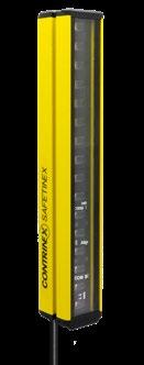

Safety Level Cat. 4, PL e, Type 4, SIL 3 Supply Voltage 24 VDC Polarity PNP Resolution 30 mm (hand) COMMON FEATURES Relay See page 256 Top/bottom mounting bracket For YBB & YCA See page 256 Sliding T-nuts for side mounting See page 256 Mounting bracket No. 5 For YBBS & YBES See page 256 Mounting bracket No. 6 For YBBS & YBES See page 256 Mounting bracket No. 7 For YBBS & YBES See page 256 Safety filter See page 257 Laser alignment tool See page 257 Device columns See page 254 Mirror columns See page 254 Go to page 298 for details ACCESSORIES HAND TYPEPROTECTION4 FAMILYHANDPROTECTION–TYPE4 240 OPERATING RANGE (mm) HOUSING SIZE (mm) SAFETY LIGHT CURTAINS EXTENDED SLIM OUTPUT YBES-30[x]4-[xxxx]-[xxxx] Module [K] Kit (sender + receiver) [R] Receiver [S] Sender Protective height rounded (mm) Connection type [P012] M12 pigtail, 0.3 m, 5 or 8 pins Reference key on page 258 We made these pages with care, but we decline liability for any errors or omissions. 0.25 5 m 26 × 26 (slim) 0.25 5 m 26 × 26 (slim) 0.25 5 m 26 × 26 (slim) 0.25 5 m 26 × 26 (slim) 0.25 5 m 26 × 26 (slim) 0.25 5 m 26 × 26 (slim) 0.25 5 m 26 × 26 (slim) 0.25 5 m 26 × 26 (slim) 0.25 5 m 26 × 26 (slim) 0.25 5 m 26 × 26 (slim) 0.25 5 m 26 × 26 (slim) 0.25 5 m 26 × 26 (slim) 0.25 5 m 26 × 26 (slim) 0.25 5 m 26 × 26 (slim) 0.25 5 m 26 × 26 (slim) 0.25 5 m 26 × 26 (slim) 0.25 … 5 m 26 × 26 (slim) 0.25 … 5 m 26 × 26 (slim) 0.25 … 5 m 26 × 26 (slim) 0.25 … 5 m 26 × 26 (slim) 0.25 … 5 m 26 × 26 (slim) 0.25 … 5 m 26 × 26 (slim) 0.25 … 5 m 26 × 26 (slim) 0.25 … 5 m 26 × 26 (slim) 0.25 … 5 m 26 × 26 (slim) 0.25 … 5 m 26 × 26 (slim) 0.25 … 5 m 26 × 26 (slim) 0.25 … 5 m 26 × 26 (slim)

SAFETY 4TYPEVIEW DATASHEETSSAFETY www.contrinex.com/collections/safety-light-curtains-extended-slim KEY ADVANTAGES 9 Resolution: 30 mm 9 Operating range: 0.25 5 m 9 Protective height: 170 1,610 mm 9 Wireless configuration through Bluetooth® 9 No blind zone 9 Category 4, PL e according to EN/ISO 13849-1 9 Type 4 according to IEC 61496-1 and -2 9 SIL 3 according to IEC 61508 Detailed data sheets for these products can be found on the Contrinex website: 241WWW.CONTRINEX.COM 9 Certified TÜV, CE and UL 9 Enclosure rating IP65 9 Housing profile 26 × 26 mm 9 Beam coding (3 channels), EDM, start and restart interlock configurable functions 9 Optical synchronization 9 Permanent autocontrol PROTECTIVEHEIGHT(mm) HEIGHTTOTAL(mm) WAVELENGTHSENDER(nm) RESPONSETIME(ms) BEAM GAP (mm) OFNUMBERBEAMS TEMPERATUREAMBIENT PROTECTIONDEGREEOF PART REFERENCE 170 170 IR 850 7.8 20 8 0 +55°C IP65 YBES-30K4-0170-P012 330 330 IR 850 9.6 20 16 0 +55°C IP65 YBES-30K4-0330-P012 490 490 IR 850 11.4 20 24 0 +55°C IP65 YBES-30K4-0490-P012 650 650 IR 850 13.2 20 32 0 +55°C IP65 YBES-30K4-0650-P012 810 810 IR 850 15 20 40 0 +55°C IP65 YBES-30K4-0810-P012 970 970 IR 850 16.8 20 48 0 +55°C IP65 YBES-30K4-0970-P012 1,130 1,130 IR 850 18.6 20 56 0 +55°C IP65 YBES-30K4-1130-P012 1,290 1,290 IR 850 20.4 20 64 0 +55°C IP65 YBES-30K4-1290-P012 1,450 1,450 IR 850 22.2 20 72 0 +55°C IP65 YBES-30K4-1450-P012 1,610 1,610 IR 850 24 20 80 0 +55°C IP65 YBES-30K4-1610-P012 170 170 IR 850 7.8 20 8 0 +55°C IP65 YBES-30S4-0170-P012 330 330 IR 850 9.6 20 16 0 +55°C IP65 YBES-30S4-0330-P012 490 490 IR 850 11.4 20 24 0 +55°C IP65 YBES-30S4-0490-P012 650 650 IR 850 13.2 20 32 0 +55°C IP65 YBES-30S4-0650-P012 810 810 IR 850 15 20 40 0 +55°C IP65 YBES-30S4-0810-P012 970 970 IR 850 16.8 20 48 0 +55°C IP65 YBES-30S4-0970-P012 1,130 1,130 IR 850 18.6 20 56 0 +55°C IP65 YBES-30S4-1130-P012 1,290 1,290 IR 850 20.4 20 64 0 +55°C IP65 YBES-30S4-1290-P012 1,450 1,450 IR 850 22.2 20 72 0 +55°C IP65 YBES-30S4-1450-P012 1,610 1,610 IR 850 24 20 80 0 +55°C IP65 YBES-30S4-1610-P012 170 170 IR 850 7.8 20 8 0 +55°C IP65 YBES-30R4-0170-P012 330 330 IR 850 9.6 20 16 0 +55°C IP65 YBES-30R4-0330-P012 490 490 IR 850 11.4 20 24 0 +55°C IP65 YBES-30R4-0490-P012 650 650 IR 850 13.2 20 32 0 +55°C IP65 YBES-30R4-0650-P012 810 810 IR 850 15 20 40 0 +55°C IP65 YBES-30R4-0810-P012 970 970 IR 850 16.8 20 48 0 +55°C IP65 YBES-30R4-0970-P012 1,130 1,130 IR 850 18.6 20 56 0 +55°C IP65 YBES-30R4-1130-P012 1,290 1,290 IR 850 20.4 20 64 0 +55°C IP65 YBES-30R4-1290-P012
Safety Level Cat. 4, PL e, Type 4, SIL 3 Supply Voltage 24 VDC Polarity PNP Resolution 30 mm (hand) COMMON FEATURES Relay See page 256 Top/bottom mounting bracket For YBB & YCA See page 256 Sliding T-nuts for side mounting See page 256 Mounting bracket No. 5 For YBBS & YBES See page 256 Mounting bracket No. 6 For YBBS & YBES See page 256 Mounting bracket No. 7 For YBBS & YBES See page 256 Safety filter See page 257 Laser alignment tool See page 257 Device columns See page 254 Mirror columns See page 254 Go to page 298 for details ACCESSORIES HAND TYPEPROTECTION4 FAMILYHANDPROTECTION–TYPE4 242 OPERATING RANGE (mm) HOUSING SIZE (mm) SAFETY LIGHT CURTAINS EXTENDED SLIM OUTPUT YBES-30[x]4-[xxxx]-[xxxx] Module [K] Kit (sender + receiver) [R] Receiver [S] Sender Protective height rounded (mm) Connection type [P012] M12 pigtail, 0.3 m, 5 or 8 pins Reference key on page 258 We made these pages with care, but we decline liability for any errors or omissions. 0.25 5 m 26 × 26 (slim) 0.25 5 m 26 × 26 (slim)
SAFETY 4TYPEVIEW DATASHEETSSAFETY www.contrinex.com/collections/safety-light-curtains-extended-slim KEY ADVANTAGES 9 Resolution: 30 mm 9 Operating range: 0.25 5 m 9 Protective height: 170 1,610 mm 9 Wireless configuration through Bluetooth® 9 No blind zone 9 Category 4, PL e according to EN/ISO 13849-1 9 Type 4 according to IEC 61496-1 and -2 9 SIL 3 according to IEC 61508 Detailed data sheets for these products can be found on the Contrinex website: 243WWW.CONTRINEX.COM 9 Certified TÜV, CE and UL 9 Enclosure rating IP65 9 Housing profile 26 × 26 mm 9 Beam coding (3 channels), EDM, start and restart interlock configurable functions 9 Optical synchronization 9 Permanent autocontrol PROTECTIVEHEIGHT(mm) HEIGHTTOTAL(mm) WAVELENGTHSENDER(nm) RESPONSETIME(ms) BEAM GAP (mm) OFNUMBERBEAMS TEMPERATUREAMBIENT PROTECTIONDEGREEOF PART REFERENCE 1,450 1,450 IR 850 22.2 20 72 0 +55°C IP65 YBES-30R4-1450-P012 1,610 1,610 IR 850 24 20 80 0 +55°C IP65 YBES-30R4-1610-P012
Safety Level Cat. 4, PL e, Type 4, SIL 3 Supply Voltage 24 VDC Polarity PNP Resolution 14 mm (finger) COMMON FEATURES Relay See page 256 Top/bottom mounting bracket For YBB & YCA See page 256 Sliding T-nuts for side mounting See page 256 Mounting bracket No. 5 For YBBS & YBES See page 256 Mounting bracket No. 6 For YBBS & YBES See page 256 Mounting bracket No. 7 For YBBS & YBES See page 256 Safety filter See page 257 Laser alignment tool See page 257 Device columns See page 254 Mirror columns See page 254 Go to page 298 for details ACCESSORIES FINGER TYPEPROTECTION4 FAMILYFINGERPROTECTION–TYPE4 244 OPERATING RANGE (mm) HOUSING SIZE (mm) SAFETY LIGHT CURTAINS EXTENDED SLIM OUTPUT YBES-14[x]4-[xxxx]-[xxxx] Module [K] Kit (sender + receiver) [R] Receiver [S] Sender Protective height rounded (mm) Connection type [P012] M12 pigtail, 0.3 m, 5 or 8 pins Reference key on page 258 We made these pages with care, but we decline liability for any errors or omissions. 0.4 5 m 26 × 26 (slim) 0.4 5 m 26 × 26 (slim) 0.4 5 m 26 × 26 (slim) 0.4 5 m 26 × 26 (slim) 0.4 5 m 26 × 26 (slim) 0.4 5 m 26 × 26 (slim) 0.4 5 m 26 × 26 (slim) 0.4 5 m 26 × 26 (slim) 0.4 5 m 26 × 26 (slim) 0.4 5 m 26 × 26 (slim) 0.4 5 m 26 × 26 (slim) 0.4 5 m 26 × 26 (slim) 0.4 5 m 26 × 26 (slim) 0.4 5 m 26 × 26 (slim) 0.4 5 m 26 × 26 (slim) 0.4 5 m 26 × 26 (slim) 0.4 … 5 m 26 × 26 (slim) 0.4 … 5 m 26 × 26 (slim) 0.4 … 5 m 26 × 26 (slim) 0.4 … 5 m 26 × 26 (slim) 0.4 … 5 m 26 × 26 (slim) 0.4 … 5 m 26 × 26 (slim) 0.4 … 5 m 26 × 26 (slim) 0.4 … 5 m 26 × 26 (slim)

SAFETY 4TYPE KEY ADVANTAGES 9 Resolution: 14 mm 9 Operating range: 0.4 5 m 9 Protective height: 170 1,290 mm 9 Wireless configuration through Bluetooth® 9 No blind zone 9 Category 4, PL e according to EN/ISO 13849-1 9 Type 4 according to IEC 61496-1 and -2 9 SIL 3 according to IEC 61508 Detailed data sheets for these products can be found on the Contrinex website: 245WWW.CONTRINEX.COM 9 Certified TÜV, CE and UL 9 Enclosure rating IP65 9 Housing profile 26 × 26 mm 9 Beam coding (3 channels), EDM, start and restart interlock configurable functions 9 Optical synchronization 9 Permanent autocontrol PROTECTIVEHEIGHT(mm) HEIGHTTOTAL(mm) WAVELENGTHSENDER(nm) RESPONSETIME(ms) BEAM GAP (mm) OFNUMBERBEAMS TEMPERATUREAMBIENT PROTECTIONDEGREEOF PART REFERENCE VIEW DATASHEETSSAFETY www.contrinex.com/collections/safety-light-curtains-extended-slim 170 170 IR 850 9.6 10 16 0 +55°C IP65 YBES-14K4-0170-P012 330 330 IR 850 13.2 10 32 0 +55°C IP65 YBES-14K4-0330-P012 490 490 IR 850 16.8 10 48 0 +55°C IP65 YBES-14K4-0490-P012 650 650 IR 850 20.4 10 64 0 +55°C IP65 YBES-14K4-0650-P012 810 810 IR 850 24 10 80 0 +55°C IP65 YBES-14K4-0810-P012 970 970 IR 850 27.6 10 96 0 +55°C IP65 YBES-14K4-0970-P012 1,130 1,130 IR 850 31.2 10 112 0 +55°C IP65 YBES-14K4-1130-P012 1,290 1,290 IR 850 34.8 10 128 0 +55°C IP65 YBES-14K4-1290-P012 170 170 IR 850 9.6 10 16 0 +55°C IP65 YBES-14S4-0170-P012 330 330 IR 850 13.2 10 32 0 +55°C IP65 YBES-14S4-0330-P012 490 490 IR 850 16.8 10 48 0 +55°C IP65 YBES-14S4-0490-P012 650 650 IR 850 20.4 10 64 0 +55°C IP65 YBES-14S4-0650-P012 810 810 IR 850 24 10 80 0 +55°C IP65 YBES-14S4-0810-P012 970 970 IR 850 27.6 10 96 0 +55°C IP65 YBES-14S4-0970-P012 1,130 1,130 IR 850 31.2 10 112 0 +55°C IP65 YBES-14S4-1130-P012 1,290 1,290 IR 850 34.8 10 128 0 +55°C IP65 YBES-14S4-1290-P012 170 170 IR 850 9.6 10 16 0 +55°C IP65 YBES-14R4-0170-P012 330 330 IR 850 13.2 10 32 0 +55°C IP65 YBES-14R4-0330-P012 490 490 IR 850 16.8 10 48 0 +55°C IP65 YBES-14R4-0490-P012 650 650 IR 850 20.4 10 64 0 +55°C IP65 YBES-14R4-0650-P012 810 810 IR 850 24 10 80 0 +55°C IP65 YBES-14R4-0810-P012 970 970 IR 850 27.6 10 96 0 +55°C IP65 YBES-14R4-0970-P012 1,130 1,130 IR 850 31.2 10 112 0 +55°C IP65 YBES-14R4-1130-P012 1,290 1,290 IR 850 34.8 10 128 0 +55°C IP65 YBES-14R4-1290-P012
APPLICATION Interlock system with RFID coding protects multiple access points on enclosed conveyor Enclosed conveyors are an efficient way of preventing contamination in hygienic production systems. Doors onto the conveyor are provided wherever the opera tor needs access for set-up, maintenance or trouble shooting. To protect the operator and preserve process hygiene, RFID-coded safety sensors are fitted to each door. These cascadable devices with IP6K9K protection and Ecolab approval, are ideal for hygienic conveyor systems, where they reliably inhibit operation as soon as any door is opened. Automotive production and supply, machine tool, packaging, logistics, materials handling, assembly, automation, robotics Automotive industry Machine tools
systems
INDUSTRIES
LogisticsRobotics


MAGNETIC AND RFID SAFETY SENSORS NON-CONTACT MONITORING OF DOORS Magnetic and RFID safety sensors are ideal for monitoring guard doors, hoods or covers. Their compact housings with standard fixing are particularly suitable for washdown applications in the food industry. RFID types are also ideal for multi-sensor applications, such as long assembly lines. Thanks to non-contact operation and coded communication, service life is very long. ACCESSORIES KEY ADVANTAGES 9 Up to category 4, PL e according to EN/ISO 13849-1 9 Operating distance up to 18 mm 9 PVC cable or M12 pigtail connection 9 Certified TÜV, CE and UL 9 IP6K9K, Ecolab MAGNETIC 9 Safety sensor with frontal or 90° actuation 9 Magnetically coded, ISO 14119 type 4 9 Detection through metal plate possible 9 Sizes 36 × 26 × 13 mm and 88 × 25 × 13 mm RFID 9 Safety sensor with RFID coding (random or teachable) ISO 14119 type 4 9 Compact size 36 × 26 × 13 mm 9 Cascadable up to 30 units 9 EDM and diagnostic function Relay SERIES Housing size mm CUBIC 36 × 26 × 13 RECTANGULAR 88 × 25 × 13 OPERATING )(RANGEmm Magnetic 4 18 8 18 RFID 8 18 PRODUCT OVERVIEW Cables Go to pages 256 and 298 to see all the accessories


Safety Level Cat. 4, PL e, SIL 3 Supply Voltage 24 VDC Temperature Range −25 … +80°C Enclosure Rating IP6K9K COMMON FEATURES Relay See page 256 Top/bottom mounting bracket For YBB & YCA See page 256 Sliding T-nuts for side mounting See page 256 Mounting bracket No. 5 For YBBS & YBES See page 256 Mounting bracket No. 6 For YBBS & YBES See page 256 Mounting bracket No. 7 For YBBS & YBES See page 256 Safety filter See page 257 Laser alignment tool See page 257 Device columns See page 254 Mirror columns See page 254 Go to page 298 for details ACCESSORIES SAFETY MAGNETICSENSORS FAMILYCUBICSTANDARDCUBICEXTENDEDRECTANGULAREXTENDED 248 SAFE SWITCH ON DISTANCE SAO (mm) SAFE SWITCH OFF DISTANCE SAR (mm) SAFETY SENSORS MAGNETIC OUTPUT YSM-[xx][x]4-[xxxx]-[xxxx] Module [K] Kit (sender + receiver) Hole spacing [22] 22 mm [78] 78 mm Connection type [C050] Cable, 5 m, PVC [P012] M12 pigtail, 0.3 m, 4 pins see p. 258 Reference key on page 258 We made these pages with care, but we decline liability for any errors or omissions.4 10 4 10 4 10 4 10 8 17 8 17 8 17 8 17 8 17 8 18 8 18 8 18 8 18 8 18


VIEW DATASHEETSSAFETY www.contrinex.com/collections/magnetic-and-rfid-sensors KEY ADVANTAGES 9 Safety sensor with frontal or 90° actuation 9 Magnetically coded, ISO 14119 type 4 9 Up to category 4, PL e according to EN/ISO 13849-1 9 Operating distance up to 18 mm 9 PVC cable or M12 pigtail connection 9 Sizes 36 × 26 × 13 mm and 88 × 25 × 13 mm 9 Certified TÜV, CE and UL 9 IP6K9K, Ecolab Detailed data sheets for these products can be found on the Contrinex website: 249WWW.CONTRINEX.COM HOUSING SIZE (mm) ACTUATION OFNUMBEROUTPUTS CABLE CONNECTOR PART REFERENCESAFETY MAGNETIC SENSORS 36 × 26 × 13 Frontal 2 × NO 5 m PVC YSM-22K4-MSFN-C050 36 × 26 × 13 Frontal 90° 2 × NO 5 m PVC YSM-22K4-MSAN-C050 36 × 26 × 13 Frontal 2 × NO 0.15 m PVC YSM-22K4-MSFN-P012 36 × 26 × 13 Frontal 90° 2 × NO 0.15 m PVC YSM-22K4-MSAN-P012 36 × 26 × 13 Frontal 2 × NO 5 m PVC YSM-22K4-MEFN-C050 36 × 26 × 13 Frontal 90° 2 × NO 5 m PVC YSM-22K4-MEAN-C050 36 × 26 × 13 Frontal 2 × NO 0.15 m PVC YSM-22K4-MEFN-P012 36 × 26 × 13 Frontal 90° 2 × NO 0.15 m PVC YSM-22K4-MEAN-P012 36 × 26 × 13 Frontal NO, NC 5 m PVC YSM-22K4-MEFL-C050 88 × 25 × 13 Frontal 2 × NO 5 m PVC YSM-78K4-MEFN-C050 88 × 25 × 13 Frontal 90° 2 × NO 5 m PVC YSM-78K4-MEAN-C050 88 × 25 × 13 Frontal 2 × NO 0.15 m PVC YSM-78K4-MEFN-P012 88 × 25 × 13 Frontal 90° 2 × NO 0.15 m PVC YSM-78K4-MEAN-P012 88 × 25 × 13 Frontal NO, NC 5 m PVC YSM-78K4-MEFL-C050

Relay See page 256 Top/bottom mounting bracket For YBB & YCA See page 256 Sliding T-nuts for side mounting See page 256 Mounting bracket No. 5 For YBBS & YBES See page 256 Mounting bracket No. 6 For YBBS & YBES See page 256 Mounting bracket No. 7 For YBBS & YBES See page 256 Safety filter See page 257 Laser alignment tool See page 257 Device columns See page 254 Mirror columns See page 254 Go to page 298 for details ACCESSORIES SAFETY RFIDSENSORS FAMILYCUBICRANDOMCUBICTEACH 250 SAFETY SENSORS RFID SAFE SWITCH ON DISTANCE SAO (mm) SAFE SWITCH OFF DISTANCE SAR (mm) Safety Level Cat. 4, PL e, SIL 3 Supply Voltage 24 VDC Temperature Range −25 … +70°C Enclosure Rating IP6K9K COMMON FEATURES OUTPUT YSR-[xx][x]4-[xxxx]-[xxxx] Module [K] Kit (sender + receiver) Hole spacing [22] 22 mm Connection type [C050] Cable, 5 m, PVC [P012] M12 pigtail, 0.3 m, 8 pins see p. 258 Reference key on page 258 We made these pages with care, but we decline liability for any errors or omissions.8 18 8 18 8 18 8 18


KEY ADVANTAGES 9 Safety sensor with RFID coding (random or teachable) ISO 14119 type 4 9 Category 4, PL e according to EN/ISO 13849-1 9 Operating distance up to 18 mm 9 PVC cable or M12 pigtail connection 9 Compact size 36 × 26 × 13 mm 9 Cascadable up to 30 units Detailed data sheets for these products can be found on the Contrinex website: 251WWW.CONTRINEX.COM SAFETY SENSORSRFID 9 EDM and diagnostic function 9 Certified TÜV, CE and UL 9 IP6K9K, Ecolab HOUSING SIZE (mm) ACTUATION OFNUMBEROUTPUTS CABLE CONNECTOR PART REFERENCE VIEW DATASHEETSSAFETY www.contrinex.com/collections/magnetic-and-rfid-sensors 36 × 26 × 13 RFID random 2 × OSSD 5 m PVC YSR-22K4-RESE-C050 36 × 26 × 13 RFID random 2 × OSSD 0.15 m PVC YSR-22K4-RESE-P012 36 × 26 × 13 RFID teachable 2 × OSSD 5 m PVC YSR-22K4-TESE-C050 36 × 26 × 13 RFID teachable 2 × OSSD 0.15 m PVC YSR-22K4-TESE-P012

Some light curtain applications require special accessories. For example, mirror columns can be used to deflect light beams for multi-sided protection. Also if the distance between the light-curtain sender and receiver is long, a laser tool simplifies alignment. Many other accessories are available in the Accessories section of this catalog (page 298).


PRODUCTMISCELLANEOUSMIRRORACCESSORIESSAFETY&DEVICECOLUMNSOVERVIEW Mirror and ColumnsDevice Relay Mountingbrackets Safety filter Laser alignment tool with:Compatible All light curtains All light curtains and safety sensors Extended Slim light curtains All light curtains All standard basic light curtains MIRROR & DEVICE COLUMNS 9 Multiple or single mirrors available 9 Different heights available RelayMISCELLANEOUS 9 Performance Level (PL) e and category 4 accord ing to EN/ISO 13849-1 9 Manual or automatic restart 9 Short response time Mounting Brackets Top/bottom mounting brackets 9 Synthetic mounting brackets 9 Pair of brackets supplied with each bracket Side/end mounting brackets 9 Metal mounting brackets KEY ADVANTAGES Safety Filter 9 Integrated RC filter for counter signal cut 9 Possibility to connect sender and receiver unit on same connector Laser alignment tool 9 Easily clippable onto Safetinex YBB and YCA devices 9 Range: up to 50 m


Relay See page 256 Top/bottom mounting bracket For YBB & YCA See page 256 Sliding T-nuts for side mounting See page 256 Mounting bracket No. 5 For YBBS & YBES See page 256 Mounting bracket No. 6 For YBBS & YBES See page 256 Mounting bracket No. 7 For YBBS & YBES See page 256 Safety filter See page 257 Laser alignment tool See page 257 Go to page 298 for details ACCESSORIES COLUMNSDEVICEACCESSORIESSAFETYANDMIRROR FAMILYDEVICEANDMIRRORCOLUMNS 254 COLUMN TYPE PART REFERENCE SAFETY ACCESSORIES DEVICE AND MIRROR COLUMNS OUTPUT YXC-[xxxx]-[xxx] Column height in mm Column type [F00] Device (protection) column [M11] Single mirror column [M23] 3 mirror column [M24] 4 mirror column Reference key on page 259 We made these pages with care, but we decline liability for any errors or omissions.Protective YXC-0985-F00 Protective YXC-1285-F00 Protective YXC-1740-F00 Protective YXC-2040-F00 Single mirror YXC-1280-M11 Single mirror YXC-1715-M11 Single mirror YXC-2015-M11 Single mirror YXC-2215-M11 Multiple mirror YXC-1185-M23 Multiple mirror YXC-1285-M24 COLUMNPROTECTIVE


KEY ADVANTAGES 9 Robust protective profile, attractive design 9 Special spring elements automatically reset position in case of mechanical impact 9 Complete assembly kit for both device and floor mounting included 9 Easy to mount: vertical and axial adjustments can be quickly completed in just a few steps Detailed data sheets for these products can be found on the Contrinex website: 255WWW.CONTRINEX.COM LENGTH L1 (mm) LENGTH L2 (mm) LENGTH L3 (mm) LENGTH L4 (mm) LENGTH L5 (mm) SAFETY COLUMNS 9 Single mirror or exchangeable and separately adjustable individual mirrors in accordance with EN 999 VIEW DATASHEETSSAFETY www.contrinex.com/collections/safety-accessories 965 985 1,265 1,285 1,720 1,740 2,020 2,040 1,082 1,281 1,532 1,716 1,682 2,016 1,832 2,216 300 400 400 1,185 300 300 300 300 1,285 SINGLE COLUMNMIRROR MULTIPLE MIRROR COLUMN


256 SAFETY ACCESSORIES MISCELLANEOUS We made these pages with care, but we decline liability for any errors or omissions. TYPE RESPONSETYPICALTIME CONTACTSNUMBEROF MAX.VOLTAGESWITCHING COMPATIBLEWITH PART REFERENCE SIL 3, PL e Cat 4 25 ms (manual start) / 100 ms (automatic start) 3 × NO / 1 × NC 250 V AC/DC Light curtains and sensors YRB-4EML-31S YRB-4EML-31S DESCRIPTION MATERIAL COMPATIBLE WITH PART REFERENCE Top/bottom mounting bracket Plastic YBB and YCA series YXW-0001-000 Sliding T-Nut for side mounting Metal YBB and YCA series YXW-0003-000 Top/bottom mounting brackets Plastic YBES and YBBS series YXW-0005-000 Side/end mounting brackets Metal YBES and YBBS series YXW-0006-000 Side/end mounting brackets Metal YBES and YBBS series YXW-0007-000 MOUNTINGRELAY BRACKETS


Detailed data sheets for these products can be found on the Contrinex website: 257WWW.CONTRINEX.COM SAFETY ACCESSORIESVIEW DATASHEETSSAFETY www.contrinex.com/collections/safety-accessories RANGE LASER BEAM SPOT SIZE LASER CLASS POWER SUPPLY COMPATIBLE WITH PART REFERENCE ≤ 50 m < 10 mm 1 mV (class 2) AA batteries YBB and YCA series YXL-0001-000 LASER ALIGNEMENT TOOL CONNECTORASIDE PINS RC FILTER CONNECTIONBSIDE PART REFERENCE 5 pins 9 YXF-0002-000 T-CONNECTOR SAFETY FILTER


Detailed data sheets for these products can be found on the Contrinex website:258 SAFETY REFERENCE KEY LIGHT CURTAINS AND SAFETY YBB-30S4-0800-G012SENSORS PRODUCT TYPE SAFETY PRODUCT Y ADDITIONNAL INFORMATION Receiver R Sender S Kit (sender + receiver) K Reed sensor R Read/write RFID sensor L Actuator A MODULE Basic standard barrier (light curtain) BB Access control barrier (light curtain) CA Basic slim barrier BBS Extended slim barrier BES Magnetic sensor SM RFID sensor SR Resolution (YBB) 14 mm (finger) 14 30 mm (hand) 30 Operating distance (YCA) 50 m 50 Hole spacing (YSM, YSR) 22 mm 22 78 mm 78 CONNECTION TYPE Category 2 2 Category 4 4 Cable, 5 m, PVC C050 M12 connector, 5 pins G012 M12 Pigtail, 0.3 m, 5 or 8 pins P012 CATEGORYADDITIONNAL INFORMATION Light curtain Protective height rounded in mm #### Coding (safety sensor) Random RFID R### Teachable RFID T### Magnetic T### Distance (safety sensor) Standard #S## Extended #E## Actuation (safety sensor) Frontal ##F# 90° ##A# All sides ##S# Options (safety sensor) No option N Restart button R EDM E with LED L
259WWW.CONTRINEX.COM REFERENCE KEY VIEW DATASHEETSSAFETY www.contrinex.com/collections/safety SAFETY YRB-4EML-241ACCESSORIES PRODUCT TYPE Basic relay RB Light curtain column XC Laser alignment tool XL Mounting brackets XW Filter XF Spacer XS ADDITIONAL INFORMATION SAFETY PRODUCT Y Relay (YRB) Standard functions, 3 NO, 1 NC contacts 4EML Muting functions, 3 NO contacts 0330 Column (YXC) Column height in mm (e.g. 1,060 mm) 1060 Laser alignment tool (YXL) Standard <1 mW (class 2) 0001 Filter (YXF) Standard filter 0001 Spacer (YXS) For YSM-22 series 2200 For YSM-78 series 7800 Mounting brackets (YXW) Top/bottom brackets (YBB/YCA) 0001 Sliding T-nuts (YBB/YCA) 0003 Top/bottom brackets (YBBS/YBES) 0005 Side brackets (YBBS/YBES) 0006 Side/end brackets (YBBS/YBES) 0007 MIRROR / DEVICE COLUMN Device (protection) column F00 Single mirror column M11 3 mirror column M23 4 mirror column M24 STANDARD ACCESSORIES 000 2 channels, type 4, width 22.5 mm 31S 2 channels, type 4, width 45 mm 242 RELAY
Detailed data sheets for these products can be found on the Contrinex website:260

261WWW.CONTRINEX.COM LOW AND RFIDFREQUENCYHIGH RADIO FREQUENCY IDENTIFICATION SYSTEMS (RFID) HIGHLIGHTS 9 Low- and high-frequency (LF and HF) systems networkable on ContriNET or on conventional PC using USB connection 9 Widest fieldbus coverage on market LF SYSTEM 9 All-metal housings, IP68 and IP69K 9 Food safe and saltwater resistant (316L / V4A) 9 All tags embeddable in metal HF SYSTEM 9 ISO/IEC 15693 compatible 9 Fast data transfer time 9 User-defined password protection features NEW 9 HF Read/Write Modules with 9 HF tags for high temperatures 9 LF and HF Read/Write Modules with USB connection

allowing the connection of a maximum of 8 RFID RWMs in parallel on a single IO-Link master, allowing a fast and easy machine setup and reducing programming cost. RFID datas are exchanged over process data reg isters (input/output) at a constant cycle time (typ ically 10 ms) and Contrinex RWMs are compatible with any ISO 15693 transponder on the market. Maximum cable length between an IO-link device and a master is limited by the standard at 20 m. Every RFID system can have one of the following three topologies: 101010101011110011110101011 01001101011111100100011111000110110101001 1001000110111011011011000101101011000111 10100101011110110001111011011011100101011 01010101010100111010101110 0011101010110101110101010110 100101010100011001010110110110111101010100111010101010100110 CONTRINET
Compared to classic systems, such as bar codes or laser marking, RFID technology offers important advan tages. Transponder information can be read or written even when there is no direct line of sight between it and the Read/Write Module. In addition, information can be added, modified or replaced. It is a useful technology for automated production, reducing human error while increasing reliability, flexibility and traceability.
Up to 10 ContriNET RWMs with one USB interface Up to 31 ContriNET RWMs with one industrial bus interface Up to 254 ContriNET RWMs on a half-duplex RS-485 interface
CONTRINET
RFIDINTRODUCTIONSYSTEMS
RFID (Radio Frequency IDentification) is used in numerous automation and logistics domains. It allows objects to be identified by means of electronic labels (transponders or tags).
Detailed data sheets for these products can be found on the Contrinex website:262
ConIdent® (also called ConID) is the general name of the Contrinex RFID system, including transponders, Read/Write Modules and interfaces in both low-frequency (LF) and high-frequency (HF) technology. ContriNET is the product name of the Contrinex RFID network and protocol. The ContriNET protocol uses an RS-485 physical layer, which allows LF and/or HF Read/Write Modules to be daisy-chained, reducing the total number of interfaces.
While the usual interfaces allow connection of a limited number of Read/Write Modules (typically 4), ContriNET RWMs can be used to reduce the number of interfaces, which makes the cost of a ConID system more economic than competitive RFID products.
101010101011110011110101011 01001101011111100100011111000110110101001 1001000110111011011011000101101011000111 10100101011110110001111011011011100101011 In principle, a ContriNET network can extend to a length of 200 ism.a point to point communication standard (ISO 61131-9),


RFIDTRANSPONDERSCOMPONENTS(TAGS)
READ/WRITE MODULES (RWMs) A Read/Write Module is a device that allows data to be read from or written to a transponder.
HIGH-FREQUENCY (HF) RFID (13.56 MHz) Contrinex HF RFID technology complies with ISO/ IEC 15693 and is therefore open to any components that meet this standard. HF systems allow fast communication between transponders and Read/ Write Modules as well as extended functionality for tag dataAnti-collision,ISO/IECprotection.15693 in case of multiple tag High-temperaturedetection tags embeddable in metal (180°C / High-temperature356°F) tags for PWIS/LABS free applications (250°C / 428°F)
An interface connects the Read/Write Modules to an industrial fieldbus. ConID interfaces are available for PROFIBUS, DeviceNet, EtherNet/IP, PROFINET, EtherCAT, POWERLINK, Ethernet TCP/IP and USB.
263INTERFACESWWW.CONTRINEX.COM
Contrinex LF RFID technology features not only conventional plastic components, but also a range of all-metal Read/Write Modules and transponders in stainless steel. These devices are particularly suitable for difficult operating environments where they will be exposed to cleaning, harsh chemicals, water and frost. They are also highly resistant to mechanicalNon-standardshocks. technology (proprietary data Readscommunication)andwrites through metal Works in a metallic environment (fully Highembeddable)resistance in harsh environments
TECHNOLOGYLOW-FREQUENCY(LF)RFID(31.25kHz)
A transponder is an electronic product that stores data. Transponder memory includes a unique pre set number as an identifier and a memory area for writing user application data in relation to tagged product information. Writeable data may include, for example, the object’s history or the parameters of operations to which it will be subjected.
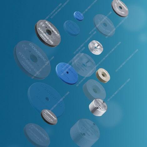


Automotive industry INDUSTRIES Automotive production and supply, machine tool, packaging, logistics, materials handling, assembly, automation, robotics Machine tools
APPLICATION
RFID technology with IO-Link connectivity eliminates hose-coupling errors in fluidized pneumatic-transport systems Bulk-handling- and pneumatic-transport-system designers use RFID technology to eliminate connection errors at manual hose-coupling stations for fluidizable materials. Coupling stations, with IO-Link-enabled RWMs mounted on each outlet pipe, use manual quick-release hoses to feed materials to multiple machines. RFID tags, mounted integrally within each hose coupling and blank ing cap, identify the mating parts uniquely, allowing indi vidual outlet/hose combinations to be verified at the time of connection.
PackagingRobotics systems
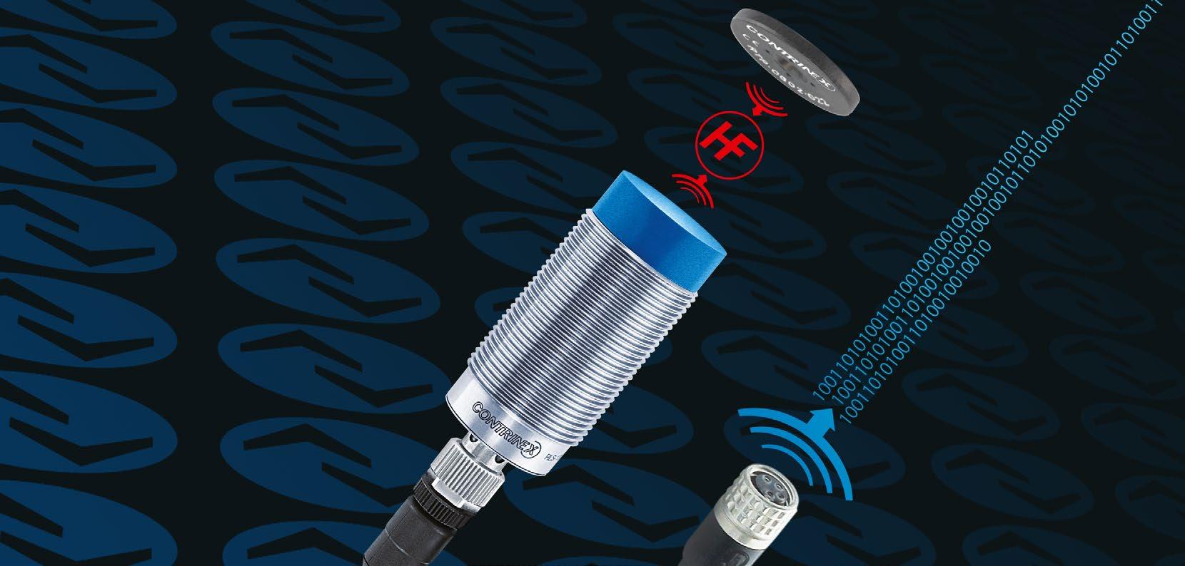

femaleS121 234 RFIDR/W –MODULESEASYTOGO! Ideal for Industry 4.0 solutions, IO-Link read/write modules (RWMs) combine two of the key communication standards in one device: ISO 15693 at the readwrite head for communication with tags and ISO 61131-9 at the S12 connector for communication with the control system. Their simplified, plug-and-play installation ensures easy, cost-effective integration. PRODUCT OVERVIEW Housing size mm M18 M30 C44 Read/write distance max (mm) 26 / 42 58 / 60 80 ACCESSORIES Go to page 290 to see all the accessories KEY ADVANTAGES 9 protocol V1.1 with a single operating mode 9 Device: 9 Scan UID and Read/Write RFID data on transponder whether automatically or trigger based 9 Two alarms configurable to monitor transpon der-in-range time or RSSI level 9 Get UID history list with time stamps 9 Secure mode to add security in the transponder memory access 9 Locate/FindMe function to quickly identify RWM mounted in a machine 9 New Diagnostic function such as individual system time, power-on cycle counter, RFID Error counter 9 Stand-alone SIO: Switching on tag presence, data compar ison and alarm conditions 9 Temperature range −25°C +80°C (−13 176°F) 9 Integral S12 connector with integrated bi-color LED 9 IP67 (IP68 and IP69K for C44) Cables and couplers Handheld devices Starter kits
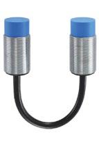


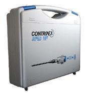


READ/WRITE DISTANCE MAX. (mm) HOUSINGSIZE(mm) FREQUENCYOPERATING STANDARDFAMILY 266 RFID READ/WRITERFID MODULES Starter kits See page 292 Handheld devices See page 292 RFID couplers See page 293 S12 female S12 female Cables See page 288 Go to page 298 for details OUTPUTACCESSORIES RLH-[xxx]PA-NIS Housing size [M18] Cylindrical M18 [M30] Cylindrical M30 [C44] Cubic C44 RLS-1[xx]1-320 Housing size [18] M18 [30] M30 Reference key on pages 294 297 We made these pages with care, but we decline liability for any errors or omissions. 26 M18 ISO/IEC 15693 42 M18 ISO/IEC 15693 58 M30 ISO/IEC 15693 60 M30 ISO/IEC 15693 80 40 × (C44)40 ISO/IEC 15693


USERSIZEMEMORY(BYTE) HOUSING MATERIAL MOUNTING INTERFACE CONNECTION / CONNECTOR TEMPERATUREAMBIENT PART REFERENCE Detailed data sheets for these products can be found on the Contrinex website: 267WWW.CONTRINEX.COM VIEW DATASHEETSRFID www.contrinex.com/collections/rfid-io-link KEY ADVANTAGES 9 protocol V1.1 with a single operating mode 9 Device: • Scan UID and Read/Write RFID data on transponder whether auto matically or trigger based • Two alarms configurable to monitor transponder in range time or RSSI level • Get UID history list with time stamps • Secure mode to add security in the transponder memory access • Locate/FindMe function to quickly identify RWM mounted in a machine • New Diagnostic function such as individ ual system time, power-on cycle counter, RFID Error counter 9 Stand-alone SIO: Switching on tag presence, data comparison and alarm conditions 9 Temperature range −25°C … +80°C (−13 176°F) 9 Integral S12 connector with integrated bi-color LED 9 IP67 (IP68 and IP69K for C44) IO-LINK RWMs 96 Chrome-plated brass Non-embeddable IO-Link × RFID −25 … +80°C RLH-M18PA-NIS 16 Chrome-plated brass Non-embeddable IO-Link × RFID −25 +80°C RLS-1181-320 96 Chrome-plated brass Non-embeddable IO-Link × RFID −25 +80°C RLH-M30PA-NIS 16 Chrome-plated brass Non-embeddable IO-Link × RFID −25 +80°C RLS-1301-320 96 PBTP Non-embeddable IO-Link × RFID −25 … +80°C RLH-C44PA-NIS
APPLICATION
RFID technology for automated testing and tracking of individual motors Product testing lines tipically comprise several test stations, each performing a fixed sequence of tests. For efficient real-time monitoring, identification systems must integrate well into the overall control system. In a typical RFID system, part carriers are equipped with tags and every test station has an RWM. To program the testing machine, the RWM reads from each tag the type of test required for an individual part. After each test, the RWM writes the results back into the appropriate tag memory address/location. Test reports are automatically forwarded to the controller for product acceptance or rejection and fault correction.
INDUSTRIES Automotive production and supply, machine tool, packaging, logistics, materials handling, assembly, automation, robotics industry
Automotive
PackagingRobotics systems Machine tools
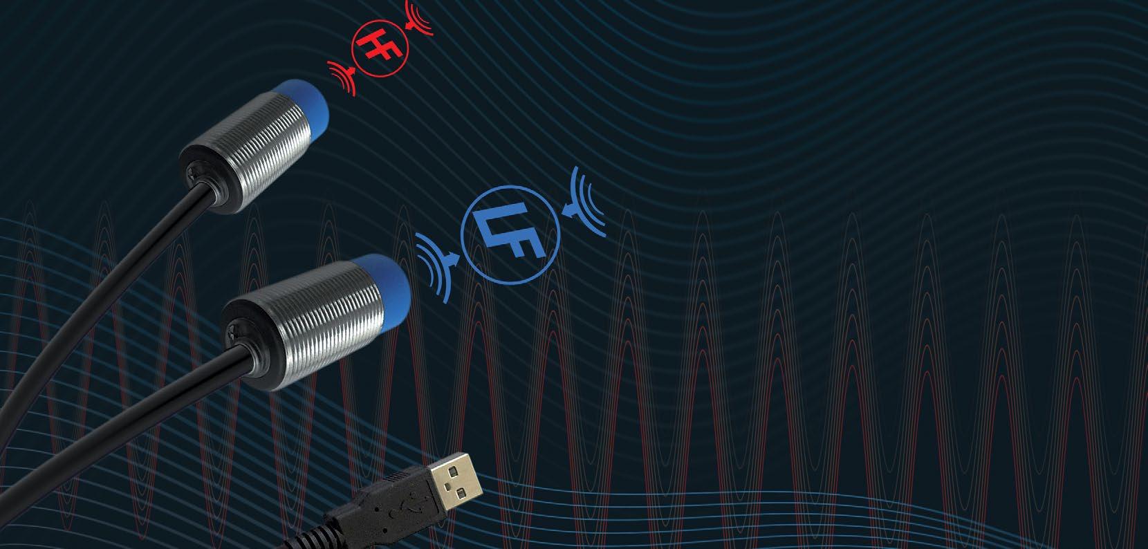

Basic transponders (tags) and read/write modules (RWMs) provide cost-effective solutions with ISO/IEC 15693-compatible HF transponders or proprietary LF transponders. Data protection is excellent, transfer time is fast and all components use the same ContriNET protocol with an RS 485 or USB physical layer. For hardware connection to a PC computer, USB RWMs are an ideal solution as they provide an USB output on their integral connector cable (2 m). PRODUCT ACCESSORIESOVERVIEW Go to page 290 to see all the accessories KEY ADVANTAGES Basic RWMs and tags 9 ContriNET RS-485 protocol with outstanding fieldbus coverage 9 LF and HF RWMs can be daisy-chained on same network 9 HF and LF passive tags, no battery required 9 LF tags embeddable in metal 9 Insensitive to dirt 9 Tag temperature range −40 … +125°C (−40 … +257°F), IP67 9 RWM temperature range −25 +80°C (−13 +176°F), IP67, integral S12 connector USB RWMs and interface 9 ContriNET USB protocol for direct connection to PC (non-networkable) 9 Compatible with ContriNET BASIC support tools and DEMO software 9 DLL for easy development of custom solutions 9 Temperature range −25 +70°C (−13 +158°F), IP67, integral USB A male connector BASICRFID AND USB SYSTEMFIRSTCHOICEFORHIGH AND LOW FREQUENCYHousingsizemm M18 M30 C44 Read/write distance max (mm) 26 / 31 / 36 41 / 58 / 60 80 femaleS121 234 Cables and couplers Handheld devices Starter kits


FAMILYBASICUSB 270 BASICRFID AND USB SYSTEM READ/WRITE MODULES RFID BASIC AND USB SYSTEMREAD/WRITEDISTANCEMAX.(mm) HOUSINGSIZE(mm) FREQUENCYOPERATING STANDARD Starter kits See page 292 Handheld devices See page 292 RFID couplers See page 293 S12 female14 S12 female14 Cables See page 288 Go to page 298 for details OUTPUTACCESSORIES RLH-[xxx]PA-NSS Housing size [M18] Cylindrical M18 [M30] Cylindrical M30 [C44] Cubic C44 RLS-1[xx][x]-0[x]0 Housing size [18] M18 [30] M30 Reference key on pages 294 297 Technology [2] ConIdent HF [3] ConIdent LF Material [1] PBTP / Chrome-plated brass [3] PBTP / Stainless steel V2A We made these pages with care, but we decline liability for any errors or omissions. 26 M18 ISO/IEC 15693 31 M18 ISO/IEC 15693 36 M18 Proprietary 41 M30 Proprietary 58 M30 ISO/IEC 15693 60 M30 ISO/IEC 15693 80 40 × (C44)40 ISO/IEC 15693 31 M18 ISO/IEC 15693 31 M18 ISO/IEC 15693 36 M18 Proprietary 41 M30 Proprietary 60 M30 ISO/IEC 15693 60 M30 ISO/IEC 15693

Detailed data sheets for these products can be found on the Contrinex website: 271WWW.CONTRINEX.COM VIEW RFID DATASHEETS www.contrinex.com/collections/rfid-usbwww.contrinex.com/collections/rfid-basic KEY ADVANTAGES 9 Powerful RS-485 network protocol for LF and HF systems 9 Threaded Read/Write Modules (RWMs) with S12 connector and RS-485 output 9 LF and HF RWMs can be mixed on the same network USERSIZEMEMORY(BYTE) HOUSING MATERIAL MOUNTING INTERFACE CONNECTION / CONNECTOR TEMPERATUREAMBIENT PART REFERENCEBASIC&USBRWMs 400 Chrome-plated brass Non-embeddable ContriNET × RFID −25 … +80°C RLH-M18PA-NSS 400 Stainless steel V2A Non-embeddable ContriNET × RFID −25 +80°C RLS-1183-020 400 Chrome-plated brass Non-embeddable ContriNET × RFID −25 +80°C RLS-1181-030 400 Chrome-plated brass Non-embeddable ContriNET × RFID −25 +80°C RLS-1301-030 400 Chrome-plated brass Non-embeddable ContriNET × RFID −25 … +80°C RLH-M30PA-NSS 400 Stainless steel V2A Non-embeddable ContriNET × RFID −25 +80°C RLS-1303-020 400 PBTP Non-embeddable ContriNET × RFID −25 +80°C RLH-C44PA-NSS 400 Chrome-plated brass Non-embeddable ContriNET USB × RFID −25 +70°C RLS-1181-220 400 Chrome-plated brass Non-embeddable ContriNET USB × RFID −25 +70°C RLS-1181-220-120 400 Chrome-plated brass Non-embeddable ContriNET USB × RFID −25 +70°C RLS-1181-230 400 Chrome-plated brass Non-embeddable ContriNET USB × RFID −25 +70°C RLS-1301-230 400 Chrome-plated brass Non-embeddable ContriNET USB × RFID −25 +70°C RLS-1301-220 400 Chrome-plated brass Non-embeddable ContriNET USB × RFID −25 +70°C RLS-1301-220-120

272 RFID BASIC AND USB SYSTEMRFIDBASIC AND USB SYSTEM TRANSPONDERS FAMILYBASICANDUSB HOUSING SIZE (mm) USERSIZEMEMORY(BYTE) READ/WRITE DISTANCE MAX. (mm) Starter kits See page 292 Handheld devices See page 292 RFID couplers See page 293 Cables See page 288 Go to page 298 for details OUTPUTACCESSORIES RTH-[xxx]QA-N[x]0 Size [D20] ∅ 20 mm [D30] ∅ 30 mm [D50] ∅ 50 mm RLS-1[xx][x]-0[x]0 Size [##] Diameter in mm Reference key on pages 294 297 Communication compatibility [C] ICODE SLI-X [D] FRAM MBR89R118C Material [0] Epoxy [1] PBTP Technology [0] Low Frequency [2] High Frequency ICode SLI-S ISO 15693 We made these pages with care, but we decline liability for any errors or omissions. ∅ 9 160 14 ∅ 16 160 30 ∅ 20 112 34 ∅ 20 160 25 ∅ 20 240 28 ∅ 20 2000 27 ∅ 30 112 44.5 ∅ 30 160 45 ∅ 30 240 29 ∅ 30 2000 45.5 ∅ 50 112 67 ∅ 50 160 60 ∅ 50 240 41 ∅ 50 2000 64.5


Detailed data sheets for these products can be found on the Contrinex website: 273WWW.CONTRINEX.COM KEY ADVANTAGES 9 ContriNET RS-485 protocol with outstanding fieldbus coverage 9 HF and LF passive tags, no battery required 9 LF tags embeddable in metal 9 Insensitive to dirt 9 Tag temperature range −40 … +125°C (−40 … +257°F), IP67 FREQUENCYOPERATING STANDARD MATERIALHOUSING MOUNTING INTERFACE TEMPERATURESTORAGE TEMPERATUREAMBIENT PART REFERENCEBASIC&USBTAGSVIEW RFID DATASHEETS www.contrinex.com/collections/rfid-usbwww.contrinex.com/collections/rfid-basic ISO/IEC 15693 PPS + epoxy Non-embeddable RFID −20 … +110°C −20 … +85°C RTP-0090-020 ISO/IEC 15693 PPS + epoxy Non-embeddable RFID −20 +110°C −20 +85°C RTP-0160-020 ISO/IEC 15693 PPA Non-embeddable RFID −40 +90°C −25 +80°C RTH-D20QA-NC0 ISO/IEC 15693 PBTP Non-embeddable RFID −40 +125°C −25 +85°C RTP-0201-020 Proprietary PBTP Embeddable RFID −40 … +125°C −40 … +125°C RTP-0201-000 ISO/IEC 15693 PPA Non-embeddable RFID −40 +90°C −25 +80°C RTH-D20QA-ND0 ISO/IEC 15693 PPA Non-embeddable RFID −40 +90°C −25 +80°C RTH-D30QA-NC0 ISO/IEC 15693 PBTP Non-embeddable RFID −40 +125°C −25 +85°C RTP-0301-020 Proprietary PBTP Embeddable RFID −40 +125°C −40 +125°C RTP-0301-000 ISO/IEC 15693 PPA Non-embeddable RFID −40 +90°C −25 +80°C RTH-D30QA-ND0 ISO/IEC 15693 PPA Non-embeddable RFID −40 +90°C −25 +80°C RTH-D50QA-NC0 ISO/IEC 15693 PBTP Non-embeddable RFID −40 +125°C −25 +85°C RTP-0501-020 Proprietary PBTP Embeddable RFID −40 +125°C −40 +125°C RTP-0501-000 ISO/IEC 15693 PPA Non-embeddable RFID −40 … +90°C −25 … +80°C RTH-D50QA-ND0

APPLICATION
INDUSTRIES Automotive production and supply, maritime, food and beverage Autoclave application Maritime BreweryAutomotiveindustrypartsensingproductionequipment
RFID technology used to identify workpiece carriers and initiate automated washing In the harsh environment of a washing station, RFID tags and RWMs are exposed to hot water, mechanical shocks, corrosive chemicals and high-pressure jetting. Despite these challenges, identification systems must operate continuously with high reliability. Typically, RFID tags are mounted on the part carriers. On arrival at the washing station, information from the tag is used to select the correct washing cycle for the part type and process.


Read/write modules (RWMs) and embeddable tags from these two ranges feature robust, full-metal, stainless-steel construction. They offer outstanding performance in metallic environments and are insensitive to dirt and metal chips. For the highest mechanical and chemical resistance, Washdown components in food-grade stainless steel (V4A/AISI 316L) are fully sealed and laser welded. They function reliably when immersed in fluids such as water or oil. PRODUCT ACCESSORIESOVERVIEW Go to page 290 to see all the accessories KEY ADVANTAGES 9 LF passive tags, no battery required 9 If the ContriNET protocol is used, LF components can share one network with HF types, including the full range of interfaces 9 Insensitive to dirt 9 Outstanding performance in metallic environments 9 Tags readable/writable through metal 9 Tags fully embeddable, including in metal 9 Enclosure rating IP68 & IP69K Extreme RWMs and tags 9 All-metal, stainless-steel housings (V2A/AISI 304) resist cor rosion, impacts and abrasion 9 Suitable for use in harsh environments, such as the steel industry, agriculture and other outdoor applications 9 Temperature range: tags −40 +95°C (−40 +203°F), RWMs −25 +80°C (−13 +176°F) Washdown RWMs and tags 9 All-metal housings in food-grade stainless steel (V4A/ AISI 316L) resist saltwater, solvents, corrosion, impacts and abrasion 9 Designed for demanding clean-in-place (CIP) applications within the food, pharmaceutical and other industries 9 Temperature range −40 +125°C (−40 +257°F) EXTREMERFID WASHDOWNANDHIGHESTMECHANICALANDCHEMICALRESISTANCEHousingsizemm M18 M30 Read/write distance max (mm) 12 12 femaleS121 234 Cables and couplers Handheld devices Starter kits


276 EXTREMERFID READ/WRITEWASHDOWNANDSYSTEMMODULES RFID EXTREME AND WASHDOWN SYSTEM FAMILYEXTREMEWASH-DOWN READ/WRITE DISTANCE MAX. (mm) HOUSINGSIZE(mm) FREQUENCYOPERATING STANDARD Starter kits See page 292 Handheld devices See page 292 RFID couplers See page 293 3 3Cables See page 288 Go to page 298 for details OUTPUTACCESSORIES RLS-1[xx][x]-03[x] Housing size [18] M18 [30] M30 Reference key on pages 294 297 Temperature [0] Standard up to +80°C [1] High up to +125°C Material [0] Stainless steel V2A [2] Stainless steel V4A We made these pages with care, but we decline liability for any errors or omissions. 12 M18 Proprietary 12 M30 Proprietary 12 M18 Proprietary 12 M30 Proprietary

Detailed data sheets for these products can be found on the Contrinex website: 277WWW.CONTRINEX.COM KEY ADVANTAGES 9 If the ContriNET protocol is used, LF compo nents can share one network with HF types, including the full range of interfaces 9 Insensitive to dirt 9 Outstanding performance in metallic environments 9 Enclosure rating IP68 & IP69K 9 Rugged all-metal LF RWMs with impervious sensing face &EXTREME WASHDOWN RWMs USERSIZEMEMORY(BYTE) HOUSING MATERIAL MOUNTING INTERFACE CONNECTION / CONNECTOR TEMPERATUREAMBIENT PART REFERENCE Extreme 9 Temperature range −25 +80°C (−13 +176°F) Washdown 9 Temperature range −40 +125°C (−40 +257°F) VIEW RFID DATASHEETS www.contrinex.com/collections/rfid-washdownwww.contrinex.com/collections/rfid-extreme 400 Stainless steel V2A Non-embeddable ContriNET × RFID −25 … +80°C RLS-1180-030 400 Stainless steel V2A Non-embeddable ContriNET × RFID −25 +80°C RLS-1300-030 400 Stainless steel V4A Non-embeddable ContriNET × RFID −40 +125°C RLS-1182-031 400 Stainless steel V4A Non-embeddable ContriNET × RFID −40 +125°C RLS-1302-031

278 EXTREMERFID TRANSPONDERSWASHDOWNANDSYSTEM RFID EXTREME AND WASHDOWN SYSTEM FAMILYEXTREMEWASHDOWN HOUSING SIZE (mm) USERSIZEMEMORY(BYTE) READ/WRITE DISTANCE MAX. (mm) Starter kits See page 292 Handheld devices See page 292 RFID couplers See page 293 3 3Cables See page 288 Go to page 298 for details OUTPUTACCESSORIES Temperature [0] Standard up to +80°C [1] High up to +125°C RT[x]-1[xx][x]-00[x] Series [F] All metal [L] All metal, laser welded [M] Metal Reference key on pages 294 297 Type [0] Smooth sleeve [1] Non-embedabble [2] Embedabble Size [##] Diameter in mm We made these pages with care, but we decline liability for any errors or omissions. ∅ 10 240 17 ∅ 16 240 19 M16 240 13 ∅ 26 240 26 M30 240 18 M30 240 23 ∅ 10 240 17 ∅ 16 240 13 M16 240 13 ∅ 26 240 26 M30 240 18 M30 240 18

Detailed data sheets for these products can be found on the Contrinex website: 279WWW.CONTRINEX.COM &EXTREME WASHDOWN TAGS FREQUENCYOPERATING STANDARD MATERIALHOUSING MOUNTING INTERFACE TEMPERATURESTORAGE TEMPERATUREAMBIENT PART REFERENCE KEY ADVANTAGES 9 LF passive tags, no battery required 9 If the ContriNET protocol is used, LF compo nents can share one network with HF types, including the full range of interfaces 9 Insensitive to dirt 9 Outstanding performance in metallic environments 9 Tags readable/writable through metal 9 Tags fully embeddable, including in metal 9 Enclosure rating IP68 & IP69K Extreme 9 Temperature range −40 +95°C (−40 … +203°F) Washdown 9 Temperature range −40 +125°C (−40 +257°F) VIEW RFID DATASHEETS www.contrinex.com/collections/rfid-washdownwww.contrinex.com/collections/rfid-extreme Proprietary Stainless steel V2A Embeddable RFID −40 … +95°C −40 … +80°C RTM-0100-000 Proprietary Stainless steel V2A Embeddable RFID −40 +95°C −40 +80°C RTM-0160-000 Proprietary Stainless steel V2A Embeddable RFID −40 +95°C −40 +80°C RTM-2160-000 Proprietary Stainless steel V2A Embeddable RFID −40 +95°C −40 +80°C RTM-0260-000 Proprietary Stainless steel V2A Embeddable RFID −40 … +95°C −40 … +80°C RTM-2300-000 Proprietary Stainless steel V2A Non-embeddable RFID −40 +95°C −40 +80°C RTF-1300-000 Proprietary Stainless steel V4A Embeddable RFID −40 +125°C −40 +125°C RTL-0102-001 Proprietary Stainless steel V4A Embeddable RFID −40 +125°C −40 +125°C RTL-0162-001 Proprietary Stainless steel V4A Embeddable RFID −40 +125°C −40 +125°C RTL-2162-001 Proprietary Stainless steel V4A Embeddable RFID −40 … +125°C −40 … +125°C RTL-0262-001 Proprietary Stainless steel V4A Embeddable RFID −40 +125°C −40 +125°C RTL-1302-001 Proprietary Stainless steel V4A Embeddable RFID −40 +125°C −40 +125°C RTL-2302-001

INDUSTRIES
APPLICATION
RFID tags withstand elevated temperatures during automotive paint curing Identification components in paint shops are exposed to a variety of rinsing, coating and burning operations, including electrophoresis. Since soiling makes visual identification difficult or impossible, rugged RFID sys tems are an excellent solution. The RFID tag accompa nies each product throughout all painting processes. It can store individual data, including customer require ments, directly on the product or carrier. This allows highly automated customized processes, with smaller batches and central data storage. Automotive production and supply, maritime, food and beverage Paint shop in automotive industry BreweryAutomotiveindustrypartsensingproductionequipment
Maritime


Designed for environments up to 180 or 250°C, High Temperature tags offer exceptional longevity and a thermal-cycling reliability of 1000 hours (or 1000 cycles). Tags are insensitive to dirt and provide between 112 and 2000 Bytes of user memory. As passive devices, no battery or other power source is required. Housings are impervious (IP68 and IP69K). PRODUCT ACCESSORIESOVERVIEW Go to page 290 to see all the accessories KEY ADVANTAGES 9 High frequency, fully compatible with ISO/IEC 15693 9 Exceptionally long life-expectancy, even under intense read/ write and temperature cycling 9 Insensitive to dirt ∅ 26 mm, PPS housing 9 Temperature range −25 … +180°C (−13 … +356°F) 9 Embeddable in metal 9 User memory size (EEPROM): 160 Byte ∅ 50 mm, LCP housing 9 Temperature range −25 +250°C (−13 +482°F) 9 100% silicone-free, ideal for paint-shop applications (LABS free, PWIS-free) 9 User memory size: 9 FRAM technology: 2000 Byte (RTP-0502-062) 9 EEPROM technology: 112 Byte (RTP-0502-082) and 160 Byte (RTP-0502-022) HIGHRFID TEMPERATURE READYTAGSTOBAKEHousingsizemm ∅ 26 mm M30 Read/write distance max (mm) 12 12 femaleS121 234 Cables and couplers Handheld devices Starter kits


282 RFID HIGH TEMPERATURERFIDHIGHTRANSPONDERSTEMPERATURE FAMILYHIGHTEMPERATURE HOUSING SIZE (mm) USERSIZEMEMORY(BYTE) READ/WRITE DISTANCE MAX. (mm) Starter kits See page 292 Handheld devices See page 292 RFID couplers See page 293 S12 female134 S12 female134Cables See page 288 Go to page 298 for details OUTPUTACCESSORIES RTP-0[xx][x]-0[x][x] Reference key on pages 294 297 Technology [2] IC NxP ICODE SLI-S [6] IC FUJITSU FRAM MB89R118C [8] IX NxP ICODE SLI Material [2] LCP [3] PPS Size [26] ∅ 26 mm [50] ∅ 50 mm Temperature [0] Very high up to +150°C [2] Ultra high up to +250°C We made these pages with care, but we decline liability for any errors or omissions. ∅ 26 160 31 ∅ 50 112 42.5 ∅ 50 160 50 ∅ 50 2000 44.5
Detailed data sheets for these products can be found on the Contrinex website: 283WWW.CONTRINEX.COM VIEW DATASHEETSRFID www.contrinex.com/collections/rfid-high-temperature KEY ADVANTAGES 9 High frequency, fully compatible with ISO/IEC 15693 9 Exceptionally long life expectancy, even under intense read/write and temperature cycling 9 Insensitive to dirt 9 PWIS free ∅ 26 mm, PPS housing 9 Temperature range −25 +180°C (−13 +356°F) 9 Embeddable in metal 9 User memory size (EEPROM): 160 Byte HIGH TEMPERATURE TAGS FREQUENCYOPERATING STANDARD MATERIALHOUSING MOUNTING INTERFACE TEMPERATURESTORAGE TEMPERATUREAMBIENT PART REFERENCE ∅ 50 mm, LCP housing 9 Temperature range −25 … +250°C (−13 +482°F) 9 100% silicone-free, ideal for paint-shop applica tions (LABS-free, PWIS-free) 9 User memory size: • FRAM technology: 2000 Byte (RTP-0502-062) • EEPROM technology: 112 Byte (RTP-0502-082) and 160 Byte (RTP-0502-022) ISO/IEC 15693 PPS Embeddable RFID −40 … +180°C −25 … +180°C RTP-0263-020 ISO/IEC 15693 LCP (liquid polymer)crystal Non-embeddable RFID −40 +250°C −25 +150°C RTP-0502-082 ISO/IEC 15693 LCP (liquid polymer)crystal Non-embeddable RFID −40 +250°C −25 +150°C RTP-0502-022 ISO/IEC 15693 LCP (liquid polymer)crystal Non-embeddable RFID −40 +250°C −25 +150°C RTP-0502-062
To bring overall system-integration cost down, an RFID interface is an ideal solution. It simplifies the software integration effort, which typically represents up to 50% of the total implementation cost for a small project. Assuring shortened software-development time at a modest cost premium, Contrinex interfaces are ready to tackle the most demanding and time-critical tasks.


MARKET-LEADINGINTERFACESRFIDFIELDBUS COVERAGE PRODUCT OVERVIEW Interfaces TCP/IPinterfaceindustrial USB Adaptor Cables and connectors 9 Widest fieldbus coverage on market 9 Interfaces for connection of ContriNET to PROFIBUS, DeviceNet, EtherNet/IP, PROFINET, EtherCAT, POWERLINK and Ethernet TCP/IP 9 Comprehensive accessories including T-connectors and line terminators 9 TCP/IP interface in lightweight plastic, 120 × 80 × 30 mm KEY ADVANTAGES INTERFACES 9 Compact, ready-to-use device 9 Allows connection of ContriNET to an industrial fieldbus 9 Synthetic housing in ABS 9 Mounting on rail DIN EN 60715 USB ADAPTOR 9 Synthetic ABS housing 9 Serial RS-485 connection to ContriNET 9 USB connection to control PC


286 RFID INTERFACES We made these pages with care, but we decline liability for any errors or omissions. INDUSTRIAL INTERFACES FOR PLC INDUSTRIALINTERFACEFORPC ADAPTORUSBFORPC FIELDBUS Profibus-DP Devicenet Ethernet/IP / Profinet IO Ethercat / Powerlink Ethernet TCP/IP USB HOUSING SIZE (mm) 100 × 52 × 64 100 × 52 × 64 100 × 52 × 64 155 × 96 × 44 67 × 66 × 28 MATERIALHOUSING ABS ABS ABS Metal ABS MOUNTING DIN rail EN 60715 DIN rail EN 60715 DIN rail EN 60715 DIN rail EN 60715 RANGETEMPERATUREAMBIENT 0 +50°C / +32 +122°F 0 +50°C / +32 +122°F 0 +50°C / +32 +122°F −10 +80°C / −14 +176°F 0 +50°C / +32 +122°F RANGETEMPERATURESTORAGE 0 +50°C / +32 +122°F 0 +50°C / +32 +122°F 0 +50°C / +32 +122°F −20 +85°C / −14 +185°F −40 +85°C / −40 +185°F WEIGHT 150 g 150 g 150 g 635 g 67 g SUPPLYPOWER 18 … 30 V 18 … 30 V 18 … 30 V 10 … 48 V 24 V MAX. CONSUMPTIONCURRENT 130 mA 130 mA 130 mA 160 mA 625 mA (RS-485CONNECTIONSIDE) Connector DB9 Connector DB9 Connector DB9 Terminal block Connector S12 REFERENCEPART RIS-1053-120 RIS-1053-220 RIS-1053-E20 RIS-1208-400 RAS-6766-020


Detailed data sheets for these products can be found on the Contrinex website: 287WWW.CONTRINEX.COM RFID INTERFACESVIEW DATASHEETSRFID www.contrinex.com/collections/rfid CONTRINET APPLICATION WITH INTERFACES M MC APL S YS X3 S12-2MVG-010-NNRN-D9F24VGS12-2FVG-010-NNRN Interfaces V12-5TPD-000-NN1 Industrial24Vfieldbus 200 m maximum Up to 3Read/Write Modules1 AB +24VGND RS-485 A RS-485 B ReadyP1Link 1Port GND+24V S12-2FVG-010-NNRV12-N5TPD-000-NN1 S12-2MVG-010-NNRN RX TX GNABD ETHERNE T S12-2MVGRIS-1208-400MINICONNECTRIS-1208-400


288 RFID INTERFACES We made these pages with care, but we decline liability for any errors or omissions. V12-5TPD-000-NN1S12-2FVG-010-NNRNS12-2MVG-010-NNR2-D9FG 22 S12 maleS12 female S12S12femalemale S12-5MNG-000-NNRN-120WS12-2MVG-010-NNRN ACCESSORIES TO CONNECT INTERFACES TO CONTRINET S12-2MVG-010-NNRN-D9FG DB9 – S12, RS-485 A/B cable – PVC 1 m S12-2FVG-010-NNRN 24V – S12, power supply cable – PVC 1 m S12-2MVG-010-NNRN 2-wire – S12, RS-485 A/B cable – PVC 1 m V12-5TPD-000-NN1 S12 T-connector S12-5MNG-000-NNRN-120W S12 ContriNET terminator 120 Ω DATA
Detailed data sheets for these products can be found on the Contrinex website: 289WWW.CONTRINEX.COM RFID INTERFACESVIEW DATASHEETSRFID www.contrinex.com/collections/rfid ACCESSORIES FOR USB INTERFACE CONNECTION The adaptor acts as the interface between a network of Read/Write Modules and the USB port of the control PC. The delivery package includes a USB cable. EXTERNAL POWER SUPPLY UNIT An external power supply unit (24V / 15W, 625 mA) is included in the delivery package. DRIVERS AND SOFTWARE Drivers compatible with the various Windows versions and software for demonstration and training (ContriNET HF/LF) can be downloaded from the RAS 6766 020 product page of the Contrinex website.

For hard-to-reach applications where it’s impossible to mount a powered RWM close to a tag, passive RFID couplers extend the sensing distance without the need for any physical connection. Optionally, for LF appli cations, a hand-held reader with an integral RWM offers a non-contact alternative.
RFID Starter Kits, available with either LF or HF technology, contain all the elements needed to build a basic RFID system – including RWMs, transponders, cables, connectors and power supply – in a handy carry-case.
Contrinex RFID accessories make it easy for system designers to develop simple applications from scratch.


PRODUCTACCESSORIESRFIDOVERVIEW Starter kits Handheld device RFID couplers STARTER-KIT RFID LF 9 Set containing all the components needed to develop a simple LF RFID application 9 2 read/write modules (RWM) 9 6 transponders 9 1 USB adaptor with power supply 9 Connection cables STARTER-KIT RFID HF 9 Set containing all the components needed to develop a simple HF RFID application 9 2 read/write modules (RWM) 9 5 transponders 9 1 USB adaptor with power supply 9 Connection cables KEY ADVANTAGES HANDHELD DEVICE 9 Portable and light 9 No connector 9 Robust and ergonomic housing 9 Simple navigation 9 Integrated RFID read/write module 9 Belt clip 9 Integrated clock and calendar 9 Dock-in/charging station included RFID COUPLERS 9 Metal threaded cylindrical housings 9 Sensing face of PBTP (polybutylene terephthalate) or stainless steel V2A 9 Insensitive to dirt 9 Passive (without power supply)

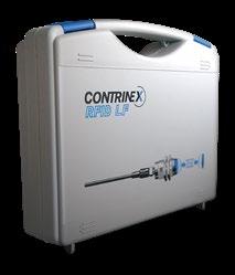


292 RFID ACCESSORIES We made these pages with care, but we decline liability for any errors or omissions. STARTER HANDHELDKITSDEVICEHANDHELDDEVICEHOUSING SIZE (mm) PART REFERENCE 155 × 75 × 49 (with docking station) RPA-0111-000 Handheld read/write device with docking station with EU adapter RPA-0110-000 Handheld read/write device without docking station RPA-0101-000 Docking station with EU adapter RPA-0112-000 Handheld read/write device with docking station with US adapter RPA-0102-000 Docking station with US adapter STARTER KITS HOUSING SIZE (mm) CONTENTS 255 × 205 × 60 1 USB adaptor, 2 RWMs, 6 tags, 2 T-connectors, 1 power supply, 1 USB cable, 2 cablesconnectingRFIDSTARTER-KIT 255 × 205 × 60 1 USB adaptor, 2 RWMs, 5 tags, 2 T-connectors, 1 power supply, 1 USB cable, 2 cablesconnectingRFIDSTARTER-KIT


Detailed data sheets for these products can be found on the Contrinex website: 293WWW.CONTRINEX.COM RFID ACCESSORIESVIEW DATASHEETSRFID www.contrinex.com/collections/rfid RFID COUPLERS DATA dd21L RTx-xxxx-0 0x RCS-1x x0 000 RCS-1x x0 000 RLS-1xxx-030 dd21L RTx- 0xxx-02x RLS-1181-x 20 RCK-1181-x00 RCK-1181-x00 HOUSING SIZE M18 / M30 M18 HOUSING MATERIAL Stainless steel V2A / Chrome-plated brass Chrome-plated brass SENSING MATERIALFACE Stainless steel V2A / PBTP PBTP MOUNTING Non-embeddable Non-embeddable TEMPERATUREAMBIENT RANGE −25 +80°C / −13 +176°F −25 +80°C / −13 +176°F TEMPERATURESTORAGE RANGE −25 +80°C / −13 +176°F −25 +80°C / −13 +176°F CONNECTION TYPE Connector S12 PVC cable, 2 m DEGREE PROTECTIONOF IP68 & IP69K / IP67 IP67 WEIGHT (WITH NUTS) 51 g / 120 g 80 g PART REFERENCE RCS-1301-000RCS-1300-000RCS-1181-000RCS-1180-000 RCK-1181-020


Detailed data sheets for these products can be found on the Contrinex website:294 RFID REFERENCE KEYNEW RFID RLH-C44PA-NISDESIGNATION RFID SYSTEM TYPE L RFID PRODUCTS R ConIdent LF (31.25 kHz) L ConIdent HF (13.56 MHz) H RFID TECHNOLOGY S Smooth sleeve D Threaded cylindrical M High-pressure resistant P Squared C Rectangular R Cylindrical devices M18 18 M30 30 Cubic devices Cubic 4# mm × 4# mm 44 HOUSING SIZE HOUSING TYPE Adapter A Data coupler C Interface I Reader L Portable reader P Transponder T Stainless steel V2A M PBTP P Stainless steel V4A L Epoxy 0 PPA Q PPS R LCP S SENSING FACE MATERIAL CONNECTION / PROGRAMMING EM4056 A ICODE SLI-S B ICODE SLI-X C FRAM MBR89R118C D ICODE SLI E Serial Output S Logic Output L USB connector U IO-Link Output I RS-485 0 PROFIBUS 1 DeviceNet 2 Ethernet/IP 3 TCP/IP 4 PROFINET 5 EtherCAT 6 POWERLINK 8 Blank Programming 0 Pre-programmed 1 Cable connection K Plug connection S Terminal block connection T Rotating ring connection V Embeddable E Non-Embeddable N Standard version (+80°C) A High temperature (+120°C) H Very high temperature (+180°C) V Ultra high temperature (+250°C) U SERIAL EMBEDDABILITYCOMMUNICATIONPERFORMANCECOMPATIBILITY
295WWW.CONTRINEX.COM REFERENCE KEY VIEW DATASHEETSRFID www.contrinex.com/collections/rfid RTM-0160-000TRANSPONDERS TRANSPONDER T RFID PRODUCT R TYPESERIES Diameter [mm] XX SIZE Smooth sleeve 0 Non-embeddable 1 Embeddable 2 All metal F All metal, laser welded L Metal M Plastic P TEMPERATURE Low Frequency 0 High Frequency – ISO 15693 IC NxP ICODE SLI-S 2 High Frequency – ISO 15693 IC Fujitsu FRAM MBR89 6 High Frequency – ISO 15693 IC NxP ICODE SLI 8 Standard up to +80°C 0 High up to +125°C 1 Ultra high up to +250°C 2 Blank 0 Preprogrammed 1MATERIALPROGRAMMINGTECHNOLOGY Epoxy 0 PBTP 1 LCP 2 PPS 3
Detailed data sheets for these products can be found on the Contrinex website:296 RFID REFERENCE KEY RIS-1053-120INTERFACES CONNECTOR S RFID PRODUCTS R Adaptor A Interface ISIZEMODULE Fieldbus / ContriNet 3 RASCONNECTIVITY 66 × 67 mm 6766 RIS 100 × 52 × 64 mm 105 COMMAND SET ContriNet 2 Standard 0 RASPROTOCOLFIELDBUS USB 0 RIS PROFIBUS-DP 1 DeviceNet 2 EtherNet/IP 3 PROFInet IO 5 EtherCAT 6 POWERLINK 8 TCP/IP 400
297WWW.CONTRINEX.COM REFERENCE KEY VIEW DATASHEETSRFID www.contrinex.com/collections/rfid READ/ WRITE RLS-1181-030MODULES TEMPERATURE ConIdent HF 2 ConIdent LF 3 Standard up to +80°C 0 High up to +125°C 1 NETWORKTECHNOLOGYMATERIAL Stainless steel V2A 0 PBTP / Chrome-plated brass 1 Stainless steel V4A 2 PBTP / Stainless steel V2A 3 READ/WRITE MODULE L RFID PRODUCTS R S12 connector, 4-pins S CONNECTION M18 18 M30 30 TYPESIZE Smooth sleeve 0 Non-embedabble 1 Embeddable 2 ContriNet 0 USB 2 IO-Link 3
Detailed data sheets for these products can be found on the Contrinex website:298

299ACCESSORIESWWW.CONTRINEX.COMHIGHLIGHTS 9 Comprehensive cable and connector program 9 IP69K and Ecolab-certified cables for the food and beverage industry (on demand) 9 UL-approved cables and connectors 9 Cables with straight or right-angle sockets 9 Distribution boxes 9 Field-attachable connectors 9 T-connectors (on demand) 9 User-friendly standard portfolio 9 Sensor testers for fast field checks 9 Sensor mounting clamps 9 Bases for mounting clamps 9 Mechanical stops 9 Amplifiers for 3-wire and NAMUR sensors (on demand)

300 ACCESSORIES We made these pages with care, but we decline liability for any errors or omissions. CONNECTOR PINS CONFIG. MATERIALCABLE LENGTHCABLE WIRE CONNECTIONCABLEEND PINS PART REFERENCE 3-pole straight PUR 2 m 3 OPEN CABLE S08-3FUG-020 3-pole straight PUR 5 m 3 OPEN CABLE S08-3FUG-050 3-pole straight PUR 10 m 3 OPEN CABLE S08-3FUG-100 3-pole right angle PUR 2 m 3 OPEN CABLE S08-3FUW-020 3-pole right angle PUR 5 m 3 OPEN CABLE S08-3FUW-050 3-pole right angle PUR 10 m 3 OPEN CABLE S08-3FUW-100 3-pole straight PVC 2 m 3 OPEN CABLE S08-3FVG-020 3-pole straight PVC 5 m 3 OPEN CABLE S08-3FVG-050 3-pole straight PVC 10 m 3 OPEN CABLE S08-3FVG-100 3-pole right angle PVC 2 m 3 OPEN CABLE S08-3FVW-020 3-pole right angle PVC 5 m 3 OPEN CABLE S08-3FVW-050 3-pole right angle PVC 10 m 3 OPEN CABLE S08-3FVW-100 3-pole straight PUR 0.6 m 3 S08-3FUG-006-08MG 3-pole straight PUR 2 m 3 S08-3FUG-020-08MG 3-pole straight PUR 5 m 3 S08-3FUG-050-08MG 3-pole straight PVC 0.6 m 3 S08-3FVG-006-08MG 3-pole straight PVC 2 m 3 S08-3FVG-020-08MG 3-pole straight PVC 5 m 3 S08-3FVG-050-08MG INDUCTIVE & PHOTOELECTRIC CABLES Group A M8 3-PIN open ended wire connecting cables


Detailed data sheets for these products can be found on the Contrinex website: 301WWW.CONTRINEX.COM VIEW DATASHEETSCONNECTIVITY www.contrinex.com/collections/connectivity CONNECTIVITY CONNECTOR PINS CONFIG. OUTER ∅ WIRE ∅ PART REFERENCE CONNECTOR PINS NUMBER CONNECTIONSOF CONNECTIONTYPE PART REFERENCE 3-pole straight 3.0–5.0 0.08–0.38 S08-3FNG-000-NNT1 3-pole straight 4.0–8.0 0.14–0.50 S08-3FNG-000-NNT2 3-pole straight 3.0–5.0 0.08–0.38 S08-3MNG-000-NNT1 3-pole straight 4.0–8.0 0.14–0.50 S08-3MNG-000-NNT2 3-pole Universal – Hood No cable V08-30PE-000-NNN 3-pole 10 Plug boxDistribution PUR cable 5 m V08-31PD-050-UYN 3-pole 10 Outputs – Hood PUR cable 5 m V08-31PH-050-UNN 3-pole 4 DistributionPlug box No cable (hood needed) V08-34PB-000-NYN 3-pole 4 DistributionPlug box PUR cable 5 m V08-34PD-050-UYN 3-pole 8 DistributionPlug box No cable (hood needed) V08-38PB-000-NYN 3-pole 8 DistributionPlug box PUR cable 5 m V08-38PD-050-UYN 3-pole 8 Outputs – Hood PUR cable 5 m V08-38PH-050-UNN FIELD ATTACHABLE CONNECTORS DISTRIBUTION BOXES


302 ACCESSORIES We made these pages with care, but we decline liability for any errors or omissions. CONNECTOR PINS CONFIG. MATERIALCABLE LENGTHCABLE WIRE CONNECTIONCABLEEND PINS PART REFERENCE 4-pole straight PUR 2 m 4 OPEN CABLE S08-4FUG-020 4-pole straight PUR 5 m 4 OPEN CABLE S08-4FUG-050 4-pole straight PUR 10 m 4 OPEN CABLE S08-4FUG-100 4-pole right angle PUR 2 m 4 OPEN CABLE S08-4FUW-020 4-pole right angle PUR 5 m 4 OPEN CABLE S08-4FUW-050 4-pole right angle PUR 10 m 4 OPEN CABLE S08-4FUW-100 4-pole straight PVC 2 m 4 OPEN CABLE S08-4FVG-020 4-pole straight PVC 5 m 4 OPEN CABLE S08-4FVG-050 4-pole straight PVC 10 m 4 OPEN CABLE S08-4FVG-100 4-pole right angle PVC 2 m 4 OPEN CABLE S08-4FVW-020 4-pole right angle PVC 5 m 4 OPEN CABLE S08-4FVW-050 4-pole right angle PVC 10 m 4 OPEN CABLE S08-4FVW-100 4-pole straight PUR 2 m 4 S08-4FUG-020-12MG 4-pole right angle PUR 2 m 4 S08-4FUW-020-08MG 4-pole straight PVC 2 m 4 S08-4FVG-020-12MG 4-pole right angle PVC 2 m 4 S08-4FVW-020-08MG INDUCTIVE & PHOTOELECTRIC CABLES Group B M8 4-PIN open ended wire connecting cables
Detailed data sheets for these products can be found on the Contrinex website: 303WWW.CONTRINEX.COM VIEW DATASHEETSCONNECTIVITY www.contrinex.com/collections/connectivity CONNECTIVITY CONNECTOR PINS CONFIG. MATERIALCABLE LENGTHCABLE WIRE CONNECTIONCABLEEND PINS PART REFERENCE 4-pole straight PUR 2 m 4 OPEN CABLE S12-4FUG-020 4-pole straight PUR 5 m 4 OPEN CABLE S12-4FUG-050 4-pole straight PUR 10 m 4 OPEN CABLE S12-4FUG-100 4-pole straight PUR 15 m 4 OPEN CABLE S12-4FUG-150 4-pole straight PUR 20 m 4 OPEN CABLE S12-4FUG-200 4-pole straight PUR 25 m 4 OPEN CABLE S12-4FUG-250 4-pole right angle PUR 2 m 4 OPEN CABLE S12-4FUW-020 4-pole right angle PUR 5 m 4 OPEN CABLE S12-4FUW-050 4-pole right angle PUR 10 m 4 OPEN CABLE S12-4FUW-100 4-pole right angle PUR 15 m 4 OPEN CABLE S12-4FUW-150 4-pole right angle PUR 20 m 4 OPEN CABLE S12-4FUW-200 4-pole right angle PUR 25 m 4 OPEN CABLE S12-4FUW-250 4-pole straight PVC 2 m 4 OPEN CABLE S12-4FVG-020 4-pole straight PVC 5 m 4 OPEN CABLE S12-4FVG-050 4-pole straight PVC 10 m 4 OPEN CABLE S12-4FVG-100 4-pole right angle PVC 2 m 4 OPEN CABLE S12-4FVW-020 4-pole right angle PVC 5 m 4 OPEN CABLE S12-4FVW-050 4-pole right angle PVC 10 m 4 OPEN CABLE S12-4FVW-100 4-pole straight PUR 0.6 m 4 S12-4FUG-006-12MG 4-pole straight PUR 2 m 4 S12-4FUG-020-12MG 4-pole straight PUR 5 m 4 S12-4FUG-050-12MG 4-pole straight PVC 0.6 m 4 S12-4FVG-006-12MG 4-pole straight PVC 2 m 4 S12-4FVG-020-12MG 4-pole straight PVC 5 m 4 S12-4FVG-050-12MG INDUCTIVE & PHOTOELECTRIC CABLES Group C M12 4-PIN open ended wire connecting cables
304 ACCESSORIES We made these pages with care, but we decline liability for any errors or omissions. CONNECTOR PINS CONFIG. OUTER ∅ WIRE ∅ PART REFERENCE 3-pole straight 3.0–5.0 0.08–0.38 S12-3FNG-000-NNT1 3-pole straight 3.0–5.0 0.08–0.38 S12-3MNG-000-NNT1 4-pole straight 3.0–5.0 0.08–0.38 S12-4FNG-000-NNT1 4-pole straight 4.0–8.0 0.14–0.50 S12-4FNG-000-NNT2 4-pole straight 5.5–8.0 0.50–1.00 S12-4FNG-000-NNT3 4-pole right angle 3.0–5.0 0.08–0.38 S12-4FNW-000-NNT1 4-pole straight 3.0–5.0 0.08–0.38 S12-4MNG-000-NNT1 4-pole straight 4.0–8.0 0.14–0.50 S12-4MNG-000-NNT2 4-pole straight 5.5–8.0 0.50–1.00 S12-4MNG-000-NNT3 4-pole right angle 3.0–5.0 0.08–0.38 S12-4MNW-000-NNT1 FIELD ATTACHABLE INDUCTIVECONNECTORS&PHOTOELECTRIC CABLES Group C
Detailed data sheets for these products can be found on the Contrinex website: 305WWW.CONTRINEX.COM VIEW DATASHEETSCONNECTIVITY www.contrinex.com/collections/connectivity CONNECTIVITY CONNECTOR PINS NUMBER CONNECTIONSOF CONNECTIONTYPE PART REFERENCE 5-pole Universal – Hood No cable V12-50PE-000-NNN 5-pole 4 DistributionPlug box Connector M23 V12-54MG-023-NYN 5-pole 4 DistributionPlug box No cable (hood needed) V12-54PB-000-NYN 5-pole 4 DistributionPlug box PUR cable 2 m V12-54PD-020-UYN 5-pole 4 DistributionPlug box PUR cable 5 m V12-54PD-050-UYN 5-pole 4 DistributionPlug box PUR cable 10 m V12-54PD-100-UYN 5-pole 4 Plug Distribution box + Hood PUR cable 5 m V12-54PY-050-UYN 5-pole 8 Plug DistributionMetalbox PUR cable 5 m V12-58MD-050-UYN 5-pole 8 Plug DistributionMetalbox PUR cable 10 m V12-58MD-100-UYN 5-pole 8 Plug DistributionMetalbox Connector M23 V12-58MG-023-NYN 5-pole 8 DistributionPlug box No cable (hood needed) V12-58PB-000-NYN 5-pole 8 DistributionPlug box PUR cable 2 m V12-58PD-020-UYN 5-pole 8 DistributionPlug box PUR cable 5 m V12-58PD-050-UYN 5-pole 8 DistributionPlug box PUR cable 10 m V12-58PD-100-UYN 5-pole 8 Plug Distribution box + Hood PUR cable 2 m V12-58PY-020-UYN 5-pole 8 Plug Distribution box + Hood PUR cable 5 m V12-58PY-050-UYN DISTRIBUTION BOXES
306 ACCESSORIES We made these pages with care, but we decline liability for any errors or omissions. CONNECTOR PINS CONFIG. MATERIALCABLE LENGTHCABLE WIRE CONNECTIONCABLEEND PINS PART REFERENCE 3 straight PUR 2 m 3 OPEN CABLE S13-3FUG-020 3 straight PUR 5 m 3 OPEN CABLE S13-3FUG-050 3 right angle PUR 2 m 3 OPEN CABLE S13-3FUW-020 3 right angle PUR 5 m 3 OPEN CABLE S13-3FUW-050 INDUCTIVE & PHOTOELECTRIC CABLES Group D M12 AC/DC 3-PIN

Detailed data sheets for these products can be found on the Contrinex website: 307WWW.CONTRINEX.COM VIEW DATASHEETSACCESSORIES www.contrinex.com/collections/accessories ACCESSORIES HOUSING COMPATIBILITYSIZE TYPE PART REFERENCE INNER ∅ OUTER ∅ PLUNGERTYPE MAX.HOUSINGONFORCE MAX. FORCE ON PLUNGER PART REFERENCE ∅ 3 without limit stop ASU-0001-030 ∅ 4 without limit stop ASU-0001-040 ∅ 5 without limit stop ASU-0001-050 ∅ 6.5 without limit stop ASU-0001-065 ∅ 8 without limit stop ASU-0001-080 ∅ 8 with limit stop ASU-0002-080 ∅ 12 mm without limit stop ASU-0001-120 ∅ 12 mm with limit stop ASU-0002-120 ∅ 18 mm without limit stop ASU-0001-180 ∅ 18 mm with limit stop ASU-0002-180 M5 × 0.5 M8 × 1 Flat1 8,000 N 2,000 N AMS-0001-M08 M5 × 0.5 M8 × 1 Spherical2 8,000 N 2,000 N AMS-0002-M08 M8 × 1 M12 × 1 Flat1 15,000 N 2,000 N AMS-0001-M12 M8 × 1 M12 × 1 Spherical2 15,000 N 2,000 N AMS-0002-M12 UNIVERSAL MOUNTING BRACKETS Group E UNIVERSAL MOUNTING BRACKETS MECHANICAL STOPS 1 2 Material: Steel XC 48, black Max. tightening torque: 30 Nm (M8), 50 Nm (M12)


308 ACCESSORIES We made these pages with care, but we decline liability for any errors or omissions. HOUSING COMPATIBILITYSIZE BRACKET MATERIAL PART REFERENCE C23PA series Stainless steel V2A LXW-C23PA-000 C23PA series Stainless steel V2A LXW-C23PA-001 C23PA series Stainless steel V2A LXW-C23PA-002 C23PA series Stainless steel V2A LXW-C23PA-003 DGI series MGI series Stainless steel V2A LXW-DGMGA-000 PHOTOELECTRIC MOUNTING BRACKETS Group F


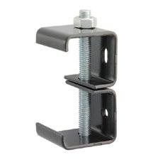
Detailed data sheets for these products can be found on the Contrinex website: 309WWW.CONTRINEX.COM VIEW DATASHEETSACCESSORIES www.contrinex.com/collections/accessories ACCESSORIES HOUSING COMPATIBILITYSIZE BRACKET MATERIAL PART REFERENCE M18PA series ABS/PMMA LHW-M18PA-000 M18PA series ABS/PMMA LLW-M18PA-000 M18PA series ABS/PMMA LTW-M18PA-000 M18PA series ABS LXW-M18PA-000 M18PA series Polyamide LXW-M18PA-001


310 ACCESSORIES We made these pages with care, but we decline liability for any errors or omissions. DIMENSIONS PART REFERENCE ∅ 26 mm LXR-0000-025 ∅ 46 mm LXR-0000-046 ∅ 82 mm LXR-0000-084 32 × 20 mm LXR-0001-032 60 × 20 mm LXR-0001-062 ∅ 26 mm LXU-0000-025 ∅ 82 mm LXU-0000-084 32 × 20 mm LXU-0001-032 60 × 41 mm LXU-0001-064 PHOTOELECTRIC REFLECTORS Group G REFLECTORS


Detailed data sheets for these products can be found on the Contrinex website: 311WWW.CONTRINEX.COM VIEW DATASHEETSACCESSORIES www.contrinex.com/collections/accessories ACCESSORIES SENSOR TESTER Group H PART REFERENCE ATE-0000-010

312 We made these pages with care, but we decline liability for any errors or omissions. ACCESSORIES REFERENCE KEY CABLES / S12-4FAG-020[-NNLN-12MG]CONNECTORS CONNECTION CABLE S 3-pole 3 4-pole 4 5-pole 5 8-pole 8 11-pole B 19-pole J NUMBER OF POLES Female (socket) F Male (plug) M No cable N PVC V PUR U TPE-S A CABLE CONNECTORMATERIALTYPE M8 08 M12 12 M12 AC/DC 13 M23 23 Straight G Right-angle W CABLE EXIT (FEMALE) Male (plug) M Female (socket) F Straight G Right-angle W Standard N Quick-lock Q Cable ∅ 3.0–5.0 mm / wire 0.08–0.38 mm2 1 Cable ∅ 4.0–8.0 mm / wire 0.14–0.50 mm2 2 Cable ∅ 5.5–8.0 mm / wire 0.5–1.0 mm2 3 Standard N Food L RFID R Field attachable T Safety S No cable 000 0.3 m 003 0.6 m 006 1 m 010 1.5 m 015 2 m (standard) 020 5 m 050 10 m 100 15 m 150 20 m 200 25 m 250 CABLE LENGTH M8 08 M12 12 M23 23 Standard or no cable N Shielded W Yes, PNP Y Yes, NPN Z No N LEDCABLE EXIT (MALE) CONNECTOR SIZE FEMALE EXECUTIONAPPLICATIONCONNECTION TYPE CONNECTOR SIZE MALE CONNECTOR TYPE
Detailed data sheets for these products can be found on the Contrinex website: 313WWW.CONTRINEX.COM REFERENCE KEY VIEW DATASHEETSCONNECTIVITY www.contrinex.com/collections/connectivity DISTRIBUTION BOXES AND V12-58PD-050-UYNT-CONNECTORS(-###) DISTRIBUTION BOX V OR POLECONNECTIONST-CONNECTORNUMBEROF CONNECTIONS Hood for all types 0 2 connections T 4 connections 4 6 connections 6 8 connections 8 10 connections 1 NUMBER OF CONNECTIONS 3-pole 3 4-pole 4 5-pole 5 8-pole 8 Accessory 00 M8 08 M12 12 SPECIAL EXECUTIONS Standard (passive distribution box) N Wiring according diagram no. # Yes Y No NCABLELEDTECHNOLOGYMATERIAL No cable N PVC V PUR U Plastic P Metal M MATERIAL Distribution box with cable / T-connector D Distribution box for straight connection G Distribution box for right-angle connection W Base element without hood B Hood with cable H Hood without cable E Base element + hood with cable Y TYPE CONNECTION No cable 000 Cable 0.3 m 003 Cable 2 m 020 Cable 5 m 050 Cable 10 m 100 Connector M12 012 Connector M23 023
314 We made these pages with care, but we decline liability for any errors or omissions. ACCESSORIES REFERENCEAPT-0001-010KEY ACCESSORY A Mechanical stop MS Protective tube PT Tester TE Mechanical stops Outer diameter M08=M8 × 1 thread M08 Outer diameter M12=M12 × 1 thread M12 Mechanical stops Flat plunger 1 Spheric plunger 2 SERIES ACCESSORY TYPE ProtectiveDIMENSIONStubes Inner ∅ 3.5 mm / Outer ∅ 6.0 mm 0 Inner ∅ 6.5 mm / Outer ∅ 10.0 mm 1 Inner ∅ 13.0 mm / Outer ∅ 17.5 mm 2 Inner ∅ 19.0 mm / Outer ∅ 23.5 mm 3 Protective tubes, Tester Material PTFE, spiral, split 000 MATERIAL Protective tubes Length in dm (1 m) 010 Length in dm (10 m) 100LXW-C23PA-000MISCELLANEOUS PHOTOELECTRIC SENSOR L Mounting bracket W Incremental number 000 Incremental number 001 Incremental number 002 Incremental number 003 Standard A, B PERFORMANCE DEVICE TYPE INCREMENTAL NUMBER C23PA series C23PA DGI, MGI series DGM M18PA series M18PA HOUSING SIZE COMPATIBILITY With background suppression H Through-beam sensor L Diffuse sensor T Accessories X SENSOR TYPE Stainless steel V4A G Plastic P PHOTOELECTRIC MOUNTING BRACKETS AND SPECIALTesterHOUSINGMOUNTINGSMATERIAL Base 0
Detailed data sheets for these products can be found on the Contrinex website: 315WWW.CONTRINEX.COM REFERENCE KEY VIEW DATASHEETSACCESSORIES www.contrinex.com/collections/accessories ASU-0001-030 Mounting brackets SU ∅ 3 mm 030 ∅ 4 mm 040 ∅ 5 mm 050 ∅ 6.5 mm 065 ∅ 8 mm 080 ∅ 12 mm 120 ∅ 18 mm 180 ∅ 30 mm 300 Without limit stop 1 With limit stop 2 For C44 3 For 4#5# 4 For C1717 5 DIMENSIONS Standard Basic fixture 00 Standard Cylindrical fixture 30 MOUNTING BRACKETS Plastic 0 Stainless steel V2A 1 Coated steel 4 ACCESSORY A ACCESSORY TYPE FIXTURE PHOTOELECTRICLXR-0000-025REFLECTORS PHOTOELECTRIC SENSOR L Cylindrical reflector 0000 Rectangular reflector 0001 Cylindrical reflectors ∅ 26 mm 025 ∅ 46 mm 046 ∅ 82 mm 084 SHAPE DIMENSIONS Reflector R Reflector for UV U DEVICE TYPE Accessories X SENSOR TYPE Rectangular reflectors 32 × 20 mm 032 60 × 20 mm 062 60 × 41 mm 064 TYPEMATERIAL
Detailed data sheets for these products can be found on the Contrinex website:316

317GLOSSARYWWW.CONTRINEX.COM 9 Autocollimation 9 Background suppression 9 Classics family 9 Excess-gain indication (system reserve indication) 9 Extra distance family 9 Full Inox family 9 Hysteresis 9 IO-Link 9 Mounting 9 Operating distance 9 Parallel connection 9 Sensing range 9 Series connection 9 Smart Sensors 9 Standards 9 Switching frequency 9 Tightening torque 9 Wiring

EXTRA FAMILYDISTANCE
The Classics family (series 600) is one of three inductive sensing technologies offered by Con trinex. Classics family sensors rely on conven tional inductive oscillator and coil technology (see page Sensors30).are sized from ∅ 3 up to M30 and C44 (40 × 40 mm). PNP, NPN and 2 wire AC/DC out put configurations are available, combined with sensing distances between 0.6 mm and 40 mm. The Classics technology family includes devices from the following ranges: Basic, Miniature, 2 Wire, Extra Pressure, Extra Temperature, High Temperature and Washdown
. INDUCTIVE SENSORS PHOTOELECTRIC SENSORS
E
The Extra Distance family (series 500/520) is one of three inductive sensing technologies offered by Contrinex. Extra Distance family sensors rely on conventional inductive oscillator and coil technol ogy, but with a completely different signal evalu ation circuit for better stability and therefore long operating distances. The most important contri bution to this comes from the Contrinex Condist® oscillator (see page 30). Sensors are sized from ∅ 4 to M30, with long oper ating distances up to 40 mm. The Extra Distance technology family includes devices from the Basic, Miniature, Extra Pres sure, High Pressure and Analog Output ranges.
B A Depending on the distance of the target from the device, the light falls on a particular spot of the PSD, and a corresponding reception signal is emitted, indicating that an object is present at a certain dis tance from the device. The analyzing circuit com pares the signal received with the preset operating distance (adjusted by means of the built-in poten tiometer), and, if the distance of the object is less than, or equal to, the preset operating distance, the output is switched. Contrary to an energetic diffuse sensor, the operating distance depends only to a very small extent on the target’s size or color, or on the nature of its surface. The object can therefore be easily discerned, even against a light background.
receivingandopticssemi-transparentmirrorreceiveremitter
emitting
The excess-gain indication circuit detects the excess radiation power which falls on the light incidence surface and is processed by the light receiver. The excess gain can decrease in time due to dirt, a change in the target’s reflection factor, and aging of the emitter diode, so that reliable opera tion can no longer be guaranteed. Some devices are therefore equipped with a second LED (green), which lights up when less than approximately 80% of the available operating distance is used. Models with an excess-gain output make the excess-gain signal available to the user for further processing. Thus, operating conditions which are no longer reliable can be recognized in time. hysteresis excess gain
Fig. 12 reflector
axisoptical
C CLASSICS FAMILY
B SUPPRESSIONBACKGROUND
Detailed data sheets for these products can be found on the Contrinex website:318 AGLOSSARYAUTOCOLLIMATION
Photoelectric sensors using the autocollimation principle are characterized by the fact that the opti cal axes of the emitting and receiving channels are identical. This is possible with light from one of the channels being deflected by means of a semi trans parent mirror (Fig. 12). This principle completely eliminates the interfering blind zone often found in the proximity of the sensor, which is of special advantage when using reflex sensors.
The light pulse from the emitting diode leaves the optical system as a focused, almost parallel, light beam. On meeting an object in its path, part of the beam is diffusely reflected, and in turn, part of this reflected light falls on the PSD (Position-Sensitive Device) housed in the same sensor (Fig. 13). Fig. 13 target pos. A pos. B opticsreceiving opticsemitting (receiver)PSD emitter
INDICATION)(SYSTEMINDICATIONEXCESS-GAINRESERVE
outputswitchingLED)outputexcess-gainstrengthsignal(green(yellow LED) Fig. 14
H HYSTERESIS Hysteresis (differential travel) causes a defined switching behavior of the device (Fig. 15). The sensing range always refers to the switch-on point. Distance hysteresis is only useful for the diffuse sensor model and its related fiber version. switch-on point switch-offhysteresispoint (yellowoutputswitchingstrengthsignalLED) Fig. 15 Hysteresis (differential travel) causes a defined switching behavior of the device (Fig. 16). The operating distance always refers to the switch-on point. Namur devices and those with analog output have continuous transmission behavior, i.e. there is no hysteresis. direction of movement switch-off point switch-on point hysteresis operating distance s curvesresponse Fig. 16 I IO-LINK IO-Link is an industry-standard (IEC 61131-9) point-to-point communication protocol for digital sensors and actuators. Using simple three- or fourwire cables, IO-Link enables these devices to com municate via an IO-Link master to any industrial fieldbus network, or directly using a standard IO signal. IO-Link is highly flexible, allowing user defined sensor configuration of many functions.
F FULL FAMILYINOX
MMOUNTINGEMBEDDABLESENSORS
Embeddable sensors may be flush mounted in all metals. For trouble-free operation, a free zone according to Fig. 17 should be observed.
The Full Inox family (series 700) is one of three inductive sensing technologies offered by Con trinex. Full Inox family sensors rely on Contrinex’s Condet® technology (see page 31). Full Inox sensors have a one-piece, stainless steel housing and are exceptionally robust and chemi cally resistant. They are not only the most durable inductive sensors on the market, but also offer long operating distances on any conductive metal. Sensors are sized from ∅ 4 to M30 and cuboid variant of 20 × 32 × 8 mm, with long operating distances up to 40 mm and protection class IP67 and IP69K. The Full Inox technology family includes devices from the Basic, Miniature, Extreme, High Pres sure, Washdown, Weld-Immune, Chip-Immune, Double-Sheet and Maritime ranges.
zonemetal-freesensingface
3>×snX D
Fig. 18 NON-EMBEDDABLE SENSORS When mounting non-embeddable sensors in con ducting materials (metals), minimum distances to the conducting material must be maintained according to Fig. 19. Flush mounting in non-con ducting materials is permitted.
Fig. 19 D Y* YY
D + 2 × sn
D + 2 × sn zonemetal-freesensingface
3>×sn D Fig. 17 QUASI-EMBEDDABLE SENSORS When installing quasi-embeddable Extra Distance sensors (500 and 520 series) in conductive mate rials (metals), the devices must protrude by a dis tance X, according to Fig. 18. Further, a free zone of 3 × sn must be observed. Flush mounting in non-conducting materials is permitted.
319WWW.CONTRINEX.COM
P CONNECTIONPARALLEL
Connecting sensors in parallel, in order to perform logic functions, is possible without any problem (Figs. 22 and 23).
0V+U B n-211n Fig. 22 +U+U+U+U0VABA0VBA0VBA0VB
OGLOSSARYOPERATINGDISTANCE
The operating distance of inductive sensors is the distance at which a target approaching the sensing face triggers a signal change. The operating dis tance is measured according to IEC 60947 5 2 / EN 60947 5 2, using a standard square target moving axially (Fig. 20).
NPNPNPNPNNNN +U+U+U+U0VABA0VBA0VBA0VB
Please note: The no-load supply current increases. Leakage currents add up, so that, even when closed, an inadmissible voltage drop can occur at the output. S
CONNECTIONSERIES
Effective operating distance sr The measured operating distance for a given switch according to IEC 60947 5 2 / EN 60947 5 2. 0.9 sn ≤ sr ≤ 1.1 sn This means that the manufacturing tolerance must not exceed ± 10%. Usable operating distance su This distance takes into account expected addi tional deviations caused by temperature and supply voltage fluctuations within the specified range.
Detailed data sheets for these products can be found on the Contrinex website:320
Rated operating distance sn This is the operating distance for which the sensor is designed. It can be found under “technical data”.
0.9 sr ≤ su ≤ 1.1 sr
The specified sensing range of photoelectric sen sors is the maximum usable distance between the device and the standard target (diffuse sensors); between the device and the reference reflector (reflex sensors), and between the emitter and the receiver (through-beam sensors). The potentiom eter must be set for maximum sensitivity, or for diffuse sensors with background suppression, for maximum sensing range. Moreover, the specified reflector (reflex sensors) or standard target (diffuse sensors) must be used.
This target is made of steel, e.g. type FE 360 in accordance with ISO 630, with a smooth surface, square shape, and thickness of 1 mm (Fig. 21). The sides equal the diameter of the inscribed circle of the sensing face or three times the rated operating distance sn of the sensor, whichever is the greater. d t m d = m Fig. 21
The temperature and supply voltage ranges can be found under “technical data”. Assured operating distance sa 0 ≤ sa ≤ 0.81 sn This operating distance is guaranteed by the man ufacturer for all specified operating conditions. It is the basis for a safe design.
The connection of sensors in series in order to achieve logic functions is possible, but not recom mended. The same effect can be achieved by the parallel connection of sensors with NC function (instead of the series connection of models with NO function), or vice versa. However, please note that, as a result, the output signal is inverted.
SENSING RANGE
SMART SENSORS
0V+U B n-211n Fig. 23
SMART Sensors are digital devices that offer the advantages of the industry-standard IO Link SSP 3.3 profile plus the extreme flexibility of lead ing edge multi mode sensing capabilities, including distance, temperature and cycle counting. Depend ing on the user defined mode of operation, mea surements may be output as either routine process data or stand alone IO event data. direction of movement switch-onoperatingpointdistance s response curve Fig. 20
321WWW.CONTRINEX.COM STANDARDS The sensors in this catalog comply, either com pletely or to a great extent, with the following standards: IEC 60947 5 1, IEC 60947-5-2, EN 60947 5 1, EN 60947-5-2 IEC 61000 4 1, 61000 4 2, 61000 4 3, 61000 4 4, DIN EN 55011, DIN EN 55081 2, DIN EN 50140 IEC 60529 / DIN 40050 IEC 60947 1 / EN 60947 1 / DIN VDE 0660, part 100, part 100 A3, part 200, part 208 DIN EN 50008, 50010, 50025, 50026, 50032, 50036, 50037, 50038, 50040, 50044 FREQUENCYSWITCHING The maximum switching frequency of inductive sensors indicates the highest permissible number of pulses per second for a constant pulse/pause ratio of 1:2 at half the rated operating distance sn Measurement is according to IEC 60947 5 2 / EN 60947 5 2 (Fig. 24). m target sensor 2m sn / 2 non-conductingmaterial disk Fig. 24 In the case of photoelectric sensors, the frequency of operating cycles (f) is determined from the formula: f where:= ton is the turn on time toff is the turn off time 1 ton + toff t on and toff are measured in accordance with IEC 60947 5 2 2007 paragraph 8.5.3. Fig. 25: Through-beam and reflex modes: the light beam must be fully broken by the target. SenderTarget Receiveremitter target receiver TReflectorSender-Receiverarget emitter–receiver target reflector Fig. 26: Diffuse mode: the target must be of the same material as the standard target. Sender-ReceiverTarget emitter–receiver target T TORQUETIGHTENING Over-tightening of the nuts can mechanically dam age cylindrical sensors. The specified maximum permissible tightening torques must therefore not be exceeded. CLASSICS / EXTRA DISTANCE (SERIES 500*, 520*, 600, 620) Housing size D M (Nm) M4 0.8 M5 1.5 C5 0.2 M8 8 / 4* C8 1 M12 10** M18 25 M30 70 C44 2.5 **6 Nm for the first 10 mm FULL INOX (SERIES 700) Housing size D M (Nm) M8 8 M12 20 M18 50 M30 150 SERIES D04 / M5, 1120, 1180, 1180W Housing size D M (Nm) M5 1.5 M12 10 M18 / M18W 20 WWIRING Sensor cables must not be laid in parallel in the same cable runs as cables connected to inductive loads (i.e. protection solenoids, magnetic rectifi ers, motors, etc.), or which conduct currents from electronic motor drives. Leads should be kept as short as possible; however, with suitable wiring (low coupling capacitance, small interference volt ages), they can be up to 300 m long. To reduce electromagnetic interference, apply the followingMaintainmeasures:thedistance to interfering cables > 100 mm Use shields Install inductances (contactors, magnetic rectifi ers, relays) with RC networks or varistors
EUROPE BelgiumAustria Croatia Czech FinlandEstoniaDenmarkRepublic Germany*France* Great IrelandHungaryGreeceBritain Italy* PolandNorwayNetherlandsLuxembourg Portugal* RussianRomaniaFederation Serbia Slovakia SpainSlovenia Sweden Switzerland* UkraineTurkey AFRICA SouthMoroccoAfrica THE AMERICAS Argentina Brazil* Canada Chile Mexico* Peru United States* ASIA India*China* Indonesia Japan* Korea Malaysia ThailandTaiwanSingaporePhilippinesPakistan AUSTRALASIA NewAustraliaZealand MIDDLE EAST UnitedIsrael Arab Emirates Terms of delivery and right to change design reserved. *Contrinex subsidiary ALL OVER THE WORLDwww.contrinex.comCONTRINEXHEADQUARTERSAGIndustrial Electronics Route du Pâqui 3 – PO Box – CH-1720 Corminboeuf – Switzerland Tel: +41 26 460 46 46 – Fax: +41 26 460 46 40 Internet: www.contrinex.com – E-mail: info@contrinex.com ©CONTRINEX AG 2022 900-307-002 – KAY – 08.22 – 500