
Silas Clusiau Student Portfolio 2022

Digital 3d modeling and rendering, developed through course projects, work terms, and indepen dent projects (software listed below).
Physical 3d modeling (hand-cut, laser cut, and CNC router) developed in digital fabrication class.
Computer hardware (built 5 desktop PCs from parts) developed through personal research.
High level of independent organization (recording notes and maintaining an agenda of tasks to be done) developed through working on several projects simultaneously at Cicada Design.

2018 - present:
for Bachelor of Architecture Studies, Architecture Honours
op, University of Waterloo, Waterloo,
2014 - June 2018: Secondary School, Northern Secondary School, Toronto, Ontario
Revit (1 year), Rhino (5 years), Vray (7 years), 3DS Max (7 years), Photoshop (7 years), After Effects (5 years), InDesign (5 years), Illustrator (4 years), Blender (7 years), Sketchup (3 years), RealityCapture (4 years)
Feb 2022 - Aug 2021: Intern, 3XN Architects - Copenhagen office
• Worked on building models, landscape models, renders and animations as a member of the competition department.
• Used Rhino, 3DS Max, Vray, Corona, Photoshop to create models and renders for project. I also did drone aerial photography and 3D scans for project sites that were located within the city of Copenhagen.
• The majority of work done at 3XN is not shown in portfolio as it has not yet been published
May 2021 - Aug 2021: Intern, Williamson Williamson Inc (WWinc)
• Worked on residential projects and affordable housing units, creating renders and drawings.
• Used Revit, Rhino, 3DS Max, Vray, and Photoshop to create models, renders, and diagrams for projects.
Sept 2020 - Dec 2020: Intern, Williamson Williamson Inc (WWinc)
• Worked on a range of high-end residential projects and international competitions, creating renders.
• Used 3Ds Max, Blender, Vray, Rhino, and Photoshop to create models, renders, and diagrams for projects.
Jan 2020 - May 2020: Intern, Diamond Schmitt Architects (DSAI)
• Returned for a second term with the visualization team. Worked on large-scale competition entries by creating renders as well as helping with the modeling of designs.
• Used 3Ds Max, Blender, Vray, Rhino, and Photoshop to create models, renders, and diagrams for projects.
May 2019 - Aug 2019: Intern, Diamond Schmitt Architects (DSAI)
• Created renders as a member of the visualization team. Introduced photogrammetry to the office rendering team, (and used it to create a full scan of an existing building in preparation for rendering)
• Used 3Ds Max, Vray, Rhino, and Photoshop to create renders and diagrams for projects.
July 2018 - Aug 2018: 3D modeler/renderer, Cicada Design
• Worked primarily on the Ottawa LRT pursuit for DSAI and Perkins and Will as a 3D modeler.
• Made renders for 17 LRT stations with 3Ds Max and Vray.
July 2017- Aug 2017: 3D modeler/renderer, Cicada Design
• Worked primarily on the Michael Garron Hospital pursuit and formatted the office model library.
• Organized model library, and modeled using 3Ds Max.
Other Interests and Awards
• April 2022: Award of Excellence (1nd place prize) Canadian Institute of Steel Construction Student Design Competition 2021-2022. Competition entry modeled in Rhino and panel laid out in InDesign (entry developed partnership with Owen Melisek)
• August 2021: Runner Up (2nd place prize) uni.xyz Artistory Design Competition (the building was designed by myself and a team of 3 other people, I did the 3d model and renders by myself)
• April 2019: Award of Merit (2nd place prize) Canadian Institute of Steel Construction Student Design Competition 2018-2019. Competition entry modeled in Rhino and panel laid out in InDesign (entry developed partnership with Owen Melisek)
• 2018 - present: drone piloting and aerial photography
• 2012 - present: Sailing (Whitesail levels 1, 2, and 3 + Bronze levels 4, and 5, Cansail levels 1-4)
• 2012 - 2018: Competetive cross country skiing at the club and provincial level
• Sept 2013, 2014: University of Waterloo Gauss Math Contest top 10%
• Judith Geher (jgeher@dsai.ca)
• Dalibor Cizek (Dalibor@cicadadesign.ca)


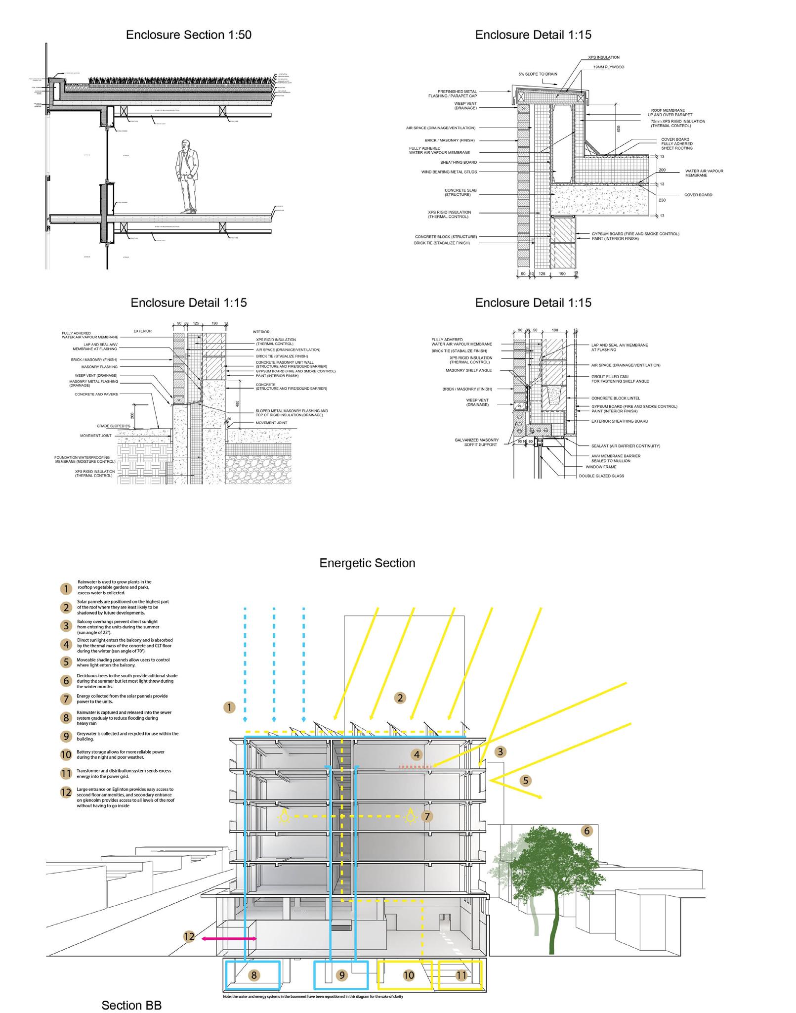
Project date: 2021 - Third Year Individual Project
The goal of this project was to increase the housing capacity of a region without damaging the existing street character. The bottom two floors contain the program of the original two-storey buildings while the five added floors accommodate new living units and accessible roof terraces.
The whole building steps down toward the nearby street so that the terraces can be accessed directly from the street.


The sculpture gallery is a space that arranges a series of elements to best frame an artist’s works and tools. It has contrasting spaces of interior/exterior, light/dark, and above/below. The building is situated between buildings on all four sides except the south. The gallery rests on the existing eastern building, leaves space for pedestrians to pass by to the north, and sandwiches a reflecting pool with the western building.
This was the final project done in studio after a series of related exercises. The gallery building can be broken up into three elements originating from movie clips selected at the beginning of the course.


The gallery was designed with multiple circulation paths in mind and frames views of the sculpture as the viewer approaches from one of 3 directions. The first thing the viewer sees regardless of the direction in which they approach the building is a piece of sculpture. If they come from the alley this takes the form of a cantilevered glass box with a sculpture inside. If the viewer comes from the south instead, they see a large stone shape resting directly on the ground. This first sculpture acts as signage and invites the passerby to come closer.
The gallery was designed with multiple circulation paths in mind and frames views of the sculpture as the viewer approaches from one of 3 directions. The first thing the viewer sees regardless of the direction in which they approach the building is a piece of sculpture. If they come from the alley this takes the form of a cantilevered glass box with a sculpture inside. If the viewer comes from the south instead, they see a large stone shape resting directly on the ground. This first sculpture acts as signage and invites the passerby to come closer.

As the viewer reaches the base of the building, they can then look at the sculpture placed on the reflecting pool. This can be done all at once through the north-south axis, or one at a time through the curved walls. The reflecting pool acts as a way to direct circulation, forcing the viewers to proceed through the colonnade beneath the main floor if they wish to see what is on the other side. Along with the white brick wall, the pool also helps reflect light into the tunnel under the building.
As the viewer reaches the base of the building, they can then look at the sculpture placed on the reflecting pool. This can be done all at once through the north-south axis, or one at a time through the curved walls. The reflecting pool acts as a way to direct circulation, forcing the viewers to proceed through the colonnade beneath the main floor if they wish to see what is on the other side. Along with the white brick wall, the pool also helps reflect light into the tunnel under the building.

The concrete supports curve over the viewer, stretching farther as they approach the center of the colonnade, where they point towards the entrance. Due to the depth of the walls, they block visibility when viewed at an angle. Light reflected off the pool and a white brick wall creates a gradient on the side of each concrete support. The gradient of light helps the viewer distinguish each curve, making the arching pattern even more visible.
The concrete supports curve over the viewer, stretching farther as they approach the center of the colonnade, where they point towards the entrance. Due to the depth of the walls, they block visibility when viewed at an angle. Light reflected off the pool and a white brick wall creates a gradient on the side of each concrete support. The gradient of light helps the viewer distinguish each curve, making the arching pattern even more visible.


This project, which preceded the “Sculpted Perspective“ was done in groups. The assignment was to design a “Heterotopia“, incorporating themes from films we had studied in an earlier project.
The image below shows the physical model our group built, and to the right Is the digital representation of what it might look like. The physical model was a group effort, the render was all done by myself.


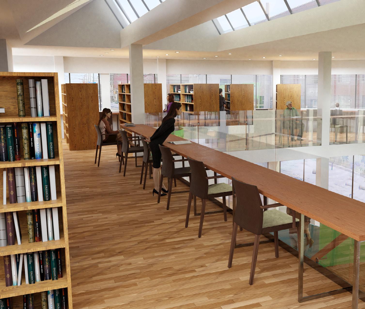
This project involved the documentation of a site, followed by the design of a small multipurpose library. I separated the library into a children’s space on the ground floor with curved wood and colors, and an adult space with flat walls and glass on the upper level.
Library a a


2019 - Second Year Individual
The aim of this project was to create a modular system to be used as a partition for an old storefront owned by the University and used as a public display space. I created an L shaped drawer that acted as storage as well as seating. I built one of the modules at full scale (image below).
The other images are renders I made showing what it would look like if I had made more of the modules. I modeled the inside of the store as it existed, then combined it with a picture I took of the outside to make it look realistic.


 photomontage
Competition entry I did independently. My intention was to submit for a rendering award available to students. Unfortunately, it turns out the competition was only open to students in 3rd year while I was in 2nd year.


The concept and design of the project was done together.
A bright orange tongue of flame reaches up towards the ancient cedars of Prince George, BC. A reminder of the constant threat of forest fires brought about by climate change.The bridge perches on the remains of a charred forest and roots heavily into the ashen ground using harsh and bulky steel connections and members. As the bridge begins to cross the river the sensation of the steel changes and the components are gradually made more slender and elegant. Its beak lands lightly in the old-growth forest leaving no bearing weight on its soil, while providing an accessible route up into the ancient trees and a number of resting stations for patrons to look out across the river and mark the contrast.
The Fire Bird takes the human footprint and renders it into steel, putting the impact into an unignorable perspective. The pointed shape of the bridge manipulates the perception of the viewers by creating converging lines to emphasize the vastness of old-growth trees in comparison with the absolute alien devastation of an uncontrolled wildfire. The use of longrunning tension members allows for a delicate 60m cantilever that only steel could hope to achieve.

The immense number of details that compose the Fire bird are very
designed using
finish
scale to lead the
at the
design intent is to celebrate the steel details that make a
of this scale and complexity possible and allow a hiker’s
to be impacted simply through the acts of walking and looking.
A: Mast Detail Fine
The details located on the westernmost bridge, and furthest into the cantilever, the most refined to create an extreme lightness to the floating end of are employed more frequently and filled.
AESS 4 is to be specified. Detail viewer (showcase elements). 300mm diameter tube HSS base mast
E: Walkway Structure Detail 1: 50
walkway consists of a thin grate which bears on a series of wide
is to
category
westernmost side of the cantilever, are by far extreme elegance and of the bridge. Welds and are remediated
Detail will be very close to base with 100mm solid
B: Mast Detail Medium
The intermediate masts make balanced use of bolting and welding and represent the transitionary point between the coarse and the fine detailing intended to change the experience through passage of the bridge and offer a new perspective.
AESS 3 to be specified. Detail will be viewed at <6m. 400mm diameter tube HSS base with 150 mm HSS mast
The masts located closest to the charred forest side of the bridge feature much more prominent and coarse detailing to emphasize the weight and bulk of the steel. They are intended to create a sense of gravity to the less cantilevered areas. Bolting is favoured over welding and all welds are left unremediated.
AESS 1 to be specified. Detail is viewed at a distance and intended to be rough and unrefined. 600-1000mm diameter tube HSS base with 200mm HSS mast.
D: Multi-Cable Connection Detail 1: 60 In order to align the forces and provide resistance in the right magnitude and vector the doubled cables are split and sent to two different foundation footings to root into the ground.
AESS 2 is to be specified. Detail will be viewed at moderate distance but due to its complexity requires more attention.
Layered 40mm steel cables are used for tension along with the 120mm connection plates
the mass and structure of the building is felt by the accetuate this feeling of lightness on the landscape.


The concept and design of the project was done together; I did the renderings and my partner did the line drawings.
The use of mostly bolt and pin connections throughout the stucture is an intentional de sign decision. Due to the large number of repeated members the use of bolts can save great amounts of time in construc tion. Bolts also accenctuate the mechanics of the stucture rather than hiding them
The Waverider waterfront pavilion seeks to recreate the turbulent and dynamic surface created by waves on water. The use of hollow steel framing and buoyant masses allow the pavilion to surf and follow the movement of the waves by moving large shells in synchronization with the individual crests. Cables stretched above and below the walkway as well as large steel boxes and spires give the user the experience of being on, in and below the water. Steel is generally perceived as being very heavy and poor at dealing with wet conditions, but Waverider aims to show that with specific construction and anti-corrosion materials steel can be made to even float on top of the water. The long spans that leave the underside of the walkway open for mechanisms are only achievable with the strength and support of steel, proudly displaying the unimitable qualities of steel.
Through light rings and small pieces of jingling steel the necessary components of the tensile structure are accen tuated. The turnbuckle and clamp grips are exaggerated and used to create the auditory effect of travelling under the water through their clinking.
The use of a round steel ring at the point of greatest tension playfully diverts the forces around a potential weak point in the tensile component of the structure. The large circle also creates an identifiable repeat ing figure for the underwater portion of the mobile cables.

The arrayed wave riding steel structures are allowed to move up and down but locked from moving side to side through the use of wheels with inset ridges. The mobile struc ture is able to follow the move ment of the waves vertically but restrained to one axis.

The use of mostly bolt and pin connections throughout the stucture is an intentional de sign decision. Due to the large number of repeated members the use of bolts can save great amounts of time in construc tion. Bolts also accenctuate the mechanics of the stucture rather than hiding them
Through light rings and small pieces of jingling steel the necessary components of the tensile structure are accen tuated. The turnbuckle and clamp grips are exaggerated and used to create the auditory effect of travelling under the water through their clinking.

The use of a round steel ring at the point of greatest tension playfully diverts the forces around a potential weak point in the tensile component of the structure. The large circle also creates an identifiable repeat ing figure for the underwater portion of the mobile cables.

Project date: 2022
Firm: 3XN
Role: 3D modeling/Rendering
This project is a student housing complex, where I worked with the project architects to create and update a series of renders used in order to get city approval. For this project, along with the render itself, I modeled the nearby context buildings for use by the other architects.


Project date: 2022
Firm: 3XN
Role: 3D modeling/Rendering
The project was done at 3XN, where I worked on the renders for the competition entry. The view on the left was done by myself, while other views contained 3D assets made by me.


Project date: 2021
Firm: Williamson Williamson
Role: 3D modeling/Rendering
The project was done at Williamson Williamson, where I worked along with the project architect to model the landscaping and wood siding, as well as produce both full-scale renderings and wooden (digital) small scale model renderings.


Project date: 2020
Firm: Williamson Williamson
Role: 3D modeling/Representation
I joined the project near the end of the design process. I helped the team settle on the finishing touches by making and modeling options of furniture, materials, and lighting. I then also created over a dozen final renderings, each with more than one lighting option (for example the three versions of the elevation on the right).
I also created an equal number of renders of a wooden (digital) scale model (for example the image below).


Project date: 2021

Firm: Williamson Williamson
Role: 3D modeling/Representation
Here I created a digital wooden scale model and rendered a series of images as seen on the right. I also did other types of representational diagrams for this project such as the section below.


Project date: 2020
Firm: Diamond Schmitt Architects

Role: 3D modeling/Rendering
I worked on all parts of making this render, including modeling a portion of the main building, and modeling all of the context. I also did all of the lighting, materials, and post-processing for this render.


2020
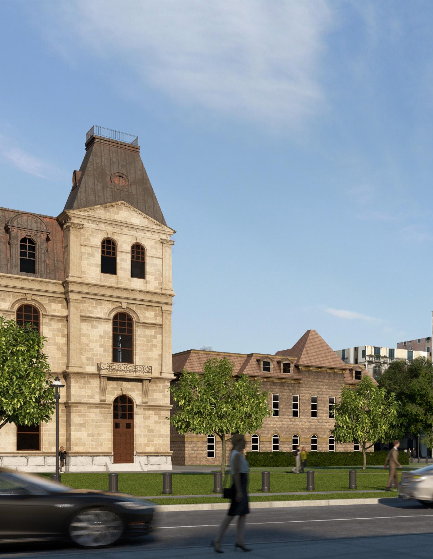
Firm: Diamond Schmitt ArchitectsOn this project, as a member of the rendering team, I modeled the existing heritage building beside our site in very high detail. I also did all of the context modeling and materials for the exterior views. The heritage building can be seen below.
For the interior views, I helped model the base geometry of the space. I also created a railclone script in 3ds max to create all of the seats, as well as fill each seat with a different person. This script also had the option to control the percentage of seats that were empty and would fold up empty seats.


Project date: 2020
Firm: Diamond Schmitt Architects
Role: 3D modeling/Rendering
For this project I modeled and rendered the interior, exterior, and context. Renderings where made to show to potential donors. I designed many quick iterations with inputs from the project architect.


Project date: 2018
Firm: CICADA Design, renders for Perkins & Will Role: 3D modeling/Rendering
The Confederation Line West is one of the three major extensions to Ottawa’s light rail transit system. CICADA Design was retained to provide digital renderings for the project.
As part of a team at CICADA Design, I rendered 5 images for each station - a total of over 85 views. I would receive comments on the renders from architects and make all the necessary changes.


Project date: 2020
On this project, I was in charge of doing the renders, as well as helping the architect model the roof of the main complex. Renders were created for the competition entry. There was a deadline of 2 weeks for making the renders, which included creating all of the surrounding landscape, as well as the existing waterfront conditions. For this project I was not involved in the design of the building itself.

While working on the materials for this project, I found some things that I thought were interesting. From low camera angles, to create convincing-looking water reflections, there need to be both areas of calm flat water as well as turbulent wavy water. To achieve this, I blended patches of both in my water material. Another interesting condition was the intersection of the rocks and water along the shore. In this case, I made another material that transitioned from a wet-looking rock to a dry-looking rock based on the distance from the water level.


 Aerial Drone Photography
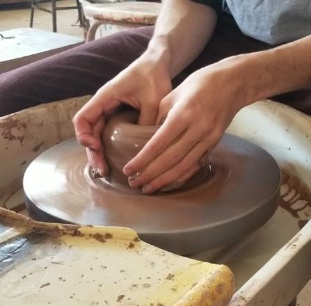
Pottery
Aerial Drone Photography
Pottery


