11 minute read
2. Mt Eden Main Works Description


2.1 Overview of Works
The main works involve construction along several active work fronts concurrently within the Mt Eden area at any one time, to enable the redevelopment of Mt Eden Station and establish the CRL tie-ins to the NAL. Works will be carried out in a staged fashion. The construction staging and methodologies are described in greater detail in the CEMP.
Within the main works area, there are already other works occurring in accordance with the Mt Eden Enabling Works (OPW60350039) and Normanby Road Early Works (OPW60351423) outline plan packages.
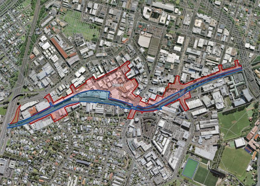
This ITA EMP has been prepared to address the entire main works area including works in the CRL and KiwiRail designations as outlined in Figure 2.1.
CRL Designation 2500-6 KiwiRail Designation 6300
Figure 2.1 Site and Extent of main works
In summary, the main works involve:
Ground improvements, in the form of deep soil mixing (contiguous piling and grout injection), within the NAL corridor between Mt Eden Road Bridge and Normanby Road; Bulk excavations and construction of retaining walls along the NAL to provide for the rail trenches and installation of new tracks. The excavation will encounter basalt, which will be removed via rock-breaking and blasting. In places, softer ground conditions are anticipated to be encountered, which may require the use of sheet piles;
Page 14
Mt Eden Main Works
Construction of the eastern and western crossover structures that enable the CRL rail lines to tie-in to the NAL; Construction of the Porters Avenue and Fenton Street pedestrian and cyclist bridges. Construction of the Normanby Road grade separation bridge, including regrading of Normanby Road and realigning the Boston Road roundabout; Redevelopment of the existing NAL platform; Construction of the CRL platform and the foundations and building structures for the Mt Eden Station building and the ventilation building; and Operation of the TBM, including the conveying of spoil material from the tunnels and the refuelling and general maintenance of the TBM within CSA 4.
This ITA EMP has been prepared to address cumulative effects where the enabling, early and main works overlap each other..
The main construction works are described in detail in the CEMP. The works will utilise two construction support areas (CSAs), namely CSA 4 at the Mt Eden Station location, and CSA 5 at the Normanby Road location.
There are a number of activities to be located at each CSA that are identified in this ITA EMP as high risk to stormwater and which will require management to mitigate the risk. These sources can be categorised as mobile throughout the works, or as fixed activities, and in either case controls will be identified to appropriately manage the risk.
CSA 4 will be used to support the Mt Eden Station construction and the tunnel boring operations. CSA 4 provides for tunnel segment storage, a spoil storage building, and site offices, as well as activities located within an area nominally referred to as the Technical Area adjacent to Shaddock Street. The Technical Area within CSA 4 will include a cooling plant, a bentonite plant, chemical storage areas, a water treatment plant, a tunnelling grout plant, workshops, air compressor units, and electrical transformers.
CSA 5 will be used to support the ground improvement works and other construction works at the Normanby Road end of the main works area, described in detail in the CEMP. The key plant and equipment supporting the works include a bentonite plant (during Stage 1), a soil mixing plant, muck bin for temporary spoil storage and a water treatment plant.
Site plans showing the site layouts and activities at CSA4 and CSA5 are shown in Figures 2-2 to 2-5.
The key ITA activities at each CSA are described in more detail in the following subsections.
Page 15
Mt Eden Main Works

Figure 2-2 CSA 4 Site Layout and Activities Page 16
Mt Eden Main Works

Figure 2-3 CSA 4 Technical Area –Site Layout and Activities Page 17
Mt Eden Main Works

Figure 2-4 CSA 5 Stage 1 Layout
Page 18
Mt Eden Main Works

Figure 2-5 CSA 5 Stage 2 Layout Page 19
Mt Eden Main Works
2.2 Tunnel Boring Machine Support Operations
The tunnel boring machine (TBM) will be launched from the Mt Eden CSA 4 area and travel approximately 2 kilometres to the Aotea station. Tunnelling support operations taking place within CSA 4 are outlined in Table 2.1 below. As the TBM progresses underground, precast concrete lining segments are applied to the tunnel interior using a grout which will be batched on the surface at CSA 4, in a grout batching plant.
The final grout mix comprises of an “A component” consisting of cement, bentonite, water and a “B component” consisting of Sodium Silicate Accelerator. The B component will be stored in the TBM Technical area in 1 m 3 intermediate bulk containers (IBC’s) and will be transported to the TBM using Multi Service Vehicles (MSV’s).
Table 2.1: Tunnelling Support Operations
Material Storage
Tunnelling materials preparation
Tunnelling grout
Cement powder, pulverised fly ash and bentonite will be delivered to the plant by trucks. Each material will be pumped to dedicated storage silo through hoses. Dust filters on the silos will be used to control dust emissions. Bunded containers of sodium silicate, grease, oil and ground conditioning foam will be stored in the Chemical Storage Area of the Technical Area. Raw materials from the A Component will travel to the mixer via a closed screw conveyor. The conveyor will have a protective cover to control dust. The raw materials and additives will be mixed intermittently with water in the required proportions and the grout will then be stored in a tank.
application
Transport of IBCs or drums of substances to the TBM Grout prepared in the grout plant will travel via pipe to the TBM and be pumped behind the tunnel linings to fill the annulus gap.
Spoil Disposal
Management of Discharges
The spoil removed by the TBM will be comprised of grout, water and soil, and will be carried by a covered conveyor out of the tunnel to the covered spoil store at the southern end of CSA 4 adjacent to the western railway line. It will be unloaded by excavators to the building and reloaded as required into trucks for authorised offsite disposal. The TBM grout plant will be bunded within the Technical Area. Any surface water collected in the bunded area will be pumped to the water treatment plant located within the Technical Area for removal of sediment, oil and treatment for pH prior to discharge to stormwater if it meets the required standards or to trade waste. There will be no gravity discharge of any water from the bunded area to the stormwater system. Any spilt material pumped to the water treatment plant will be treated as per other sediment laden water on-site, with discharge to stormwater only occurring once the minimum water quality standards are met.
2.3 Bentonite Plant
The D-wall construction as part of Stage 1 works requires the establishment of a bentonite plant at CSA 5 adjacent to Water Street. The bentonite plant will be located within a bunded area that drains to the water treatment plant. The purpose of the plant is to mix and recycle bentonite slurry associated with the D-wall construction. The plant comprises the following elements:
Bentonite plant:
Page 20
Mt Eden Main Works
Silos required for the storage of bentonite slurry for excavations; Silos for the storage of bentonite slurry for disposal; Bentonite mixer; Bentonite storage bags. Bentonite treatment plant: • • Slurry Treatment Plant (STP) / De-sanding Unit - with a capacity of approximately 450 m 3 ; Excavator. The bentonite plant operation is outlined in Table 2.2 and is shown on Figure 2.6.
Table 2.2: Bentonite Plant Operation
Bentonite Storage
Bentonite Mixing and Recycling
Spoil Disposal
Management of Discharges
Storage of bentonite powder and slurry within silos
Mixing of bentonite with water and additives (sodium bicarbonate and bentocryl) to make a bentonite slurry, which will be temporarily stored within the silos before being used in the piling and D-wall construction operations. The bentonite mixer will be covered to control bentonite powder dust emissions. Transfer of the bentonite slurry to the storage silo, which is connected to the circuit of the STP / de-sanding unit and down to the D-wall operations via pipes and hoses. Slurry will be pumped out from the trench and travel back to the de-sanding unit / STP, where it will be treated to remove solids and recover the slurry for re-use. Dry material recovered from the de-sanding unit will be removed off-site. Liquid spent slurry following de-sanding will be discharged into a bunded temporary spoil pit (approximately 24 m 3 ) to be located on site. The spoil will be excavated and transported via trucks (approximately 3-5 per day) to an approved disposal facility. The entire bentonite plant area will be bunded to contain any spilt material or bentonite slurry in the event of a pipe or pump failure during transfer of the slurry, as shown in Figure 2.. Any surface water collected in the bunded area will likely be disposed offsite (refer section 2.7.7 of the CEMP). Any spilt material pumped to the sediment control system will be treated as per other sediment laden water on-site, with discharge only occurring once the minimum water quality standards are met.
Page 21
Mt Eden Main Works

Figure 2.6: Bentonite Slurry Operation
Page 22
Mt Eden Main Works
A picture of the bentonite plant in place during the CRL Contract 1 construction works in lower Queen Street is provided in Figure 2.7 below to demonstrate the proposed bunding arrangement.
Figure 2.7: Bentonite Plant within Bunded area at CRL Construction Site in Lower Queen Street Page 23

Mt Eden Main Works
2.4 D-wall Construction
D-walls are constructed using a Hydrofraise cutter and will be used to establish the sides of the trench excavation for the railway tracks.
The Hydrofraise cutter performs excavation using bentonite slurry to stabilise the trench. The slurry is pumped out and travels back to the bentonite plant’s de-sanding unit, where it is treated to remove solids and recover the slurry for re-use –as described in Section 2.3 above. Following excavation comes the reinforcement stage, where spoil is progressively mucked away and reinforcement cages are inserted along with staged concrete pouring.
Excavated spoil from D-wall construction is stockpiled at the spoil pit adjacent to the site entrance off Water Street for CSA 5 prior to removal off site.
2.5 Soil Mixing Plant and Ground Improvement Works
There will be one soil mixing plant in place at CSA 5 only. The plant was established at the location shown in Figure 2.4 during the Normanby Road Early Works. The soil mixing plant will comprise the following elements:
Generator; Control room; Chemical storage; 80 tonne horizontal silo for cement powder storage; and Mixer (approximately 6m 3 ). The soil mixing plant combines water and cement and additional additives to create a slurry mix for in situ-ground stabilisation in the Active Construction Zone (ACZ). The ground stabilisation involves insertion of a large diameter auger into the ground while grout is injected through ports in the tooling. The injected grout is mixed using paddles on the auger that mix the ground and grout as it progresses down a column. Spoil generated during the deep soil mixing is collected and transported to the muck bin. The soil mixing plant operation is described further in Table 2.3
Table 2.3: Soil Mixing Plant Operation
Material Storage
Soil Mixing
In-situ ground stabilisation :
Spoil Disposal
Management of Discharges
Cement powder will be delivered to the plant by trucks. It will be pumped to the storage silo through hoses. Dust filters on the silos will be used to control dust emissions.
Cement powder will travel to the mixer via a closed screw conveyor. Cement powder will be mixed intermittently with water in the required proportions and the grout will then be stored in a tank. Grout will travel via hoses, filters and pumps to the pump, then to the soil mixing auger where it will be injected into the soil to form a soil-cement mix in situ.
The resulting sludge (made of grout, water and soil) will be pumped from the ground improvement works location to the muck bin at the north-eastern end of CSA 5. It will be mucked out onto trucks for transport to a suitable facility. The soil mixing plant is contained in a bunded area. Any surface water collected in the bunded area will be pumped to the water treatment plant located near the CSA 5 site entrance off Water Street, for removal of sediment
Page 24
Mt Eden Main Works
and treatment for pH prior to discharge. There will be no gravity discharge of any water from the bunded area to the stormwater system. Any spilt material pumped to the water treatment plant will be treated as per other sediment laden water on-site with discharge to stormwater only occurring once the minimum water quality standards are met.
Page 25
Mt Eden Main Works
