CRL Contract 3
Aotea Utility Relocation Works
Erosion and Sediment Control Management Plan
Addendum to: Albert Street Canopy Removal and Utility Relocation Erosion and Sediment Control Management Plan
CRL-SYW-CST-ATMWP-REQ-001249
Revision: 0 30 August 2019
Page 1 | Erosion and Sediment Control Management Plan

Erosion and Sediment Control Management Plan
CRL-SYW-CST-ATMWP-REQ-001249
This document is uncontrolled when printed. This document should be printed in colour
Status
Approval Status
Name/Title Signature
Prepared by: Ellen Chang Graduate Civil Engineer
Reviewed by: Alisdair Simpson Senior Planner
Controlled by: Duane Rollo Associate Director – Civil Infrastructure
Approved by: Peter Roan Consents Lead – Link Alliance
1. Introduction
1.1 Overview
The City Rail Link (CRL) project comprises the construction, operation and maintenance of a 3.4km underground passenger railway, running between Britomart Station and the North Auckland Line (NAL) in the vicinity of Mt Eden Station. The CRL project includes the construction of twin underground rail tunnels and two underground stations up to 42 metres below ground. Due to the complex nature and substantial size of the project, multiple work packages are being progressed.
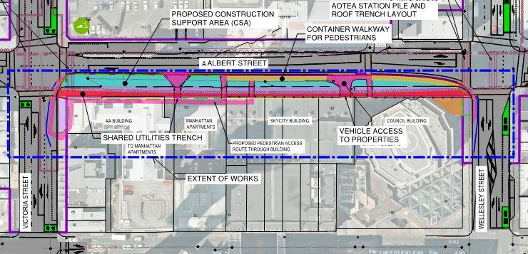
Utility relocation works are required prior to the main construction activities around Aotea Station. The relocation of utilities between Victoria Street and Wellesley Street along the west side of Albert Street have been previously authorised as shown in Figure 1 below. The propose d works along Albert Street between Wyndham and Victoria Streets, with works extending into parts of Kingston Street and Victoria Street West, require further authorisation. These works are also shown in
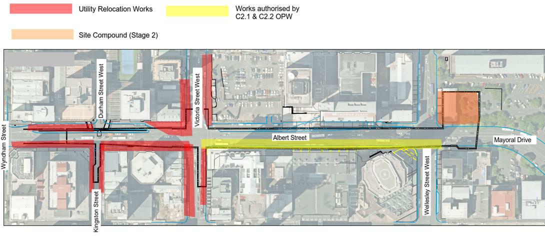
The works are to be broken down into three stages.
Figure 1.
Figure 1 Area of proposed works authorised works
1.2 Purpose and Scope
This addendum updates the “Albert Street Canopy Removal and Utility Relocation Erosion and Sediment Control Management Plan” dated 10th May 2018, prepared by Aurecon New Zealand Ltd (Aurecon), henceforth referred to as the Approved ESCP.
The Approved ESCP was required by CRL Designation 1 and the Aotea to North Auckland Line (A2N) Regional Land Use Resource Consent (R/LUC/2016/1890) and assessed all temporary works required for canopy removal and utilities diversion on the western side of Albert Street, from Wellesley Street to Victoria Street West. Additional works are required beyond the footprint of the Approved ESCP.
This Addendum to the Erosion and Sediment Control Plan (ESCP) describes the principles and practices to be implemented to manage the adverse effects of sediment discharges from the proposed works which are beyond the scope of the existing authorisation. This addendum must be read in conjunction with the Approved ESCP. The additional Utility Relocation Works Site Area assessed under this addendum are described in section 2 below.
1.3 Report Structure
No proposed change to this section in the Approved ESCP.
2. Project and Site Description
2.1 General
The works involve the relocation of electrical, telecommunication, gas , potable water, stormwater and wastewater assets located in Albert Street, Kingston Street and Victoria Street West.
It is anticipated the works will take approximately 6 months to complete. Should complexity or additional services be encountered during the course of the works then this duration may be extended
2.2 Key Phases and Considerations
It is proposed to undertake the utility relocation works in 3 stages. For all stages the main element of the works is the formation of temporary trenches within footpaths to allow installation of new cable ducts and pipes for utility services. Once the ducts and pipes are installed the trenches will be backfilled and the footpath reinstated. The trenches will be 1m to 1.8m in width and around 1.5m to 3m deep.
Table 1 below describes the utility relocation works in more detail. The construction methodology and sequencing defined in Section 2.6 (page 6), of the Approved ESCP, are applicable to the works summarised in Table 1.
Table 1: Utility Relocation Works Summary
Trenching along Victoria Street will be to a depth of 1.5m. All other trenches will be around 2.5m to 3m in depth. The total length of trenches constructed will be approximately
Stage 1
Works will be located along the footpaths of Albert Street, between Wyndham Street and Victoria Street, extending into part of Kingston Street and Victoria Street, and on the northern Albert Street Slip lane.
Stage 2
Stage 3
340m resulting in approximately 1,350m³ of spoil being removed.
Works will be located along the footpath of Victoria Street, between Albert Street and Elliott Street (on the south side of the street) with trenching being around 1.5m in depth.
Between Victoria Street and Kingston Street, on the western side of Albert Street, trenching will be around 2.5m in depth.
A support site compound will be provided in part of the car park of Bledisloe House (details provided below)
The total length of trenches constructed will be approximately 160m resulting in approximately 480m³ of spoil being removed.
Works will be located along the east side footpath of Albert Street (between the top of the ramp from Durham Street to the corner of Victoria Street) and the north side footpath of Victoria Street, between Albert Street and Elliott Street. Works will also be undertaken on the north side of Victoria Street, between Federal Street and Albert Street.
The total length of trenches constructed will be approximately 180m resulting in approximately 585m³ of spoil being removed.
Total length of 680m of trench resulting in approximately 2,415m³ of spoil being removed.
2.3 Site Layout
2 months (November 2019 – December 2019)
1.5 months (December 2019 / January 2020 –March 2020)
Approx. 6 months
The location and extents of the construction site area are shown in Figure 2 and on drawings CRLAOT-ERO-000-SKE-0001 to 0004 included in Appendix C
The construction site area is located in Auckland City Centre, within the road corridors of Albert Street, Victoria Street West and Kingston Street (as illustrated in Figure 2).
2.4 Site Levels and Catchments
There is no change to the existing text in Section 2.4 of the Approved ESCP. The following text is added to the section to describe the Stage 1-3 utility relocation works:
Victoria Street West is currently serviced by existing catchpits that are connected to an existing stormwater system and slopes downhill towards Queen Street.
Kingston Street is also serviced by existing catchpits that connect to an existing stormwater system.
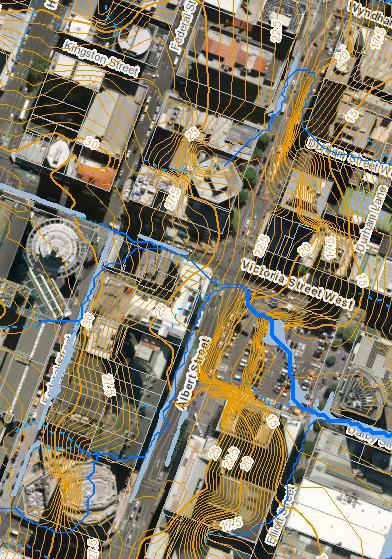


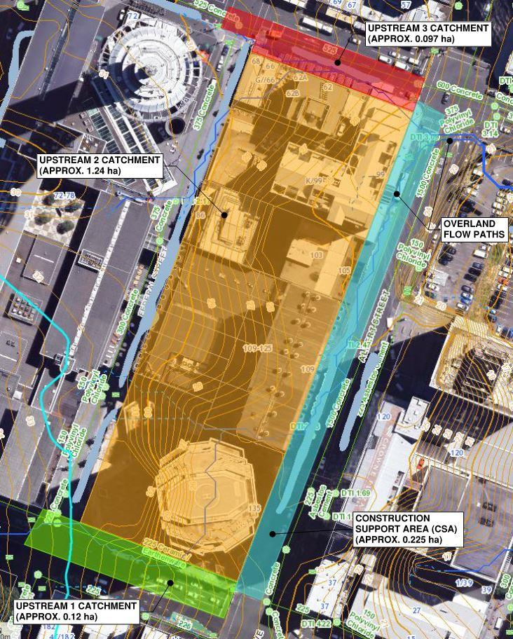
Figure 2: Overland Flow Paths in the Additional Works Area (Pink and Purple) and Initial Project Area (Green)
2.5 Site Overland Flow Paths
No proposed change to this section in the Approved ESCP.
2.6 Construction Related Works
2.6.1. Canopy Removal / Cut -backs
No proposed change to this section in the Approved ESCP.
2.6.2. Utilities Relocation
No proposed change to this section in the Approved ESCP.
2.7 Site Management
2.7.1.
Establishment
A temporary construction site compound (Figure 3) will be formed on the corner of Wellesley Street and Mayoral Drive in the part of the Bledisloe House car park. This compound will be within the project designation boundary and will be established approximately from October 2019 (Stage 2), until March 2020. This site compound will be occupied by storage containers, the objective of the site compound is to provide a site that can be used as a rest area for workforce staff, and house equipment and vehicles during the works. Temporary fencing will be used to delineate the site, along with Link Alliance branded mesh scrim. Vehicle access will be via the existing entrance off Mayoral Drive and through the gate as marked on the plan. Containers are likely to include machinery equipment and a total of up to 1,200L (6x 20L drums) of diesel in bunds.
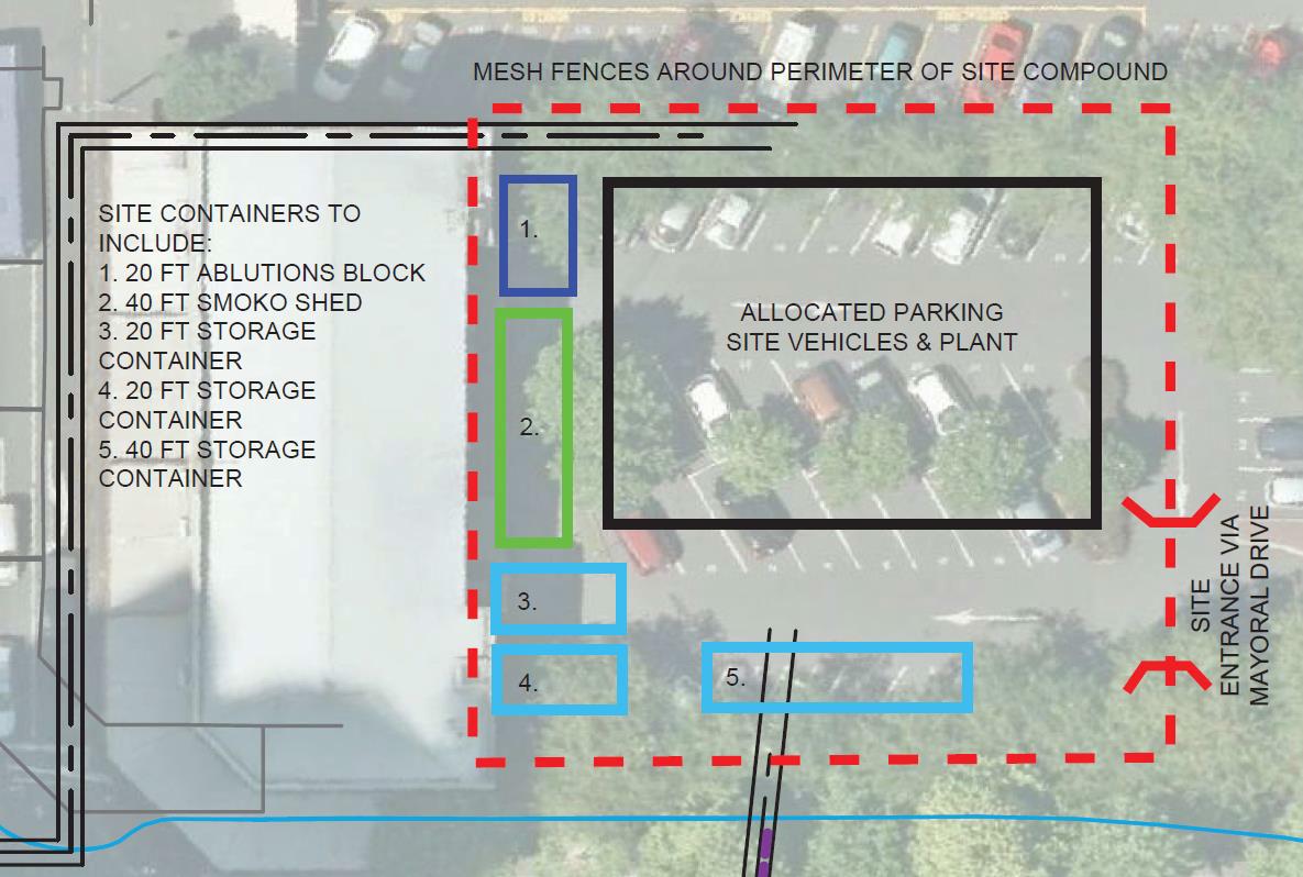
Figure 3: Indicative layout of the Stage 2 Site Compound
Detailed site layouts for each stage of the works have been provided in Appendix C of the CEMP addendum which also informs the location of the construction site compound.
With the exception of the above, no change is required to this section of the Approved ESCP.
2.7.2.
Provision of Access
An alternative access route will be provided for pedestrians during the construction works as detailed in the TAPDWP (Appendix E of the CEMP).
2.7.3. Storage and Site Activities
Material removed from the site will predominantly consist of the following:
· Excavation of trench using hydro-excavation (~1,200m 3); and
· Excavated materials during formation of shared utilities trench (~ 1,215m3)
The following text is provided from the Approved ESCP for clarity of the storage and site facilities to be provided:
It is proposed that the excavated slurry material (using hydro -excavation) is immediately pumped and loaded into the hydro-excavation truck. Whilst material removed using excavators is also to be loaded directly into waiting trucks and disposed offsite as early as possible. Any spoil that sho uld be stockpiled temporarily shall be stored on the up-slope side of the trench if possible or in a stabilised area which is away from the overland flow paths or within 1m of hazard areas such as kerb and channels, stormwater inlets, paved footpaths or driveways.
It is expected that approximately 20 linear metre of trench will be excavated per day, which is approximately 45m3 per day. This material will be placed directly into trucks and disposed offsite immediately Provision has also been made to allow for storage of pipelines and ducts onsite.
The following site activities are envisaged while carrying out the construction related works mentioned in Section 2.6:
· Earthworks from controlled disturbed areas;
· Disposal of excavated spoil off -site;
· Construction / demolition waste is likely to be stored in skips and removed on a regular basis as required;
· Concrete trucks are likely to be washed out, off -site;
· Hazardous construction materials (if any) are proposed to be stor ed in an isolated area designated for this purpose;
· Loading and unloading of construction materials from trucks;
· Storage for construction materials, such as geotextiles, formwork (timber and steel), petrol (including diesel);
· Waste storage and collection;
· Separation of excavated material from slurry generated using Hydrovac;
· Importation of backfill material; and
· Construction of groundwater and stormwater collection, treatment measures and connections to existing network.1
1 Approved ESCP
3. Erosion and Sediment Control
3.1 Design Philosophy
No proposed change to this section in the Approved ESCP.
3.2 Design Principles
No proposed change to this section in the Approved ESCP.
3.3
Earthworks
The approximate earthworks volume for the shared utilities trench installation and removal of abandoned utilities is 2415m3. All material excavated is expected to be loaded straight onto trucks. However, if materials are to be stockpiled on site temporaril y before removal offsite then a designated stockpile area as shown on the drawings shall be used. All volumes are estimated in -situ with no allowance for bulking.
3.4 Settlement Tank Sizing
It is anticipated that the groundwater table at the site is below the bottom of the shared utilities trench and therefore, only a minimal groundwater ingress is expected into the trench. Refer to the Groundwater Monitoring and Contingency Plan, attached as Appendix L of the CEMP addendum report with regards to the potential for, and management of, groundwater at the worksite. Table 2 below provides a summary of inflows and settlement tank volume required for a worst-case scenario where up to half the total length of the trench is open.2
Settlement tanks have been sized for each stage of works described in Table 1. The summary of proposed settlement tank volume is listed in Table 2
Table 2: Summary of Proposed Settlement Tank Volume for Each Construction Stage
* The recommended tank volume applies to the total area of each stage
** Open Excavation Area is based on a trench width of 1.5m, and the length of trench provided by the contractors.
***Volume for Stormwater Management applie s to each stage and is not the cumulative value of all the stages listed in the row.
**** Minimum settlement tank volume has been calculated using a conservative approach of 2% of the open excavation area
Auckland Council’s TP108 guideline was used to estimate the stormwater flow entering the construction area. In accordance with Auckland Council’s Erosion and Sediment Control Guideline (GD05) a 10-year Average Recurrence Interval (ARI) stormwater flow with 24-hour duration and a
2 Approved ESCP
climate change factor of 13.2% was used in the design of the settlement tanks. Thus, the 6hr 1 in 5year storm event, as prescribed by the ISCA Sustainability Rating System is complied with.
The management system is proposed to consist of two in -line settlement tanks. The first tank will be the discharge tank for the pumped discharge and the other will provide secondary settlement prior to discharge to the stormwater system. Given the extent of earthworks, flocculent treatment would not be required for the Project.
Settlement in both tanks will be monitored throughout the construction period and sediment will be regularly removed as required to ensure optimum management in maintained.
It is noted that if stormwater/groundwater flows e xceed the maximum pump rate the open excavations will be inundated. As no groundwater in-flows are expected, and surface flows from upstream catchments have been diverted around the site, the risk of dirty water from the excavations overtopping the trench and discharging uncontrolled is considered low. It will be the responsibility of the contractor to appropriately manage the construction site during storm events.3
3.5 Erosion and Sediment Control Measures
No proposed change to this section in the Approved ESCP.
3.6 Monitoring
No proposed change to this section in the Approved ESCP.
4. Conclusion
Staging and progressive stabilisation of the area will reduce the potential for erosion and sediment discharges from the utility relocation works.
This ESCP provides a framework for identifying and implementing erosion and sediment yields during construction works. A design philosophy and a number of design principles have been provided, along with specific control methodologies for the Project works.
The proposed sediment and erosion controls have been developed in such a way that they align with the proposed construction methodology. All controls shall be fully established before any physical works are undertaken and monitored in accordance with the Auckland Council GD05 (June 2016).4
Based on the proposed erosion and sediment controls detailed within this report, the effects of sediment discharges resulting from the utility relocation works will be managed in accordance with the best practicable option.
3 Approved ESCP
4 Approved ESCP
Appendix A:
Glossary of Abbreviations
No proposed change to this section of the Approved ESCP.
Appendix B:
Glossary of Terminology
No proposed change to this section of the Approved ESCP.
Drawings Appendix C:


NOTES:
1.FOREROSIONANDSEDIMENTCONTROLMEASURE STANDARDDETAILSREFERTOGUIDELINE DOCUMENT005.
2.STABILISEDENTRANCEWAYSAREREQUIREDATANY ENTRYOREXITPOINTOFACONSTRUCTIONSITE.
3.ALLDRAWINGSSHALLBEREADINCONJUNCTION WITHAOTEASTATIONSTAGE1TO3UTILITY RELOCATIONWORKSESCPANDCEMP.
4.ALLAREASAREINDICATIVEONLY.


TOANEXISTINGSWMANHOLE.THE MANHOLENEEDSTOBEPROTECTED FORPUBLICSAFETY.


1.FOREROSIONANDSEDIMENTCONTROLMEASURE
2.STABILISEDENTRANCEWAYSAREREQUIREDATANY ENTRYOREXITPOINTOFACONSTRUCTIONSITE.
3.ALLDRAWINGSSHALLBEREADINCONJUNCTION WITHAOTEASTATIONSTAGE1TO3UTILITY RELOCATIONWORKSESCPANDCEMP.
4.ALLAREASAREINDICATIVEONLY.


1.FOREROSIONANDSEDIMENTCONTROLMEASURE
2.STABILISEDENTRANCEWAYSAREREQUIREDATANY
3.ALLDRAWINGSSHALLBEREADINCONJUNCTION WITHAOTEASTATIONSTAGE1TO3UTILITY


1.FOREROSIONANDSEDIMENTCONTROLMEASURE STANDARDDETAILSREFERTOGUIDELINE DOCUMENT005.
2.STABILISEDENTRANCEWAYSAREREQUIREDATANY ENTRYOREXITPOINTOFACONSTRUCTIONSITE.
3.ALLDRAWINGSSHALLBEREADINCONJUNCTION WITHAOTEASTATIONSTAGE1TO3UTILITY RELOCATIONWORKSESCPANDCEMP. 4.ALLAREASAREINDICATIVEONLY.


SETTLEMENTTANKSTODISCHARGE TOANEXISTINGSWCATCHPIT.THE CATCHPITNEEDSTOBEPROTECTED FORPUBLICSAFETY.
1.FOREROSIONANDSEDIMENTCONTROLMEASURE
2.STABILISEDENTRANCEWAYSAREREQUIREDATANY ENTRYOREXITPOINTOFACONSTRUCTIONSITE.
3.ALLDRAWINGSSHALLBEREADINCONJUNCTION WITHAOTEASTATIONSTAGE1TO3UTILITY RELOCATIONWORKSESCPANDCEMP.
4.ALLAREASAREINDICATIVEONLY.


1.FOREROSIONANDSEDIMENTCONTROLMEASURE
2.STABILISEDENTRANCEWAYSAREREQUIREDATANY
3.ALLDRAWINGSSHALLBEREADINCONJUNCTION
4.ALLAREASAREINDICATIVEONLY.
Certified ESCP Appendix D:


Table 1 - Appropriate areas and earthworks volumes for C2.2 Utilities relocation 9
Table 2 - Summary of proposed shared utilities trench groundwater inflow rates and rainfall volumes10
1 Introduction
1.1 Overview
City Rail Link Limited (CRLL) is the requiring authority responsible for the construction of the City Rail Link (CRL) in accordance with the conditions of the CRL Designation 1714. The works associated with the Albert Street Canopy Removal (C2.1) and Utility Relocation (C2.2), which is referred as the Project in this report, are authorised by CRL Designation 1714 and the CRL Aotea to North Auckland Line regional resource consents1 (A2N resource consents). The main purpose of the Project is to streamline a critical path activity for the future construction of Aotea Station.
This report outlines the Erosion and Sediment Control Management Plan (ESCP) for the Project, taking into consideration the conditions of the A2N resource consents. The works are related to the removal or cut-back of 4 No. of building entrance canopies and the relocation of existing utilities along the western edge of Albert Street. The Project will be executed along approximately 220m of road frontage, along and directly in-line with an existing pedestrian walkway and will extend into the Victoria Street and Wellesley Street intersections with Albert Street, in order to connect the existing utilities with the new re-aligned utilities. Refer Figure 1 below.
Figure 1 – Location and extent of the Project
This ESCP has been developed by Aurecon New Zealand Limited (Aurecon) to describe the proposed erosion and sediment control measures and practices to minimise the effects of construction activities of the Project on the receiving environments.
The ESCP provides a methodology and management approach which confirms that the Project can be implemented in a controlled manner, ensuring that impacts on the environment from sediment and erosion are less than minor. Requirements associated with making any amendments to this ESCP (if required) will be detailed in the Construction Environmental Management Plan (CEMP).
The ESCP is an appendix to the CEMP which has been prepared as required by A2N resource consent conditions 53-58. We note that the content of this report has been written with reference to the ongoing detailed design.
1 Auckland Council reference R/LUC/2016/1890, R/REG/2016/1892, R/REG/2016/1895, R/REG/2016/1896, REG/2016/1897, R/REG/2016/1898, R/REG/2016/1899, R/REG/2016/1900 and R/REG/2016/2038
1.2 Purpose
The purpose of this ESCP is to fulfil the A2N resource consent condition compliance requirements for mitigation and management of erosion and sedimentation related effects. It outlines the control measures to be implemented within the construction support area (CSA) by the contractor to manage erosion and sediment in line with the relevant legislative requirements as stated in the CRL designation condition #21.1 (b) and (c).
This ESCP shall be read in conjunction with the Aotea Station Utilities Management Plan CRL-AOTUTI-000-PLN-0010 (particularly Section 4 and Appendix I: Preliminary design drawings) and the Construction Environmental Management Plan (CRL-PAT-RME-000-RPT-0100). These two documents define the design and construction methodology for the Project.
1.3 Scope
This ESCP provides a summary of the proposed erosion and sediment control measures relevant to the Albert Street Canopy Removal and Utility Relocation. It relates to all temporary works required for the following (refer Figure 1):
Removal or cut-backs of 4 No. of building canopies attached to the existing buildings on the western side of Albert Street;
Construction of new shared utilities trench along the western footpath of Albert Street;
Connections to existing utility networks at the Victoria and Wellesley Street intersections with Albert Street;
Removal of existing utilities made redundant by the installation and connection of the new utilities.
The implementation and monitoring of controls discussed within this ESCP are in accordance with Auckland Council (AC) Guideline Document 2016/005 “Erosion and Sediment Control Guide for Land Disturbing Activities in the Auckland Region.”
Technical reporting for groundwater, contaminated land, water quality, noise pollution and air quality matters are addressed by separately in the Construction and Environmental Management Plan.
1.4 ReportStructure
The structure of the ESCP is designed to provide a logical and practical framework for the management of erosion and sediment control measures as it relates to the Project. The ESCP has the following key sections:
Section 2 provides the Project general description, key phases and considerations, a detailed description of the site (also referred as CSA) and the required construction related works;
Section 3 provides a detailed description of the erosion and sediment control measures proposed for the CSA;
All drawings referenced throughout the report are attached in Appendix C of this report.
2 Project and Site Description
2.1 General
The Project works involve the removal of canopies attached to existing buildings on the western side of Albert Street between Victoria Street and Wellesley Street as well as relocation of existing utilities under the western footpath into an isolated, shared utilities trench located between the property boundary line and the western edge of the future station pile wall. It includes disconnection of utilities from existing network and connection to the new network installed within the shared utilities trench.
The following 4 No. of building canopies need to be removed prior to the construction of shared utilities trench:
99 Albert Street (AA Building)
105 Albert Street (Manhattan Apartments)
109-125 Albert Street (Sky City Building)
135 Albert Street (Auckland Council Building)
The realigned utilities within the shared utilities trench include: Stormwater pipeline; Wastewater pipeline;
Potable water supply main;
Ducts for high voltage (HV) and low voltage (LV) cables; Ducts for telecommunication cables.
The width of the shared utilities trench varies between 1.15m and 1.85m, with total length of approximately 220m. Due to the depth of the existing stormwater and wastewater lines, this trench needs to be 4.0m deep. Hydrovac is used to expose ground up to 1.5m depth to ensure the existing utilities or connections are identified, isolated and protected prior to excavating another 2.5m deep using an excavator.
The location of the shared utilities trench is selected based on the level of accuracy of the information gathered for the existing underground utilities. Therefore, if any clash is identified on site, the relevant NUOs and the Engineer are to be notified for further directions.
The detailed design for Contract C2.2 utilities relocation is still to be completed in coordination with the relevant NUOs.
2.2 KeyPhasesandConsiderations
The following are some key phases to be considered for the Project:
In order for Contract C2.2’s utilities relocation works to commence, the existing utilities, particularly Chorus cables need to be diverted away and via Federal Street as these utilities are currently along the proposed shared utilities trench location. These diversion works are currently being selfperformed by the NUOs;
Federal Street Diversion of utilities including civil works (ducts and pits), hauling of cables through new ducts and cutovers from the existing network to the new network are to be completed prior to commencement ofC2.2 works;
Detailed design for C2.2 to be completed in coordination with the relevant NUOs;
C2.1 and C2.2 Construction works are anticipated to take approximately 15 months based on the Contractor and CRLL’s best knowledge of underground services. Should additional complexity or additional underground services be encountered during the course of the Project, then the Project duration will extend beyond 15 months;
, Works are expected to commence in January 2018; and
This Project is viewed by CRLL as enabling works, which first need to be completed before work on Aotea Station (in this area) can commence.
2.3 SiteLayout
The location and extents of the CSA are shown in Figure 1 and on drawing CRL-AOT-UTI-000-DRG0101 included in Appendix C.
The CSA, approximately 2250m2, is occupied by the entire western footpath and the carriageway up to the centreline of Albert Street, between Victoria Street and Wellesley Street. As a result, this will require lane(s) closure and provision of an alternative pedestrian access route. Temporary vehicle access to properties will also need to be established during construction. Refer to Transport, Access and Parking Delivery Work Plan attached as Appendix E of the CEMP report for details.
2.4 SiteLevelsandCatchment
The CSA is located on relatively flat ground which falls from approximately RL 27.0m at the southwest corner (from Wellesley St intersection) and RL 25.0m at the northwest corner (from Victoria St intersection) towards a low point on the western kerbline outside property 99 Albert Street (AA building) at approximately RL 24.0m where a double catchpit exists. The CSA has an upstream catchment of approximately 1.452ha (refer Figure 2). Approximately 85% of the runoff from this catchment is contained within the existing buildings and conveyed directly into the local stormwater network. The remaining upstream catchment from Wellesley Street and Victoria Street is contained within the road corridor and conveyed to inlets at either side of the CSA. Therefore, flows from this external catchment are not shown to enter and will continue to be excluded from the site during construction. Surface runoff from the CSA itself drains to the existing catchpits located on the western site of Albert Street, a standard catchpit is located outside 109-125 Albert Street (Sky City Building) and a double catchpit is located outside 99 Albert Street (AA building).
2.5 SiteOverlandFlowPaths
Auckland Council GIS shows the location of the CSA conflicts with the Overland Flow Path (OFP) from the upstream catchments and is predicted to be inundated by surface water as a result of 1 in 100 year rainfall event (refer Figure 2). However, the upstream catchments are managed and conveyed within the local stormwater network, resulting in minimal surface runoff entering the CSA during the majority of storm events. In addition, the topography of Wellesley Street and Victoria Street is in such
Figure 2 – CSA overland flow paths and upstream catchment (retrieved from Auckland Council GIS 03/10/17)
a way that the surface runoff from these streets will be generally directed further down the intersection towards Queen Street.
2.6 ConstructionRelatedWorks
2.6.1 CanopyRemoval/Cut-backs
The canopy removal or cut back works, specifically the extent of removal, is different for each building, however there are common methodologies that will apply to each stage, and similar tools and techniques will be used throughout, as mentioned below:
Terminate any and all power supplies to the canopy and relocate any and all plant, equipment and signage currently located on those parts of the canopy to be removed;
Erect scaffold, dismantle and remove building canopy or cut-back to agreed position;
Remove glazing/panel/roof sections,
Remove roof/secondary supports between main support beams, and
Remove primary support beams.
Install weatherproof flashing to building façade where required and make good.
2.6.2 UtilitiesRelocation
Following canopy removals or cut-backs, below ground works will commence for the installation of the utilities within the shared utilities trench as listed:
The construction of the shared utilities trench is proposed to commence from north (Victoria Street/Albert Street intersection) and progressing towards the south (Wellesley Street/Albert Street intersection);
Mark out proposed footprint of trench selection. Identify and locate existing utilities on surface;
Saw cut and remove existing footpath pavement (pavement is primarily asphalt surfacing, with isolated granite tile inserts);
Expose up to 1.5m depth using hydro-excavation and locate all existing utilities within the western footpath as well as existing building foundations along boundary to confirm extent and/or clash with proposed shared utilities trench;
Locate, protect and isolate all existing utilities on site for further excavations;
Excavate trench to maximum 4m depth using excavator. Care to be taken for working around struts and utilities. Provide temporary strutting and shoring to trench sides with timber or trench shield as appropriate;
Install new stormwater and wastewater pipelines and manholes starting at downstream end and working south. Cut over building connections to newly installed system once downstream is installed and connected to existing network;
Install polystyrene wall adjacent to eastern side of trench (western side of future station pile to act as a guide wall for future piling);
Backfill approximately half trench depth and install a new potable water supply main closer to the eastern side of the shared utilities trench;
Lay new ducts for power and telecommunication cables, place and compact trench backfill where possible. Excavation for draw pits and joint bays and connection points to be left open. This section of the work includes power and communication outages, which will be planned and coordinated with building occupants, to minimise disruption;
NUOs to haul new cables through the new ducts and cutover existing network to new network; Place bedding material and compact remaining sections of ducts; Remove abandoned utilities that are within the western footpath; and
Backfill and reinstate footpath to match existing levels and surface.
2.7 SiteManagement
2.7.1
Establishment
Preparation of the site will involve the following activities:
Temporary traffic management (refer Appendix E of the CEMP report for details);
Erosion and sediment control measures as detailed in Section 3 and on the drawings attached in Appendix C of this report;
Installation of temporary fences and hoardings along site boundary and designation of entry and exit locations;
Establishment of barriers and hot-mix diversion bunds along the boundary of the CSA;
Establishment of site amenities, offices and storage areas; and
Location and protection of existing utilities.
2.7.2
ProvisionofAccess
An alternative access route for pedestrians will be provided either through containers or via the undercroft of the buildings. Existing vehicle access to properties 105 Albert Street (Manhattan Apartment) and 109-125 Albert Street (Sky City Building) will be maintained and controlled by Traffic Controllers (TCs).
2.7.3
StorageandSiteActivities
Material removed from the site will predominantly consist of the following:
Excavation of trench using hydro-excavation (~540m3); and
Excavated materials during formation of shared utilities trench (~900m3).
It is proposed that the excavated slurry material (using hydro-excavation) is immediately pumped and loaded into the hydro-excavation truck. Whilst material removed using excavators is also to be loaded directly into waiting trucks and disposed offsite as early as possible. Any spoil that should be stockpiled temporarily shall be stored on the up-slope side of the trench if possible or in a stabilised area which is away from the overland flow paths or within 1m of hazard areas such as kerb and channels, stormwater inlets, paved footpaths or driveways.
It is expected that about 7 linear metre of trench will be excavated per day, which is approximately 20m3 per day. About 90m2 of temporary spoil storage area is proposed at the CSA as shown on the drawings. Any such material stored on site will be covered by geotextile fabric during inclement weather to reduce sediment runoff and dust migration. Provision has also been made to allow for storage of pipelines and ducts onsite.
The following site activities are envisaged while carrying out the construction related works mentioned in Section 2.6:
Earthworks from controlled disturbed areas;
Disposal of excavated spoil off-site;
Construction / demolition waste is likely to be stored in skips and removed on a regular basis as required;
Concrete trucks are likely to be washed out, off-site;
Hazardous construction materials (if any) are proposed to be stored in an isolated area designated for this purpose;
Loading and unloading of construction materials from trucks;
Storage for construction materials, such as geotextiles, formwork (timber and steel), petrol (including diesel);
Waste storage and collection;
Separation of excavated material from slurry generated using Hydrovac;
Importation of backfill material; and
Construction of groundwater and stormwater collection, treatment measures and connections to existing network.
3 Erosion and Sediment Control
3.1 DesignPhilosophy
The construction environment of the Project related works is a highly developed urban environment predominantly formed of hard impervious paved areas and buildings. Given the nature of the surrounding environment and the proposed direct disposal of the spoil material offsite, sediment generative activities shall be largely contained within the excavations themselves. In addition, maintaining controls within the excavation will result in minimal effect on the surface and the surrounding built environment.
3.2 DesignPrinciples
Erosion and sediment control measures will be established to minimise the extent of soil erosion and sediment yield from the CSA during construction. It will be implemented and monitored in accordance with AC “Erosion and sediment control guide for land disturbing activities” in the Auckland Region, known as GD05. This GD05 is an update of AC Technical Publication 90 (TP90) “Erosion and sediment control guidelines for land disturbing activities” in the Auckland Region and supersedes that guideline.
All silt control measures shall be fully established throughout the CSA before physical works proceed in that area. The removal of the silt control devices and the reinstatement of the surrounding ground upon completion of the works shall form part of the civil component of the Project works and will be managed by the contractor.
3.3 Earthworks
The approximate earthworks volumes for the shared utilities trench installation and removal of abandoned utilities are summarised in Table 1. All material excavated are expected to be loaded straight onto trucks. However, if materials are to be stockpiled on site temporarily before removal offsite then designated stockpile area as shown on the drawings shall be used. All volumes are estimated in-situ with no allowance for bulking.
Table 1 - Appropriate areas and earthworks volumes for C2.2 Utilities relocation
*Excavatedslurrymaterialisconstantlyloadedintothetruckasitisexcavated.
**Referstoabandoned utilities underthewesternfootpaththatarewithin1.5mdepthonlyandexcavatedusing hydro-excavation.Removalofallotherabandoned utilities willbeundertakenaspartofContractC3works.
3.4 SettlementTankSizing
It is anticipated that the groundwater table at the site is below the bottom of the shared utilities trench and therefore, only a minimal groundwater ingress is expected into the trench. Refer to the Groundwater Monitoring and Contingency Plan, attached as Appendix L of the CEMP report with regards to the potential for, and management of, groundwater at the worksite. Table 2Error! Reference source not found. below provides a summary of inflows and settlement tank volume required for a worst case scenario where up to half the total length of the trench is open. Settlement tanks have been sized to cater for the direct rainfall into the trench, the volume of which is estimated as 2% of the open excavation area.
Table 2 - Summary of proposed shared utilities trench groundwater inflow rates and rainfall volumes
*** InaccordancewiththeAucklandCouncilGD05(2016),therequiredadditionalvolumeestimatedfortheopen trenchisequalto2%oftheopenexcavationareaError! Reference source not found.
According to Auckland Council GD05, stormwater flows have been calculated based on Auckland Regional Council TP108 guidelines for Stormwater Run-off Modelling. The 24hr rainfall intensity used was for the 10 year ARI design flow and allows for climate change. Thus the 6hr 1 in 5-year storm event, as prescribed by the ISCA Sustainability Rating system is complied with.
The management system is proposed to consist of two in-line settlement tanks. The first tank will be the discharge tank for the pumped discharge and the other will provide secondary settlement prior to discharge to the stormwater system. Given the extent of earthworks, flocculent treatment would not be required for the Project.
Settlement in both tanks will be monitored throughout the construction period and sediment will be regularly removed as required to ensure optimum management in maintained.
It is noted that if stormwater/groundwater flows exceed the maximum pump rate the open excavations will be inundated. As no groundwater in-flows are expected, and surface flows from upstream catchments have been diverted around the site, the risk of dirty water from the excavations overtopping the trench and discharging uncontrolled is considered low. It will be the responsibility of the contractor to appropriately manage the construction site during storm events.
3.5 ErosionandSedimentControlMeasures
3.5.1 Proposedcontrolmeasures
Sediment loading is anticipated to be low as construction works will be undertaken using the following controls to minimise erosion potential and reduce sediment loads to the receiving stormwater network prior to discharge from the CSA (refer to drawing CRL-AOT-UTI-000-DRG-013x series for details):
Isolation of CSA – The work site shall include perimeter hoardings and temporary fencing to ensure separation of the work site from the public;
Diverting Road runoff – Ensure hot-mix bund is installed adjacent to the proposed works. As shown on drawing CRL-AOT-UTI-000-DRG-0102, the hot mix bund is positioned below site hoarding and abovethe existing pavements to divert the clean water runoff away from the CSA to existing catchpits in the vicinity of the work site;
Stormwater Inlet Protection – The existing network at the CSA is a fully reticulated pipe network common to a developed urban environment. All catchpits within and in the vicinity of the works site to be protected using filter cloth across inlets or alternative inlet protection measures in accordance with GD05. No discharge of surface or groundwater to wastewater systems is proposed.
Treating surface water – Surface site runoff within the CSA shall generally be collected along the existing kerb and channel and directed to existing catchpits with inlet protection. Where flows cannot be collected prior to discharge from the site, filter socks (or similar measures), shall be put in place to ensure flows are collected and treated prior to discharge from site;
Settlement tanks – All surface and groundwater flows to be collected by localised sumps within the excavation area and pumped to the settlement tanks located within the CSA prior to discharge. Note limited groundwater ingress is expected due to groundwater table being lower than the bottom of shared utilities trench;
Open Excavation – Excavated material shall be loaded straight onto trucks, where possible. Refer Section 3.5.2 for details if spoil/fill or demolition debris is to be stored on site temporarily;
Water Quality – Batch dosing of stormwater flows may be required subject to water quality testing conducted on the final discharge. A testing regime shall be established at the discharge point of all CSA treatment facilities to ensure minimum water quality standards are met. Water quality testing requirements are outlined within the Water Quality Assessment appended to the Auckland City Rail Link Aotea Station to NAL project Resource Consent package. Note that if the testing determines that the flocculent treatment is required at the site, then a Flocculent Treatment Plan is required to be prepared and submitted to AC for certification prior to proceeding further with the construction works.
Stabilised site surface – The entire CSA shall be maintained as a stabilised surface except at the location of the shared utilities trench; Site Access Points (SAPs) will be provided at two locations adjacent to where the existing vehicle access to buildings (such as Manhattan apartment and SkyCity hotel) are to be maintained. These areas are expected to be impervious stabilised areas (asphalt) however if bare earth is exposed, stabilised entry/exit points shall be provided with basic vehicle wash-down facilities to prevent transport of sediment off site;
Loading trucks – Vehicles such as loading trucks will be parked on the carriageway adjacent to the kerb (within the site hoardings) and are not expected to be accessing the exposed areas. Therefore, wash-down areas and facilities are not proposed at the CSA. However, if vehicles access the exposed areas, then a wash-down area and facility will need to be provided to ensure vehicles leaving the site are ‘clean’. A water cart will be available on call to wet down any temporary stockpiles and/or pavement areas to prevent dust movement. Road sweeping will be carried out along the adjacent streets where trucks leave the site to ensure that no residual material is left behind which may be hazardous to traffic and pedestrians; and
Wet weather – During an unforeseen rainfall event that limits carrying out the work, the work shall be stopped and the erosion and sediment control measures shall be checked to ensure they are operating correctly, and upgraded or modified where necessary prior to commencing work again; Control measures are illustrated on the drawings included in Appendix C of this report.
3.5.2 SiteSpoil,FillMaterialandDemolitionDebris
Storage of excavated spoil, engineering fill, drainage materials or demolition debris will be limited at the worksite for the Project. It is proposed that excavated material for the construction of the shared utilities trench will be removed directly from site as it is excavated. However, provision has been made for temporary spoil storage within the CSA for short-term durations. Any such spoil shall be laid over and covered by geotextile fabric to minimise sediment runoff and dust migration at the end of each day
or when rain is forecast. Silt socks shall be provided around the spoil storage area to prevent transport of sediment. Stockpiles shall be located as indicated on the drawings and shall not be located in an area where runoff cannot be controlled.
3.5.3 Contamination
Any suspected contaminated materials encountered will be immediately notified to the Engineer and appropriate disposal methods agreed. Refer to the Contamination Delivery Work Plan (CDWP), attached as Appendix H of the CEMP report with regards to the potential for, and management of, contamination at the worksite.
In the event any hazardous construction materials or soil are encountered these will be stored in an isolated area designated for this purpose and managed in accordance with the CDWP.
3.5.4 ReinstatementandRehabilitation
The canopies removed from the existing buildings are likely to remain detached until the Aotea Station roof is constructed. New canopies are proposed to be installed post Aotea Station roof construction as part of the future CRL Contract 3 works.
On completion of the utilities relocation works, the contractor will be required to:
Remove abandoned or redundant utilities from the station wall piling line;
All excavations to be backfilled with approved material;
Footpath pavement to be reinstated to match existing levels and finish in accordance with ATCOP standards;
Reinstatement of any suspended or protected utilities during construction;
Remove erosion and sediment controls including hot-mix bund;
The contractor shall reinstate all pavements affected by construction to match the existing pavement; and
Disestablishment of site and handover to relevant authority.
3.6 Monitoring
As part of implementing the ESCP, the contractor will provide ongoing site monitoring to ensure that all proposed erosion and sediment control measures are installed correctly and continue to operate effectively and in the manner that was intended for the full duration of the works.
All controls shall be inspected as a minimum fortnightly and following any heavy rain events to ensure devices continue to operate effectively. A maintenance and inspections regime shall be established in consultation with the relevant AC representative and may require more regular inspections subject to the risk profile associated with each measure. A log of inspections and maintenance to the control systems shall be recorded and kept onsite at all times. ESC construction quality checklists for each measure are also available in Appendix C of the Auckland Council GD05 (June 2016) which may be used on site for guidance.
Additional monitoring may also be determined as required as a result of the water quality testing and monitoring carried out on site discharges. Testing and monitoring requirements in relation to water quality are provided within the Water Quality Assessment appended to the Auckland City Rail Link Aotea Station to NAL project Resource Consent package. Section 9.2 in the above document specifies the following regime to be followed:
1. Receiving environment (prior to commencement of construction):
a. Water quality (every 2 months)
b. Freshwater Ecology (once per year)
2. During Operation/Construction:
a. Daily for first week
b. Weekly for the remainder of the first month
c. Monthly for the remainder of the first year
Following the above regime, the testing regime will be reviewed and amended as required. The analysis of the water quality and consitituents is provided in Section 10 of the above report.
4 Conclusion
As part of the Albert Street Canopy Removal and Utility Relocation, the removal or cut back of four building entrance canopies, the excavation of 220m of shared utilities trench, and the relocation of various utilities will be necessary. These works will require specific erosion and sediment control measures to be implemented in accordance with the conditions of the consent to manage the environmental effects of the construction works.
This ESCP provides a framework for identifying and implementing erosion and sediment yields during construction works. A design philosophy and a number of design principles have been provided, along with specific control methodologies for the Project works.
The proposed sediment and erosion controls have been developed in such a way that they align with the proposed construction methodology. All controls shall be fully established before any physical works are undertaken and monitored in accordance with the Auckland Council GD05 (June 2016).
Based on the proposed sediment and erosion controls detailed within this report, the effects of the Albert Street Canopy Removal and Utility Relocation temporary works may be managed in accordance with the statutory regulations and best management practices, to the extent that effects are expected to be less than minor.


AppendixA Glossary ofAbbreviations
The following abbreviations have been used throughout this City Rail Link Erosion and Sediment Control Management Plan and are listed below for reference.
Abbreviation Description
AC Auckland Council
AEE Assessment of Environmental Effects
CEMP Construction Environmental Management Plan
CSA Construction Support Area
CRL City Rail Link project
CRLL City Rail Link Limited
GD05 Auckland Council Guideline Document for Erosion and Sediment Control (2016)
ESCP Erosion and Sediment Control Plan
NAL North Auckland Line
RMA Resource Management Act 1991
TCs Traffic Controllers
Appendix B Glossary ofTerminology
The following terminology has been used throughout this City Rail Link Erosion and Sediment Control Management Plan and are listed below for reference.
Term Description
Flocculants
A chemical which causes suspended particles in a liquid to aggregate which then induces settlement
Groundwater Water located underground in pore spaces within the soil mass
Hoarding Temporary fencing/barriers enclosing a construction site
North Auckland Line
An existing railway line which runs from Newmarket through to Swanson and beyond the Project Works related to Albert Street Canopy Removal (C2.1) and Utility Relocation (C2.2)
Spoil Excavated material
Settlement Tank Chamber for storage of groundwater to filter sediments prior to discharge into stormwater network
Appendix C Drawings
FUTUREUTILITIES
ROOFTRENCHTOBE
CONSTRUCTEDAS
PARTOFC3WORKS
FUTUREUTILITIES
ROOFTRENCHTOBE CONSTRUCTEDAS PARTOFC3WORKS
VEHICLEACCESS TOMANHATTAN APARTMENTS
VEHICLEACCESSTO SKYCITYBUILDING
NOTES
1. REFERTOTEMP.TRAFFICMANAGEMENTPLANS (PREPAREDBYCONTRACTOR)FORDETAILSON TRAFFICLANE(S)CHANGESANDCLOSURES.
2. REFERTOCRL-AOT-UTI-000-DRG-0102FOR EROSIONANDSEDIMENTCONTROLMEASURES GENERALNOTESANDTYPICALDETAILS.
3. THISDRAWINGSHALLBEREADINCONJUNCTION WITHCRL-PAT-RME-000-RPT-0101(ESCPREPORT).
SW LEGEND
EXISTINGCRLDESIGNATIONBOUNDARY EXISTINGKERBANDCHANNEL EXISTINGSTORMWATERLINE PROPOSEDCONSTRUCTIONSUPPORT AREA(CSA)
PROPOSEDOPENTRENCHTOREMOVE ABANDONEDSERVICES
PROPOSEDHOTMIXBUND PROPOSEDSITEHOARDING PROPOSEDBARRIER PROPOSEDTEMPORARYFENCE
PROPOSEDSHAREDUTILITIESTRENCH
PROPOSEDTEMPORARYVEHICLE PEDESTRIANACCESS PROPOSEDPEDESTRIANROUTE PROPOSEDCONTAINERPEDESTRIAN WALKWAY
PROPOSEDSITEACCESSPOINT(SAP) FUTUREAOTEASTATIONPILES

SEDIMENTANDEROSIONCONTROLNOTES
1.THECONTRACTORSHALLBERESPONSIBLEFORALL ENVIRONMENTALMANAGEMENTFORTHEDURATIONOFTHE PROJECT.THISSHALLINCLUDEFORMANAGEMENTOF EARTHWORKSMETHODS,SITERUNOFFANDDISCHARGES,EROSION ANDSEDIMENT,WIND-BLOWNDUST,NOISE,ANDPROTECTIONOF ARCHAEOLOGICALTREASURESANDFLORAANDFAUNAAS APPROPRIATE.
2.NOWORKSHALLCOMMENCEUNTILTHECONTRACTOR,VIAA SUITABLYEXPERIENCEDPERSON,HASSUBMITTEDTOTHE ENGINEER,ANENVIRONMENTALMANAGEMENTPLANORSERIESOF PLANSCOVERINGOVERALLENVIRONMENTALMANAGEMENTAND GAINEDAPPROVALFORTHEPROPOSEDWORKS.WHERE APPLICABLETHEPLANSSHALLALSOBESUBJECTTOTHE APPROVALOFAUCKLANDCOUNCIL.
3.SITEACCESSESONTOPUBLICROADSSHALLBEESTABLISHEDTO THEREQUIREMENTSOFAUCKLANDTRANSPORTANDACCESSTO ANDFROMTHESITESHALLBESOLELYVIATHEAPPROVEDACCESS POINT.
4.WASHDOWNFACILITIESANDAROADCLEANINGREGIMESHALLBEIN PLACEPRIORTOCOMMENCEMENTOFWORKSANDMAINTAINED FORTHEDURATIONOFTHEWORKS.ALLVEHICLESLEAVINGTHE SITESHALLBEWASHED.EXTERNALROADSSHALLBEKEPTCLEAN OFDUSTANDDEBRIS.
5.SEDIMENTANDEROSIONMANAGEMENTDEVICESSHALLBEIN PLACEPRIORTOTHECOMMENCEMENTOFCONSTRUCTION ACTIVITIESANDSHALLBEMAINTAINEDTHROUGHOUTANDBEYOND THECONSTRUCTIONWORKS.
6.ALLCATCHPITSWITHINANDINTHEVICINITYOFWORKSITESHALL BEPROTECTEDUSINGFILTERCLOTHACROSSINLETSOR ALTERNATIVEINLETPROTECTIONMEASURESINACCORDANCEWITH GD05.NODISCHARGEOFSURFACEWATERORGROUNDWATERTO WASTEWATERSYSTEMISPERMITTED.
7.BATCHDOSINGOFSTORMWATERFLOWSMAYBEREQUIRED SUBJECTTOWATERQUALITYTESTINGCONDUCTEDONTHEFINAL DISCHARGE.TESTINGSHALLBECONDUCTEDINACCORDANCEWITH THEWATERQUALITYASSESSMENTFORTHESITE-WORNMATERIALS TOALLOWBENCHMARKTESTINGOFTHEEFFECTIVENESSOFTHE PROPOSEDFLOCCULANTANDREQUIREDDOSAGERATETO IMPROVETHEQUALITYOFTHEWATERPRIORTODISCHARGETO THESTORMWATERNETWORK.
8.SEDIMENTANDEROSIONCONTROLFACILITIESSHALLINCORPORATE FENCINGANDOTHERMEASURESNECESSARYTOMAINTAIN WORKERANDPUBLICSAFETYATALLTIMES.
9.IFSEDIMENTANDEROSIONCONTROLFACILITIESAREFOUNDTOBE DEFICIENTOROTHERWISENOTCONSISTENTLYACHIEVINGDESIRED OUTCOMESTHECONTRACTORSHALLTAKEIMMEDIATEACTIONTO CORRECTTHEPROBLEMSWHICHMAYINCLUDEMODIFICATIONSTO ORREPLACEMENTOFORIGINALFACILITIES.ALLMODIFICATIONSOR CHANGESTOTHESYSTEMSSHALLBEBASEDONDESIGNBYA SUITABLYQUALIFIEDPERSONENGAGEDBYTHECONTRACTORAND EXCEPTFORURGENTWORKS,SHALLBEPROVIDEDTOTHE ENGINEERFORCONSIDERATIONPRIORTOTHEIRIMPLEMENTATION.
10.ATALLTIMESRUNOFFFROMUNDISTURBEDAREASSHALLBE DIVERTEDAROUNDAREASBEINGDISTURBEDANDAREASBEING DISTURBEDATANYTIMESHALLBEMINIMISED.
11.THECONTRACTORSHALLBERESPONSIBLEFORREGULARLY INSPECTINGEROSIONANDSEDIMENTCONTROLFACILITIESAND RECORDINGTHEINSPECTIONSANDCONDITION.ASAMINIMUMALL DEVICESSHALLBEINSPECTEDWEEKLYANDAFTERSIGNIFICANT RAINEVENTS.SEDIMENTTANKS,FENCESANDTHELIKESHALLBE CLEANEDWHENCAPACITYISREDUCEDBY25%ORIFINSTRUCTED BYTHEENGINEERORAUCKLANDCOUNCIL.
12.SEDIMENTANDEROSIONCONTROLDEVICESSHALLBEREMOVED FROMSITEANDTHEAREASOCCUPIEDBYTHEM,TIDIEDTOA STABILISEDPRE-EXISTINGORDESIGNCONTOURWHENITIS ACCEPTEDBYTHEENGINEERTHATTHEAREASOFDISTURBANCE HAVEACHIEVEDACCEPTABLESTABILISATION.
13.DURINGANUNFORESEENRAINFALLEVENTTHATLIMITSCARRYING OUTTHEWORK,THEWORKSHALLBESTOPPEDANDTHEEROSION ANDSEDIMENTCONTROLMEASURESSHALLBECHECKEDTO ENSURETHEYAREOPERATINGCORRECTLY,ANDUPGRADEDOR MODIFIEDWHERENECESSARYPRIORTOCOMMENCINGWORK AGAIN.
SITEHOARDINGONHOT-MIX BUND(ASREQUIRED)
W-BEAMBARRIER HOTMIXBUND
CLEANWATERDIVERSION
INDICATIVECONTAINERPATHWAY (ASREQUIRED)
EXISTINGSURFACE
DIRTYWATERDIVERSION
SECTION A - 1:25
SEDIMENTBUILD UP CESSPITGRATE COURSE GEOTEXTILE RUNOFFWATER
AGGREGATE CROSSSECTION
CATCHPITPROTECTIONDETAIL (REFERTOGD05SECTIONF1.6) NOTTOSCALE
TEMPORARYWORKAREAS
WORKINGZONE AREA(m²)
PROPOSEDCONSTRUCTIONSUPPORTAREA 2250
TEMPORARYWORKAREAS
WORKINGZONE AREA(m²)
SPOILSTORAGE 90 AMENITIES 5 SETTLEMENTTANKS 12 STORAGECONTAINER 16 EXCAVATORS(EACH) 30
NOTES
1. REFERTOTEMP.TRAFFICMANAGEMENTPLANS (PREPAREDBYCONTRACTOR)FORDETAILSON TRAFFICLANE(S)CHANGESANDCLOSURES.
2. REFERTOCRL-AOT-UTI-000-DRG-0102FOR EROSIONANDSEDIMENTCONTROLMEASURES GENERALNOTESANDTYPICALDETAILS.
3. EXCAVATORISTOBEPARKEDONTHEFOOTPATH CLOSERTOSOUTHERNENDOFOPENTRENCH. LOCATIONWILLCHANGEFROMNORTHTOSOUTH DEPENDINGONTRENCHPROGRESS.
4. HOT-MIXBUNDATVEHICLECROSSINGSARETOBE MADEMORELIKEASPEEDHUMPFORSAFE VEHICLECROSSING.
5. HOT-MIXBUNDSHALLBECONSTRUCTEDINSUCHA WAYTHATTHEREWILLBENOLOWPOINTALONG THEBUNDTHATCOULDPOTENTIALLYCAUSE LOCALFLOODING.
6. PROPOSEDTEMPORARYFENCEARETOBEMIN. 1.8mHIGHWIREDFENCECOVEREDWITHDUST FILTERCLOTH.FENCEARETOBEADJUSTEDFOR TRUCKEXCAVATORACCESSASREQUIRED.
7. THISDRAWINGSHALLBEREADINCONJUNCTION WITHCRL-PAT-RME-000-RPT-0101(ESCPREPORT).
EXISTINGCRLDESIGNATIONBOUNDARY
EXISTINGKERBANDCHANNEL
EXISTINGSTORMWATERLINE
PROPOSEDSTORMWATERLINE
PROPOSEDCONSTRUCTIONSUPPORT AREA(CSA)
PROPOSEDOPENTRENCHTOREMOVE ABANDONEDSERVICES
PROPOSEDHOTMIXBUND PROPOSEDSITEHOARDING PROPOSEDBARRIER PROPOSEDTEMPORARYFENCE PROPOSEDSILTFILTERSOCKBUND PROPOSEDSHAREDUTILITIESTRENCH PROPOSEDTEMPORARYVEHICLE PEDESTRIANACCESS PROPOSEDPEDESTRIANROUTE PROPOSEDCONTAINERPEDESTRIAN WALKWAY
PROPOSEDSITEACCESSPOINT(SAP)
FUTUREAOTEASTATIONPILES
TEMPORARYWORKAREAS
WORKINGZONE
SPOILSTORAGE 90 AMENITIES 5 SETTLEMENTTANKS 12 STORAGECONTAINER 16 EXCAVATORS(EACH) 30
TEMPORARYWORKAREAS
WORKINGZONE AREA(m2)
PROPOSEDCONSTRUCTIONSUPPORTAREA 2250
SITEACCESSPOINTS(SAPs)
NOTES
1. REFERTOTEMP.TRAFFICMANAGEMENTPLANS (PREPAREDBYCONTRACTOR)FORDETAILSON TRAFFICLANE(S)CHANGESANDCLOSURES.
2. 2.REFERTOCRL-AOT-UTI-000-DRG-0102FOR EROSIONANDSEDIMENTCONTROLMEASURES GENERALNOTESANDTYPICALDETAILS.
3. EXCAVATORISTOBEPARKEDONTHEFOOTPATH CLOSERTOSOUTHERNENDOFOPENTRENCH. LOCATIONWILLCHANGEFROMNORTHTOSOUTH DEPENDINGONTRENCHPROGRESS.
4. HOT-MIXBUNDATVEHICLECROSSINGSARETOBE MADEMORELIKEASPEEDHUMPFORSAFE VEHICLECROSSING.
5. HOT-MIXBUNDSHALLBECONSTRUCTEDINSUCHA WAYTHATTHEREWILLBENOLOWPOINTALONG THEBUNDTHATCOULDPOTENTIALLYCAUSE LOCALFLOODING.
6. PROPOSEDTEMPORARYFENCEARETOBEMIN. 1.8mHIGHWIREDFENCECOVEREDWITHDUST FILTERCLOTH.FENCEARETOBEADJUSTEDFOR TRUCKEXCAVATORACCESSASREQUIRED.
7. THISDRAWINGSHALLBEREADINCONJUNCTION WITHCRL-PAT-RME-000-RPT-0101(ESCPREPORT).
EXISTINGCRLDESIGNATIONBOUNDARY
EXISTINGKERBANDCHANNEL
EXISTINGSTORMWATERLINE
PROPOSEDSTORMWATERLINE
PROPOSEDCONSTRUCTIONSUPPORT AREA(CSA)
PROPOSEDOPENTRENCHTOREMOVE
ABANDONEDSERVICES
PROPOSEDHOTMIXBUND
PROPOSEDSITEHOARDING
PROPOSEDBARRIER
PROPOSEDTEMPORARYFENCE
PROPOSEDSILTFILTERSOCKBUND
PROPOSEDSHAREDUTILITIESTRENCH
PROPOSEDTEMPORARYVEHICLE
PEDESTRIANACCESS
PROPOSEDPEDESTRIANROUTE
PROPOSEDCONTAINERPEDESTRIAN WALKWAY
PROPOSEDSITEACCESSPOINT(SAP) FUTUREAOTEASTATIONPILES
ALBERTSTREET
TEMPORARYSPOILSTORAGETOBEUSEDONLY WHENLOADINGTRUCKSARENOTAVAILABLEONSITE. WHENLOADINGTRUCKSAREAVAILABLE,TEMPORARY SPOILARETOBEDISPOSEDOFFSITEFIRST.
NOTES
1. REFERTOTEMP.TRAFFICMANAGEMENTPLANS (PREPAREDBYCONTRACTOR)FORDETAILSON TRAFFICLANE(S)CHANGESANDCLOSURES.
2. REFERTOCRL-AOT-UTI-000-DRG-0102FOR EROSIONANDSEDIMENTCONTROLMEASURES GENERALNOTESANDTYPICALDETAILS.
3. EXCAVATORISTOBEPARKEDONTHEFOOTPATH CLOSERTOSOUTHERNENDOFOPENTRENCH. LOCATIONWILLCHANGEFROMNORTHTOSOUTH DEPENDINGONTRENCHPROGRESS.
4. HOT-MIXBUNDATVEHICLECROSSINGSARETOBE MADEMORELIKEASPEEDHUMPFORSAFE VEHICLECROSSING.
5. HOT-MIXBUNDSHALLBECONSTRUCTEDINSUCHA WAYTHATTHEREWILLBENOLOWPOINTALONG THEBUNDTHATCOULDPOTENTIALLYCAUSE LOCALFLOODING.
6. PROPOSEDTEMPORARYFENCEARETOBEMIN. 1.8mHIGHWIREDFENCECOVEREDWITHDUST FILTERCLOTH.FENCEARETOBEADJUSTEDFOR TRUCK/EXCAVATORACCESSASREQUIRED.
7. THISDRAWINGSHALLBEREADINCONJUNCTION WITHCRL-PAT-RME-000-RPT-0101(ESCPREPORT).
LEGEND
EXISTINGCRLDESIGNATIONBOUNDARY
EXISTINGKERBANDCHANNEL
EXISTINGSTORMWATERLINE
PROPOSEDSTORMWATERLINE
PROPOSEDCONSTRUCTIONSUPPORT AREA(CSA)
PROPOSEDOPENTRENCHTOREMOVE ABANDONEDSERVICES
PROPOSEDHOTMIXBUND
PROPOSEDSITEHOARDING PROPOSEDBARRIER
PROPOSEDTEMPORARYFENCE
PROPOSEDSILTFILTERSOCKBUND PROPOSEDSHAREDUTILITIESTRENCH PROPOSEDTEMPORARYVEHICLE PEDESTRIANACCESS PROPOSEDPEDESTRIANROUTE PROPOSEDCONTAINERPEDESTRIAN WALKWAY
PROPOSEDSITEACCESSPOINT(SAP) FUTUREAOTEASTATIONPILES
LEGEND
EXISTINGCRLDESIGNATIONBOUNDARY
EXISTINGKERBANDCHANNEL
EXISTINGSTORMWATERLINE
PROPOSEDSTORMWATERLINE
PROPOSEDCONSTRUCTIONSUPPORT AREA(CSA)
PROPOSEDOPENTRENCHTOREMOVE
ABANDONEDSERVICES
PROPOSEDHOTMIXBUND
PROPOSEDSITEHOARDING
PROPOSEDBARRIER
PROPOSEDTEMPORARYFENCE
PROPOSEDSILTFILTERSOCKBUND
PROPOSEDSHAREDUTILITIESTRENCH
PROPOSEDTEMPORARYVEHICLE
PEDESTRIANACCESS
PROPOSEDPEDESTRIANROUTE
PROPOSEDCONTAINERPEDESTRIAN WALKWAY
PROPOSEDSITEACCESSPOINT(SAP) FUTUREAOTEASTATIONPILES
NOTES
1. REFERTOTEMP.TRAFFICMANAGEMENTPLANS (PREPAREDBYCONTRACTOR)FORDETAILSON TRAFFICLANE(S)CHANGESANDCLOSURES.
2. REFERTOCRL-AOT-UTI-000-DRG-0102FOR EROSIONANDSEDIMENTCONTROLMEASURES GENERALNOTESANDTYPICALDETAILS.
3. EXCAVATORISTOBEPARKEDONTHEFOOTPATH CLOSERTOSOUTHERNENDOFOPENTRENCH. LOCATIONWILLCHANGEFROMNORTHTOSOUTH DEPENDINGONTRENCHPROGRESS.
4. HOT-MIXBUNDATVEHICLECROSSINGSARETOBE MADEMORELIKEASPEEDHUMPFORSAFE VEHICLECROSSING.
5. HOT-MIXBUNDSHALLBECONSTRUCTEDINSUCHA WAYTHATTHEREWILLBENOLOWPOINTALONG THEBUNDTHATCOULDPOTENTIALLYCAUSE LOCALFLOODING.
6. PROPOSEDTEMPORARYFENCEARETOBEMIN. 1.8mHIGHWIREDFENCECOVEREDWITHDUST FILTERCLOTH.FENCEARETOBEADJUSTEDFOR TRUCKEXCAVATORACCESSASREQUIRED.
7. THISDRAWINGSHALLBEREADINCONJUNCTION WITHCRL-PAT-RME-000-RPT-0101(ESCPREPORT).
PROPOSEDOPENDIVERSION TRENCHTOALLOWFOR DIRTYWATERDIVERSIONIF THEINLETPROTECTIONIS INADEQUATEDUETO SEVEREWEATHER(AS REQUIRED)
DIVERSIONACROSS VEHICLECROSSING
NOTES
1. REFERTOTEMP.TRAFFICMANAGEMENTPLANS(PREPAREDBY CONTRACTOR)FORDETAILSONTRAFFICLANE(S)CHANGESAND CLOSURES.
2. REFERTOCRL-AOT-UTI-000-DRG-0102FOREROSIONANDSEDIMENT CONTROLMEASURESGENERALNOTESANDTYPICALDETAILS.
3. EXCAVATORISTOBEPARKEDONTHEFOOTPATHCLOSERTO SOUTHERNENDOFOPENTRENCH.LOCATIONWILLCHANGEFROM NORTHTOSOUTHDEPENDINGONTRENCHPROGRESS.
4. HOT-MIXBUNDATVEHICLECROSSINGSARETOBEMADEMORELIKEA SPEEDHUMPFORSAFEVEHICLECROSSING.
5. HOT-MIXBUNDSHALLBECONSTRUCTEDINSUCHAWAYTHATTHERE WILLBENOLOWPOINTALONGTHEBUNDTHATCOULDPOTENTIALLY CAUSELOCALFLOODING.
6. PROPOSEDTEMPORARYFENCEARETOBEMIN.1.8mHIGHWIREDFENCE COVEREDWITHDUSTFILTERCLOTH.FENCEARETOBEADJUSTEDFOR TRUCK/EXCAVATORACCESSASREQUIRED.
7. DURINGANUNFORESEENRAINFALLEVENTTHATLIMITSONCARRYING OUTTHEWORK,THEWORKSHALLBESTOPPEDANDTHEEROSIONAND SEDIMENTCONTROLMEASURESSHALLBECHECKEDANDUPGRADEDOR MODIFIEDWHERENECESSARYPRIORTOCOMMENCINGWORKAGAIN.
8. FILTERCLOTH(ORSIMILAR)INLETPROTECTIONTOBEUSEDON EXISTINGCATCHPITS.
9. THISDRAWINGSHALLBEREADINCONJUNCTIONWITH CRL-PAT-RME-000-RPT-0101(ESCPREPORT).
EXISTINGCRLDESIGNATIONBOUNDARY EXISTINGKERBANDCHANNEL EXISTINGCONTOURS(0.5mINTERVAL) EXISTINGSTORMWATERLINE PROPOSEDTEMPORARYPIPEFOR PUMPINGDIRTYWATERTO SETTLEMENTTANKS EXISTINGSTORMWATERCATCHPIT PROPOSEDSTORMWATERCATCHPIT INLETPROTECTION(REFERNOTE8) EXISTINGOVERLANDFLOWPATH DIRTYWATERDIVERSION CLEANWATERDIVERSION DISCHARGEPOINTFORFLOWSFROM SITE
PROPOSEDCONSTRUCTIONSUPPORT AREA(CSA)
PROPOSEDOPENTRENCHTOREMOVE ABANDONEDSERVICES PROPOSEDHOTMIXBUND PROPOSEDSITEHOARDING PROPOSEDBARRIER PROPOSEDTEMPORARYFENCE PROPOSEDSILTFILTERSOCKBUND PROPOSEDSHAREDUTILITIESTRENCH PROPOSEDTEMPORARYVEHICLE PEDESTRIANACCESS PROPOSEDPEDESTRIANROUTE PROPOSEDSITEACCESSPOINT(SAP) FUTUREAOTEASTATIONPILES
ALBERTSTREET
SW LEGEND
EXISTINGCRLDESIGNATIONBOUNDARY
EXISTINGKERBANDCHANNEL
EXISTINGCONTOURS(0.5mINTERVAL)
EXISTINGSTORMWATERLINE
PROPOSEDTEMPORARYPIPEFOR PUMPINGDIRTYWATERTO SETTLEMENTTANKS
EXISTINGSTORMWATERCATCHPIT
PROPOSEDSTORMWATERCATCHPIT
INLETPROTECTION(REFERNOTE8)
EXISTINGOVERLANDFLOWPATH
DIRTYWATERDIVERSION
CLEANWATERDIVERSION
DISCHARGEPOINTFORFLOWSFROM
SITE
PROPOSEDCONSTRUCTIONSUPPORT AREA(CSA)
PROPOSEDOPENTRENCHTOREMOVE ABANDONEDSERVICES
PROPOSEDHOTMIXBUND
PROPOSEDSITEHOARDING PROPOSEDBARRIER
PROPOSEDTEMPORARYFENCE
PROPOSEDSILTFILTERSOCKBUND PROPOSEDSHAREDUTILITIESTRENCH
PROPOSEDTEMPORARYVEHICLE PEDESTRIANACCESS
PROPOSEDPEDESTRIANROUTE
PROPOSEDSITEACCESSPOINT(SAP)
FUTUREAOTEASTATIONPILES
NOTES
1. REFERTOTEMP.TRAFFICMANAGEMENTPLANS(PREPARED BYCONTRACTOR)FORDETAILSONTRAFFICLANE(S) CHANGESANDCLOSURES.
2. REFERTOCRL-AOT-UTI-000-DRG-0102FOREROSIONAND SEDIMENTCONTROLMEASURESGENERALNOTESAND TYPICALDETAILS.
3. EXCAVATORISTOBEPARKEDONTHEFOOTPATHCLOSERTO SOUTHERNENDOFOPENTRENCH.LOCATIONWILLCHANGE FROMNORTHTOSOUTHDEPENDINGONTRENCHPROGRESS.
4. HOT-MIXBUNDATVEHICLECROSSINGSARETOBEMADE MORELIKEASPEEDHUMPFORSAFEVEHICLECROSSING.
5. HOT-MIXBUNDSHALLBECONSTRUCTEDINSUCHAWAYTHAT THEREWILLBENOLOWPOINTALONGTHEBUNDTHATCOULD POTENTIALLYCAUSELOCALFLOODING.
6. PROPOSEDTEMPORARYFENCEARETOBEMIN.1.8mHIGH WIREDFENCECOVEREDWITHDUSTFILTERSOCK.THESEARE TOBEADJUSTEDONSITEFORTRUCKEXCAVATORACCESS ASREQUIRED.
7. DURINGANUNFORESEENRAINFALLEVENTTHATLIMITSON CARRYINGOUTTHEWORK,THEWORKSHALLBESTOPPED ANDTHEEROSIONANDSEDIMENTCONTROLMEASURES SHALLBECHECKEDANDUPGRADEDORMODIFIEDWHERE NECESSARYPRIORTOCOMMENCINGWORKAGAIN.
8. FILTERCLOTH(ORSIMILARAPPROVED)INLETPROTECTION TOBEUSEDONEXISTINGCATCHPITS.
9. THISDRAWINGSHALLBEREADINCONJUNCTIONWITH CRL-PAT-RME-000-RPT-0101(ESCPREPORT).
PROPOSEDOPEN DIVERSIONTRENCHTO ALLOWFORDIRTY WATERDIVERSIONIF THEINLETPROTECTION ISINADEQUATEDUETO SEVEREWEATHER(AS REQUIRED)
GAPTOBEPROVIDEDUNDER FENCETOENABLEDIRTY WATERDIVERSIONTOREACH DOWNSTREAMCATCHPIT
REFERNOTE8
TRENCHREQUIREDFORWASTEWATER CONNECTIONTOEXISTINGNETWORK
TRENCHREQUIREDFORVECTOR ASSETSCONNECTIONTO EXISTINGNETWORK
TRENCHREQUIREDFOR STORMWATERCONNECTION TOEXISTINGNETWORK
NOTES
1. REFERTOTEMP.TRAFFICMANAGEMENTPLANS (PREPAREDBYCONTRACTOR)FORDETAILSON TRAFFICLANE(S)CHANGESANDCLOSURES.
2. REFERTOCRL-AOT-UTI-000-DRG-0102FOR EROSIONANDSEDIMENTCONTROLMEASURES GENERALNOTESANDTYPICALDETAILS.
3. EXCAVATORISTOBEPARKEDONTHEFOOTPATH CLOSERTOSOUTHERNENDOFOPENTRENCH. LOCATIONWILLCHANGEFROMNORTHTOSOUTH DEPENDINGONTRENCHPROGRESS.
4. HOT-MIXBUNDATVEHICLECROSSINGSARETOBE MADEMORELIKEASPEEDHUMPFORSAFE VEHICLECROSSING.
5. HOT-MIXBUNDSHALLBECONSTRUCTEDINSUCHA WAYTHATTHEREWILLBENOLOWPOINTALONG THEBUNDTHATCOULDPOTENTIALLYCAUSE LOCALFLOODING.
6. TRENCHESSHOWNONTHISDRAWINGARETOBE EXCAVATEDUSINGHYDROVACANDTHEREFORE EXCAVATEDMATERIALAREREMOVEDFROMSITE IMMEDIATELY.
7. WHENNOTWORKING,COVERTRENCHWITHROAD PLATESANDRAMPTHEEDGESWITHCOLDMIX ASPHALTTOKEEPTHESURFACEWATERAWAY FROMTHETRENCH.
8. BACKFILLASMUCHOFTHETRENCHASSOONAS POSSIBLE.
9. FILTERSOCK(ORSIMILAR)INLETPROTECTIONTO BEUSEDONEXISTINGCATCHPITS.
10. THISDRAWINGSHALLBEREADINCONJUNCTION WITHCRL-PAT-RME-000-RPT-0101(ESCPREPORT).
LEGEND
EXISTINGCRLDESIGNATIONBOUNDARY EXISTINGKERBANDCHANNEL EXISTINGCONTOURS(0.5mINTERVAL)
SW
EXISTINGSTORMWATERLINE PROPOSEDTEMPORARYPIPEFOR PUMPINGDIRTYWATERTO SETTLEMENTTANKS EXISTINGSTORMWATERCATCHPIT PROPOSEDSTORMWATERCATCHPIT INLETPROTECTION(REFERNOTE8) EXISTINGOVERLANDFLOWPATH DIRTYWATERDIVERSION CLEANWATERDIVERSION DISCHARGEPOINTFORFLOWSFROM SITE PROPOSEDCONSTRUCTIONSUPPORT AREA(CSA) PROPOSEDOPENTRENCHTOREMOVE ABANDONEDSERVICES PROPOSEDHOTMIXBUND PROPOSEDSITEHOARDING PROPOSEDBARRIER PROPOSEDTEMPORARYFENCE PROPOSEDSILTFILTERSOCKBUND PROPOSEDSHAREDUTILITIESTRENCH PROPOSEDTEMPORARYVEHICLE PEDESTRIANACCESS PROPOSEDPEDESTRIANROUTE PROPOSEDSITEACCESSPOINT(SAP) FUTUREAOTEASTATIONPILES
TRENCHREQUIREDFOR
CHORUSORCOMMUNICATION
CABLESCONNECTIONTO EXISTINGNETWORK
LEGEND
SW
EXISTINGCRLDESIGNATIONBOUNDARY EXISTINGKERBANDCHANNEL EXISTINGCONTOURS(0.5mINTERVAL) EXISTINGSTORMWATERLINE PROPOSEDTEMPORARYPIPEFOR PUMPINGDIRTYWATERTO SETTLEMENTTANKS EXISTINGSTORMWATERCATCHPIT PROPOSEDSTORMWATERCATCHPIT INLETPROTECTION(REFERNOTE8) EXISTINGOVERLANDFLOWPATH DIRTYWATERDIVERSION CLEANWATERDIVERSION DISCHARGEPOINTFORFLOWSFROM SITE
PROPOSEDCONSTRUCTIONSUPPORT AREA(CSA)
PROPOSEDOPENTRENCHTOREMOVE ABANDONEDSERVICES PROPOSEDHOTMIXBUND PROPOSEDSITEHOARDING PROPOSEDBARRIER PROPOSEDTEMPORARYFENCE PROPOSEDSILTFILTERSOCKBUND PROPOSEDSHAREDUTILITIESTRENCH PROPOSEDTEMPORARYVEHICLE PEDESTRIANACCESS PROPOSEDPEDESTRIANROUTE PROPOSEDSITEACCESSPOINT(SAP) FUTUREAOTEASTATIONPILES
NOTES
1. REFERTOTEMP.TRAFFICMANAGEMENTPLANS (PREPAREDBYCONTRACTOR)FORDETAILSON TRAFFICLANE(S)CHANGESANDCLOSURES.
2. REFERTOCRL-AOT-UTI-000-DRG-0102FOR EROSIONANDSEDIMENTCONTROLMEASURES GENERALNOTESANDTYPICALDETAILS.
3. EXCAVATORISTOBEPARKEDONTHEFOOTPATH CLOSERTOSOUTHERNENDOFOPENTRENCH. LOCATIONWILLCHANGEFROMNORTHTOSOUTH DEPENDINGONTRENCHPROGRESS.
4. HOT-MIXBUNDATVEHICLECROSSINGSARETOBE MADEMORELIKEASPEEDHUMPFORSAFE VEHICLECROSSING.
5. HOT-MIXBUNDSHALLBECONSTRUCTEDINSUCHA WAYTHATTHEREWILLBENOLOWPOINTALONG THEBUNDTHATCOULDPOTENTIALLYCAUSE LOCALFLOODING.
6. TRENCHESSHOWNONTHISDRAWINGARETOBE EXCAVATEDUSINGHYDROVACANDTHEREFORE EXCAVATEDMATERIALAREREMOVEDFROMSITE IMMEDIATELY.
7. WHENNOTWORKING,COVERTRENCHWITHROAD PLATESANDRAMPTHEEDGESWITHCOLDMIX ASPHALTTOKEEPTHESURFACEWATERAWAY FROMTHETRENCH.
8. BACKFILLASMUCHOFTHETRENCHASSOONAS POSSIBLE.
9. FILTERSOCK(ORSIMILAR)INLETPROTECTIONTO BEUSEDONEXISTINGCATCHPITS.
10. THISDRAWINGSHALLBEREADINCONJUNCTION WITHCRL-PAT-RME-000-RPT-0101(ESCPREPORT).
ALBERTSTREET
This page has been intentionally left blank.