Approved by: Peter Roan Link Alliance Consent Lead 3/12/2019
Glossary of Terms
Term
AT
ACZ M
BCS
Definition
Auckland Transport
Aotea Active Construction Zone
Building Condition Survey
CBD Central Business District
CEMP
CEP
CMJ
CPEng
Construction Environmental Management Plan
Construction Execution Plan
Central Motorway Junction
Chartered Professional Engineer
CRL City Rail Link
CSA Construction Support Area
ECBF East Coast Bays Formation
EMS Environment & Sustainability Manager
GNS
GSMCP
Geological and Nuclear Sciences
Groundwater and Settlement Monitoring and Contingency Plan
IBA Independent Building Assessor
m RL Metres reduced level
NAL North Auckland Line
1. Introduction
1.1 Overview
The City Rail Link (CRL) project comprises the construction, operation and maintenance of a 3.4km twin-tunnel underground passenger railway, running between Britomart Station and the North Auckland Line (NAL) in the vicinity of Mt Eden Station. The CRL involves the construction of two new underground stations at Aotea and Karangahape, and a redeveloped station at Mt Eden. The design and construction of the CRL infrastructure between the Aotea and Mt Eden Stations is being delivered by the Link Alliance.
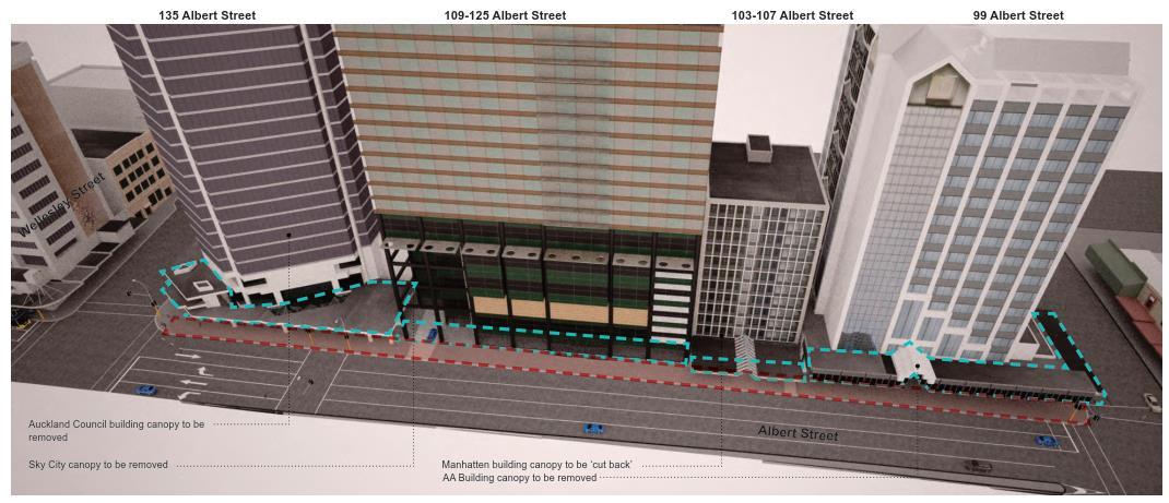
In 2017, City Rail Link Limited (CRLL) submitted an outline plan for canopy removal and utility relocation works within the Aotea Station area, along the western side of Albert Street between Victoria Street West and Wellesley Street West (Auckland Council ref. OPW60310921). This outline plan was accepted by Auckland Council without changes. Canopy removal works have now been completed
Additional utility relocation and canopy removal works are required beyond the footprint of the approved works. As such, the Link Alliance is seeking authorisation for works that are beyond the scope of OPW60310921.
This addendum updates the “Enabling Works Contract 2 Groundwater and Settlement Monitoring and Contingency Plan – Separable Portion 3 – Canopy Removal and Utilities Diversion”, dated 9 February 2018 and prepared by AECOM, (“the Approved GSMCP”) to address the additional utility works
This GSMCP addendum has been prepared in relation to the Stages 4 and 5 utility relocation works only The GSMCP will be revised in the future to include the Aotea Station main construction activities. A description of the Stage 4 and 5 works is provided in Section 2 of this GSMCP addendum.
This addendum must be read in conjunction with the Approved GSMCP.
The structure of the addendum is based on the Approved GSMCP.
1.2
Purpose of Groundwater and Settlement Monitoring and Contingency Plan
1.2.1.
Objectives of the GSMCP
The objectives of the GSMCP are, so far as reasonably practical, to:
• Prevent or minimise settlement damage that may affect the serviceability of buildings and services, and
• Provide appropriate measures to remediate or mitigate any adverse effects (including cumulative effects) as a result of the dewatering and excavation activities involved in the Stage 4 and 5 utility works
This GSMCP addendum addresses the matters specified in the conditions of Water Permit R/REG/2016/1892 (groundwater diversion and discharge) (“the Consent”).
1.2.2.
Performance Standards during Construction
No changes are proposed to Section 1.2.2 of the Approved GSMCP.
1.2.3. Predicted performance
The performance standards will be achieved through the specific design and construction methodology for the Stage 4 and 5 utility relocation works, and by the various monitoring, management and contingency measures described in Sections 5, 6, 7 and Appendix D of this GSMCP addendum
Provided that the recommendations outlined in Appendix D are implemented, any resulting ground surface settlements in combination with the effects from the main works should not result in the exceedance of the trigger levels outlined in the Consent for buildings in the Aotea Station works area
1.3 GSMCP Authors
This GSMCP addendum has been prepared by a senior qualified person (Geotechnical Professional), George Brink (PhD Engineering Geology).
George is an Engineering Geologist with Tonkin and Taylor. He has 10 years’ experience in the geotechnical characterisation and evaluation of soil and rock mass behaviour, as well as undertaking, managing, and reporting on geotechnical investigations for a number of international public and private sector clients.
This GSMCP addendum has been reviewed by a senior qualified person (Geotechnical Professional), Graeme Twose, NZCE (Civil), BE (Civil, Hons).
Graeme is a Senior Geotechnical Engineer with Tonkin and Taylor. He has over 20 years’ experience and has specialised in groundwater and settlement assessments for tunnels and deep excavationswith a particular focus on Auckland geology. His involvement in tunnelling and deep excavation projects spans investigation and feasibility stages, through to construction monitoring and contingency planning.
1.4 Consent Requirements
For completeness, Table 1-1 outlines the Regional Resource Consent conditions 82 to 129 that are specific to the GSMCP and Water Permit R/REG/2016/1892.
Pre-dewatering Services Survey
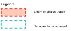
83 Within the 5mm settlement contours in Appendix 1 of the Consent, all excavations, dewatering systems, retaining structures and associated works (including backfilling) for the CRL construction must be designed, constructed and maintained to avoid any damage that exceeds the Serviceability limits of buildings, structures and services.
84 Beyond the 5mm settlement contours on the drawings in Appendix 1, the Consent Holder must ensure that the damage to masonry buildings due to the Project works, including excavations, dewatering systems, retaining structures and associated works (including backfilling), does not exceed the “negligible damage” category extent detailed in Table 1 of the Consent and has only negligible effects on piled buildings, structures and services.
90 The Consent Holder shall ensure that there is no long-term mounding due to damming of groundwater by the proposed rail infrastructure.
91 Prior to the Consent Holder submitting the GSMCP under Condition 97, the Consent Holder shall request that Council engage, at the cost of the Consent Holder, a suitably qualified independent specialist, agreed to by the Consent Holder, to fill the role of Independent Building Assessor (IBA). The Consent Holder shall acknowledge that the IBA can, at the expense of the Consent Holder, engage other independent specialists, but only in consultation with the Consent Holder.
92 The IBA required by Condition 91 shall report to the Manager on building damage matters and how these matters may be addressed by the Consent Holder.
93 Prior to the Commencement of Dewatering, and following the identification of potentially affected Services, the Consent Holder shall, in consultation with the relevant service provider, undertake a condition survey of all such Services. This condition does not apply to any Service where written evidence is provided to the Manager that the owner of that Service has confirmed they do not require a condition survey.
94 The monitoring of any settlement effects on those potentially affected Services shall be in accordance with Conditions 120 and 121.
95 In the event that the Services’ trigger levels are breached, the Consent Holder must carry out remedial actions in accordance with Conditions 125 and 128.
Groundwater and Settlement
Monitoring and Contingency Plan ("GSMCP")
Groundwater Monitoring
97
96 GSMCP requirements for certification by AC (timeframes and peer review)
98
99 Dewatering is not to commence until certification from the Manager is provided.
The GSMCP, required by Condition 97, shall include the requirements of the Consent including, but not limited to, the following:
a. an “as built” survey plan of all monitoring locations based on approximate positions located on the plans entitled:
• A02502731, Figure 39, Rev B dated May 2016 and ET Table 7.1 (Appendix 3); and
• The plans referred to in Appendix 1 and any further building-specific monitoring requirements determined from the detailed pre-construction building condition assessment.
b. full details (frequency and scope) of groundwater (including construction logs), ground surface, building, retaining wall, building façade, inclinometer monitoring programme and conditions surveys, and frequency and scope of visual inspections required by this consent
c. a bar chart, such as a Gantt chart, showing the timing and frequency of the condition surveys and monitoring required by this consent relative to the Commencement of Dewatering and the Completion of Dewatering;
d. details outlining the effects on groundwater
100
e. details of all alert and alarm triggers (including any necessary horizontal and vertical displacements), the frequency of monitoring and the criteria to cease monitoring for each ground, building and retaining wall deformation marks and inclinometers, extensometers. The alert and alarm triggers shall be an update of the provisional triggers provided on drawings CRL-SYW-RME-000-DRG-2640 Rev 4. dated 14 October 2016 and CRL-SYW-RME-000-DRG-2642 Rev 3. dated 11 October 2016
f. details of contingency measures to be implemented if alert or alarm triggers are exceeded including a Response Plan.
g. identification of any adjacent services susceptible to damage and details of any pre and post construction monitoring or inspection;
i. details of monitoring proposed to be undertaken to protect the issued groundwater diversion consents listed in the Consent Conditions against cumulative settlement effects;
j. identification of existing basements which could be subject to potential flooding from post-construction groundwater mounding; details of monitoring of long-term groundwater mounding effects; and details of groundwater drain construction to prevent groundwater mounding
k. the review of the proposed alarm and alert trigger levels in Appendix 2, approved by the IBA, following the pre-construction building condition surveys (required by Condition 109) that confirms they are set to ensure Serviceability Limits will be not be exceeded and whether the monitoring frequency is adequate, possibly requiring further site investigation work where sensitive structures are identified as part of Condition 112
101 The GSMCP may be varied, including frequency of monitoring, subject to the certification by Auckland Council, which is contingent on approval by the IBA.
102 Once certified, the GSMCP shall be implemented for the periods specified in the conditions of the Consent.
103 The Consent Holder shall advise the Manager, in writing, of the date of the proposed Commencement of Dewatering.
104 The Consent Holder shall install, maintain and replace if necessary, groundwater monitoring boreholes listed in Appendix 3 of this consent and shown on drawing A02502731, Figure 39, Rev B dated May 2016 (Appendix 3) and ET Table 7.1 (Appendix 3) of this consent, for the period required by the conditions of this consent
Section 1.2 and 4.2
Section 4.2
Section 1.2 and 4.2
Section 5
Appendix C
Section 3
Section 5
Section 6
Table 4-1
Section 5
Section 6
Section 7 and 8
Section 3.5, Section 6.4
Section 3.7
Section 5
Section 6.5
Section 1.2 and 8
Table 4-1
Section 4.2
Section 5
105 The Consent Holder shall measure and record groundwater levels at the monitoring boreholes specified above and at the frequency specified in Schedule B.
106 These records, reported in reduced level, shall be compiled and submitted to the Manager at monthly intervals.
107 The groundwater alert trigger level criteria is listed in Schedule C for the monitoring boreholes.
108 Where groundwater alert trigger levels are exceeded, as identified from monitoring data obtained pursuant to Condition 105, the Consent Holder shall undertake the actions set out in the certified GSMCP.
a. notify the Manager within 2 working days, advising the trigger exceedance, the risk of settlement causing damage to buildings, and details of the actions taken; and
b. send a copy of the material notified to Council to the relevant building owner
Prior to the commencement of dewatering/excavation, the Consent Holder shall employ an independent Senior Qualified Person to undertake a detailed pre-construction condition survey, of all relevant buildings to confirm their existing condition, subject to the approval of the property owner. The survey shall include, but not be limited to, the following:
a. any information about the type of foundations;
b. existing levels of damage considered to be of an aesthetic or superficial nature;
c. existing levels of damage considered to affect the serviceability of the building where visually apparent and without recourse to intrusive or destructive investigation;
109
d. a professional opinion as to whether observed damage may or may not be associated with actual structural damage;
e. susceptibility of the building or structure to further movement;
f. specific assessment of building damage with reference to the trigger levels identified in Appendix C of the Consent;
g. review of proposed alarm and alert trigger levels to confirm they are appropriately set and movement less than trigger levels set will not exacerbate damage, and whether the monitoring frequency and locations of monitoring points are adequate; and
h. photographic evidence of (b) and (c).
110 Where the Consent Holder is required to access property (including buildings or structures) owned by a third party to undertake monitoring, surveys or inspections and that access is declined or subject to what the Consent Holder considers to be unreasonable terms, the Consent Holder shall notify the Manager of that circumstance, and provide an alternative monitoring plan which includes the matters stated in Condition 100.
a. The Senior Qualified Person shall be identified in the CEMP (required by Condition 36);
111 Any condition survey undertaken in accordance with Condition 109, or any other condition surveys undertaken by the Consent Holder, shall be undertaken as follows:
b. Contact owners of those buildings and structures where a condition survey is to be undertaken to confirm the timing and methodology for undertaking a preconstruction condition survey;
c. Record all contact, correspondence and communication with owners and this shall be available on request for the Council;
d. Provide the building condition survey or structure condition survey report to the relevant property owner and the Council within 15 working days of the survey being undertaken;
e. The Consent Holder shall undertake a visual inspection during construction if requested by the building or structure owner where a pre-construction condition survey has been undertaken and monitoring data and observations note any changes from the pre-construction condition survey report.
f. Develop a system of monitoring the condition of existing buildings or structures which is commensurate with the type of the existing building or structure and the proximity of the project works in order to assess whether or not construction activities are compromising the structural integrity of the building or structure.
112 Should the pre-construction building condition survey and assessment highlight greater sensitivity of buildings than envisaged by the application, and should this increased sensitivity mean that the Serviceability Limit for the building may be exceeded, then the Consent Holder shall, at its cost, implement additional measures that may include modifications to the design of the retention systems or further geotechnical investigation).
113 The Consent Holder shall carry out a visual inspection of the surrounding ground and external building facades of the listed buildings in Appendix 2 adjacent to the tunnel/trench and station alignment to monitor for any deterioration or movement of any pre-existing cracks at a frequency to be specified in the GSMCP.
114 Keep a record of the time, date and any observations for each inspection. This record is to be maintained and submitted to Auckland Council in accordance with Condition 128.
Section 6.2
115
No earlier than six months after Completion of Dewatering and within six months of Completion of Construction, a detailed condition survey all previously surveyed buildings, structures and water, stormwater and wastewater services, shall be prepared by a suitably qualified engineering professional. This condition survey report shall address all matters reviewed in the pre-dewatering condition survey. It shall also identify any new damage (if any) that has occurred since the pre-dewatering condition survey was undertaken and include a determination of the cause of any such damage and steps to repair it as provided for in Condition 125.
The requirements of this condition need not be fulfilled for any particular building where the Consent Holder can provide written evidence to the Manager that the current owner of that building has advised they do not require such a condition survey.
116 At the reasonable request of the Manager, the Consent Holder shall, without delay, undertake an additional condition survey of any building within the area defined by the groundwater monitoring, deformation monitoring and modelling undertaken pursuant to the conditions of this consent potentially affected by excavation, for the purpose of checking for damage and follow up with a report of damage to that building.
Section 6.2
Table 4-1
Section 7
Building Inspection
Section 6.2
Ground Surface and Building Monitoring
117 Subject to Condition 125, the requirement for any such condition survey will cease 6 months after the Completion of Construction, unless the requirements of Condition 115 have not been met and subject to a consistent pattern of deformation records having been obtained in this period in which no evidence of adverse effects is apparent.
119 Establishment and maintenance of a settlement monitoring network (ground settlement and building movement monitoring marks) to detect any deformation: Section 6
a. The minimum scope of settlement monitoring
b. Subject to the owners’ approval, at least two sets of building movement monitoring marks shall be located on each building
c. The final location and number of building movement monitoring marks shall take into account the building type and size, accessibility to survey the marks and risk of damage from ground settlement and the effects of differential settlement from the predicted settlement values.
120 Monitoring frequency and duration, and baseline monitoring records.
121 Post construction monitoring plan for areas where groundwater drainage is proposed and consolidation settlement risks are identified that could cause building damage
Retaining Wall Monitoring
Contingency
122 The Consent Holder shall install retaining wall deflection pins as near to the top of the wall as practicable, with inclinometers installed either in a retaining pile or immediately behind one and extending to the base of the retaining pile for the monitoring of wall deflection
123 Monitoring of the retaining wall pins and inclinometers shall be undertaken and recorded in accordance with Schedule E in the Consent, unless otherwise specified and agreed in the GSMCP.
124 In response to the event of any Alert or Alarm trigger level exceedance (ground surface, building and/or groundwater levels) the following shall occur:
a. Notify AC and the IBA within 24 hours;
b & c. If alert values are exceeded, a senior qualified person shall assess the works constructed up to that time and provide a report to AC within one week. Measures (if any) to be implemented are to be as identified in the GSMCP.
d. If alarm values are exceeded, the process outlined in Condition 124b shall be undertaken. The report shall also include any recommendations for remedial actions if required in order to complete construction. These recommendations shall be implemented prior to recommencing works.
e. Where alarm levels are exceeded, remedial recommendations and actions of the IBA may also be considered. This shall be implemented, unless the building owner(s) request in writing that the construction works are to be completed in accordance with the report prepared under Condition 124d.
125 The required response and repairs should any damage to buildings, structures or services be caused wholly or in part by the exercising of the Consent
126 AC shall be advised in writing within ten working days of Completion of Dewatering.
Reporting
127 AC shall be advised in writing within ten working days of Completion of Construction.
128 Compilation, comparison and submission frequency to AC of all data collected during the monitoring programme.
Section 6.3
Section 7
Section 7
Section 4
2. Project Description
2.1 Aotea Stage 4 and 5 Utility Relocation Works
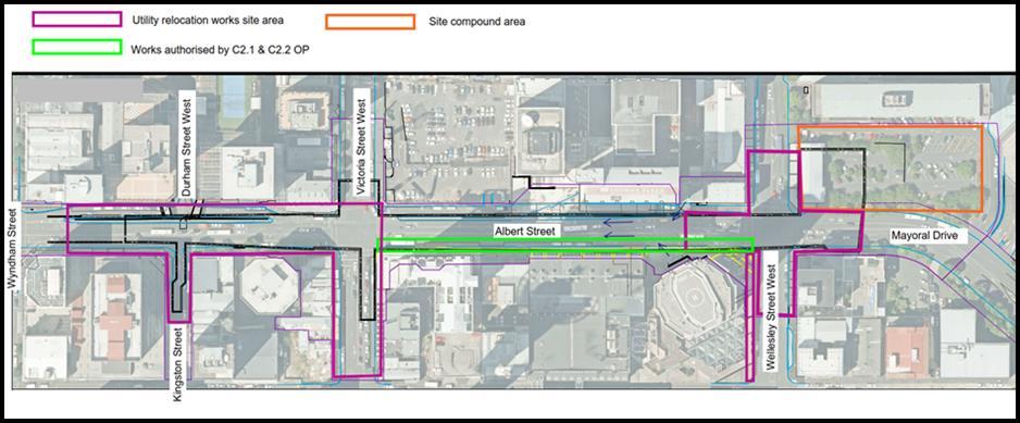
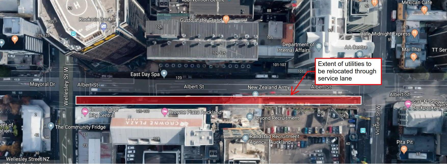
The project site applicable to this GSMCP addendum is located within Albert Street and the adjoining streets, between Wyndham Street and Mayoral Drive. The Stage 4 and 5 utility relocation works, canopy removal works and Construction Support Area establishment (herein referred to as the ‘Stage 4 and 5 works’) involves the following main activities:
• Utility relocation activities via trenching;
• Utility relocation activities via micro-tunnelling within Victoria Street West;
• Closure of the Albert Street / Wellesley Street intersection to undertake east-west and north-south trenching works for utility relocation;
• Closure of the southern slip lane from Durham Street to Albert Street for approximately 4 to 6 weeks to allow for utility relocation;
• Closure of Kingston Street for approximately 4 to 6 weeks to allow for utility relocation;
• Directional drilling along Wellesley Street between Albert Street and Federal Street, and;
• Establishment of a construction compound to support the subsequent main station construction works.
The Stage 4 and 5 works will be undertaken along parts of Albert Street, Kingston Street, Victoria Street West, Wellesley Street and Mayoral Drive. In addition, a construction compound (herein referred to as the ‘Construction Support Area’ (CSA)) required to support the main works is to be established within the outdoor car park area to the west of Bledisloe House. The site adjoins the project area of the canopy and utility works authorised by OPW60310921
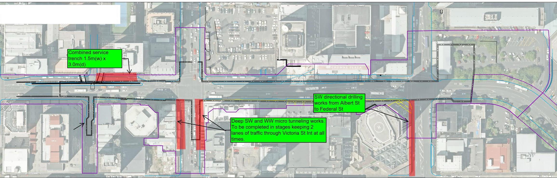
The area of the Stage 4 and 5 works is illustrated in Figure 2-1 below.
The majority of the utility relocation works will be carried out in shallow (2m or less) unsupported trenches The Stage 4 and 5 works relevant to this GSCMP addendum include:
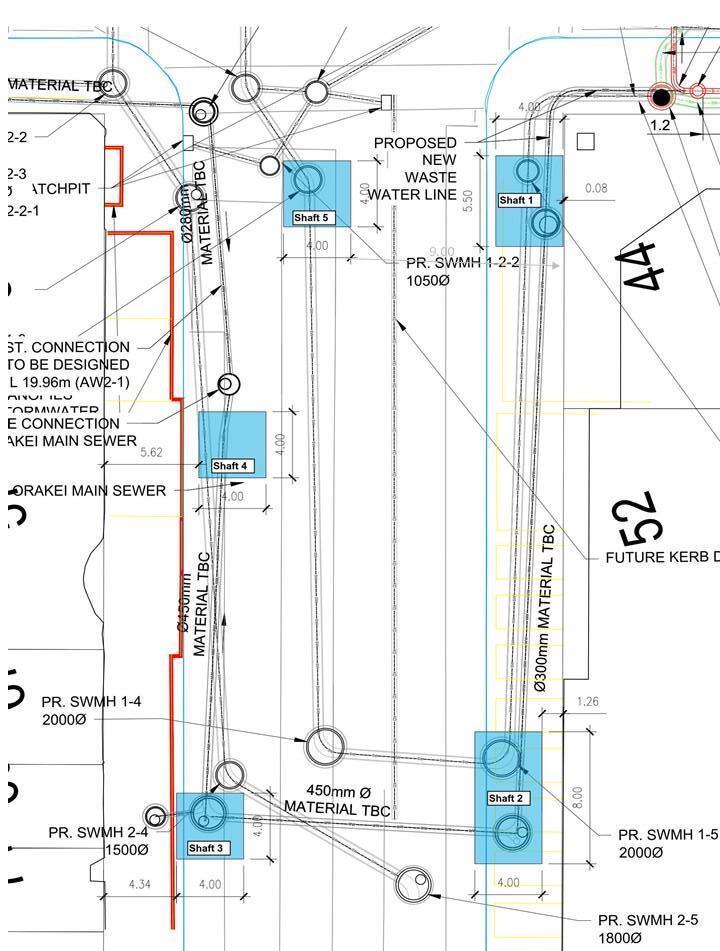
• Micro-tunnelling and shaft excavations for deeper services relocation along Victoria Street West. Deeper stormwater and wastewater service relocation along Victoria Street West will require the provision of five shafts (Shafts 2 and 3 8m in depth, Shafts 1, 4 and 5 to 4m in
Figure 2-1: Stages 4 and 5 enabling works layout
depth, Appendix D) to allow for micro-tunnelling using a Micro Tunnel Boring Machine (MTBM). The current proposed construction methodology assumes the shafts will be supported using sheet piles, but the details and design of which needs to be confirmed. The diameter of the new stormwater and wastewater lines are 630mm and 450mm respectively. No information regarding the dimensions of the proposed micro-tunnel works or tunnelling methodology is currently available;
• Directional drilling and shaft excavations for deeper services relocation from Albert Street to Federal Street. These drilling works will be undertaken from the northwest corner of Albert / Wellesley Street intersection; involving a 5m deep launch and receival shaft at either end of the works and directional drilled bore between No information is currently available regarding the final positions of the proposed directional drilling shafts or the directional bore diameter;
• Combined service trenching along southern slip lane from Durham Street to Albert Street and service lane between Victoria Street and Wellesley Street. This trench will not exceed 1.5m in width and 3m in depth and will be excavated using either a hydrovac or standard excavator
Details of these activities are provided in the Construction Environmental Management Plan (CEMP) addendum for the Stage 4 and 5 works
2.2
Construction Methodology
The utility relocation and CSA establishment works will be divided into stages The detailed methodology and staging plans for utility relocation proposed during the Stage 4 and 5 works is set out in the CEMP addendum.
3. Existing Environment
3.1 Land Use and Topography
The area surrounding the Stage 4 and 5 utility works is a dense urban environment with a built form comprised of medium to high rise buildings. Common land uses include commercial offices and services, residential apartments, retail, civic, hospitality, hotel accommodation and car parking. Buildings adjoin much of the project site boundary (road corridor) and there are numerous underground utilities in the vicinity.
The Albert Street area has a gentle sloping topography, dropping from south to north towards the coast, with Albert Street located on the flank of the Queen Street valley and near the ridgeline of Hobson Street. Intersecting streets strike east-west down the valley slopes to Queen Street (e.g. Swanson, Victoria and Wellesley Streets) and are steep relative to Albert Street.
3.2 Geology
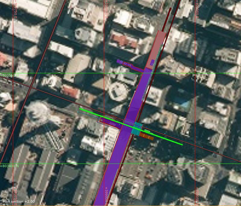
The detailed CRL Project ground conditions are described in detail in the Link Alliance Geotechnical Baseline Report (AGBR)1. A representative geological cross-section along Victoria Street exported from the 3-D geological model is attached as Appendix A to this GSCMP addendum
In summary, the general vertical stratigraphic sequence along Victoria Street comprises the following:
• Fill, asphalt or concrete pavement forms the ground surface and is underlain by granular base coarse, sub-base and/or variable fill materials, generally varying in thickness between 2 – 2.5 m along Victoria Street;
• Alluvium deposits of Pleistocene age Tauranga Group Alluvium infills the head of a paleotributary gully, running towards the Queen Street valley to the east. These unconsolidated deposits comprise clay, silt, sand and gravel, and unconformably overlie the ECBF. The thickness varies, from being absent near the Symonds Street ridge in the west up to a thickness of 9 m in the area of the main station footprint near Albert Street;
• The thickness of the residual ECBF varies due to the weathering and erosion along the gully prior to being infilled with alluvium. The residual ECBF directly underlies the fill (where no alluvium deposits are present), ranging in thickness from 11 m (west of Albert Street) and 14 m (east of Albert Street).
• The thicknesses of the weathered ECBF is relatively consistent along Victoria Street (approximately 3 m thick), before grading into unweathered ECBF at elevations between 0 and 10 m RL.
3.3 Hydrogeology
Historically the Aotea Station area was within a surface water catchment that was delineated by the ridgeline water shed located upslope and to the west of the location of the station. Surface water flows were channelled through gullies and preferential pathways, running east-west and downslope towards the former Waihorotiu Stream, or Queen Street River.
The basic groundwater model assumes the following:
Perched Groundwater System - Water levels in the Tauranga Group and residual ECBF in the region surrounding Victoria Street have been recorded at approximately 8.5 m bGL Available historical monitoring data for Borehole BH206 A (located in the immediate vicinity of the proposed Stage 4 and 5 works) indicate the perched water levels to be marginally shallower at 16 m RL (approximately 10 m BGL). Significant water level responses occur in the perched units after rainfall events, with about 0.4 m increase in water level following a rainfall event. Seasonal groundwater level variations are likely to be about 2.0m.
The perched water tables are associated with more permeable lenses and are not laterally continuous, and this restricts the volumes of water contained in these units and the lateral migration of water in comparison to the regional aquifer below.
Regional Groundwater System - The discontinuous series of perched groundwater zones overly the more continuous regional groundwater table within the ECBF (at approximately 5 to 10 m RL), which falls to the north (towards the harbour) and to the east. Seasonal groundwater level variations are likely to be less pronounced than for the upper perched units, with water level records indicating a delayed response to rainfall.
The hydrogeological conditions across the CRL Project are described in detail in the PDP Groundwater Technical Report 2
3.4 Existing Buildings and Structures
Buildings encountered along and adjacent to the area of works range from modern multi-storey piled structures to low-rise heritage brick masonry buildings on shallow foundations, and that are used for a mix of residential, entertainment, commercial and retail.
The most critical buildings within close proximity to the project were identified during the consenting process and those buildings particularly relevant to the Aotea Stage 4 and 5 utility works are identified in Table 3-1
Table 3-1 List of buildings in Aotea Stages 4 and 5 works area
3.5 Existing Basements
Table 3-2 identifies basements located in close proximity to the Stage 4 and 5 works, based on the available property records
2 PDP, (2016). Auckland City Rail Link Aotea Station to North Auckland Line Construction and CRL Operation: Groundwater Technical Report. Prepared for Aurecon on behalf of Auckland Transport, dated May 2016.
Table 3-2
of basements near Aotea Stages 4 and 5 works
3.6 Existing Utilities
There are a number of utilities which currently run close to the proposed shaft excavations for the Stage 4 and 5 works:
• Stormwater (reinforced, and potentially unreinforced, concrete; polyvinyl chloride (PVC), earthenware and asbestos cement).
• Wastewater (brick, earthenware, asbestos cement, and cement-lined cast iron).
• Potable Water (cement-lined cast iron, ductile iron, cast iron, asbestos cement, polyethylene (PE), and concrete lined steel).
• Electricity (direct buried cables, and cables in PE/PVC ducts).
• Telecommunications (direct buried cables, cables in PVC/PE/cast iron ducts, and fibre optic in PVC/PE/cast iron ducts).
Dry services and shallow stormwater and wastewater within the footpath and carriageway will be relocated as part of the works along Victoria Street.
The Orakei Main Sewer (OMS) runs at a very flat grade along Victoria Street, beneath the proposed CRL project tunnel (northern end of station box). The OMS will not be affected by the comparatively shallow Stage 4 and 5 works in this area.
3.7 Issued Groundwater Diversion Consents
Condition 100 (i) of the Consent requires the GSMCP to include details of the monitoring proposed to be undertaken to protect the issued groundwater diversion consents listed in the Consent against cumulative settlement effects.
Considering their discontinuous nature and modified near-surface ground conditions in the region of the CBD, the presence of perched groundwater layers is difficult to predict with reliability. Based on the existing regional historical monitoring data, the Stage 4 and 5 works are not expected to intersect perched groundwater layers. The perched water tables are associated with more permeable lenses and are not laterally continuous, and this restricts the volumes of water contained in these units and the lateral migration of water. Should the works intersect a perched water layer, any effects are expected to be localised.
The regional groundwater table will not be intersected by the proposed Stage 4 and 5 works. None of the existing groundwater take consents identified in the A2N Resource Consent will be affected by the Stages 4 and 5 works
4. Overview of Monitoring and Reporting Requirements
This section provides an overview of the monitoring and reporting required for the Aotea Stage 4 and 5 utility relocation works in accordance with the Consent.
4.1 Construction Stages
Monitoring shall be completed, and records compiled and submitted to Auckland Council by those responsible during the stages and frequencies outlined in Figure 4-1 and Table 4-1 hereafter.
Pre-construction Monitoring
•This monitoring phase will provide baseline data against which effects resulting from the construction works can be assessed. The outcomes will form part of the input for the construction phase assessments.
During Construction Monitoring
Post-Construction Monitoring
•Monitoring during the bulk excavation phase will be used to verify the design analyses, by comparing the actual measurements with those estimated. The monitoring data will be used to reassess the building damage classifications at critical locations.
•If these reassessments indicate that the damage classifications have increased significantly then additional analyses, increased monitoring or other actions may be required. Mitigation options, discussed in Section 7 of this GSMCP, may also be required to be implemented.
•Where specified in the Consent, monitoring will occur until the various stages of works are completed (excavation, dewatering and construction), and shall continue as required until stable measurements are demonstrated, and written approval is provided by the Council.
Figure 4-1 Summary of Construction Monitoring Stages
Table 4-1: Summary of Monitoring Requirements relevant to Water Permit R/REG/2016/1892
Monitoring
Baseline
Groundwater Monitoring
Excavation/ dewatering
PostConstruction
Dewatering
Weekly for at least 3 months before commencing dewatering and those boreholes listed in Appendix 3 of the Consent.
Three times a week for all monitoring boreholes until completion of dewatering.
Daily, should the Groundwater Alert Trigger level be exceeded.
Monitoring shall continue until either six months after the completion of dewatering, or until such time following the completion of dewatering that monitoring of settlement and building monitoring marks has ceased under Condition 120.
Baseline
Building Condition Surveys (BCS)
Excavation/ dewatering
A detailed pre-construction condition survey is to be carried out of all buildings identified in Appendix 2 of the Consent and relevant to this GSMCP (subject to approval of the property owner).
A visual inspection will be undertaken during construction if requested by the building or structure owner where a preconstruction condition survey has been undertaken and visual observations or monitoring data indicates changes from the pre-construction condition.
Visual inspections of the surrounding ground and external facades of buildings identified in this GSMCP will be carried out quarterly (3 months) from the commencement of excavation / dewatering, or within one week of the completion of works for shorter duration activities. This is to monitor for any change in condition from pre-construction conditions.
PostConstruction
Dewatering/ excavation
A post-construction condition survey shall be carried out no earlier than 6 months after completion of dewatering/excavation and within 6 months of completion of construction for any building that had a pre-construction survey.
10mm
Monthly for routine monitoring.
Within 2 working days of any alert trigger level exceedances
Within 15 working days to the relevant property owner. A copy of each report shall be provided to the Council
A record is to be maintained of the time, date and any observations for each inspection. This record is to be maintained and submitted to AC at two monthly intervals or upon reasonable request from the Council Representative.
Ground Surface and Building Monitoring
Baseline
Excavation/ dewatering
Each ground settlement and building movement monitoring mark shall be surveyed and recorded at least three times prior to the commencement of excavation / dewatering to establish a baseline elevation.
Depending on the stage of construction:
- Monthly, at each ground settlement and building monitoring mark,
- Daily for two weeks and weekly thereafter for all ground and building settlement markers within 50m of excavations during excavation until such time following the completion of excavation that stable measurements are demonstrated.
PostConstruction Dewatering/ excavation
Monthly for six months, or until stable measurements are demonstrated and written approval is provided by Council for certification.
Horizontal and vertical accuracy of at least ±2 mm, or as otherwise achieved by precise levelling during baseline phase.
To be compiled and submitted to the Council prior to the commencement of excavation.
A record is to be maintained of the time, date and any observations for each survey, and submitted to the Council at two monthly intervals.
4.2 Notification and GSMCP Certification
No change is required to this section of the Approved GSMCP. It is noted any reference to ‘Connectus’ should be changed to the “Link Alliance’ in order to reflect the contractor undertaking the works.
4.3 Data Collection and Reporting Requirements
All data collected will be compiled, compared with the relevant trigger levels (summarised in Section 0) and submitted to Auckland Council at two monthly intervals, unless otherwise specified or requested in the Consent
4.4 Independent Building Assessor Reporting Requirements
No change is required to this section of the Approved GSMCP.
4.5 Roles and Responsibilities
The relevant Roles and Responsibilities for the Stage 4 and 5 works are outlined in Table 4-2 hereafter.
Table 4-2: Roles and responsibilities
Role
Consent Holder (CRLL)
Project Director (Matt Sinclair of the Link Alliance)
Environment and Sustainability Manager (Sarah Sutherland of the Link Alliance)
Role Responsibility
Requiring Authority, Consent Holder and Project Manager (the Link Alliance)
Overall responsibility for project compliance and performance in relation to environment, quality assurance and incident management
Reviewing and reporting on environmental performance.
Inspection of works to assess compliance with the GSMCP including monitoring.
Inspecting, auditing and checking of environmental management practices and procedures.
On-site compliance with consent conditions and other requirements and tracking compliance information.
Reporting to CRLL changes to construction techniques or changes in environmental conditions which require alterations to existing consents or new resource consents.
Preparing, reviewing and updating the CEMP and relevant sub-plans (including GSMCP).
Facilitating and overseeing environmental monitoring, including reporting to CRLL and Auckland Council
Updating and maintaining the environmental portion of the Project Risk Register.
Training of all staff including subcontractors.
Instrumentation and Monitoring Manager
Reviewing the data and correlating the monitoring observations with construction activities and design assumptions.
Communicating trends and observations to the Project Director, relevant members of the construction team, and CRLL.
Responding to Alert and Alarm triggers.
Managing contingency measures and responses in the event that an Alarm level is exceeded.
Design Lead –Groundwater and Settlement Effects
Independent Building Assessor (IBA)
Prepare, review and update of GSMCP
Additional inputs will be provided on an as-requested basis, with assistance from other Technical Specialists as required.
Reviewing the GSMCP and any reports associated with alarm triggers.
As an advocate for local stakeholders, the IBA will also receive and review monitoring data and on behalf of Auckland Council to track progress and building damage and building effects.
5. Groundwater Monitoring Plan
The proposed early works will extend to a maximum depth of 8 m bGL (micro-tunnelling shafts along Victoria Street) and will not intersect the regional groundwater regime (approximately 10 m below the invert of the excavation at this location).
Evidence from the C2 works monitoring results (immediately adjacent to the Aotea Station area) indicate no correlation between dewatering of the perched groundwater and recorded ground surface settlement. The perched water tables are not laterally continuous and would have been extensively modified from its natural condition by the surrounding building development, filling and existing utilities acting as drains and connections between lenses
No groundwater monitoring plan is included as part of this GSMCP for the Stages 4 and 5 early works.
6. Settlement Monitoring Plan
6.1
Introduction
The settlement monitoring actions, instrumentation and trigger levels described in this section are based on the outcome of the estimate of settlement effects for the enabling works construction stage (attached as Appendix D to this GSMCP addendum), and in accordance with the relevant conditions of the Consent.
This section outlines the building condition and settlement monitoring program the Link Alliance will implement to:
• Verify design assumptions;
• Confirm the construction induced surface settlements; and
• Provide warning that mitigation is required to minimise or rectify potential adverse effects of settlement on structures.
6.2 Building Condition Surveys
6.2.1.
Building Condition Surveys and Visual Inspections
The buildings for which BCS are required as part of the Aotea Stage 4 and 5 works are summarised in Table 3-1 of this GSMCP addendum, and form part of the list of structures listed in Appendix 2 of the Consent.
BCS are required to be carried out for all the listed structures as part of the CRL project, including those buildings in the Aotea Station area. The BCS for the structures above will be completed before and after the enabling works activities to identify and monitor effects to buildings in accordance with Consent Conditions 109 - 117.
The following general requirements apply to all BCS and visual inspections during each stage of the Project:
• The BCS shall be undertaken by an independent Senior Qualified Person
• All contact, correspondence and communication with building owners will be recorded, with documents available on request.
• The BCS or structure condition survey reports shall be provided by the Link Alliance to the relevant property owner within 15 working days of any survey being undertaken. A copy of each report shall also be provided to CRLL and Auckland Council.
• Damage to buildings identified during BCS and visual inspections resulting from the enabling works activities requires action as outlined in Section 7 of this GSMCP.
6.2.2. Pre-Construction Surveys
Individual pre-construction BCS of all structures listed in Table 3-1 of this GSMCP will be undertaken to establish a baseline building condition against which any subsequent surveys can be compared. The owners of the buildings and structures will be contacted in advance to confirm the timing and methodology for the pre-construction survey. All contact, correspondence and communication with the owners will be recorded and available on request for Auckland Council
Where the pre-construction building condition survey and assessment highlight greater sensitivity of buildings than envisaged by the application, and should this increased sensitivity mean that the Serviceability Limit for the building may be exceeded, then the Link Alliance shall implement additional measures as discussed in Section 7.
In the event that access is declined or subject to what the Consent Holder considers to be unreasonable terms, the Consent Holder shall notify the Manager of that circumstance, and provide an alternative monitoring plan which includes the matters stated in Condition 100 of the Consent.
6.2.3. During-Construction Surveys
Visual inspection of ground and buildings adjacent to the Stage 4 and 5 works shall be carried out according to consent conditions as follows:
• The Link Alliance will undertake a visual inspection during construction if requested by the building or structure owner where a pre-construction condition survey has been undertaken. Where a condition survey has been undertaken by the building or structure owner, the Consent Holder shall continue to undertake quarterly (3 months) visual inspections until the completion of dewatering/excavation of the project; and
• The Link Alliance will carry out a visual inspection of the surrounding ground and external building facades of the buildings identified in Section 3.4 to monitor any deterioration or further cracking of any pre-existing cracks. This will be carried out at least quarterly from the commencement of any dewatering / excavation until completion of excavation, or (in the event of shorter duration activities) within 1 week of completion of the works.
A record will be maintained of the time, date and any observations for each inspection. This record will be submitted to Auckland Council
6.2.4. Post-Construction Surveys
Post-construction BCS will be completed after the completion of the Aotea Station main works (which will follow the early works outlined in this GSMCP). No earlier than 6 months after the completion of the Aotea Station main works dewatering / excavation, and within 6 months of completion of the Aotea Station main works construction, post-construction BCS will be carried out on all buildings where a building condition survey was undertaken prior and during the construction phase. The survey report will include an assessment of the cause of any damage identified. If a
complaint is made around building damage following completion of the Stages 4 and 5 early works, a post-early works construction BCS will be carried out for that particular building.
Additional BCS and reporting up to 6 months’ post-construction on any building within the area potentially affected by the excavation may be completed at the request of Auckland Council. The requirements for any such survey will cease six months after the completion of construction, and subject to a consistent pattern of deformation records in which no evidence of adverse effects is apparent.
The post-construction building surveys may not be required in the event that the building owner agrees that the building survey is not required, and written evidence is provided to Auckland Council.
6.3 Monitoring
6.3.1. Ground and Building Monitoring Locations
Ground and building survey monitoring marks will be installed along the areas likely to be affected by the Stage 4 and 5 works, and as shown in the drawings attached as Appendix C. The locations and spacing of these positions have been selected to avoid future (main works) duplication of monitoring points. Where the effects from the utility relocation works are likely to extend beyond the monitoring area proposed for the main works, the proposed monitoring points have been extended to include the area of utility works.
• Building Monitoring Marks: A minimum of two sets of three pins, will be installed at three different levels along the building face and on each building identified and listed in Section 3.4 of this GSMCP addendum. Monitoring marks are proposed to be installed at 10m centreto-centre intervals, with at least one set installed on the side of the structure closest to the excavation.
• Ground Monitoring Marks: Monitoring marks will be installed at 2.5m centre-to-centre spacing along the first 10m of the building perimeter walls that lead away from the edge of the excavation, increasing to 5m spacing after that. At least one monitoring point is required at the rear of the building footprint. The spacing of ground monitoring points can be reduced to 10m spacing past the building footprint and up to the 5mm settlement contour line developed for the main works in this area.
The location and number of monitoring marks takes into account the building type/size, accessibility and risk of damage from ground settlement.
Building Movement Monitoring Markers shall be located on each building identified subject to owners’ approval. This will allow the actual building movement to be monitored and compared with the estimated potential effects. It is proposed, and subject to owners’ approval, that these monitoring points be left in place after the required monitoring period for the enabling works has ended and in anticipation of the main works.
Monitoring will be completed before construction commences, during construction and following completion to confirm the effects of these works (as summarised in Table 4-1)
6.3.2.
Pre-construction Settlement Monitoring
The Link Alliance will survey and record each ground settlement and building movement monitoring mark at least three times prior to the commencement of excavation to establish a baseline set of readings. Monitoring data from C2 indicate seasonal shrink-swell movements in the order of up to +5mm to -5mm (measured from an average level over a 12-month monitoring cycle) could be expected.
The recorded baseline monitoring readings will take into account this historic data trends, and the effects considered in the adopted trigger levels for the construction/post-construction monitoring periods.
6.3.3. During Construction Settlement Monitoring
Monitoring during construction will comprise surveys of monitoring marks. The ongoing frequency of monitoring the survey marks will vary depending on the monitoring station position:
• At each ground settlement and building monitoring mark, within 50 m of an excavation during excavation / dewatering on a daily basis for two weeks and weekly thereafter; and
• At all other ground settlement and building monitoring mark locations on a monthly basis.
6.3.4.
Post-Construction Settlement Monitoring
Monitoring of the survey marks will continue monthly for six months, or until stable measurements are demonstrated and written approval is provided by the Council.
6.4 Utilities and Infrastructure
Pre-construction
The Link Alliance has identified the utilities potentially affected by the early works and have consulted with the relevant utility owners to determine the extent of pre-construction surveys required.
CCTV surveys will be completed on the existing stormwater and wastewater networks in the areas adjacent to the early works excavations. No need for other pre-construction surveys was identified, as the early works activities are primarily concerned with relocating the utilities in question.
During Construction Settlement Monitoring
The monitoring of any settlement effects on adjacent utilities will be carried out utilising the ground settlement markers utilised for ground settlement monitoring as outlined in Section 6.3.1.
Post-Construction
Settlement Monitoring
A post-construction condition survey will be carried out no earlier than 6 months after completion of dewatering/excavation of the Aotea Station main works, and within 6 months of completion of construction for any building that had a pre-construction survey. This will serve to confirm that the immediately adjacent utilities identified in the pre-construction survey have not been damaged.
The post-completion survey is to be provided in writing to Auckland Council and will include a determination of the cause of damage identified (if any) since the pre-construction survey, and a description of the steps taken to repair any damage.
6.5 Settlement Trigger Levels
The trigger levels for the respective monitoring actions outlined above are presented in Table B-1 and B-2, Appendix B.
The magnitude of vertical movements due to excavation stress relief depends on the dimensions of the excavation and ground conditions, construction methodology and level of support stiffness. The enabling works construction designs have yet to be finalised at the time of writing. A conceptual high-stiffness design was therefore considered in the completion of this GSMCP in order to assess the potential effects from these works on adjacent structures (Appendix D)
The settlement effects from the proposed Stages 4 and 5 works on adjacent buildings are expected to be negligible.
The pre-construction BCS along the area of the proposed works are being completed at the time of writing. The GSMCP for the Aotea Station Stages 4 and 5 early works will adopt the trigger levels outlined in the existing Aotea to NAL Regional Resource Consent drawings CRL-SYM-RME-000-DRG2640 Rev 4 and CRL-SYM-RME-000-DRG-2642 Rev 3, as discussed and agreed with the IBA (email correspondence dated 5 November 2019, and accompanying the GSMCP).
7. Response, Mitigation and Contingency Plan
7.1 Introduction
This section presents the triggered action response plan required where exceedances of trigger levels have been identified during monitoring, as outlined in Sections 5 and 6 of this GSMCP.
7.2 Response to Alerts
7.2.1. Groundwater Alerts
No groundwater alerts have been specified in this GSMCP addendum for the Stage 4 and 5 utility relocation works in the Aotea Station area (for the reasons set out in Section 5 of the addendum)
7.2.2. Settlement Alerts
In the event that settlement exceeds the identified Alert trigger levels during construction works, the following procedures will be undertaken:
• Auckland Council and the IBA will be notified within 24 hours.
• A Senior Qualified Person engaged by the Link Alliance or the Alliance’s contractor shall reassess the works constructed up to that time to confirm the works progress against design predictions, any additional measures to restrain further increases in movement, the possible ensuing effects will exceed serviceability limits.
• A written report will be prepared by the Senior Qualified Person responsible for overview of the monitoring and provided to the Council within one week of alert level exceedance. The report will provide analyses of all monitoring data relating to the exceedance of any of the trigger levels and any actions taken.
7.3 Response to Alarms
In the event that settlement exceeds the identified Alarm trigger levels during construction works, the following procedures will be undertaken:
• Follow the process set out in Section 7.2
• Commission and submit a written report, prepared by the Senior Qualified Person engaged by the Link Alliance to the Manager, within one week of alarm level exceedance This will provide analyses of all monitoring data, relating to the exceedance of any of the trigger levels and any recommendations for remedial actions, if required, in order to avoid damage that will affect building Serviceability, and which may also allow Completion of Construction.
• Implementation of recommendations.
The IBA may also recommend actions to prevent damage to building serviceability, which may include stopping the works if that is in the best interests of preventing building serviceability damage. These recommended actions will be implemented, unless the building owner(s) request in writing that the construction works are to be completed in accordance with the report prepared by the Senior Qualified Person
7.4 Response to Building or Utility Damage
In the event that damage to buildings, structures and / or services is reported during the enabling works or determined from a building condition survey or inspection the following will occur:
• The Link Alliance will notify the Manager and building/asset owner as soon as practically possible;
• Engage a Senior Qualified Person to prepare a report as soon as practical, describing the damage and identifying methods to avoid and mitigate the potential for Serviceability damage and to remedy any damage caused wholly or in part by the exercising of this consent; and provide a copy of the report to the IBA, Manager and the building/asset owner;
• The reported damage will be compared with the pre-construction building condition survey to determine if the damage is:
• Pre-existing,
• New, or
• Pre-existing, but exacerbated.
• The construction history in the vicinity of the building will be reviewed, along with the recorded settlement history, to determine if the damage can be reasonably attributed to the construction works.
• If the damage can be reasonably attributed to the enabling works, repairs will be undertaken as soon as practicable unless written approval for this damage is provided from the owners stating alternative arrangements (in accordance with Consent condition 125). The timing and nature of the repairs will depend on the owner’s requirements, stage of construction and degree of damage.
7.5 Mitigation Options
In the event that differential settlement or total settlement exceeds the identified Alert or Alarm trigger level during construction works, or ground conditions differ significantly from the design assumptions then the mitigation options include:
• Additional specific structural and geotechnical evaluations;
• Strengthen and / or stiffen ground support;
• Installation of additional instrumentation;
• Further structural assessment of an affected building.
The most appropriate contingency measure will be implemented to mitigate the actual or anticipated adverse effects of the triggering event.
8. Monitoring and Contingency
Plan Review
This section outlines how the GSMCP will be reviewed including the mitigation and contingency procedures to make sure they are still applicable to the activities carried out.
8.1 General Review of the GSMCP
The GSMCP will be updated, with the necessary certification by Auckland Council, throughout the course of the works to reflect material changes associated with changes to construction methods or site conditions. Auckland Council certification will be required for any relevant revisions of a material nature to the GSMCP.
This GSMCP addendum only addresses the proposed Stage 4 and 5 utility relocation works. The GSMCP will be updated in future, taking into account the effects of the main station development and all relevant groundwater monitoring and reporting requirements.
8.2 Review of Monitoring and Contingency Requirements
The Consent allows for variation to the monitoring and reporting requirements, and performance standards (subject to certification by Auckland Council) in order to take account of information, including the results of previous monitoring and changed environmental knowledge, on:
• Ground conditions;
• Aquifer parameters;
• Groundwater levels; and
• Ground surface deformation.
Furthermore, the conditions of Consent allow for specific review and updates to the following:
• Review of the settlement alarm / alert / stop trigger levels: The trigger levels as provided in the Consent and Section 0 of the GSMCP may be revised following the BCS, and an assessment to confirm these are appropriately set and monitoring frequency is adequate.
• Instrumentation: The specification of instruments, location and numbers of instruments may be modified as a result of the following:
• Additional geotechnical investigation and ground characterisation;
• Specification of instruments and monitoring tools;
• Findings of the BCS;
• Detailed design of the temporary trench support system;
• Modelling of the anticipated ground movement and associated settlements adjacent to the planned excavation.
• Response: The response plan included in the GSMCP (Section 7) will be implemented in the event that trigger levels are exceeded. The response plan may be updated in order to deal with any adverse effect on the environment arising or potentially arising from the exercise of this consent, and in particular effects on buildings, structures and services.
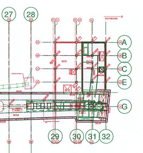
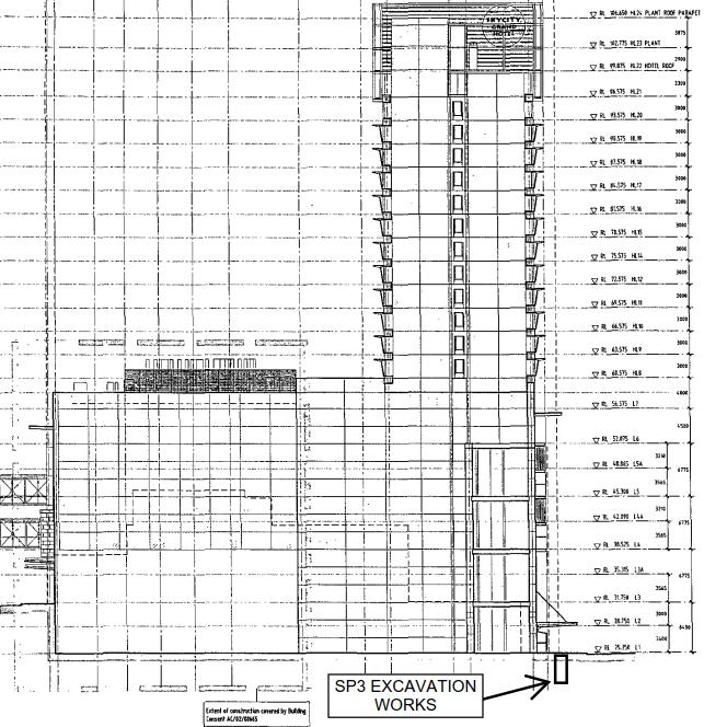
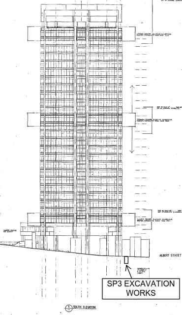
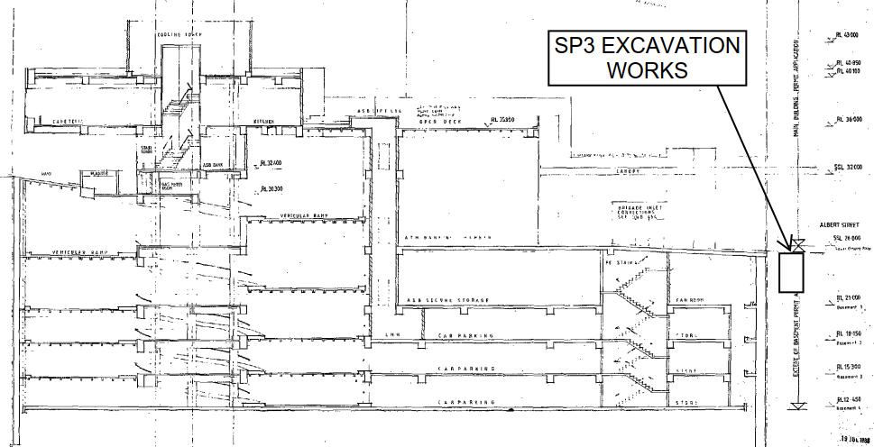
4. DESIGNS MAY BE OUT OF DATE, REFER TO REVIT MODEL FOR LATEST DESIGNS LOOKING SOUTH
NOTES:
1. THE GEOTECHNICAL INTERPRETATION OF GROUND CONDITIONS AT THIS SITE IS BASED ON OBSERVATIONS AND THE RESULTS OF TESTING AT DISCRETE LOCATIONS, AND THE CONTINUITY OF GROUND COULD VARY FROM THOSE PRESENTED ON THE DRAWING.
2. THIS INFORMATION CANNOT BE USED FOR THE PURPOSES OF PROCUREMENT OR CONSTRUCTION ACTIVITIES.
3. GEOLOGICAL MODEL DISPLAYED IS CRL-SYW-GEO-LKA-MOD-030200-B
SUBJECT Aotea Stages 4 and 5 Enabling Works – Assessment of Potential Settlement Effects
Background
This memorandum has been prepared as part of the proposed Stages 4 and 5 enabling works at Aotea Road Station, and forms part of the City Rail Link (CRL) C3 project extending from Aotea Station to the North Auckland Line (NAL).
The scope of the Stages 4 and 5 activities includes enabling works along Albert Street, Kingston Street, Victoria Street, Wellesley Street and Mayoral Drive, involving the canopy removal, utility relocation works, joint bays and construction support area establishment This memorandum does not consider the C2.1 and 2.2 Utility Works which are planned in the same area as the Stage 4 and 5 works.
The magnitude of vertical movements due to excavation stress relief depends on the dimensions of the excavation and ground conditions, construction methodology and level of support stiffness. The enabling works construction designs have yet to be confirmed at the time of writing. A conceptual high-stiffness design was therefore considered in the completion of this memorandum in order to assess the potential effects from these works on adjacent structures.
The settlement effects from the proposed Stages 4 and 5 works are expected in all cases to be negligible.
The GSMCP for the Aotea Station Stages 4 and 5 early works will adopt the trigger levels outlined in the existing Aotea to NAL Regional Resource Consent drawings CRL-SYM-RME-000-DRG-2640 Rev 4 and CRLSYM-RME-000-DRG-2642 Rev 3, as discussed and agreed with the IBA
Description of Stages 4 and 5 Enabling Works
The scope of the Stage 4 and 5 enabling works relevant to the GSMCP are summarised below. This is based on the information available at the time from the SME briefing document (30 August 2019). The proposed layout of the enabling works at the time of writing are included in the drawings included as Appendix A of this memorandum
Combined Service Trenches
Trenching for the relocation of combined services during the Stage 4 works will be completed along the Albert Street southern slip lane at the Durham Street West intersection and Albert Street service lane between Victoria Street and Wellesley Street. This trench will be in the order of 1.5m wide and 3m deep, and excavated using either a hydrovac or standard excavator
Directional Drilling
Directional drilling from Albert Street through to Federal Street is required to relocate the stormwater line in this area. These drilling works will be undertaken from the northwest corner of Albert / Wellesley Street intersection; involving a 5m deep launch and receival shaft at either end of the works and directional drilled bore between The final positions of the proposed directional drilling shafts and the directional bore diameter are still to be confirmed.
Micro-Tunnelling
The existing wastewater and stormwater lines along Victoria Street West leading up to the intersection with Albert Street will be replaced through micro-tunneling between launch/receival shafts along Victoria Street. No information regarding the dimensions of the proposed micro-tunnel works is currently available.
Shafts
Deeper stormwater and wastewater service relocation along Victoria Street West will require the provision of five shafts (Figure A2, Appendix A) to enable micro-tunnelling using a Micro Tunnel Boring Machine (MTBM). The diameter of the new stormwater and wastewater lines are 630mm and 450mm respectively.
Existing Environment
Ground Conditions
The detailed CRL Project ground conditions are described in detail in the Alliance Geotechnical Interpretative Report (GIR)1
Based on the available geological information, the general vertical stratigraphic sequence along the area of the Stage 4 and 5 works comprises the following:
Fill, asphalt or concrete pavement forms the ground surface and is underlain by granular base coarse, sub-base and/or variable fill materials, generally varying in thickness between 2 – 2.5 m along the area of the proposed works;
Alluvium deposits of Pleistocene age Tauranga Group Alluvium infills the head of a paleo-tributary gully, running towards the Queen Street valley to the east. These unconsolidated deposits comprise
1 Link Alliance, (2019). Geotechnical Interpretative Report, C3 Design Report. Reference No. CRL-SYW-GEO-LKA-RPT800006, Revision C00, dated September 2019.
clay, silt, sand and gravel, and unconformably overlie the ECBF. The thickness varies, from being absent near the Symonds Street ridge in the west up to a thickness of 9 m in the area of the main station footprint near Albert Street;
The thickness of the residual ECBF varies due to the weathering and erosion along the gully prior to being infilled with alluvium. The residual ECBF directly underlies the fill (where no alluvium deposits are present), ranging in thickness from 11 m (west of Albert Street) and 1 - 4 m (east of Albert Street).
The thicknesses of the weathered ECBF is relatively consistent along Victoria Street (approximately 3 m thick), before grading into unweathered ECBF at elevations between 0 and 10 m RL.
Hydrogeology
The detailed CRL Project hydrogeological conditions are described in detail in the PDP Groundwater Technical Report2 .
Perched Groundwater System – Maximum water levels in the Tauranga Group and residual ECBF in the region surrounding Victoria Street have been recorded at approximately 8.5 m bGL). The perched water tables are associated with more permeable lenses and are not laterally continuous, restricting the volumes of water contained in these units and the lateral migration of water in comparison to the regional aquifer below.
Regional Groundwater System - Groundwater levels within the regional system are approximately 5 m lower than levels in the overlying perched system. Seasonal groundwater level variations are likely to be less pronounced than for the upper perched units, with water level records indicating a delayed response to rainfall.
Sources of Settlement Effects
The proposed enabling works will extend to a maximum depth of 8 m bGL, and will not intersect the regional groundwater regime. Only mechanical settlement effects (i.e. vertical ground movement due to excavation stress relief from shafts, micro-tunnelling and directional drilling) are considered here.
Assessment Methodology
Tunnelling and Drilling Excavations
In order to predict the magnitude and distribution of surface settlement from the tunnelling / drilling works, information regarding the tunnel design, construction methodology and dimensions are required. In the absence of this information, this memorandum considers the potential maximum vertical settlement that could be expected for a range of conceptual tunnel design scenarios using published empirical methods
The maximum vertical settlement was calculated for a range of potential tunnel diameters at hypothetical depths of 4, 6 and 8 m bGL, and using the method proposed by Mair (1993)3. A volume loss of 1% and trough width coefficient of 0.5 were assumed in the absence of confirmed design values.
Trench and Shaft Excavations
2 PDP, (2016). Auckland City Rail Link Aotea Station to North Auckland Line Construction and CRL Operation: Groundwater Technical Report. Prepared for Aurecon on behalf of Auckland Transport, dated May 2016.
3 Mair, R.J. (1993). Developments in geotechnical engineering research: application to tunnels and deep excavations, Unwin Memorial Lecture 1992, Proceedings Institution of Civil Engineers. Civil Engineering, Vol. 93, pp.27-41.
A conceptual design, comprising a high-stiffness excavation support system and top-down construction methodology was assumed in order to predict the magnitude and distribution of surface settlement from the Stage 4 and 5 excavations, following the approach summarised in CIRIA (2003)4
Results
Combined Service Trenches
The combined service trenches along Albert Street will have a maximum depth of 3m. Adopting the empirical assessment method outlined above, maximum deformations from the proposed trenches at the positions of the buildings are expected to be less than 3 mm (Figure 1).
Tunnelling and Drilling
The expected settlements at surface for a range of tunnel/bore diameters at different depths are summarized in Figure 2 below. Assuming a depth of 4m bGL and micro-tunnel/bore diameters of 0.5, 0.7 and 2m (to account for single large diameter or multiple small diameter tunnel scenarios), the maximum vertical settlement ranges from < 1mm to 6mm. The reported settlement values are assumed to occur at a point on surface overlying the centerline of the tunnel/bore, and will decrease with increasing distance from the excavation centerline (Figure 3).
4 CIRIA C580, (2003). Embedded Retaining Walls – Guidance for Economic Design. London, ISBN 0 86017 580 4, 390 pp.
Figure 1: Relationship between settlement and distance from excavation, assuming 3m deep trench and building 1m away from edge of excavation (CIRIA, 2003)
Tunnel diameter [m]
Estimated settlement - 4m deep [mm]
Estimated settlement - 6m deep [mm]
Estimated settlement - 8m deep [mm]
Poly. (Estimated settlement - 4m deep [mm])
Poly. (Estimated settlement - 6m deep [mm])
Poly. (Estimated settlement - 8m deep [mm])
2: Predicted maximum surface settlement for various diameter tunnels at hypothetical depths of 4, 6 and 8 m bGL (Mair, 1993)
Distance from tunnel centerline [m]
3: Distribution of settlement from tunnel centreline5 Shaft Excavations 5Burland, J. B. (1995). Assessment of
2m Diameter
0.7m Diameter
0.5m Diameter
Figure
Figure
Adopting the conceptual design and empirical method outlined above, the resulting ground surface deformations from the proposed shaft excavations are summarised in Table 1 below.
Table 1 Expected maximum ground surface settlements beneath buildings adjacent to shafts
Excavation ID
A1 and A2, Appendix A)
*Assumed, positions to be confirmed
Effects of Enabling Works
Buildings adjacent to the Stage 4 and Stage 5 works include structures founded on either shallow or piled footings (with and without basements). The tolerance of a structure to distortions imposed by ground movement (total and differential settlement of the foundation system) is unique and is dependent on building materials, foundation systems (shallow or piled), construction quality, and the existing condition of the structure.
Effects on Buildings – Piled Footings
The following excavations are proposed adjacent to building with piled foundations:
Table 2 Depth of excavation compared to adjacent building details
* Approximate elevation
The final invert level of the proposed Shaft 1 may extend to a greater depth than the bottom of the floor slab of the basement of the AA centre. Considering the predicted settlement values from the assessment in this memo, resulting deformations at the edge of the building are expected to be < 5 mm. Any subsequent effects on the adjacent building and basement slab of the AA centre are therefore expected to be negligible.
All other Stage 4 and Stage 5 excavations are shallower than the basement excavation and piled foundation depths of adjacent buildings, and the effects of these on adjacent piled structures are expected to be negligible.
Effects on Buildings – Shallow Footings
Combined service trenches, micro-tunneling and shaft excavation activities are planned adjacent to buildings with shallow foundations (ID No’s: 11, 12, 13, 14, 114).
The method outlined in Burland (1995) has been adopted to assess the likely effects on nearby buildings due to ground movement induced by the Stage 4 and 5 works. This approach is the most commonly used and recommended method to assess the effects of ground movement and has been widely used for similar projects across Auckland including City Rail Link C2 and the Waterview Connection.
The method assesses the effects on nearby buildings in a series of stages of increasing complexity, where buildings are screened based on the outcome of the previous stages. The buildings are removed from further assessment when the level of risk is within defined tolerances.
The preliminary assessment identifies nearby buildings where the construction induced ground movement will likely have a negligible effect. Burland (1995) recommends the criteria defined in Rankin (1988)6 which states that buildings experiencing settlements less than 10 mm and a maximum differential settlement of 1:500 are expected to have insignificant damage potential.
The expected surface settlements at all shallow foundation buildings in close proximity to the enabling works is < 10 mm. The settlement effects from these enabling works are therefore expected to be negligible.
Concluding Remarks
The settlement effects from the proposed Stages 4 and 5 works are expected in all cases to be negligible. Ground deformation will be monitored against a set of intermediate trigger levels. The intermediate levels will be set once the AEE for the main works is completed to confirm that the envelope of effects of the main works and enabling works comply with the levels set out in the Consent.
6 Rankin, W. J. (1988). Ground movements resulting from urban tunnelling: predictions and effects. Geological Society, London, Engineering Geology Special Publications, 5(1), 79-92.
Prepared
by:
George Brink
Lead – Groundwater and Settlement Effects
Reviewed by:
Graeme Twose
Senior Geotechnical Engineer
Figure A1: Stages 4 and 5 Enabling Works relevant to GSMCP
Figure A2: Stages 4 and 5 Enabling Works Micro-Tunnelling Shaft Layout
APPENDIX E: Response to Reviewer Comments
Table F-1 Response to reviewer comments
Item No.
Reviewer Comment
1. In Section 2.1 and on the plan ( Figure A2 attached to the memo dated 17 October 2019) - Please clarify which shafts are proposed to be 8m deep and which are proposed to be 4m deep, and also on Figure A2 please show the distance of Shaft 5 from the nearest building.
2. Section 3.2 refers to a representative geological section along Victoria St West which is included in Appendix A of the GSMCP – The Section should be enlarged to show the Stage 4 & 5 works (Shafts and micro-tunnelling) and both perched and regional ground water level information included for clarity.
3. A similar geological cross-section to that provided in Appendix A should be provided to show the Stage 4 & 5 works (Directional drilling and shafts) along Wellesley Street West.
4. Section 3.3 describes the hydrogeological conditions that are relevant to Victoria Street West, this Section should be expanded to include a description of the hydrogeological conditions that are relevant to Wellesley St West.
5. In Section 3.7 - please confirm if any of the proposed Stage 4 and 5 works will intersect the perched groundwater table
6. We consider that the information provided Section 6.5 and Appendix D is inadequate as there has been no assessment of the ground surface settlement likely to be induced by Stage 4 and 5 works. It is noted in Appendix D, Table 1: Lateral Deflection Limits that there is an assumption that the retaining walls for the five shafts in Victoria Street West and the two shafts in Wellesley Street West will be designed with a maximum tolerable deflection of 10mm. It is considered that it should be possible, at this time, for LA to demonstrate that this is achievable for a concept retaining design, even if only using empirical analysis methods. Once this has been completed an assessment of effects on buildings adjacent to the retaining walls for the shaft/pit/trench excavations is required taking into account the foundation type and separation distance.
Link Alliance Response
Section 2.1 and Figure A2 (Appendix D) updated with required information
Section updated.
Section added.
Section 3.3 updated with description of regional hydrogeological conditions.
Updated to discuss perched groundwater.
Section 6.5 and Appendix D have been updated to assess the effects of the proposed Stages 4 and 5 works, adopting a conceptual, high-stiffness excavation support system. The assessment is based on empirical settlement estimation methods as outlined in the memorandum.
7. Please confirm that the predicted settlement for the Early Works at Aotea Station when superimposed on the predicted settlement for the Main Works at Aotea Station will fall within the consented settlement envelope shown on the attached Aotea to NAL Resource Consent Drawings ( CRL-SYE-RME-000-DRG 2610 Rev 3, CRL-SYE-RME-000-DRG 2640 Rev 4 and CRL-SYE-RME-000-DRG 2642 Rev 3 ) including the “Differential vertical slope across the buildings”.
8. Section 6.3.4 should be revised such that buildings on shallow foundations and piled buildings with no basements adjacent to the proposed excavations should have post-construction detailed condition surveys undertaken after completion of the Early Works but prior to commencement of the Main Works.
The design and AEE for the Aotea Station main works have not been finalised, and it is not possible to superimpose the predicted settlement contours from the two construction stages at this time. The cumulative effects from the two stages of works will be assessed in the AEE for the main works, taking into account the ground movement recorded during the completion of the early works.
The resource consents conditions require: building condition survey (BCS) pre-construction (c109), additional measures at sensitive building (c112), visual inspection of ground and external facades of listed building (c113), and completion of construction monitoring (c115). The GSMCP is based on these requirements.
BCS will only be completed after completion of construction (i.e. after completion of the main station works). The Link Alliance will carry out a visual inspection of the surrounding ground and external building facades of the buildings adjacent to the works to monitor any deterioration or further cracking of any pre-existing cracks (as required by c113). If a complaint is made around building damage following completion of the early works, a post-early works construction BCS will be carried out for that particular building (as per c116).
9. Section 6.4 – Utilities and Infrastructure - Post Construction Settlement Monitoring refers to Karangahape Station Main Works and buildings –Please revise Amended.
10. Please provide clarification as to why monitoring is proposed for Building ID No. 21 ( 109-125 Albert Street)
Monitoring of Building ID. 21 will form part of the SP 2.2. utility relocation works along Albert Street. The Stages 4 and 5 instrumentation and monitoring plan has been amended to remove this structure.
Table F-2 Response to additional reviewer comments Item No. Reviewer
6. Please check the alert and alarm trigger levels for horizontal movement at building face of 13mm and 17 mm for Building ID No. 22 – 135 Albert Street in Appendix B -Table B2. The consented alert and alarm trigger levels for horizontal movement at building face are 6mm and 9mm for this building.
It is noted that in the memo presented in Appendix D there is no indication if there would be another set of early works performance trigger levels given to the contractor for the proposed monitoring. This approach was proposed for the Stage 1 to Stage 3 early works for Aotea Station. Please confirm that Link Alliance will be following a similar approach of providing another set of early works performance trigger levels to the contractor for the Stage 4 and 5 early works.
We note that proposed Shaft 1 is to be excavated to a depth of 4m in Victoria Street West is located within the footpath and in very close proximity to two columns which appear to be supporting the canopy attached to the building at 99 Albert Street. It is considered likely that these two columns will have shallow foundations. We request that the settlement effects on these columns is assessed and consideration given to additional monitoring on this columns.
8. We note that proposed Shaft 3 is to be excavated to a depth of 8m in Victoria Street West and will be located approximately 4.3m from Building ID No. 11 –71 Victoria Street West and Building ID No. 12 – 69 Victoria Street West. These two buildings are constructed on shallow foundations and we note that the predicted settlement at the buildings as result of the proposed shaft construction is 6.5mm i.e. > 5mm. We consider that these two buildings should have post-early works detailed Building Condition Surveys.
Table B2 updated with the Consent trigger levels for horizontal movement.
Ground deformation will be monitored against a set of intermediate trigger levels See response to Item No. 8.
The predicted settlement effects from Shaft 1 is ~ 3mm at a distance 0.1m from the excavation (Table 1, Appendix D), and will decrease with increasing distance from the excavation. The effects on the columns due to such settlements are expected to be negligible.
The nature of these buildings was considered in the original response to Comment No.8 (Table F1), and the effects from the predicted settlement are expected to be negligible BCS will only be completed after completion of construction (i.e. after completion of the main station works) and in accordance with the conditions of the Consent.
In relation to external visual inspections in Section 6.2.3 it is stated “This will be carried out at least quarterly from the commencement of any dewatering/excavation until completion of excavation”. We consider that this frequency is not appropriate for the short-duration early works and that the following text should be added “or (in the event of shorter duration activities) within 1 week of completion of the works”.
If Link Alliance intend to provide another set of early works performance trigger levels the contractor for the proposed monitoring, then they should be requested to provide an undertaking to supply details of the early works performance trigger levels, and the proposed actions if the early works performance alert and alarm trigger levels are exceeded, once the preconstruction BCS have been completed.
If Link Alliance provide this undertaking, together with confirmation of the revised frequency of external visual inspections, and a satisfactory responses to queries 6 and 8, then FTL will be able to recommend that Council certify the GSMCP and the addendum memo.
Section 6.2.3 updated to make provision for short-duration activities.
The intermediate levels will be set once the AEE for the main works is completed and to confirm that the envelope of effects of the main works and enabling works comply with the levels set out in the Consent.
From: Mark Foo <MarkFoo@qdesignz.co.nz>
Sent: Tuesday, 5 November 2019 9:39 AM
To: George BRINK
Subject: FW: IBA Review of Draft Early Works GSMCP's Attachments: 20191016_IBA Review Letter.pdf
Hi George
I refer to your email below (including your attached letter of 16 October 2019) and also to our meeting at your offices on 11 October 2019
I understand that Link Alliance’s engineers are of the opinion that the proposed early works at Karangahape or Aotea is not expected to interest the regional ground water table and no consolidation effects due to dewatering are anticipated.
I also understand that you propose to implement ground surface settlement monitoring and contingency mitigation measures to identify and address any possible mechanical settlement effects.
In view of the above, I have no objection to your proposal to the Link Alliance adopting the current consent GSMCP trigger levels for the Aotea and Karangahape projects provided the monitoring measures are installed prior to commencement of excavation works.
Dr Mark Foo Director
PhD, BE(hons), CPEng, CMEngNZ, IntPE, MIEAust, CPEng NER
Notice: This email is intended only for the use of the individual or entity named above and may contain information that is confidential and privileged. If you are not the intended recipient, you are hereby notified that any dissemination, distribution or copying of this email is strictly prohibited. Any opinions expressed in this email are those of the author and do not necessarily reflect the views of Q Designz Limited. We will not accept responsibility for any commitments made by our employees outside the scope of our business. We do not warrant the accuracy or completeness of such information.
P Please consider the environment before printing this e-mail
From: George BRINK <george.brink@linkalliance.co.nz>
Sent: Monday, 4 November 2019 9:19 AM
To: Mark Foo <MarkFoo@qdesignz.co.nz>
Subject: FW: IBA Review of Draft Early Works GSMCP's Importance: High
Good morning Mark,
Following up on the email below;
- Are you able to please respond to the attached letter, confirming your agreement with the approach we discussed during our meeting early October? A response to the email, confirming your agreement, will be fine.
- We have a statement in the GSMCP’s referring to Resource Consent Conditions 96 and 97 (“The GSMCP shall be prepared and submitted by the Consent Holder (CRLL) to the Manager (AC) for certification at least 20 working days prior to the Commencement of Dewatering, together with a statement from the IBA [Independent Building Assessor] confirming its adequacy.” and “The procedures referred to in Condition 96 shall be set out in a GSMCP, prepared and submitted by the Consent Holder at least 20 working days prior to the Commencement of Dewatering, together with a statement from the IBA confirming its adequacy, to the Manager for certification.”. We have submitted the Karangahape Station early works GSMCP to Council. One of the reviewer (Fraser Thomas) comments were that they are yet to receive the statement referred to in the conditions above. I have previously sent you the link to the GSMCP’s (email below), are you able to please confirm and submit the required formal statement to enable certification of these plans?
Please give me a call if anything is unclear.
Regards,
George
George Brink – Groundwater and Settlement Effects
Link Alliance | Level 3, 12 Morgan Street, Newmarket, Auckland 1023
M +64 27 593 0993 | P +64 9 352 2929 | E george.brink@linkalliance.co.nz
Thank you again for meeting with us this past Friday (11 October 2019) to discuss our approach to the GSMCP’s currently being prepared for the early works at Karangahape and Aotea Stations.
Following on from this:
a) The attached letter has been prepared following the meeting held between the Link Alliance and yourself on Friday 11 October 2019, and provides a summary of the main points of discussion. Could you please confirm your agreement in principle to the approach being adopted by the Link Alliance, and as set out in Points i) and ii) of the attached letter, by COB 17 October 2019.
b) I have uploaded the draft GSMCP’s with supporting appendices for the Aotea Stages 4 and 5 Early Works and Karangahape Station Early Works to the link below. Both the aforementioned management plans have been prepared following the approach as discussed and covered in Point a) above. Keeping
this in mind; can you please review and confirm the suitability of the proposed settlement monitoring and mitigation measures the Link Alliance have included as part of these plans.
Link to draft GSMCP’s for review: https://transfer.tonkinandtaylorgroup.com/message/epB0SDrQCIuMYIOZCi9y8x
Please get in touch if you have any question or require any further information.
Regards,
George Brink – Groundwater and Settlement Effects
Link Alliance | Level 3, 12 Morgan Street, Newmarket, Auckland 1023 M +64 27 593 0993 | P +64 9 352 2929 | E george.brink@linkalliance.co.nz
APPENDIX
This page intentionally left blank.
GLOSSARY OF TERMS
Term Definition
AC
AT
Auckland Council
Auckland Transport
ATS Automatic Total Station
BCS Building Condition Survey
CBD Central Business District
CEMP Construction Environmental Management Plan
CEP Construction Execution Plan
CPEng Chartered Professional Engineer
CRL City Rail Link
CRLL City Rail Link Ltd
CSA Construction Support Area
ECBF East Coast Bays Formation
EMS Environment & Sustainability Manager
GNS Geological and Nuclear Sciences
GSMCP Groundwater and Settlement Monitoring and Contingency Plan
IBA Independent Building Assessor
LQS Lower Queen Street
m RL Metres reduced level
TG Tauranga Group
QE2S Queen Elizabeth II Square
1 INTRODUCTION
1.1 SCOPE
The City Rail Link (CRL) project comprises the construction, operation and maintenance of a 3.4 km underground passenger railway, running between Britomart Station and the North Auckland Rail Line in the vicinity of Mt Eden station.
This Groundwater and Settlement Monitoring and Contingency Plan (GSMCP) relates to CRL Contract 2 Separable Portion 3 (SP3; the Project) which involves the removal of existing building canopies from four buildings and diversion of underground utilities within the Albert Street road corridor from Victoria Street West to Wellesley Street West. The Project includes trenching and is expected to take 12 months to complete.
Figure 1 outlines the extent of works for the Project
This project is being delivered by Connectus, a joint venture of McConnell Dowell Constructors Limited and Downer New Zealand Limited. The GSMCP has been prepared by AECOM New Zealand Limited (AECOM) for Connectus and forms part of the Construction Environmental Management Plan (CEMP) for the Project.
The relevant resource consent for the GSMCP is Water Permit R/REG/2016/1892 for the Take and Diversion of Groundwater (the Consent)
The Consent will expire 35 years after the consent commences unless it has been surrendered or been cancelled at an earlier date.
Figure 1 Extent of Project Works
From PTA (26 May 2017).
1.2 PURPOSE OF GROUNDWATER AND SETTLEMENT MONITORING AND CONTINGENCY PLAN
1.2.1 ObjectivesoftheGSMCP
The objectives of the GSMCP are to:
a) So far as reasonably practical, avoid any damage that affects serviceability of structures and services; and
b) To remedy or mitigate any adverse effects (including cumulative effects) associated with dewatering/excavation and excavation activities required for the CRL tunnel construction.
This GSMCP, prepared in general accordance with Conditions 82 to 129 of the Consent described below (Section 1.4), outlines the Project requirements for:
The monitoring of groundwater and settlement effects outlined in the Assessment of Environmental Effects (AEE) report;
A framework for developing monitoring and mitigation procedures to minimise the effects of settlement on existing structures;
Building condition survey review.
The GSMCP is required to be certified by Auckland Council (AC) at least 20 working days prior to the commencement of dewatering/excavation. No dewatering/excavation on the subject site shall commence until certification from AC is provided.
This GSMCP may be varied (including the frequency of monitoring), subject to certification of the variation by AC, and shall be implemented for the periods specified in the Consent.
1.2.2 PerformanceStandardsduringConstruction
Further to the objectives of the GSMCP as described above, the following performance standards are specified within the Consent:
Within the 5mm settlement contours on the drawings in Appendix 1, all excavations, dewatering systems, retaining structures and associated works (including backfilling) for the CRL construction must be designed, constructed and maintained so as to avoid any damage that exceeds the Serviceability Limits of buildings, structures and services.
Beyond the 5mm settlement contours on the drawings in Appendix 1, the Consent Holder must ensure that the damage to masonry buildings due to the Project works, including excavations, dewatering systems, retaining structures and associated works (including backfilling), does not exceed the “negligible” category extent detailed in Table 1 below and has only negligible effects on piled buildings, structures and services.
The predicted settlement and building assessment is included in Appendix C.
1.2.3 PredictedPerformance
These performance standards will be achieved through the design of the Project, and the effects of dewatering/excavation will be mitigated through the procedures and actions provided in Sections 5, 6, and 7 of this GSMCP.
During the detailed design of the Project the predicted effects of settlement arising from the final ground support design have been assessed and are documented in AssessmentofSettlement Effects attached as Appendix C
Based on this assessment damage to buildings from the Project is predicted to fall within the “Negligible” damage classification
1.3 GSMCP AUTHORS
This GSMCP has been prepared under the direction of a senior qualified person (Geotechnical Professional), Kevin Anderson BEng(Hons) CPEng
Kevin is an Associate Director – Geotechnical at AECOM. He has a Bachelor degree in Civil Engineering, is a Chartered Professional Engineer and has over 21 years’ experience in geotechnical assessment including considerable experience in undertaking, managing, and reporting on geotechnical investigations for public and private sector clients.
1 Burland J B (1997), Assessment of risk of damage to buildings due to tunneling and excavation, Earthquake Geotechnical Engineer ing, Ishihara (ed), Balkema, Rotterdam, pp. 1189-1201.
1.4
CONSENT REQUIREMENTS
Table 2 outlines the resource consent conditions specific to the GSMCP for Water Permit R/REG/2016/1892 and how these are addressed within this GSMCP.
a.
built” survey plan of all monitoring locations
b. full details of the existing groundwater environment, surveys and monitoring required by the Consent
Section 3 (Existing Environment)
Section 4 (Overview of Monitoring and Reporting Requirements)
Section 6 (Settlement Monitoring Plan)
c. details on the timing and frequency of the required surveys and monitoring relative to the commencement of dewatering/excavation and the completion of dewatering/excavation; Relevant details are outlined in:
d. details outlining the effects on groundwater
e. alert and alarm triggers for each ground and building deformation mark
f. details of contingency measures to be implemented if alert or alarm triggers are exceeded including a Response Plan
g. identification of any adjacent services susceptible to damage and details of any pre and post construction monitoring or inspection;
. details of monitoring proposed to be at all adjacent buildings against cumulative settlement effects;
. identification of, and monitoring of, existing basements which could be subject to potential flooding from post-construction groundwater mounding.
k. review of the proposed monitoring frequency, and alarm and alert trigger levels in Appendix B (following the construction building condition surveys required by Condition 109) to confirm they are appropriately set to ensure the “slight” damage category will not be breached.
101 The GSMCP may be varied, including frequency of monitoring, subject to the certification by AC.
102 Once certified, the GSMCP shall be implemented for the periods specified in the conditions of the Consent.
103 The Consent Holder shall advise the Manager, in writing, of the date of the proposed Commencement of Dewatering. Building
Prior to the commencement of dewatering/excavation, the Consent Holder shall employ an independent senior qualified person to undertake a detailed pre-construction condition survey, of all buildings specified in Section 6.2.1 to confirm their existing condition, subject to the approval of the property owner. The survey shall include, but not be limited to, the following:
a. any information about the type of foundations;
b. existing levels of damage considered to be of an aesthetic or superficial nature;
c. existing levels of damage considered to affect the serviceability of the building where visually apparent and without recourse to intrusive or destructive investigation;
d. a professional opinion as to whether observed damage may or may not be associated with actual structural damage;
e. susceptibility of the building or structure to further movement;
f. specific assessment of building damage from the predicted total settlement shown in Appendix C and with reference to the trigger levels identified in Appendix B;
g. review of proposed alarm and alert trigger levels to confirm they are appropriately set and movement less than trigger levels set will not exacerbate damage, and whether the monitoring frequency and locations of monitoring points are adequate; and
h. photographic evidence of (b) and (c).
Section 4.1 and Table 3
Section 5
Section 6, Appendix B
Section 7
Section 6.4
Section 1, 6.2.1 and 6.3.1, Appendix A
Section 3.5
Section 8.2
Section 1.2.1 and 8
Section 1.2.1
Section 6.2
110
declined (or unreasonable terms imposed) to undertake
Any condition survey undertaken in accordance with Condition 109, or any other condition surveys undertaken by the Consent Holder, shall be undertaken as follows:
a. The senior qualified person shall be identified in the CEMP (required by Condition 36);
b. Contact owners of those buildings and structures where a condition survey is to be undertaken to confirm the timing and methodology for undertaking a pre-construction condition survey;
c. Record all contact, correspondence and communication with owners and this shall be available on request for the Council;
d. Provide the building condition survey or structure condition survey report to the relevant property owner and the Council within 15 working days of the survey being undertaken;
e. Undertake a visual inspection during construction if requested by the building or structure owner where a pre-construction condition survey has been undertaken;
f. Develop a system of monitoring the condition of existing buildings or structures which is commensurate with the type of the existing building or structure and the proximity of the project works in order to assess whether or not construction activities are compromising the structural integrity of the building or structure.
112 Should the pre-construction building condition survey and assessment highlight greater sensitivity of buildings than envisaged by the application, then implement additional measures.
113 Carry out a visual inspection of the ground and external building facades of the listed buildings to monitor any deterioration or movement of any deterioration or movement of
existing cracks.
114 Keep a record of the time, date and any observations for each inspection
115 Timing of post-construction building condition survey. Survey to cover the matters identified in Condition 111
116 Additional building condition surveys at the request of AC.
117 Subject to Condition 125, the requirement for any such condition survey will cease 6 months after the Completion of Construction, unless the requirements of Condition 115 have not been met and subject to a consistent pattern of deformation records having been obtained in this period in which no evidence of adverse effects is apparent.
119 Establishment and maintenance of a settlement monitoring network (ground settlement and building movement monitoring marks) to detect any deformation:
a. The minimum scope of settlement monitoring
b. Subject to the owners’ approval, at least two sets of building movement monitoring marks shall be located on each building
c. The final location and number of building movement monitoring marks shall take into account the building type and size, accessibility to survey the marks and risk of damage from ground settlement and the effects of differential settlement from the predicted settlement values.
Section 7
Section 6
Appendix A
120 Monitoring frequency and duration, and baseline monitoring records. Section 6.3, Table 4
In response to the event of any Alert or Alarm trigger level exceedance (ground surface, building and/or groundwater levels**) the following shall occur:
a. Notify AC and the IBA within 24 hours;
b & c. If alert values are exceeded, a senior qualified person shall assess the works constructed up to that time and provide a report to AC within one week. Measures (if any) to be implemented are to be as identified in the GSMCP.
d. If alarm values are exceeded, the process outlined in Condition 124b shall be undertaken. The report shall also include any recommendations for remedial actions if required in order to complete construction. These recommendations shall be implemented prior to recommencing works.
e. Where alarm levels are exceeded, remedial recommendations and actions of the IBA may also be considered. This shall be implemented, unless the building owner(s) request in writing that the construction works are to be completed in accordance with the report prepared under Condition 124d.
The required response and repairs should any damage to buildings, structures or services be caused wholly or in part by the exercising of the
The conditions of the Consent may be reviewed by
2 PROJECT DESCRIPTION
This section presents a summary of the Project works that relate to the matters required to be addressed by the GSMCP. A detailed description of the construction methodology is provided in the Project CEMP.
The relevant construction period for this GSMCP occurs from the time that dewatering/excavation commences (Section 2.1)
2.1 SUMMARY OF CONSTRUCTION METHODOLOGY
The Project involves excavating a trench along Albert Street, between Wellesley and Victoria Street, to relocate underground services. This will simplify the future construction of the proposed Aotea train station. The excavation for the Project (i.e. SP3) is approximately 200m long, 4m deep and 1.5m wide. To complete the excavation, overhanging canopies attached to the adjacent buildings will be amended.
Generally, the Project works undertaken will consist of:
1. Canopy removal along the western side of Albert Street (between Victoria Street and Wellesley Street)
2. Trench excavation, ground support and spoil handling
3. Relocate/install/abandon underground utilities
4. Backfill the trench and reinstatement the road pavement.
The trench will be approximately 4m deep, 1.5m wide and 200m long. It will predominantly be within well compacted fill overlying stiff Tauranga Group alluvium. The ground support for the trench will be a proprietary system providing positive ground support.
Network utility operators that will be affected by the works include Vector Electricity and Communications, Vector Gas, Chorus, Auckland Council, Watercare and Vodafone. The method of relocating, protecting and supporting each utility has been developed in consultation with the relevant utility operator and depends on the type of utility and its location.
2.1.4 Trenchbackfilling
The trench backfill will be placed progressively as the utility works are completed and the temporary ground support removed. The pavement will then be reinstated
3 EXISTING ENVIRONMENT
3.1 LAND USE AND TOPOGRAPHY
The Wellesley to Victoria Street section of the Project is situated in the Auckland Central Business District (CBD). The CBD is a high density built-up urban environment and New Zealand’s largest city centre, with no natural ground surface evident. Current land uses above ground along the Project alignment include high density commercial and office buildings, residential and visitor accommodation, retail, restaurants and bars. Numerous underground services (utilities) are present within the CBD and Project Area.
The topography of the CBD is characterised by ridges and valleys and has a gentle sloping topography, dropping from south to north towards the coast. Intersecting streets strike east-west down the valley slopes to Queen Street (e.g. Victoria and Wellesley Streets) and are steep relative to Albert Street.
3.2 GEOLOGY
Geological and Nuclear Sciences (GNS) has published a 1:50,000-scale geological map of the Auckland urban area2 . The general vertical stratigraphic sequence comprises the following, in chronological order (oldest to youngest):
East Coast Bays Formation (ECBF): is present at depth, which forms the local basement rock. The ECBF is characterised by alternating sandstone and siltstone beds with a completely weathered (residual soil) upper surface. The unweathered rock is fractured to a varying degree.
Tauranga Group Sediments (TG): alluvial and marine sediments comprising peat, mud, silt, sand and gravel, which unconformably overlie the ECBF. These are present as unconsolidated sediments that are frequently interlayered and may form discrete lenses at some locations.
Albert Park Volcanics: Basalt and scoria produced from Albert Park Volcano form considerable thicknesses within the CBD, particularly on the eastern side of Queen Street, into the Queen Street Valley. Volcanic ash deposits of variable thicknesses are present at discrete locations overlying the Tauranga Group and ECBF throughout the Project area.
Fill: asphalt or concrete pavement forms the ground surface and is underlain by granular base coarse, sub-base and/or variable fill materials. Fill materials may comprise re-worked natural soils (silts, sands and gravels) or waste materials such as ash, clinker and demolition rubble. The thickness of each unit varies across the Project area. Site specific geology has been determined from boreholes and other site investigations in the vicinity of the Project and has been documented in factual and interpretive reports.
3.3 HYDROGEOLOGY
Key aspects of the hydrogeology are summarised here
2 Kermode, L. O. 1992: Geology of the Auckland urban area. Scale 1:50 000. Institute of Geological & Nuclear Sciences Geological Map 2. Lower Hutt, New Zealand, Institute of Geological & Nuclear Sciences Ltd. 1 sheet + 63 p.
3.3.1
GroundwaterSystem
Two key groundwater systems have been identified for the Project:
Shallow perched system - within the Tauranga Group sediments, upper weathered ECBF and local volcanic ash/fill materials. This system comprises numerous perched and isolated water tables, supported by lenses of low permeability materials and the weathered ECBF. Areas of saturation are expected to be laterally discontinuous.
Deeper (regional) groundwater system – within the ECBF this aquifer underlies the shallow perched groundwater system and is a continuous zone of saturation. In areas of higher topography, some perching on discrete mudstone layers may be present within the ECBF.
Seasonal groundwater level variations are likely to be less pronounced within the regional groundwater system than for the upper perched units, with water level records indicating a delayed response to rainfall.
Groundwater flow in both systems is generally in a northerly direction toward the Waitemata Harbour. Locally, groundwater flow is interpreted to be influenced by topography, promoting flow to the northeast toward the Queen Street Valley.
Buildings along this part of the alignment that have drainage systems all report little if any discharge.
3.3.2
Groundwaterlevels
Groundwater Levels within the shallow perched aquifer and regional ECBF are described below:
Perched groundwater - water levels in the Tauranga Group and volcanic deposits near Victoria Street have been recorded at approximately 15 m RL. Significant water level responses occur in the perched units after rainfall events, with about 0.4 m increase in water level following a rainfall event. Seasonal groundwater level variations are likely to be about 2.0m.
Where encountered, perched groundwater heads in the shallow system of 1 to 2 metres have been recorded, with this expected to be variable as a function of material heterogeneity and presence of services/basements which act to drain the shallow groundwater. The perched water tables are associated with more permeable lenses and are not laterally continuous, and this restricts the volumes of water contained in these units and the lateral migration of water in comparison to the regional aquifer below.
Regional ECBF Aquifer- groundwater levels within the regional system are approximately 5 m lower than levels in the overlying perched system. The following regional ECBF water levels have been measured and are subject to seasonal variation:
Victoria Street – between approx. 6 and 8 m RL (16 – 19 m depth).
Wellesley Street – approx. 10 m RL (15 m depth)
Seasonal groundwater level variations are likely to be less pronounced than for the upper perched units, with water level records indicating a delayed response to rainfall.
3.3.3
GroundwaterFlowDirection
Groundwater generally follows a subdued expression of topography. However, localised differences between shallow perched groundwater and the deeper regional flow area are expected as follows: Perched groundwater – variable groundwater flow is expected within the shallow perched system as a function of material heterogeneity, the influence of drainage to service trenches/basements and the palaeotopography of the ECBF. A component of water flowing in the perched system will recharge the underlying regional aquifer. The perched groundwater regime is complex and has already been extensively modified from its natural condition by the extensive building development, filling and existing utilities acting as drains and connections between lenses.
Regional ECBF Aquifer –groundwater flow in the regional aquifer is generally in a northerly direction toward the Waitemata Harbour. Locally, groundwater flow is interpreted to be influenced by topography, promoting flow to the northeast toward the Queen Street Valley.
3.4 EXISTING BUILDINGS AND STRUCTURES
The types of buildings encountered along and adjacent to the Albert Street section (between Victoria and Wellesley Street) are multi-storey piled structures that are used for a mix of residential, entertainment, commercial and retail.
The following buildings are of interest and have had individual settlement assessments and building condition surveys These are:
Auckland Council Tower – 135 Albert Street
SKYCITY Convention Centre – 109 – 125 Albert Street
Manhattan Apartments – 101 – 107 Albert Street
AA Centre – 99 Albert Street
3.5 EXISTING BASEMENTS
The following list outlines the basements present adjacent to the excavation:
Auckland Council Building – 4 levels
SKYCITY Convention Centre – 4 levels
Manhattan Apartments – 1 level
AA Centre – 1 level
As shown in Appendix C, the size and depth of excavation is much smaller than the depth of basement and size of existing foundations.
3.6 EXISTING UTILITIES
There are a number of network utilities which run across or close to the trench excavation. The utilities expected to be encountered include stormwater, wastewater, potable water, electricity, telecommunications and gas. Due to the variable age of all utilities within the CBD, it is expected that the condition of these utilities will likely be variable and will not be known until they are exposed
4 OVERVIEW OF MONITORING & REPORTING REQUIREMENTS
This section provides an overview of the monitoring and reporting required by the Consent (refer to Sections 5 and 6 of this GSMCP for detailed monitoring plans).
4.1 CONSTRUCTION STAGES
There are three main construction stages, each with particular monitoring and reporting requirements (Table 3):
Table 3: Monitoring Requirements for each Construction Stage Stage
Before dewatering/excavation (Baseline)
January 2018 to February 2018
During excavation July 2018 to June 2019
This monitoring phase will provide baseline data against which effects resulting from the bulk excavation works can be assessed. Data required by the Consent for this stage of works will be compiled in a factual report prior to the commencement of construction dewatering/excavation with any irregular results further assessed. The outcomes will form part of the input for the construction phase assessments.
Monitoring during the bulk excavation phase will be used to verify the design analyses, by comparing the actual measurements with those estimated. The monitoring data will be used to reassess the building damage classifications at critical locations. If these reassessments indicate that the damage classifications have increased significantly then additional analyses, increased monitoring or other actions may be required. Mitigation options, discussed in Section 7 of this GSMCP, may also be required to be implemented.
After dewatering/excavation
May 2019 until stable
Where specified in the Consent, monitoring will occur until the various stages of works are completed (excavation and construction), and shall continue until stable measurements are demonstrated and written approval is provided by AC to cease monitoring.
4.2 NOTIFICATION AND GSMCP CERTIFICATION
Connectus will advise AC in writing of the date of the proposed commencement of dewatering/excavation
As defined in the Consent, commencement of dewatering/excavation means commencement of bulk excavation and/or any dewatering prior to excavation.
The GSMCP is required to be certified by AC at least 20 working days prior to the commencement of dewatering/excavation, and dewatering/excavation on the site will not commence until certification from AC is provided.
4.3 DATA COLLECTION AND REPORTING REQUIREMENTS
All data collected as required by conditions of the Consent from commencement of excavation to completion of monitoring will be compiled, compared with the relevant trigger levels and submitted to AC at two monthly intervals by those responsible (refer Section 4.5 of this GSMCP).
In addition to this reporting frequency, specific monitoring reporting requirements are also outlined in the table below.
4.4 INDEPENDENT BUILDING ASSESSOR (IBA) REPORTING REQUIREMENTS
CRLL has requested that AC engage an Independent Building Assessor (IBA) in accordance with the requirements of condition 109 of the Consent. A suitably qualified independent specialist, Dr Mark Foo, has been appointed to fill the role of IBA with the agreement of CRLL
The Consent requires the IBA to provide a written report to AC prior to commencement of construction and at no less than monthly intervals following commencement of construction and at key construction stages. The report may include recommendations to AC on building serviceability and damage matters, and how these matters may be addressed, having regard to the following:
Displacement and damage predictions of the affected buildings;
Monitoring methodology and the results of that monitoring;
Alert and alarm limits; and
Any monitoring reports prepared in accordance with the required BCS, visual inspections, and trigger level exceedance reports in accordance with the response and contingency plan (as outlined in Section 7 of this GSMCP).
Baseline A detailed pre-construction condition survey is to be carried out prior to commencement of perimeter piling adjacent to the relevant building/structure and/or commencement of dewatering/excavation.
Excavation/ dewatering
Building Condition Surveys (BCS)
PostConstruction Dewatering/ excavation
Visual inspection of surrounding ground and external building facades (buildings listed in Appendix 1 of the Consent). To be carried out at least quarterly (3 months) from the commencement of dewatering/excavation until completion of excavation, and then at least weekly until completion of dewatering/excavation.
BCS may be required to be undertaken during extraction/dewatering at the reasonable request of AC.
A post-construction condition survey shall be carried out no earlier than 6 months after completion of dewatering/excavation and within 6 months of completion of construction for any building that had a pre-construction survey.
Within 15 working days to the relevant property owner. A copy of each report shall be provided to AC.
A record is to be maintained of the time, date and any observations for each inspection. This record is to be maintained and submitted to AC at two monthly intervals or upon reasonable request from the AC Representative.
Table 5 Summary of Monitoring Requirements – Settlement (continued)
Monitoring Type
Construction Stage
Baseline
Excavation/ dewatering
Ground Surface and Building Monitoring
PostConstruction Dewatering/ excavation
Each ground settlement and building movement monitoring mark shall be surveyed and recorded at least three times prior to the commencement of excavation/dewatering to establish a baseline elevation.
Depending on the stage of construction:
Monthly, at each ground settlement and building monitoring mark, within 50m of trench excavations during excavation until such time following the completion of excavation that stable measurements are demonstrated and certification is provided by AC
Monthly, until stable measurements are demonstrated and written approval is provided by Council for certification.
Horizontal and vertical accuracy of at least ±2 mm, or as otherwise achieved by precise levelling during baseline phase.
*in addition to the monthly IBA reports – see Section 4.4
These records shall be compiled and submitted to AC prior to the commencement of excavation
A record is to be maintained of the time, date and any observations for each survey.
This record is to be maintained and submitted to the Council at two monthly intervals or upon reasonable request from the AC Representative.
4.5 ROLES AND RESPONSIBILITIES
As per the CEMP, Connectus will be responsible for compliance with the GSMCP. The Roles and Responsibilities of those involved in the Project are outlined in Table 6
Table 6 Roles and management responsibilities
Organisation Role
Consent Holder
Connectus
Engineer
Specialist Technical Adviser
Project Director
Environment & Sustainability Manager (ESM)
RoleResponsibility
Requiring Authority, Consent Holder and Project Manager
Overall responsibility for project compliance and performance in relation to environment, quality assurance and incident management
Engineer to the Contract, as appointed by CRLL
Technical review of reporting and recommendations from Connectus Instrumentation and Monitoring Manager.
Reviewing and reporting on environmental performance.
Inspection of works to assess compliance with the GSMCP including monitoring.
Inspecting, auditing and checking of environmental management practices and procedures.
On-site compliance with consent conditions and other requirements and tracking compliance information.
Reporting to CRLL changes to construction techniques or natural environmental changes which require alterations to existing consents or new resource consents.
Preparing, reviewing and updating the CEMP and relevant subplans (including GSMCP).
Facilitating and overseeing environmental monitoring, including reporting to CRLL and AC.
Updating and maintaining the environmental portion of the Project Risk Register.
Training of all staff including subcontractors.
Instrumentation and Monitoring Manager
Reviewing the data and correlating the monitoring observations with construction activities and design assumptions.
Communicating trends and observations to the Project Director, relevant members of the construction team, and CRLL.
Responding to Alert and Alarm triggers.
Managing contingency measures and responses in the event that an Alarm level is exceeded.
Organisation Role
AECOM Connectus Consultant
RoleResponsibility
Prepare, review and update of GSMCP
Additional inputs provided by AECOM are at the discretion of Connectus and will be provided on an as-requested basis, with assistance from other Technical Specialists as required. This includes:
o General oversight of monitoring data.
o Response as needed by an AECOM Engineer (CPEng) to alert/alarm triggers as requested by the Project Director.
Independent Building Assessor (IBA)
Independent specialist (refer to Section 4.4)
Reviewing the GSMCP and any reports associated with alarm triggers.
As an advocate for local stakeholders, the IBA will also receive and review monitoring data and on behalf of AC to track progress and building damage and building effects.
5 GROUNDWATER MONITORING PLAN
The measured groundwater level is more than 10m below ground level which is far below the base of the trench excavation (4m deep maximum). As there will be no effect on groundwater, no groundwater monitoring is required for the Project (SP3)
6 SETTLEMENT MONITORING PLAN
6.1 INTRODUCTION
This section outlines the building condition and settlement monitoring program Connectus will implement to:
a) Verify design assumptions;
b) Confirm the construction induced surface settlements; and
c) Provide warning that mitigation is required to minimise or rectify potential adverse effects of settlement on structures.
The pre-excavation set-up involves the following various functional areas and parties:
The monitoring instrument array
AECOM
Connectus JV
CRLL Team
The Independent Building Assessor
Auckland Council’s Water Allocation, Natural Resources and Specialist Input Unit
Adjacent Property Owners / Community Liaison Group
Utility Asset Owners
6.2 BUILDING CONDITION SURVEYS
6.2.1 BuildingMonitoringLocations
The following buildings for which building condition surveys (BCS) are required in relation to SP3 only are:
Auckland Council Tower – 135 Albert Street
SKYCITY Convention Centre – 109 – 125 Albert Street
Manhattan Apartments – 101 – 107 Albert Street
AA Centre – 99 Albert Street
6.2.2
BuildingConditionSurveysandVisualInspections
BCS and/or visual inspections will be carried out before and after the construction activities to identify and monitor effects to buildings, in accordance with Consent Conditions 109 - 117 Additional inspections may occur during the construction process if a related complaint is received and/or is recommended by the IBA.
Details relating to building surveys and inspections during the Project are provided in the following sections. The following general requirements apply to all BCS and visual inspections during each stage of the Project:
The BCS shall be undertaken by the Connectus Design Consultant (CPEng)
All contact, correspondence and communication with building owners will be documented with records available on request.
The BCS or structure condition survey reports shall be provided to the relevant property owner within 15 working days of any survey being undertaken. A copy of each report shall also be provided to CRLL and AC.
Damage to buildings identified during BCS and visual inspections as resulting from the exercise of the Consent (refer Conditions 109 - 117) requires action as outlined in Section 7 of this GSMCP.
6.2.3 Pre-constructionSurveys
Individual pre-construction BCS of all structures listed in Section 6.2.1 of this GSMCP have been undertaken to establish a baseline building condition against which any subsequent surveys can be compared.
The owners of the buildings and structures have been contacted in advance to confirm the timing and methodology for the pre-construction survey. All contact, correspondence and communication with the owners has been recorded and is available on request for AC.
6.2.4 During-ConstructionSurveys
Visual inspection of ground and buildings adjacent to the trench shall be carried out according to consent conditions as follows:
The Consent Holder shall undertake a visual inspection during construction if requested by the building or structure owner where a pre-construction condition survey has been undertaken. Where a condition survey has been undertaken by the building or structure owner, the Consent Holder shall continue to undertake quarterly (3 months) visual inspections until the completion of dewatering/excavation of the project; and
The Consent Holder shall carry out a visual inspection of the surrounding ground and external building facades of the buildings identified in Section 6.2.1 to monitor any deterioration or further cracking of any pre-existing cracks. This is to be carried out at least quarterly from the commencement of dewatering/excavation until completion of excavation.
A record is to be maintained of the time, date and any observations for each inspection. This record is to be maintained and submitted to AC.
6.2.5 Post-ConstructionSurveys
No earlier than 6 months after the completion of dewatering/excavation and within 6 months of completion of construction, post-construction BCS shall be carried out on buildings where a building condition survey was undertaken prior and during the construction phase. The survey report shall include a determination of the cause of any damage identified.
Additional BCS and reporting up to 6 months’ post-construction on any building within the area potentially affected by the excavation may be made at the request of AC.
The post construction building surveys are not required in the event that the building owner agrees that the building survey is not required, and written evidence is provided to AC.
Where a post-construction building condition survey confirms that the building has deteriorated as the result of construction, remedial work will be required to rectify the damage
6.3 MONITORING GROUND, BUILDINGS
6.3.1
GroundSurveyandBuildingMonitoringLocations
A series of ground and building survey marks will be installed at 10m centre to centre intervals along the western side of Albert Street Building Movement Monitoring Markers shall be located on each building listed in Section 6.2.1 subject to owners’ approval. This will allow the actual building movement to be monitored and compared with the estimated potential effects. Monitoring locations are presented on the drawings included in Appendix A of this GSMCP:
The drawings showing these monitoring locations require certification by AC prior to the commencement of bulk excavation/dewatering
If a pre-construction Building Condition Survey identifies significant structural cracks then, subject to the building owner’s approval, crack monitoring systems will be installed to enable ongoing measurement of the extent and width of such cracks.
6.3.2
Pre-constructionSettlementMonitoring
Monitoring will commence at least 5 working days before dewatering/excavation commences (baseline monitoring) Connectus will survey and record each ground settlement and building movement monitoring mark at least three times prior to the commencement of dewatering/excavation to establish a baseline elevation. These records will be compiled and submitted to AC prior to the commencement of dewatering/excavation
6.3.3
During-ConstructionSettlementMonitoring
Monitoring during construction will comprise manual surveys of monitoring marks.
6.3.4
Post-ConstructionSettlementMonitoring
Monitoring of the survey marks shall continue until either the completion of dewatering/excavation, or until such time following the completion of excavation/dewatering that stable measurements are demonstrated and certification is provided by AC.
6.4 UTILITIES AND INFRASTRUCTURE MONITORING
6.4.1 Pre-Construction
Connectus have identified the utilities (including gas, water, sewerage, telecoms stormwater and power) potentially affected by the Project and have consulted with the relevant utility owners to determine the extent of pre-construction surveys required.
Connectus Utilities Manager consulted with utility owners (Vodafone, Chorus, Vector etc) during 2017 and they agreed there was no need for pre-construction surveys as we were relocating network utilities running through the SP3 excavation works. These services are also in PVC ducts as opposed to being rigid services and hence can withstand a certain level of settlement.
Connectus continues to meet regularly with the NUOs to ensure they are well briefed with regard to the construction methodologies
6.4.2 DuringConstruction
The monitoring of any settlement effects on adjacent utilities shall be carried out utilising the ground settlement markers utilised for ground settlement monitoring as outlined in Section 6.3.2.
6.4.3 PostConstruction
No earlier than 6 months after completion of dewatering/excavation and no later than completion of construction (subject to the owner(s) reasonable approval), a post - completion survey is to be completed by the Consent Holder, to confirm that the immediately adjacent utilities identified in the pre-construction survey have not been damaged (as required by Condition 115).
The post-completion survey is to be provided in writing to AC and shall include a determination of the cause of damage identified (if any) since the pre-construction survey, and a description of the steps taken to repair any damage.
6.5 SETTLEMENT TRIGGER LEVELS
The trigger levels for the monitoring outlined above are presented in Appendix B:
Table B1: Deformation Limits for building and ground settlement monitoring
Table B2: Trigger levels for Albert Street Ground Movement
The proposed monitoring frequencies, and alarm and alert trigger levels will be reviewed following the BCSs to confirm they are appropriately set to ensure the “negligible” damage category will not be breached (refer to Section 8 for conditions of review of this GSMCP).
7 RESPONSE, MITIGATION AND CONTINGENCY PLAN
7.1 INTRODUCTION
The previous section described: the process for Routine Monitoring, including responding to structural alerts
This section presents three further processes:
1. Response to Alerts
2. Response to Alarms
3. Response to reports of building or asset damage
The processes summarise actions and flow of information between the various functional areas and parties:
The monitoring instrument array
AECOM
Connectus JV
CRLL Team
The Independent Building Assessor
Auckland Council’s Water Allocation, Natural Resources and Specialist Input Unit
Adjacent Property Owners / Community Liaison Group
Utility Asset Owners
Where mitigation and/or remedial requirements have been outlined in the Consent, these are presented within the relevant sections below.
7.2 RESPONSE TO ALERTS
7.2.1
SettlementAlerts
In the event that settlement exceeds an identified Alert trigger level during construction works, the following will occur:
Connectus will notify CRLL, AC and the IBA within 24 hours.
Measurements for the affected area will be taken and immediately reported on a daily basis thereafter.
The Connectus Design Consultant will:
o Reassess the works constructed up to that time to identify the reasons for higher movements; and
o Recommend measures to restrain further increases in movement and possible ensuing effects to existing structures.
The Connectus Design Consultant shall subsequently prepare and submit a written report to AC within one week of alert level exceedance, which provides analyses of all monitoring data, relating to the exceedance of the trigger levels and any actions taken.
7.3 RESPONSE TO ALARMS
In the event that settlement exceeds the identified Alarm trigger levels during construction works, the actions described above for an Alert level exceedance will be undertaken along with the following measures:
Any work likely to result in further settlement will be stopped immediately
An alarm notice will be prepared as an email and provided to AECOM, CRLL, IBA and AC. The notice will state:
o The date, time and duration
o The location(s) where the alarm triggers have been activated
o The nature of the trigger – settlement, absolute or differential, inclinometer etc
o The trigger levels and the magnitude of the exceedance.
If required additional instrumentation will be installed to monitor affected parts of the buildings with greater detail prior to work being resumed.
The Connectus Design Consultant responsible for overview of the monitoring will prepare and submit a written report to AC within one week of alarm level exceedance. This report will provide:
o Analyses of all monitoring data relating to the exceedance of the trigger levels;
o Assessment of risk for any further settlement and building damage;
o Recommendations for remedial actions required in order to complete construction so as to avoid damage that will affect building serviceability; and
o The actions that will be or have already been taken to address the triggered alarm level.
These recommendations will be implemented.
The IBA may also recommend actions to prevent damage to building serviceability, which may include stopping the works if that is in the best interests of preventing building serviceability damage.
These will be implemented, unless the building owner(s) request in writing that the construction works are to be completed in accordance with the report prepared by the Connectus Design Consultant.
7.4 RESPONSE TO BUILDING DAMAGE
In the event that damage to buildings, structures and/or services is reported during the construction works or determined from a building condition survey or inspection the following will occur:
Connectus will notify the Connectus Design Consultant, CRLL, AC and the IBA as soon as practical, and within 2 workings days;
The Connectus Design Consultant’s Engineer will be engaged as soon as practical and within 2 working days, to inspect and record the damage;
The reported damage will be compared with the pre-construction building condition survey to determine if the damage is:
o Pre-existing,
o New, or
o Pre-existing, but exacerbated
The construction history in the vicinity of the building will be reviewed, along with the recorded settlement history, to determine if the damage can be reasonably attributed to the construction works
If the damage cannot be reasonably attributed to the construction works Connectus will present a report to the IBA setting out the basis for this assessment
If the damage can be reasonably attributed to the construction works Connectus will prepare a methodology for repair of the damage caused, including timeframes.
Repairs will be undertaken as soon as practicable unless written approval for this damage is provided from the owners stating alternative arrangements (in accordance with consent condition 125). The timing and nature of the repairs will depend on the owner’s requirements, stage of construction and degree of damage.
7.5 MITIGATION OPTIONS
7.5.1
DesignValidation
The first mitigation measure for the effects of settlement is to ensure that temporary ground support works are constructed in accordance with the design, and that the ground conditions encountered are consistent with the design assumptions.
During construction of the temporary works the design assumptions with regard to ground conditions will be validated by observation of construction records, and by observation of materials encountered as the excavation proceeds.
The construction of the temporary works will be subject to quality control procedures and design validation records, certifying that the temporary works have been constructed in accordance with the design, will be issued progressively
7.5.2
MitigationofEffects
Effects severe enough to require mitigation are not expected, based on the Assessment of Settlement Effects.
However, in the event that differential settlement or total settlement exceeds the identified Alert or Alarm trigger level during construction works, or ground conditions differ significantly from the design assumptions then the mitigation options include:
Additional specific structural and geotechnical calculations;
Strengthen and/or stiffen ground support
Installation of additional instrumentation
Further structural assessment of an affected building
7.5.3
ContingencyMeasures
Connectus will develop a range of contingency measures with which to respond to the events more likely to result in trigger levels being exceeded. These measures may include the provision of stand-by temporary works materials or components that may be added to the ground support system to increase its strength or stiffness.
In the event the most appropriate contingency measure will be implemented to mitigate the actual or anticipated adverse effects of the triggering event.
8 MONITORING AND CONTINGENCY PLAN REVIEW
This section outlines how the GSMCP will be reviewed including the mitigation and contingency procedures to make sure they are still applicable to the activities carried out.
8.1 GENERAL REVIEW OF THE GSCMP
The GSMCP will be updated, with the necessary certification by AC, throughout the course of the Project to reflect material changes associated with changes to construction methods or site conditions. AC certification will be required for any relevant revisions of a material nature to the GSMCP.
A yearly management review will otherwise be undertaken of the Project CEMP, including the GSMCP and other sub-plans. The management review procedure is described in further detail within the Project CEMP.
8.2 REVIEW OF MONITORING AND CONTINGENCY REQUIREMENTS
The Consent allows for variation to the monitoring and reporting requirements, and performance standards (subject to certification by AC) in order to take account of information, including the results of previous monitoring and changed environmental knowledge, on:
Ground conditions;
Aquifer parameters;
Groundwater levels; and
Ground surface deformation.
As such, the conditions of consent allow for specific review and updates to the following:
Review of the settlement alarm/alert/stop trigger levels: The trigger levels as provided in of the Consent (Appendix B of this GSMCP) may be reviewed following the required BCS and assessment to confirm they are appropriately set to ensure the slight damage category will not be breached and whether monitoring frequency is adequate. These trigger levels may be revised with more stringent levels if recommended by further assessment.
Numbers of Instruments, Types and Locations: The specification of instruments, location and numbers of instruments has been modified as a result of the following:
o Additional geotechnical investigation and ground characterisation
o Specification of instruments and monitoring tools
o Building Damage Hazard assessments
o Detailed design of the temporary trench support system
o Modelling of the anticipated ground movement and associated settlements adjacent to the planned excavation
Instruments have been positioned where they will be able to report movement within their range of tolerance. They have been tied to the effects of the trench and the sensitivity of the surrounding building to damage. In terms of protection to stakeholders and asset owners the current plan provides data and monitoring at least as relevant and protective as that proposed in the consent application.
The Response Plan: included in the GSMCP (Section 7) will be implemented in the event that differential settlement between any two ground settlement monitoring marks exceeds the identified trigger levels in Appendix B, or total settlement exceeds the trigger levels The response plan may be updated in order to deal with any adverse effect on the environment arising or potentially arising from the exercise of this consent, and in particular effects on buildings, structures and services.
Changes to the GSMCP may also arise following review of the consent conditions by AC by giving notice to Connectus. These changes may be made order to keep up with the changing knowledge of the site and deal with adverse effects of the Project on the existing environment, as outlined above. The timing for review of consent conditions by AC is within six months after commencement of dewatering/excavation and subsequently at intervals of not less than one year thereafter
APPENDIX A: DRAWINGS
INSTRUMENTATION MONITORING NETWORK PLANS
List of Drawings:
This page intentionally left blank
INSTRUMENTATION LOCATION PLAN - CRLC2 SP3 WORKS
Created by S.Milosevic (AECOM) on 9/10/17
Reference to Aurecon Drawing: CRL-AOT-ARC-000-DRG-8003-B
BuildingPrisms(Upper&Lower)
GroundMonitoringPin
APPENDIX B: SETTLEMENT TRIGGER LEVELS
Client: CRLL Revision: 1, Date: 9 February 2018
This page intentionally left blank
Table B1: Deformation Limits for Buildings as estimated in Appendix C
LOCATION
GROUND SURFACE MOVEMENT ACROSS BUILDINGS
Marker IDs (Appendix A Figures) ADDRESS
G-01 to G-09 U/L-01 to U/L-09 99 Albert Street
G-10 to G-12 U/L-10 to U/L-12 101 - 107 Albert Street
G-13 to G-18 U/L-13 to U/L-18 109 – 125 Albert Street
G-19 to G-26
U/L-19 to U/L-26
Albert
AT FACE OF BUILDING
Ground Movement within Albert St
/
Table B2: Trigger levels for Albert Street Ground Movement
01 09.02.2018 FINAL for CRLL submission to AC for certification
AuthorApprover
S.Milosevic K.Anderson
S.Milosevic K.Anderson
This document remains the property of Connectus. Its contents are confidential and shall not be reproduced, destroyed or given away without the express, written permission of Connects. The electronic version of this document in MMS Database on designated server(s) is the Master Copy and is a controlled document. Unless specifically noted thereon, other copies of this document are uncontrolled.
This page intentionally left blank
Revision: 1, Date: 9 February 2018
1 INTRODUCTION
OVERVIEW 1.1
This report has been prepared as part of the City Rail Link (CRL) Contract 2 Separable Portion 3 (SP3; the Project) which involves the removal of existing building canopies from four buildings and diversion of underground utilities within the Albert Street road corridor from Victoria Street West to Wellesley Street West. The Project includes trenching and is expected to take 12 months to complete.
This project is being delivered by Connectus, a joint venture of McConnell Dowell Constructors Limited and Downer New Zealand Limited This GSMCP has been prepared by AECOM New Zealand Limited (AECOM) for Connectus and forms part of the Construction Environmental Management Plan (CEMP) for the Project.
The relevant resource consent for the GSMCP is Water Permit R/REG/2016/1892 for the Take and Diversion of Groundwater (the Consent).
This Assessment of Settlement Effects report provides details of the estimated surface settlements and building risk assessments adjacent to the removal of the canopies and diversion of utilities.
The building risk assessment outlines the estimated impact on adjacent structures due to the estimated surface settlements. The monitoring proposal outlines the methods in which the ground and adjacent structures may be monitored in order to verify the design assumptions and provide control and confidence during construction. In addition to this, contingency plans and preventative measures to mitigate adverse surface settlements or structural movement are provided.
This report is part of a series of documents to fulfil the scope of work The report should be read in conjunction with the Groundwater and Settlement Monitoring and Contingency Plan (GSMCP), which is part of the Construction Environmental Management Plan for the project. Monitoring is detailed in the GSMCP and therefore is not repeated in this report.
Note that construction activities for the wider CRL project or development of neighbouring sites have the potential to cause ground movements that may be additional to those detailed in this report.
PURPOSE 1.2
The purpose of this report is to present the results of the surface settlement analysis due to the construction of the project, and the subsequent assessment of the potential effects on adjacent buildings, utilities and infrastructure, and to propose monitoring and mitigation measures to address these potential effects (where required).
This report will review the existing environment and the infrastructure which is envisaged to be affected by construction. This includes buildings and utilities within the extent of the settlement effects.
1.3
REPORT STRUCTURE
This report is structured as follows:
Description of the project.
Explanation of the sources and the estimated extent of the potential settlement effects.
Overview of the environment, including geological conditions, key inputs into the assessment, and existing key structures within the estimated extent of settlement effects.
Results of the potential settlement effects and building damage assessment.
Project #: 2665
Client: CRLL
Revision: 1, Date: 9 February 2018
Definition of the monitoring scheme and mitigation measures to be implemented to ensure the estimated settlement effects are confirmed and the effects on surrounding structures are controlled during construction.
Project #: 2665
SP3 Assessment of Settlement Effects
Revision: 1, Date: 9 February 2018
2 PROJECT DESCRIPTION
This section presents a summary of the Project works that relate to this report. The site location is situated within a heavily developed central city environment, with four high rise buildings situated immediately adjacent to the works. Ground level varies across the site, typically falling towards the east. The streets are busy with a variety of transport modes and there are numerous existing utilities & services, typical of the city centre location.
2.1
CANOPY REMOVAL
Before excavation and utility relocation can begin, overhanging canopies will be removed. As shown in Figure 1 below, canopies attached to buildings situated along Albert Street between Victoria Street and Wellesley Street will be affected.
Figure 1 Extent of Project Works From PTA (26 May 2017).
2.2
DIVERSION OF UNDERGROUND UTILITIES
A trench approximately 200m long, 4m deep and 1.5m wide will be constructed along Albert Street between Victoria Street and Wellesley Street as shown in Figure 1 above. Underground utilities will be relocated, removed or abandoned.
2.3
SOURCES OF SETTLEMENT EFFECTS
The source of settlement associated with the construction and operation of the project will be due to mechanical displacement of the ground. This involves the physical movement of the temporary retaining walls supporting the sides of the trench. This is the result of the lateral movement of the retaining walls as they take load (i.e. as one side is excavated and/or the other side loaded). It will also
Project #: 2665 Client: CRLL
Revision: 1, Date: 9 February 2018
occur relatively quickly following excavation and will be concentrated in the immediate area behind the retaining walls. The magnitude of influence is dependent on the wall stiffness and strut system.
2.4
ESTIMATED EXTENT OF SETTLEMENT EFFECTS
The estimated influence zone of the potential settlement effects extends along Albert Street from Victoria Street to Wellesley Street. The settlements resulting from the excavation were found to be approximately 12mm immediately adjacent to the trench. The ground beside Auckland Council and SKYCITY Buildings are expected to experience the most amount of settlement. It is estimated to reach a maximum of 9mm
These settlements were then used to estimate the impact and settlement for the surrounding structures. The effect on surrounding structures is expected to be “Negligible” if the vertical settlement is below 10mm, based on the building Damage Assessment Criteria (Burland, 1997, also refer Section 4.2 of this report). As the excavation settlement effects are less than 10mm, the effects to structures along the excavation are expected to be negligible.
Note that seasonal movements in the order of 25mm to 50mm in response to soil moisture changes are not unusual in Auckland, although typical seasonal movements would be less in the project area considering the extensive surface paving.
Project #: 2665
SP3 Assessment of Settlement Effects
Revision: 1, Date: 9 February 2018
3 EXISTING ENVIRONMENT
Section 3 of this report outlines the environment surrounding the works. This information is essential in order to undertake an appropriate assessment of the potential effects on surrounding structures.
LAND USE 3.1
The Auckland city centre area is a built up urban environment and is New Zealand’s largest city centre and commercial / business area. It is a centre of business, art, culture, entertainment, recreation, education, tourism and residential living. Land uses above the ground along the Project alignment include high density commercial and office buildings, residential and visitor accommodation, retail, restaurants and bars.
3.2
TOPOGRAPHY
Auckland is a city built on a volcanic field, characterised by a landscape dotted with the remnants of cones and craters, ridges and valleys. The topography of the city centre area is characterised by ridges and valleys (the Queen Street valley is flanked by the Symonds Street ridge and the Albert / Vincent / Pitt Street ridge, with the Karangahape ridge at its southern end). The topography around the Project area is defined by a sloping gradient that rises from north to south, with Albert Street located on the edge of the Queen Street valley and near the ridge line of Hobson Street. Adjoining streets that run from the east or west down the valley slopes to Queen Street are relatively steep whilst Albert Street, which runs north-south, is generally flatter.
GEOLOGY 3.3
Extensive and detailed geotechnical investigations have been carried for the project. Additional information is also available from nearby developments. Typically, investigations locations are not at the trench excavation but sufficient information is available to make reasonable interpretation of the ground conditions for the purpose of this report.
3.3.1 SiteInvestigations
Geotechnical site investigations consisting of Cone Penetration Tests (CPTs) and Machine Drillholes (DHs) have been undertaken in the vicinity of the trench. Logs and data obtained from these investigations were presented in the Auckland City Rail Link Stage 2 Ground Investigation Factual Report (Reference 228072-RPT-AC-060, dated 15 April 2013).
Six drillholes (BH205, 206A, 206B, BH208, BH207 and BH201) and two Cone Penetrometer tests (CPT203 and CPT204) were undertaken in the vicinity of the trench There is also data from other investigations located in the vicinity of the works, for example from development of nearby buildings
Revision: 1, Date: 9 February 2018
3.3.2
GeologicalInterpretation
The general vertical stratigraphic sequence comprises the following, in chronological order (oldest to youngest):
East Coast Bays Formation (ECBF): is present at depth, which forms the local basement rock. The ECBF if characterised by alternating sandstone and siltstone beds with a completely weathered (residual soil) upper surface. The unweathered rock is fractured to a varying degree.
Tauranga Group Alluvium: unconformably overlies the ECBF and is present as unconsolidated alluvial sediments comprising peat, mud, silt, sand and gravel. These materials are frequently interlayered and may form discrete lenses at some locations.
Quaternary Volcanics of the Auckland Volcanic Field (AVF): volcanic ash deposits are present at discrete locations overlying the Tauranga Group. These deposits are limited to the southern extent of the Project area, in the vicinity of Victoria St.
Fill: asphalt or concrete pavement forms the ground surface and is underlain by granular base coarse, sub-base and/or variable fill materials. Fill materials may comprise re-worked natural soils (silts, sands and gravels) or waste materials such as ash, clinker and demolition rubble. The excavation is expected to be in existing Fill, Tauranga Group Alluvium and East Coast Bay Formation residual soil and rock. The top 2-3m of the trench will be in stiff, well compacted fill. The underlying material will either be Tauranga Group alluvium or weathered ECBF.
3.3.3 GeotechnicalParameters
The geotechnical parameters were assessed from the specific project investigation data and experience with similar materials where appropriate. Material parameters used in design are described in the table below.
East Coast Bays
Note: parameters related to depth are relative to depth below ground level GROUNDWATER
3.4
The expected groundwater level is at least 10m below ground level which is far below the base of the trench excavation (4m deep maximum).
Two key groundwater systems have been identified for the Project: Shallow perched system - within the Tauranga Group sediments, upper weathered ECBF and local volcanic ash/fill materials. This system comprises numerous perched and isolated water tables,
Table 3-1: Geotechnical Strength Parameters
Revision: 1, Date: 9 February 2018
supported by lenses of low permeability materials and the weathered ECBF. Areas of saturation are expected to be laterally discontinuous.
Deeper (regional) groundwater system – within the ECBF this aquifer underlies the shallow perched groundwater system and is a continuous zone of saturation. In areas of higher topography, some perching on discrete mudstone layers may be present within the ECBF.
3.5
EXISTING BUILDINGS
The buildings encountered along and adjacent to the alignment are all multi-storey piled buildings The building uses comprise a mix of residential, commercial entertainment and retail. The piled buildings are typically of more modern frame structures. These buildings are still susceptible to settlement effects, however for the purposes of this analysis they are generally considered less critical than buildings with shallow foundations.
3.6
EXISTING UTILITIES
There are a number of utilities which run across or close to the trench excavation due to the highly developed nature of the area. The utilities which are expected to be encountered and their construction type are:
Stormwater – reinforced concrete, PVC, and earthenware.
Wastewater – brick and earthenware.
Potable Water – cement-lined cast iron, and cast iron.
Electricity – direct buried cables, and cables in PE/PVC ducts.
Telecommunications – direct buried cables, cables in PVC/PE/cast iron ducts, and fibre optic in PVC/PE/cast iron ducts.
Gas – PE, steel, and cast iron.
These utilities vary in age considerably; many of the utilities have been in the ground for many years while some will be much newer. As such, it is expected that the condition of these utilities will likely be variable and will not be known until they are exposed. Ongoing consultation with the various stakeholders has been carried out since 2012 as part of the project design to obtain the best possible understanding of the infrastructure which can be expected.
SP3
4 TECHNICAL ASSESSMENT
METHODOLOGY
The construction of the trench and relocation of the utilities have the potential to induce surface, subsurface and lateral ground movements with resulting effects on nearby structures and their foundations.
Mechanical settlements caused by the construction of the project are expected to occur within several weeks from the start of excavation and are therefore relatively instantaneous. With no effect on the groundwater level, ground settlement due to consolidation is not considered.
4.1
SETTLEMENT ESTIMATION METHODOLOGY
The methodology to estimate the settlement is discussed below:
Mechanical settlement due to shaft excavation – Carried out by using Peck’s studies and correlations to approximate the expected settlement. The area is very well known as monitoring of the Victoria and Wellesley Street shafts has been occurring for over 12 months for CRLC2 SP2.
Consolidation due to ground water drawdown is not an issue for this works as the groundwater level is well below the base of the trench.
4.2
METHODOLOGY FOR EFFECTS ASSESSMENT
4.2.1 Buildings
The Burland Building Damage Classification was adopted to categorise buildings based on the effects from settlement. The limiting tensile strain criteria are presented in Table 4-1.
Table 4-1: Building Damage Assessment Criteria
The list of buildings which were identified as potentially affected by the works was mapped out. These buildings include those stated in the resource consent conditions, the AEE assessment of settlement effects and related documents for the wider CRL project. In total, the potential effect on 4 buildings has been assessed. Further information on building identification is included in Section 5.2
Revision: 1, Date: 9 February 2018
The effects assessment includes determining the expected level of effects based on the estimated tensile strains and differential settlements or slope of the ground under the subject buildings, categorising them accordingly using Table 4-1 and Table 4-2
The building damage categorisation is developed from a masonry brick or block building founded on shallow foundations, for which tensile strains induced in a building and associated ground slopes are derived and compared against limiting values to assess the risk category and degree of damage. The piled buildings in this analysis have also been categorised on the basis of the Burland Building Damage Classification, to address potential ground settlement impact on any slab on grade structures.
The above assessment method ignores the interaction between the ground and foundations (greenfield conditions). All buildings will inherently have some degree of resistance against bending imposed by the ground. As a result, the effects estimated in Table 4-3 can generally be considered conservative.
Settlement profiles were developed along the excavation in accordance with the method outlined above, and the building cross sections plotted against these. The resulting hogging and sagging strains under the building footprint have been estimated, according to the method of Burland and Wroth, considering bending, diagonal and horizontal strains. Allowance has been made for the structural stiffness of the building through use of a structural stiffness parameter that is dependent on the flexibility of the building. The estimated critical strain was then compared with the Burland criteria of Table 4-1 and the expected building damage classification in accordance with the following table.
Fine cracks easily treated during normal redecoration. Perhaps isolated slight fracture in building. Cracks in exterior visible upon close inspection.
Typical crack widths are up to 1 mm.
Cracks easily filled. Redecoration probably required. Several slight fractures inside building. Exterior cracks visible, some repainting may be required for weather tightness. Doors and windows may stick slightly.
Typical crack widths are up to 5 mm
3 Moderate
4 Severe
Cracks may require cutting out and patching. Recurrent cracks can be masked by suitable linings. Brick pointing and possible replacement of a small amount of exterior brickwork may be required. Doors and windows sticking. Utility services may be interrupted. Weather tightness often impaired.
Typical crack widths are 5 to 15 mm or several greater than 3 mm.
Extensive repair involving removal and replacement of walls especially over doors and windows required. Window and door frames distorted. Floor slopes noticeably. Walls lean or bulge noticeably. Some loss of bearing in beams. Utility services disrupted.
Typical crack widths are 15 to 25 mm but are also dependent on the number of cracks.
General Category(after Burland-1995)
Aesthetic Damage
5 Very Severe
Major repair required involving partial or complete reconstruction. Beams lose bearing; walls lean badly and require shoring. Windows broken by distortion. Danger of instability.
Typical crack widths are greater than 25 mm but are also dependent on the number of cracks.
Serviceability Damage
Stability Damage
4.2.1.1
SummaryofExpectedBuildingDamageClassification
All of the assessed buildings have been classified as “Negligible” on the basis of estimated ground movements, which correspond to aesthetic damage only. The following table provides a summary of the building classification of the buildings, as identified in the resource consent conditions (Appendix 2)
Table 4-3: Summary of Building Classification Affected by Displacement
4.2.2
Utilities
Damage to utilities due to settlement is considered less likely than damage to buildings as the allowable slopes are much lower for buildings. Damage to utilities due to settlement is usually the result of tension created in the walls of the utility. This typically manifests as either opening of joints (for jointed pipes/ducts) or cracks in the cables or ducts. The purpose of the works is to locate and relocate/abandon all utilities in that area. As such, no further assessment has been carried out for utilities which are in the vicinity of the excavation works.
5 EFFECTS ASSESSMENT
The settlement effects which have been analysed in this report are based on the sources of settlement discussed in Section 4. These effects have been combined to produce the overall long term estimated settlement effects due to the construction.
These settlement effects will predominantly occur during the construction period. The settlement due to mechanical effects is likely to occur quickly following the ground excavation.
The estimated settlement effects are summarised in this section. More detail is provided in Appendix A.
5.1.1
Settlementduetotrenchexcavation
The estimated surface settlements due to the excavation works are presented in Appendix A.
The mechanical settlements at the edge of excavation are up to 12mm and extend up to 7m away from the trench if it was a greenfield site. With the trench located in close proximity to buildings, the effect of settlement will intrude into the surrounding building properties. The largest mechanical settlement occurs at the Auckland Council Tower and SKYCITY Convention Centre where 9mm of settlement is estimated to occur adjacent to the building face The largest horizontal displacement also occurs at the Auckland Council Tower and SKYCITY Convention Centre with the maximum estimated displacement being 18mm.
5.1.1.1
VerticalSettlement
The surface settlements are shown in Appendix A, and are summarised in the table below. As all of the trenches are 4m deep and 1.2-1.5m wide, the expected vertical settlement for all sections are identical.
Table 5-1: Estimated Vertical Settlement
5.1.1.2
In some cases the horizontal movement can govern the building damage assessment, therefore the horizontal displacements were also analysed for the excavation. The horizontal component of the settlements are summarised in the table below.
Table 5-2: Estimated Horizontal Displacement
Project #: 2665
5.2
ASSESSMENT OF EFFECTS ON BUILDINGS
SP3 Assessment of Settlement Effects
Revision: 1, Date: 9 February 2018
This section provides the building description, potential effects and existing building condition of the buildings assessed. The full list of buildings that have been assessed are:
99 Albert Street - AA Centre
101 – 107 Albert Street - Manhattan Apartments
109 – 125 Albert Street - SKYCITY Convention Centre
135 Albert Street - Auckland Council Tower
5.2.1 99AlbertStreet – AACentre
5.2.1.1
Buildingdescription
The AA Centre building at 99 Albert Street is a nineteen-storey piled-foundation block constructed in or about 1986. The building comprises a basement and eighteen upper levels.
The building’s façade comprises reinforced concrete precast panels The floor structure to the upper levels comprises precast steel-reinforced concrete supported by reinforced concrete frames.
5.2.1.2
Potentialeffects
The AA Centre is located 4.7m from the edge of the trench. As shown in the figure below, the scale of excavation work required for the SP3 section is very small in comparison to the size of the building and its piled foundations. There will be negligible effect on the building.
Figure 5-1: Cross-section of the AA Centre
The building has been assessed to fall within the risk category corresponding to “Negligible” damage on the basis of the estimated effects noted in the following table
Project #: 2665
Table 5-3: Estimated Effects on 99 Albert Street
SP3 Assessment of Settlement Effects
Revision: 1, Date: 9 February 2018
Estimated Effects BuildingDamage Classification
Maximum Estimated Settlement 3mm Negligible
Maximum Estimated Slope 1/5250 Negligible
Maximum Differential Horizontal Displacement 6mm -
Maximum Tensile Strain <0.001 Negligible
Overall Building Damage Classification Negligible
5.2.1.3
Conclusions
Based on the limited estimated effects on the AA Centre building from the trench excavation along Albert Street, the building is expected to experience negligible effects from project construction It is recommended that the building is monitored during construction.
5.2.2 101-107AlbertStreet – ManhattanApartments
5.2.2.1
Buildingdescription
The Manhattan Apartments building, located at 101-107 Albert Street, is a twelve-storey piledfoundation building constructed in or about 1975
The building’s façade is comprised of reinforced concrete precast panels The floor structure to the upper levels comprises precast steel-reinforced concrete supported by reinforced concrete frames.
5.2.2.2
Potentialeffects
The edge of the trench is located 4.3m from the face of the Manhattan Apartments building at 101107 Albert Street As shown in the figure below, the scale of excavation work required for the SP3 section is very small in comparison to the size of the building and its piled foundations. There will be negligible effect on the building.
Figure 5-2: Cross-section of the Manhattan Apartments
The building has been assessed to fall within the risk category corresponding to “Negligible” damage on the basis of the estimated effects noted in the following table.
Table 5-4: Estimated Effects on 101 - 107 Albert Street
5.2.2.3
Conclusions
Based on the limited estimated effects on the Manhattan Apartments building from the trench excavation along Albert Street, the building is expected to experience negligible effects from project construction.
It is recommended that the building is monitored during construction.
5.2.3 109-125AlbertStreet-SKYCITYConventionCentre
5.2.3.1
Buildingdescription
The building located at 109 – 125 Albert Street, SKYCITY Convention Centre, is a 24-storey piledfoundation high rise building constructed in 2002. The building’s façade comprises reinforced concrete
Connectus
Project #: 2665
Client: CRLL
SP3 Assessment of Settlement Effects
Revision: 1, Date: 9 February 2018
precast panels The floor structure to the upper levels comprises precast steel-reinforced concrete supported by reinforced concrete frames.
5.2.3.2
Potentialeffects
The SKYCITY building is located 1.5m from the edge of the trench. As shown in the figure below, the scale of excavation work required for the SP3 section is very small in comparison to the size of the building and its piled foundations. There will be negligible effect on the building.
The building has been assessed to fall within the risk category corresponding to “Negligible” damage on the basis of the estimated effects noted in in the following table
Table 5-5: Estimated Effects on 109 – 125 Albert Street
Figure 5-3: Cross-section of the SKYCITY Convention Centre
Project #: 2665
5.2.3.3
Conclusions
Revision: 1, Date: 9 February 2018
Based on the limited estimated effects on the SKYCITY building from the trench excavation along Albert Street, the building is expected to experience negligible effects from project construction. It is recommended that the building is monitored during construction.
5.2.4 135AlbertStreet – AucklandCouncilTower
5.2.4.1
Buildingdescription
The building located at 135 Albert Street is a 28-storey piled-foundation high rise building constructed in or about 1989. The building comprises of 28 floors with a basement. The building’s façade comprises reinforced concrete precast panels The floor structure to the upper levels comprises precast steel-reinforced concrete supported by reinforced concrete frames.
5.2.4.2
Potentialeffects
The building at 135 Albert Street is located 1.5m from the edge of the trench. As shown in the figure below, the scale of excavation work required for the SP3 section is very small in comparison to the size of the building and its piled foundations. There will be negligible effect on the building.
Project #: 2665
SP3 Assessment of Settlement Effects
Revision: 1, Date: 9 February 2018
Figure 5-4: Cross-section of the Auckland Council Building above and below ground level
The building has been assessed to fall within the risk category corresponding to “Negligible” damage on the basis of the estimated effects noted in in the following table
Table 5-6: Estimated Effects on 135 Albert Street
Maximum Estimated Settlement 9mm Negligible
Maximum Estimated Slope 1/4900 Negligible
Maximum Differential Horizontal Displacement 18mm -
Maximum Tensile Strain <0.001 Negligible
Overall Building Damage Classification Negligible
5.2.4.3
Conclusions
Based on the limited estimated effects on the Auckland Council Tower from the trench excavation along Albert Street, the building is expected to experience negligible effects from project construction. It is recommended that the building is monitored during construction.
5.3
ASSESSMENT OF EFFECTS ON UTILITIES
The potential effect of settlement on utilities is due to deflection causing horizontal strains or opening of joints (depending on the utility type). The ability of a utility to withstand the deflections caused by settlement will depend on its material, the type of joints, the working conditions, and the age of the utility.
Differential settlement for the project is limited, therefore any effect other utilities is expected to be negligible.
Project
Revision: 1, Date: 9 February 2018
ASSESSMENT OF EFFECTS ON ROADS AND INFRASTRUCTURE
The assessment of effects for the roads surrounding the excavation indicates that the settlement slopes are a very small change in gradient of the roads and is not expected to affect the road or drainage flow paths.
6 MONITORING AND MITIGATION
Refer to the Groundwater and Settlement Management and Contingency Plan for details of proposed monitoring and mitigation.
7 CONCLUSIONS
7.1
SETTLEMENT
Settlement analysis was undertaken for the project which includes analysis of the proposed excavation. Sections were taken at key locations which were then assessed based on the mechanical settlement effects.
The resulting maximum vertical settlements were found to be less than 12mm across the trench. The maximum vertical settlement and horizontal displacement estimated are 9mm and 18mm respectively and located at the Auckland Council and SKYCITY Convention Centre Buildings These settlements were then used to assess the building damage category for the surrounding structures.
BUILDINGS 7.2
The effects on the buildings were assessed using an internationally accepted method (Burland, 1997). The method determines the curvature and strain in a building and plots the values against a series of criteria to assess the likely effect on the structure. The classification of potential effects was described in this report. In summary the assessments estimate that there will be “Negligible” for all the buildings assessed.
7.3
UTILITIES
The effects of the works on utilities at the surface are expected to be negligible and managed easily. Effects on utilities at depth are expected to be no more than minor, and will be remedied by repairs if required.
8 REFERENCES
1. AECOM (2015), Enabling works contract 2, groundwater and settlement monitoring and contingency plan
2. Aurecon (2014). City Rail Link Project: Reference Design – Assessment of Effects on the Environment, Albert Street Stormwater Main Realignment. Report prepared for Auckland Transport, dated November 2014
3. Burland J B and Wroth C P (1974), Settlement of buildings and associated damage. State of the Art Review, Proceedings, Conference on Settlement of Structures, Cambridge, Pentech Press, London, pp. 611-654.
4. Burland J B (1995), “Closing Ceremony”, Proc. 1st IS-Hokkaido’ 94, 2, pp. 703-705.
5. Burland J B (1997), Assessment of risk of damage to buildings due to tunnelling and excavation, Earthquake Geotechnical Engineering, Ishihara (ed), Balkema, Rotterdam, pp. 1189-1201.
6. CIRIA, 1996, Prediction and effects of ground movements caused by tunnelling in soft ground beneath urban areas, project report 30.
7. Mair, R.J, Taylor, R.N. and Burland, J.B., (1996), Prediction of ground movements and assessment of risk of building damage due to bored tunnelling, Geotechnical aspects of underground construction in soft ground.