
To: City of Grande Prairie
Attention: Richard Sali (City) and Mike Harvard (City)
Cc: Brian Morrison (ISL)
Date: November 7, 2017
Project No : 26803
Reference: Crystal Lake and Ivy Lake Bathymetry Survey – Inlet and Outlet Inspection Findings
From: Garnet Dawes, P.Eng., DBIA, Keegan Seddon, CST
1.0 Introduction
The City of Grande Prairie (the City) is in the process of determining the continued effectiveness of Ivy Lake and Crystal Lake as stormwater management facilities Crystal Lake (semi natural) and Ivy Lake (manmade) are both located in the northeast sector of the City (respectively) and were designed to manage stormwater from their surrounding neighborhoods As part of their function, these stormwater management facilities are intended to accumulate sediment. With this, the constructed ponds have naturalized over time Sediment, detritus vegetation and associated materials, and other debris have accumulated, potentially impacting the stormwater management function and capacity of the ponds, thus reducing their effectiveness as stormwater systems in future
This assessment has been undertaken to document any reductions in volume due to sediment accumulation and to verify potential due diligence measures needed by the City to mitigate potential risks to private and public lands. ISL was engaged to undertake a field survey and assessment of both Crystal and Ivy Lakes. Included as part of the assessment was the analysis of the inlet and outlet structures in both lakes, and recommendations for remediating each structure to ensure the lakes are functioning at an optimal capacity.
2.0 Sediment Accumulation and Lake Function
Topographic and bathymetric surveys were completed for both lakes between the dates of May 25 and May 27, 2017 The survey was completed using an unmanned remote controlled survey boat which utilizes a high precision GNSS receiver and a single beam echo sounder. A calibration equipment document is provided for reference in Appendix A following this report. Topography from water’s edge to the 1:100 year HWL was also surveyed to completely model the shape of each lake. Sediment depths were obtained through physical measurements, as well as spot checks on depth obtained from the sonar unit, to verify its accuracy.
Upon review of sediment depositions within both Ivy Lake and Crystal Lake, ISL can provide the following statements pertaining to the functionality of each Stormwater Management Facility:
Crystal Lake Survey Results
Crystal Lake
Normal Water Level: 681.75m
1:100 Year High Water Level: 682.20m
Top of Sedimentation: ~680.25 (With more sediment accumulation in the west portions of the Lake)
Normal Water Volume: 550,910m³
1:100 year max storage volume: 717,589m³ (Active Storage Volume 166,679m3)
islengineering.com ISL is proud to be Bullfrog Powered | A Green 30 Employer | One of Canada’s Best Small and Medium Employers Page 1 of 20

Mean Water Depth: 1.20m
Max Water Depth: 1.78m
Approximate Sediment Volume: 96,602m³
Mean Sediment Depth: 0.21m
Max Sediment Depth: 0.76m
Based on the above survey results, the normal standing water of Crystal Lake would remain at the normal water level of 681.75m (ignoring long term evaporative effects during dry years). As a result, the sediment accumulation remains just below Normal Water Level The levels of the sediment and topography of the lake can be seen in Crystal Lake Figures 1.0 and 2.0 Crystal Lake Figure 1.0 demonstrates elevation banding to show the top elevations of the sediment and Crystal Lake Figure 2.0 demonstrates the contours of the sediment in the lake These figures show that the average sediment elevation of 681.20 m is below the NWL of 681.75. Cross sections of the sediment levels and NWL for the lake are highlighted in Crystal Lake Figure 3.0. In these figures, Cross Section A and B indicate that sediments may have reached the NWL and field survey determined that this area of the lake contained heavy vegetation
Sediment Depth
The overall depth of sediment in the lake is illustrated in Crystal Lake Figure 5.0. From this, sediment levels appear to have accumulated by an average of 0.21m over the bottom of Crystal Lake, with sediment depths ranging from 0.1 to 0.76 m. The total area of the lake covered by each of these sediment depths, and the corresponding clearance between the sediment and the NWL is outlined in Table 2.1 below.
Based on ISL’s review of sedimentation depths throughout Crystal Lake / SWMF, we recommend that sediments from the western portions of the lake, which are approaching the NWL of the lake, be removed within the next year to minimize risk of displacing volume from the active storage zone of the lake. As the location has been identified by the City as a migratory bird habitat, the City should ensure that all environmental regulations and approvals are obtained prior to construction.
We note that a final parameter requested by the City from this review was the “Adjusted 1:100 year High Water Level”. Based on ISL’s investigation of the existing SWMF, sedimentation build up within the Normal Water Level Storage Zone is not yet at the level where it would influence the existing 1:100 year ponding level, although the western portions of lake are approaching this condition. Storage capacity of the lake will remain intact provided that all outlet control structures are cleaned of vegetation and sedimentation build up, to allow for adequate outflows, as discussed in section 3.2 below.
Ivy Lake Survey Results
Ivy Lake
Normal Water Level: 657.65m
1:100 Year High Water Level: 659.00m
Top of Sedimentation: ~656.15m
Design bottom elevation: ~655.50m
Normal Water Volume: 75,752m³
1:100 year max storage volume: 164,063m³ (Active Storage Volume 88,311m3)
Mean Water Depth: 1.27m
Max Water Depth: 1.89m
Approximate Sediment Volume: 30,879m³
Mean Sediment Depth: 0.58m
Max Sediment Depth: 1.18m
Based on the above survey results, the normal standing water of the lake would remain at the normal water level of 657.65m (ignoring long term evaporative effects during dry years). This can be compared to the sediment levels demonstrated in Ivy Lake Figure 1.0, which shows an average sediment level of 656.4 m. The differences between the sediment levels can be seen in Ivy Lake Figures 1.0 and 2.0. Taking these into account, the sediment accumulation remains below Normal Water Level by ~1.3m. Ivy Lake Figure 3.0, demonstrating cross sections of the lake, further demonstrates the difference between the sediment levels and NWL of the lake.
Sediment Depth
The overall depth of sediment in the lake is illustrated in Ivy Lake Figure 5.0. From this, sediment levels appear to have accumulated by an average of 0.58 m over the bottom of Ivy Lake, with sediment depths ranging from 0.2 m to 1.2 m. The total area of the lake covered by each of these sediment depths, and the corresponding clearance between the sediment and the NWL is outline in Table 2.2 below.
As seen in the table, the sediment remains well below the Normal Water Level of Ivy Lake, and therefore the active storage function of the Lake is not impaired, and is not at imminent risk of being displaced. However, while the sediment accumulation below the normal water level does not impact storage functions, it can impacts the sediment settlement and water quality functions of the SWMF.
At this time, ISL recommends that sediment removal throughout the entire lake is not necessary. ISL does recommend that the outlet and inlet pipes be cleared of sedimentation to allow for adequate flow conveyance into and out of the Lake Future inspections should be completed within five years to estimate the rate of sediment accumulation and extrapolation of future dredging requirements.
We note that a final parameter requested by the City from this review was the “Adjusted 1:100 year High Water Level”. Based on ISL’s investigation of the existing SWMF, sedimentation build up is still well within the Normal Water Level Storage Zone and so does not influence the existing 1:100 year ponding level. Storage capacity of the lake will remain intact provided that all outlet control structures are cleaned of vegetation and sedimentation build up, to allow for adequate outflows, as discussed in sections 3.2 and 3.3 below. Maps depicting the locations of the Crystal and Ivy Lake outlet structures are included in Crystal Lake Figure 4.0 and Ivy Lake Figure 4.0.
3.0 Inlet and Outlet Inspections
ISL performed an assessment of the inlet / outlet structures for Crystal and Ivy Lake. Site visits were conducted to collect information on each of the inlet and outlet structures in January, May, and September 2017. Multiple site visits were necessary to fully observe the state of the structures due to the fluctuating water levels in the lakes. At the time of the surveys in January and May, all structures in Ivy Lake and several structures in Crystal Lake were unable to be visually assessed as water levels were above the pipe openings. The final site visit conducted in September was performed to assess the remaining pipes in the Crystal and Ivy Lake. At this time, water levels were low enough to collect data on the remaining structures in Crystal Lake, however all inlets in Ivy Lake were submerged in deep water. ISL assessed the upstream manholes to each of these inlets in order to gauge the condition of the structures within Ivy Lake.
3.1 Designed versus Built Structures
ISL determined the overland drainage routes for both Crystal and Ivy Lake through the analysis of LIDAR data and field survey. These overland spillways are highlighted in Crystal Lake Figure 4.0 and Ivy Lake Figure 4.0 following the report. ISL determined that the spillway for Crystal Lake was built as designed, draining from the Northeast shore of the lake. When ISL performed a desktop review of Ivy Lake, no distinctive spillway was noted. The field survey revealed the overland drainage route to be located along the Southeast shore, contrary to the design spillway which was located along the East shore of Ivy Lake. Given this, during a large storm event, stormwater which cannot be accommodated by Ivy Lake will spill from the southeast shore towards an existing ditch and wetland While this is contrary to the originally designed spillway, no downstream impacts are anticipates as the built spillway ultimately conveys overland flows following a similar alignment to the designed spillway, both of which directed excess flows towards the existing ditch and wetland. The built drainage ditch is depicted in Ivy Lake 6.0. The built spillway should be updated in the City’s records for future design considerations.
3.2 Crystal Lake
The assessment of eight (8) inlets and one (1) outlet to Crystal Lake was included in the scope of the inspection. The structures inspected included: Inlet No. 1, Inlet No. 2, Inlet No. 3, Inlet No. 4, Inlet No. 5, Inlet No. 6, Inlet No. 7, Inlet No. 8, and Outlet No. 1. The location of these structures is demonstrated on Crystal Lake Figure 4.0, along with the overland drainage route of the lake. The following section outlines the findings of this study to allow the City to determine any future remedial work required for the storm pond structures. A summary of the assessment findings is detailed in Figure 7.0 through 7.8 following this report.
Crystal Lake – Inlet No. 1
Inlet No. 1 is corrugated steel pipe located on the west shore of Crystal Lake between 124 avenue and 125 avenue, with a height of 675 mm and a width of 1425 mm. Its coordinates are N. 6120402.40 / E. -240084.43, based on a 10TM Coordinate System, and it has an invert elevation of 681.71 m. This structure was also associated with a concrete outlet. The inlet and outlet pipes were assessed to be in good condition, however the lid on the inlet pipe was not closed or locked and its lock was both worn and rusty.


The inlet structure currently does not contain much sediment, and maintains relatively clear flow paths. The outlet structure contains some sediment and detritus material, but also maintains clear flow paths. At this time no action is required for remediation, however vegetation in the area should be monitored and cleared if overgrowth occurs Additionally, the lid of the inlet should be properly affixed with an adequate locking mechanism.

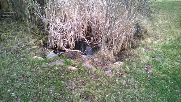
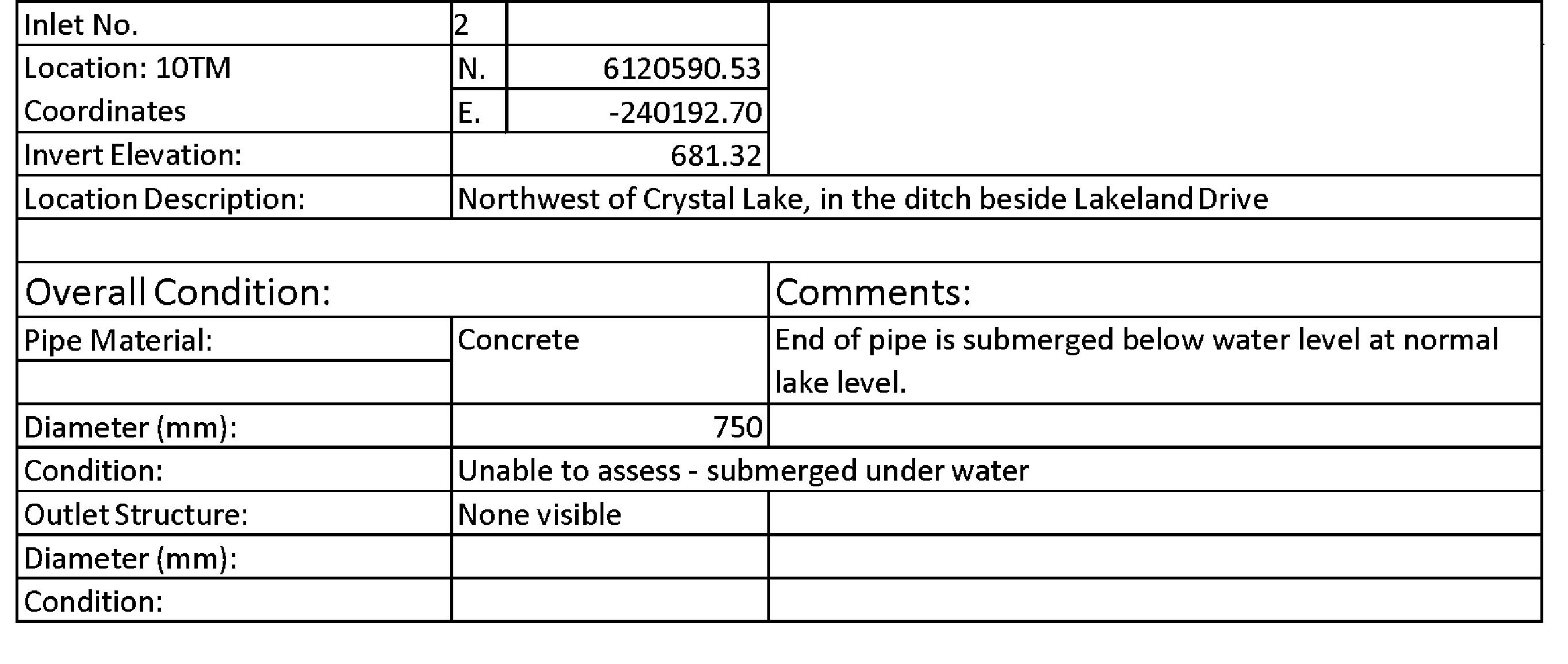
Crystal Lake – Inlet No. 2
Inlet No. 2 is a 750 mm concrete pipe located at the Northwest side of Crystal Lake, in the ditch beside Lakeland Drive. Its coordinates are N. 6120590.53 / E. -240192.70, based on a 10TM Coordinate System, and it has an invert elevation of 681.32 m. At the time of inspection, the end of the pipe was submerged below water level at the normal lake level. Due to this, ISL was unable to assess the pipe condition.


The location of Inlet No. 2 is heavily overgrown with vegetation, and contains significant amounts of detritus material suspended in the water. Remediation of this inlet will require removal of the vegetation in the area to expose the inlet to allow for proper drainage. In addition to this, any vegetation or material blocking the flow path to the inlet should be removed to ensure the storm pond is operating efficiently.
Crystal Lake – Inlet No. 3
Inlet No. 3 is a 250 mm PVC pipe located at the northwest side of Crystal Lake, approximately 56 m east of Lakeland Drive. Its coordinates are N. 6120556.50 / E. -240145.87, based on a 10TM Coordinate System, and it has an invert elevation of 682.09 m. This inlet structure is in good condition, and no outlet structure was recorded. It should be noted that As-Built drawings from 2001 showed only overland drainage in this area.
Though the inlet pipe of this structure is in good condition, the opening of the pipe has become partially blocked by the organic matter surrounding it. In addition to this, no riprap was observed during the field survey. The recommendations for remediating this inlet involve excavating around the pipe to fully expose the structure and remove any overgrown vegetation in the pipe inlet. Once the pipe is exposed, riprap should be applied to the area to prevent this issue from re-occurring.


Crystal Lake – Inlet No. 4
Inlet No. 4 is a 750 mm Ultra Flow pipe, with a thin PVC liner of approximate 675 mm diameter. The inlet is located at the northwest corner of Crystal Lake, at the end of a PUL lot south of 93A Street. Its coordinates are N. 6120446.84 / E. -239971.16, based on a 10TM coordinate system, and it has an invert elevation of 681.49 m. This structure also has a 750 mm concrete flared end outlet.


Both the inlet and outlet structure are in good condition, however the outlet has experienced some erosion around the top of structure. Additionally, the outlet has experienced joint separation. There is also an extensive overgrowth of vegetation in this area, which impedes the stormwater flow in the area. The recommendation for remediation at this inlet is to remove and reattach the flared concrete end outlet which has experienced joint separation while clearing the overgrown vegetation in the area. Additional fill and riprap is proposed on top of the reattached flared end outlet.
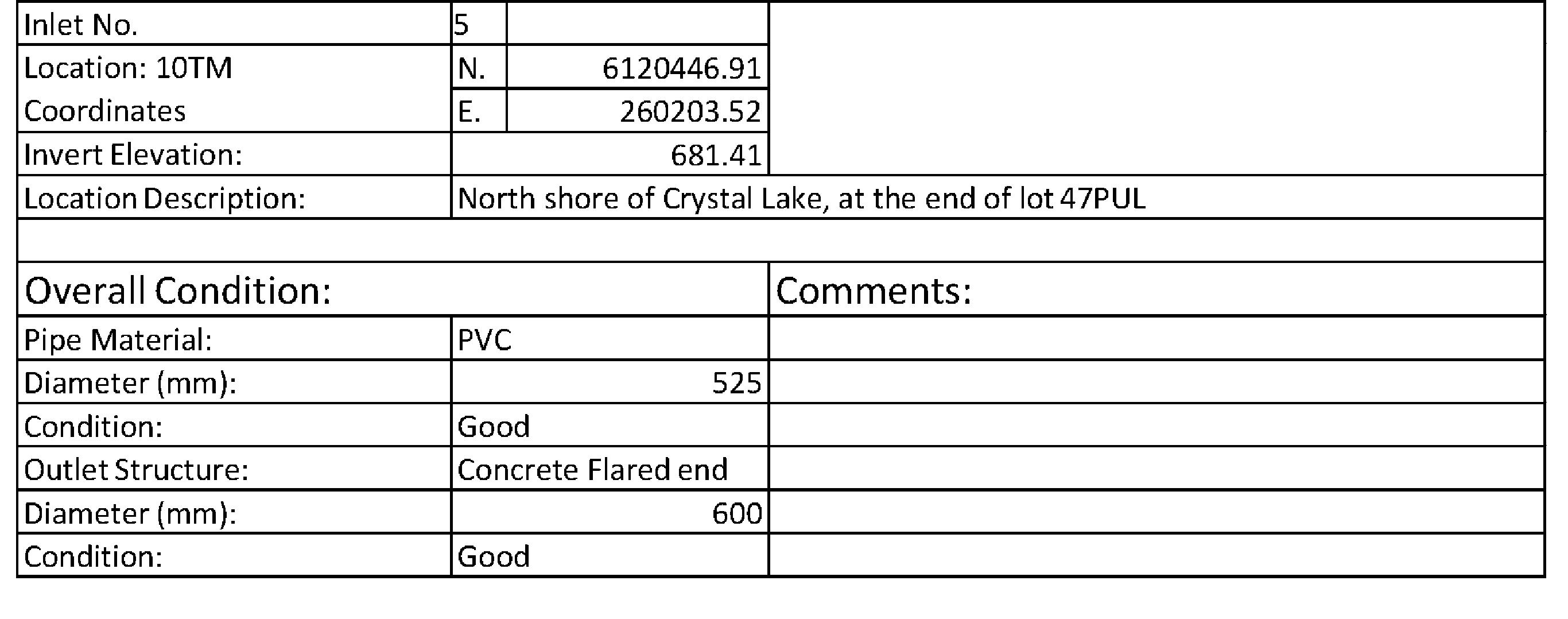
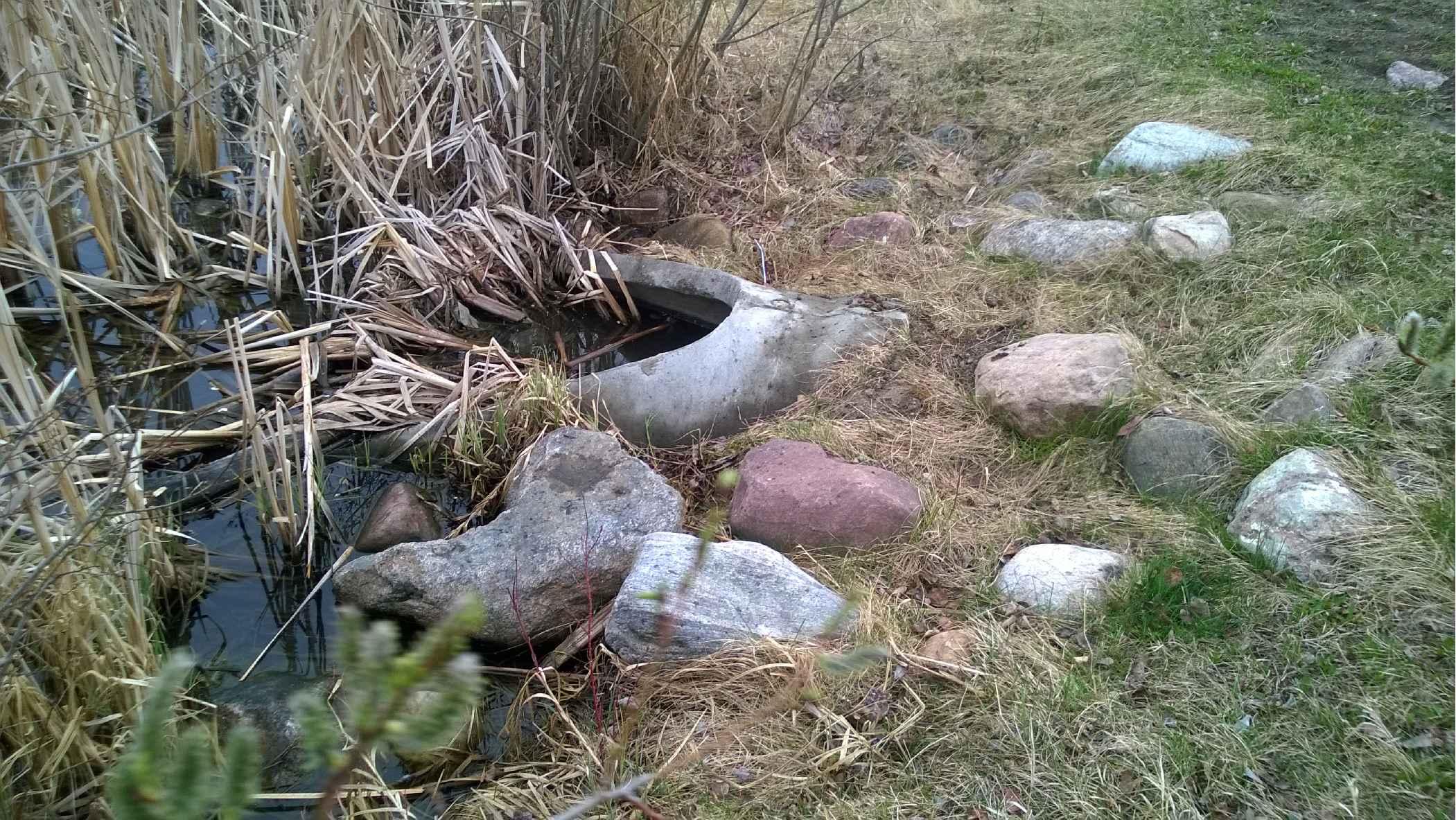
Crystal Lake – Inlet No. 5
Inlet No. 5 is a 525 mm PVC pipe, with a 600 mm concrete flared end outlet structure. The inlet is located on the north shore of Crystal Lake, at the end of PUL Lot 47. Its coordinates are N. 6120446.91 / E. 260203.52, based on a 10TM coordinate system, and it has an invert elevation of 681.41 m.

The inlet and outlet structures are in good condition in this area, but it should be noted that dirt has accumulated between the PVC pipe at the flared concrete outlet structure. The area surrounding the outlet also contains a large amount of plant debris. This debris should be removed to allow the water to flow properly from the outlet. An outlet channel may need to be chased into the lake to ensure a flow path is maintained.

Crystal Lake – Inlet No. 6
Inlet No. 6 is a 750 mm Ultra Flow pipe, with a 750 mm concrete flared end outlet structure. The inlet is located on the north shore of Crystal Lake, at the end of a PUL lot south of 91 Street. Its coordinates are N. 6120469.26 / E.239630.99, based on a 10TM coordinate system, and it has an invert elevation of 681.38 m.


Both the inlet and outlet structures are in good condition, however the area surrounding the outlet is overgrown. As a result, the outlet has also accumulated a significant amount of plant debris in its opening. This will reduce the hydraulic effectiveness of the structure, and impede the flow in the area. The vegetation in the area should be cleared, and the outlet structure should be removed of all debris to ensure an adequate flow path is present to the outlet.
Crystal Lake – Stormceptor Oil and Grit Separator
The Stormceptor (OGS) is located on the north shore of Crystal Lake, at the location of inlet 6 (N. 6120469 / E. 239630.99 based on a 10TM coordinate system). The invert elevation of the OGS (681.38 m) is lower than the NWL of Crystal Lake (681.75 m), thus the levels of oil and grit in the OGS weren’t able to be determined at the time of survey. Vegetation in this area is heavily overgrown, and is likely impacting the effectiveness of the OGS
Additionally, Crystal Lake Figure 5.0 highlights a sediment depth ranging from 0.20-0.30 m surrounding the OGS,
which is greater than the sediment levels in the surrounding areas. ISL recommends that vegetation and sediment should be cleared to ensure optimal operation of the structure.
Additionally, since it was determined upon investigation that the lake levels backup into the OGS, it is likely that more sediment is being accommodated by the OGS than originally accounted for in the design. Given this, it is likely that the OGS has substantial sediment accumulation, and is filling at a faster rate than normally anticipated.
The City should increase the frequency at which this OGS is hydrovaced in order to ensure the OGS is operating as designed. As this NWL is above the OGS invert elevation, it should be highlighted that water levels within the OGS during cleaning will not drop (Unless the outlet is plugged) Care should be taken to ensure excessive water volumes are not removed during cleaning to mitigate large maintenance costs.
Crystal Lake – Inlet No. 7
Inlet No. 7 is a 525 mm concrete pipe, with a 525 mm concrete flared end outlet structure. The inlet is located on the north shore of Crystal Lake, at the end of a PUL lot south of 90A Street. Its coordinates are N. 6120487.36 / E.239455.57, based on a 10TM coordinate system, and it has an invert elevation of 681.35 m. At the time of survey, the inlet structure was submerged under water, and its condition was unable to be assessed. The outlet structure is in good condition.

The area downstream of this inlet structure is heavily overgrown. This can cause the interruption of the flow into the storm pond. To remediate this inlet, these plants should be cleared to open the flow path into the lake and to prevent pooling of the water in the area around the inlet.
Crystal Lake – Inlet No. 8
Inlet No. 8 is a corrugated steel pipe, with a height of 625 mm and a width of 1425 mm. A concrete flared end outlet was associated with this structure. The inlet is located on the west shore of Crystal Lake, between 121 Avenue and 122 Avenue. Its coordinates are N. 6119957.45 / E. -240060.49, based on a 10TM coordinate system, and it has an invert elevation of 681.68 m. Both the inlet and the outlet structure were in good condition, with some minor erosion noted on the inlet.

As seen in the image below, the inlet structure contains a control structure to control the flow in the inlet. At this time, the sediment levels have not reached the spill elevation of the control structure, thus the function of the inlet is not compromised. The outlet is in good condition and currently requires no remediation. The City should periodically examine the vegetation in the area to ensure flow paths are not blocked by overgrowth.

Inlet structure partially blocked by sediment, and outlet in good condition.
Crystal Lake – Outlet No. 1
Outlet No. 1 is located in the northeast corner of Crystal Lake, at the end of the PUL lot at 127 Avenue. Its coordinates are N. 6120425.00 / E. -239324.44, based on a 10TM coordinate system, and it has an invert elevation of 681.75 m. The outlet structure was composed of two TK1 frames and grates, with side inlets. Each grate measured 430x630 mm. The outlet structure was in good condition, and the survey team noted that the grates were covered with debris. This structure was also made up of PVC pipe, which was unable to be measured or assessed by the survey team.
To ensure that this outlet structure is properly functioning, the City should ensure that the two grates be regularly maintained. The debris that accumulates on the structure should be removed as frequently as needed. In addition to this, the flow upstream of the outfall is impeded by the overgrowth of plants and the accumulation of sediment in the pond. The area upstream of the outlet should be cleared to create an uninterrupted flow path for the drainage system.


3.3 Ivy Lake
ISL was engaged to assess four (4) inlet structures which contribute to Ivy Lake. However at the time of each inspection, these structures were submerged in deep water and thus inaccessible. To obtain an idea of the condition of the inlet structures, ISL examine the manholes upstream each of the pipes. The location of each of these inlets along with their upstream manholes is illustrated on Ivy Lake Figure 4.0 along with the overland drainage route for the lake. The overland drainage route represents the area where the water will spillover in the event the pond’s capacity is reached. This portion of the report outlines the findings of this assessment. A summary of these findings can be found in Figures 7.9 through 7.12 following this report.
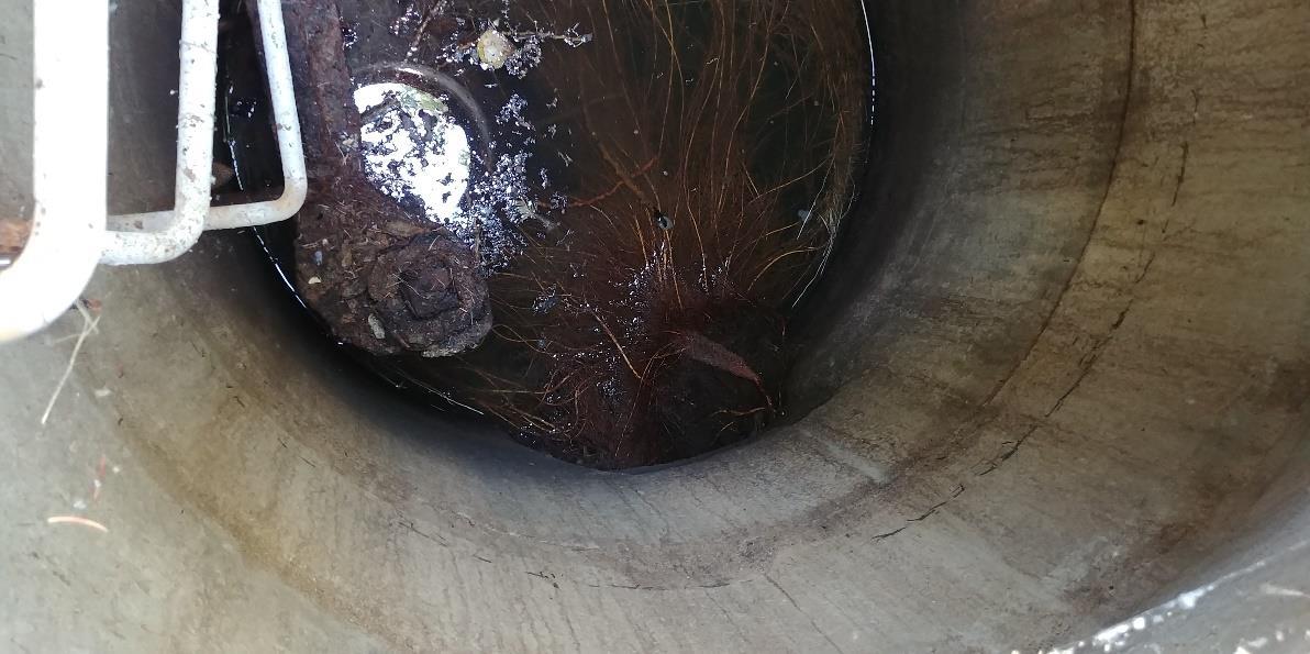
Ivy Lake – Manhole No. 1

Manhole No. 1 was a 1200 mm diameter grated-top catchbasin upstream of Inlet No. 1. Inlet No. 1 is located on the west-most corner of Ivy Lake, with the associated manhole located at N. 6117938.5/ E. -239590.35, based on a 10TM coordinate system. The rim elevation of the manhole was 660.3 m. The manhole was assessed to be in good condition with a water depth of 2.83 m, but contained a significant amount of sediment. The outlet for the structure was completely plugged due to the high sediment levels in the manhole.

Field survey observed that the outlet elevation from this manhole is below the elevation of sediment in the manhole. The outlet pipe was observed to be completely blocked by sediment. Considering this, it would suggest the Inlet No. 1 to Ivy Lake is not functioning efficiently due to the amount of sediment in the pipe. ISL recommends dredging the sediment from this manhole and flushing the pipe leading to Inlet No. 1 to ensure unimpeded flow through this inlet.
Ivy Lake – Manhole No. 2
Manhole No. 2 was a 900 mm diameter grated-top catchbasin upstream of Inlet No. 2. Inlet No. 2 is located on the southwest shore of Ivy Lake, with the associated manhole located at N. 6117806.77/ E. -239501.51, based on a 10TM coordinate system. The rim elevation of the manhole was 658.59 m. The manhole was assessed to be in good condition with a water depth of 1.07 m, but contained a heavy sediment. The outlet for the structure was submerged in deep water.

The outlet to this manhole doesn’t appear to be blocked, and is observed to be functioning properly. The standing water observed in this manhole indicates that the NWL of the lake (657.65 m) is higher than the pipe crown. No vegetation or sediment is impacting the flow in this structure, and thus it is assumed that Inlet No. 2 to Ivy Lake is also functioning adequately. Sediment levels in the manhole should be monitored to ensure no blockage of the outlet occurs.

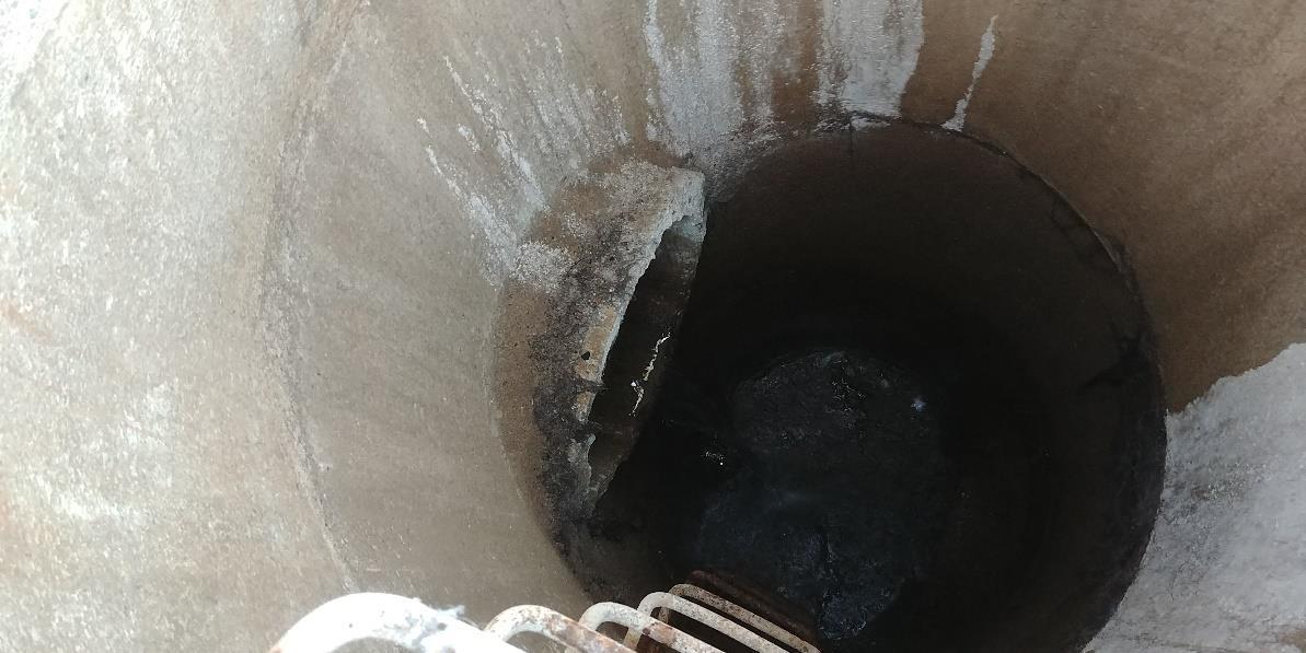
Ivy Lake – Manhole No. 3
Manhole No. 3 was a 1200 mm diameter storm manhole upstream of Inlet No. 3. Inlet No. 3 is located on the southeast shore of Ivy Lake, with the associated manhole located at N. 6117814.23/ E. -239149.8, based on a 10TM coordinate system. The rim elevation of the manhole was 659.63 m. The manhole was assessed to be in good condition with cracked rings noted. The water depth in the manhole was approximated to be 2.3 m, and a steady flow was noted into the pipe. This steady flow was also low compared to the pipe diameter. The outlet for the structure was heavily blocked with vegetation as can be seen in the photo below.
Given the significant amount of vegetation observed in the manhole, the flow in the outlet pipe towards Inlet No. 3 to Ivy Lake is assumed to be heavily impeded. In order to ensure adequate flow in the system, ISL recommends removing the vegetation from the outlet pipe, and to clear vegetation surrounding the inlet in Ivy Lake. Any sedimentation blocking the outlet should also be removed to improve the flow path.
Manhole No. 4 was a 1200 mm diameter storm manhole upstream of Inlet No. 4. Inlet No. 4 is located on the north-most corner of Ivy Lake, with the associated manhole located at N. 6118136.59/ E. -239256.51, based on a 10TM coordinate system. The rim elevation of the manhole was 659.84 m. The manhole was assessed to be in good condition with a water depth of 2.4 m A significant amount of sediment was noted in the bottom of the manhole.
This manhole currently appears to be functioning properly. The sediment levels should be monitored periodically to ensure no blockage of the outlet occurs.


4.0 Recommendations and Summary of Findings
4.1 Recommendations
A full summary of the remediation actions to be taken are as follows:
Overall Sediment Removal:
Sediment removal in Crystal Lake within the next year
Additional survey of Ivy Lake within the next 5 years
Crystal Lake:
Inlet No. 1 and the associated outlet should be maintained to avoid vegetation overgrowth. The lid of Inlet No.1 should be properly affixed with a new lock.
The area surrounding Inlet No. 2 should be cleared of overgrown vegetation to ensure clear flow paths
The area around Inlet No. 3 should be excavated and vegetation should be removed to fully expose the pipe. Riprap should be applied around the structure.
The joint-separated outlet associated with Inlet No. 4 should be removed and reattached. Riprap should be placed around the reattached outlet structure. Overgrown vegetation should be removed around the inlet and outlet.
The debris around Inlet No. 5 should be removed. An outlet channel may need to be chased into the lake here to ensure a flow path is maintained.
The overgrown vegetation should be cleared from Inlet No. 6 and associated outlet.
Overgrown vegetation and sediment surrounding the Stormceptor should be cleared. The hydrovacing frequency of the stormceptor should be increased to ensure the OGS is operating as designed
Overgrown vegetation should be cleared from Inlet No. 7.
The sediment blocking Inlet No. 8 should be removed and riprap should be placed around the structure to prevent further blockages.
The two grates making up the Outlet No. 1 structure should be regularly maintained to remove any debris buildup. The upstream flow path should also be cleared of vegetation.
Ivy Lake:
Sediment should be removed from Manhole No. 1 and its outlet pipe. The pipe should also be flushed to ensure no blockage of Inlet No. 1 is occurring.
The vegetation noted in Manhole No. 3 should be removed from the outlet pipe. Any vegetation in Ivy Lake surrounding Inlet No. 3 should also be removed.
Sediment levels in all manholes should be monitored periodically to ensure no blockage of the outlets is occurring.
The emergency spillway as surveyed is not consistent with the City’s historical data. While this appears to be causing no downstream impacts, the town’s records should be updated for future development considerations.
4.2 Summary
ISL completed high water and bathymetric surveys of both Crystal Lake and Ivy Lake. Currently, the survey in Crystal Lake confirmed that sediments remain below the NWL. In the western portion of Crystal Lake, sediments are very near the NWL, indicated that the City should plan for removal in the next year. ISL also surveyed a total of eight inlets and one outlet around Crystal Lake, and four manholes around Ivy Lake. All of the structures around Crystal Lake were in good condition, with only minor erosion and joint separation noted on the concrete flared end outlet associated with Inlet No. 4 and minor erosion associated with Inlet No. 8. A common issue noted at all the structures was the overgrowth of vegetation, significant debris and an accumulation of sediment surrounding the inlets and outlets. This reduced the effectiveness of the stormwater management facilities as water was prevented from flowing directly into or out of the pond. Additionally, it was determined upon investigation that the lake levels backup into the OGS. Given this, it is likely that the OGS has substantial sediment accumulation, and is filling at a faster rate than normally anticipated. The City should increase the frequency at which this OGS is hydrovaced in order to ensure the OGS is operating as designed.
The high water bathymetric survey of Ivy Lake indicated that the sediments remain adequately below the NWL, suggesting that no sediment removal is required at this time. Given this, Ivy Lake should be surveyed again within five years to determine any future clean-up requirements. Additionally, ISL indirectly assessed the conditions in Ivy Lake’s four inlet structures through examining the upstream manholes of each of the inlets. This was done due to the high water levels in the lake at the time of survey, causing the inlets to be inaccessible. All manhole structures were noted to be in good condition, with only Manhole No. 3 displaying cracked rings. Heavy sediment was noted in all structures, with the outlet in Manhole No. 1 being completely blocked by the buildup. The outlet in Manhole No. 3 also experienced partial blockage by vegetation in the pipe.
The above recommendations should be implemented to ensure both storm facilities are functioning adequately to service the community.
TOPOFSEDIMENTATION
TOPOFSEDIMENTATION


Equipment Calibration Methods

Equipment Calibration Methods
City of Grande Prairie – Ivy and Crystal Lake Bathymetry and Assessments
1.0 Equipment Used
Trimble R10 GNSS Receiver – Base
Serial Number # 5334442043
Trimble R6 GNSS Receiver - Rover
Serial Number # 5417463162
Seafloor Systems Echo Boat
Serial Number # N/A
Seafloor Systems SonarMite
Serial Number # SMIL250413
1.1 Calibration Methods:
GNSS Receivers
The only calibration required is to localize the survey to the Alberta Survey Control Monument (ASCM) system in the City of Grande Prairie. This is completed by measuring each ASCM for a total of 180 epochs (1 second epochs) and then preforming a horizontal and vertical transformation to published coordinates that were obtained through Spin2 (Alberta Land Titles Spatial Information System). Each GNSS receiver requires no physical calibration.
Echo Boat
The Echo Boats online navigation system must be calibrated every time the boat is moved more than 300km from where is lasted preformed its work. Seafloor Systems AutoNav Control System must have its compass calibrated, which is done by following simple steps that involve the rotation of the system on all rotational axis. The program records and makes necessary adjusts to the system. If it notices that the changes are beyond those specified, it will ask to have the calibration preformed again. ISL completed a calibration on the day of survey, which met specified standards.
SonarMite
The SonarMite requires it’s velocity of sound to be set by taking a temperature reading at mid column of the waterbody and adjusting the profile within the unit. In the case of this survey ISL measured a water temperature of 9 degrees Celsius, which correlates a speed of sound of 1443.23 m/s. This was observed in both lakes. ISL preformed physical measurement checks to a fix length plate, as well as repeatable sonar measurements to the same point.