Recreat iona l Outboard Service Manual 2 thru
V-6 Models
Section 1 - General Information
of Contents
After Storing - Before Using 1-56
Arrangement of Service Manual 1-6
Break - In ..... ....

1-47
Carburetor Orifice Plug Reference Chart 1-51
Checking Propeller Hub Slippage - 4 Deluxe thru 30 1-50
Dr i ll Size Conversion Chart 1-53 Engine Fuel and Lubricant . . .......... ... 1-44
Gearcase Lubrication - 2 1-25
Gearcase Lubrication - 4 thru V-6 1-25
General Specifications 1-24 Good Service Practice 1-6 Heli-Coil ® Inserts and Installers 1-60 I ntroduction 1-6 Lubrication 1-24
Lubrication Chart - 2 and 4 . 1-26
Lubrication Chart - 4 Deluxe, 4 5, 5, 6 and 8 . ...
. ......... . 1-28
Lubrication Chart - 9.9 and 15 . . . 1-30
Lubrication Chart - 20, 25 and 30 ... . . . ... 1-32
Lubrication Chart - 40, 50 and 60 (Remote Control Models) 1-34
Lubrication Chart - 40 Rope, 45CR and 55CR . 1-36
Lubrication Chart - 70 and 75 1-38
Lu brication Chart - 90, 115 and V -6 1-40
Lu brication Chart - 120 and 140 1-42
New Motor Preparation . ......... . . ..... 1-62
Off-Season Storage ..................... 1-54
Outooard Models Covered in This Service Manual 1-2 , 1-3, 1-4
Outboard Motor Nomenclature . 1-8
Parts Catalog 1-7

Trim and Tilt Reservoir
Remote Control Warning Test (At Control) ' -57
Parts and Product Reference '-7
Policy
Service Tools .......
1-7 Spec ifica tions - 2 and 4 1-1 1-11 Sp ec ifications - 4 Deluxe thru 8 1-12,1 - 13
Spe c ifications -9 9 and 15 1-14,1-15 Specifications - 20 thru 30 ,. 1-16,1 - 17
Specifications - 40 thru 75 1-18, 1-19
Specifications - 90, 115 and V-6 1-20, 1-21
Specifications - 120 and 140 1-22, 1-23
Steering System Lubrication - Remote lectric Models 1-25
Submerged Motors 1-58
Synchronization and Linkage Adjustments2 thru 15 Models 1-64
Synchronization and Linkage Adjustments20 thru 30 Models . .. . . .. ..... . ... . ... 1-68
Synchronization and Linkage Adjustments40 and 50R and Models 1-70
Synchronization and Linkage Adjustmentsthru V6 (Except 120, 140 Models) 1-74
Synchronization and Linkage Adjustments120 and 140 Models 1-82
Testing Anti-Corrosion Anodes - AII Models .. 1-47
TroubIe Check Chart 1-88' 1-89, 1-90
Tune-Up Procedure 1-61
Weather, Altitude and Engine Performance " ' -63
. .
. . .
......
. ... .....
.
... .. .. .
.
..
..
Part
1-24 Propeller
1-48
Selecting
..... . .....
Service
Special
.
. . . .
Power
Selection
Replacement
Propeller . . . . . .. . .
1-49
.
......
.
E4BRLCO

E4RDCO
E4RDLCO
Outboard Models Covered in This Service Manual
2 thru V-6 Models
25 Models
J25RCO J25TECO
E25RLCO E25TELCO J25RLCO J25TELCO
J25BACO J25ECO
E25BALCO E25ELCO J25BALCO J25ELCO
30 Models
J30RCO J30BACO
E30RLCO E30BALCO J30RLCO J30BALCO J30ECO J30TECO
E30ELCO E30TELCO J30ELCO J30TELCO
40 Models
J40RCO J40ECO
E40RLCO E40ELCO J40RLCO J40ELCO J40BACO J40TECO
E40BALCO E40TELCO J40BALCO J40TELCO
50 Models
E50TELCO J50BECO J50TELCO
E50BELCO E50TLCO J50BELCO J50TLCO
60 Models

J60ECO
E60ELCO J60ELCO E60TLCO J60TLCO
70 Models
E70ELCO J70ELCO E70TLCO J70TLCO
75 Models
E75ELCO J75ELCO J75ECO E75TLCO J75TLCO
• • •
1-3
2 thru Models
90 Models

E90MLCO
E90TLCO
E115MLCO
E115TLCO
E120TLCO
E140TLCO
E150STLCO
E150TLCO
E150ANCO
E175TLCO
E185TLCO
E235TLCO
E235STLCO
J90MLCO
J90TLCO
J90TXCO
115 Models
J115MLCO
J115TLCO
120 Models
J120TLCO
J120TXCO
140 Models
J140TLCO
J140TXCO
Models
J150TLCO
J150TXCO
J150STLCO
J175TLCO
J175TXCO
J185TLCO
J185TXCO
J235TLCO
J235TXCO
J235STLCO
This Service
• •
Outboard Models Covered in
Manual
1-4 •
2-V6
Introduction
This manual covers Service 1nformation current models 2 thru V-6. Much of the information also applies to previous models.
Use this manual together with the Parts Catalog for part numbers and for exploded views which valuabIe aid to disassembIy and reassembIy.
This manual presents the metric dimension first and the English dimension in parentheses ( ). When referring to the metric dimension, is used to represent decimal point which is standard printing practice in Europe.
Good Service Practice
When repairing component, the most reliabIe way to assure good job is to do complete overhaul that component, rather than just replacing the bad part. Wear not readily apparent other parts could cause malfunction soon after the repair job. Repair kits and overhau 1 kits contain the parts needed to assure complete repair, to eliminate guesswork, and to save time. Repair time also minimized the use of special tools. special tools speed repair work so it done within flat rate time. 1n some cases the use of substitute tools actually damage the part.
•

• prevent possibIe injury always wear SAFETY GLASSES while servicing motor. When testing adjusting running engine with the motor cover removed: keep hands, hair, and clothing away from rotating flywheel do not touch electrical system parts. Reaction to electrical shock could result in contact with rotating flywheel.
• Refer to solvent manufacturer's caution regarding use and storage of solvent.
fN=t;1 00 not operate motor out of water even momentarily. If operated in test tank use test wheel. Failure to do so result in damage to water pump and motor overheating.
Arrangement of Service Manual
This Service Manual includes the specific information you will need to service Outboards. general procedures covered in abbreviated form mostly reference to procedural illustrations. The specific procedures wh ich apply only, primarily, to each motor covered in fully-illustrated, detailed, step-by-step instructions as required.
The General Service Information section will help you diagnose malfunctioning outboard. It includes specifications and lubrication procedures. Clearances and torque values also included for quick reference during servicing operations. Each of the following sections, Fuel System, Ignition System, Powerhead, Mid-Section, Gearcase, Manual Starter, Electrical System, Tilt, gives detailed instrucreassembIy, and operating procedures will help you completely overhaul the models.
1-6 2 V6
Outboard Motor Nomenclature
Sometimes the words "right" and "Ieft" very confusing when referring to the sides of outboard motor. Therefore, the sides referrea to as STARBOARD PORT sides. STARBOARD means the right hand while facing the bow (F of the boat; PORT means left hand.
Service required for motors is generally of three kinds
1. Normal and Maintenance - which includes putting new motor into operation, storing motors, lubrication, and under special operating conditions such as salt water and cold weather.
2. Operating Malfunctions - due to improper motor mounting, propeller condition size, boat condition, the malfunction of some of the motor. This includes motor tune·up procedures to keep the motor in prime operating condition.
3. Complete DisassembIy and Overhaul - such as inspecting motor that has submerged, rebuilding trade·in units.
It is important to you as the service person to determine before disassembIy just what the troubIe is, and how to correct it quickly and with minimum expense to the owner.

1·8 2 V6
determine size for oversize pistons, add oversize dimension to standard size
Ignit ion Syste m

Specifica ti o ns - 2 a nd 4 G eneral 2 4 Full Throttle Operating Range ........• 4000 5000 .• • 4500·5500 Idle in Forward Gear with Propelle r 650 600 Test Wheel and No. 316021 Part No. 317738 (4 -9/16" dia 5/8" wide) ' (5 -1/4" dia. 11/16" wide) 3900 4550 Pow e rhead and Stroke • 39 ,8 34,9 39,7 34,9 (1.567" 1.374 " Stroke) (1 565 " 1 374" Stroke) Piston Displacement ..•.. 43 (2 64 in.) 87 (5.28 in.) Crankshaft Size Journal ..........•... 19,055 - 19.042 (0.7502" - 0.7497") 19 ,075 - 19,063 (0 751 - 0 7506") Center Journal .......• ......• 16,993 - 16,980 (0 6690 " - 0.6685") Bottom Journal 19,055 - 19,042 (0.7502" - 0.7497") 19,055 - 19.045 (0 7502" - 0 7498 " ) Connecting Rod Crank Pin .•. • 17,018 - 17,005 (0 6700" - 0.6695") 17 ,018 - 17,005 (0 6700 " - 0 6695") +Standard Size 39,815 - 39,797 (1 5675" - 1 5668") 39,751 - 39 ,733 (1.5650" - 1 5643") +
Ignition .•.... • • Flywheel magneto ...• Flywheel magneto Spark Plug Champion • •. ..•.•...... RJ6C J6C - 14 RL86C L86C - 14 Spark Plug Gap .....• 0,76 (0.030 " ) 0 ,76 (0 030 " ) Breaker Point Gap 0'51 (0 020") 0,51 (0.020 " ) Condenser No 580321 - 0.18 - 0 22 Mfd No 580321 - 0 18 - 0 22 Mfd Ignition Coil •..... • No 582995 • No 582995
No 582995
Tester
ST-75 Normal Polarity (Switch Setting Standard) Stevens Tester Model No - 75 80 1.8 Switch I ndex Adjustment 26 Primary Secondary Secondary Operating Resistance Continuity Resistance Amperage Min Min Min. 1 3 0.7 1 1 50 60 6500 9000 Graham Tester Model 51 Maximum Maximum Coil Minimum Gap Secondary Primary Index Coil Test Index 10.000 1.4 60 25 60 Coil Ohmmeter Test Primary (Low Ohms) ........• • ..• 0 9!1 ± 0.2 Secondary igh Ohms) •. .•. ...• 8000 !1 ± 300 1-1 2 -V6
Ignition C oil T est Specific a tions
Stevens
Model
Fuel System

Clearance Chart Powerhead
Torque Chart
2 4
Carburet i on ...•.. Single barrel float feed, with high and Single barrel float feed, fixed high low speed adjustments, manual choke speed adjustabIe low speed, manual choke Float Level Setting Between steps gauge Part No. 324891 Between steps gauge part No 324891 Float Setting 28 38 (1 125"·1 500") 28 38 (1.125" 1 500")
Piston Ring End Gap ..•. 0,64· 0 ,38 (0 025" · 0.015") 0,38· 0,13 (0 015" ·0 005 " ) Pi ston Ring Groove Side Clearance .•..•... 0 , 10 (0.004" 0 , 10 (0 004"
Powerhead Flywheel Nut 30·34 N ' m (20·25 ft.lbs ) 40 54 N ' m (30 40 ft lbs ) Connecting Rod Screws •. 7'0·7' 5 N'm (60·66 in.lbs.) • 7 ' 0 7'5 N ' m (60 66 in lbs ) Cylinder Head Screws ..• ..• •. 7 ,0 9,0 N ' m (60 80 in Ibs ) 7 ,0 9.0 N ' m (60 80 in Ibs ) Crankcase to Main Bearing Screws Upper, Center, Lower ..•... 7,0 9.0 N ' m (60 80 in Ibs ) Bearing Housing to Cylinder Screws 7,0·9.0 N ' m (60 80 in Ibs ) Spark Plug •.... 24·27 N'm (18·21 ft. Ibs.) 24 27 N'm (18 21 ft lbs.) Gearcase Mounting Screws 7 9 N ' m (60 80 in. Ibs.) 7·9 N'm (60·80 in.lbs.) 1-11 2 V6 Rec
Powerhead

Deluxe thru 8 General 4 Oel u xe alld 4.5 5,6 and Full Throttle Operating Range 4500 · 5500 ..• ...•... 5 and 6 - 4500 5500 - 5000 6000 Idle in Forward Gear with Propeller 600 • 650 Test Wheel and •. No. 390123 • • .•. No 390239 (5 3/4" dia wide) (5 3/4" dia 1·1 / 8" wide) 5100 4900
Specifications -4
and Stroke • 39,69 34,93 49 ,21 mm 43,18 (1 5625" 1 375 " Stroke) (1 9375 " 1 700" Stroke) Piston Oisplacement .• 87 cu. in ) 164 (10 0 cu in ) Crankshah Size Journal ...• 19,075· 19,063 (0.751 0 7505") 22,282·22, 155 mm (0.87725" 0.87225") Center Journal • 16,993 16,980 (0.6690" 0 6685") 20,712 20,585 (0.81545" ·0 8104") Journal • • 19.055·19,045 (0 7502" 0 7498") 19 ,207·19 ,045 mm (0 7562" ·0 7498") Connecting Rod Crank Pin 17,018· 17,005 (0 6700 " 0.6695") 17,018· 17,005 mm (0 6700 " 0.6695") +Standard Size 39'751·39,733 mm (1.5650" 1 5643 " ) 49'225 49 ' 207 mm (1 9380" 1.9373") + determine
for
pistons, add oversiz e dimension to standard size Ignition
Ignition Flywh ee l magn eto , breakerless , Flywh eel magneto breakerless Spark Plug (Champion) Sust ained Low Speed Operation GL77J4 ....•. • GL77J4 Alternate L77J4 L77J4 Gap Setting 1,0 (0 040") 1 0 mm (0 040") Sustained High Speed Operation .•.... ....• .•..... GL78v • GL78V Alternate L78V •. ..•.. L78V Gap Setting Gap Is • •. Gap Is Ignition Coil No 582508 No 582508 RPM Limiter Powerpack .•. •...... 8 6200 Electrical System Alt ernator 5ystem Electric 5tart 4 amp flywheel Manual Start Model) .• 60 watt 12 V 60 watt at 12 V Ignition
Test Specifications - Part No. 582508 Stevens Model Merc O Tronic 9800 98 with Adapter Model 55 -980 imum Operating Amperage (Rever se Polarity · Switch Setting : 1 1 Amp s Ma x imum Oper ating Amperage (R ev erse Polarity) 1.5 Amp s Stevens Tester Model Primary Resistance • 0 1 Second ary Continu ity 5 Switch (U se Model Adapter - Rever se Polari t y) Inde
20 Igni t io ll Tests - 4 Deluxe thru Resistance Ground Test Cranking Output Meter Setting Reading Meter 5etting Reading Meter 5etting Reading Charge coil igh ohms scale 575 ± 25 High ohms scale 00 230 Sensor coil Low ohms scale 40 ± Low ohms scale 00 5,5 2 0 200 050 1-12 2 -V6
size
oversize
System
Coil
x Adjustment
Fuel System

Clearance Chart
Torque Chart
Powerhead
Gearcase
Mounting Screws
4 Delu xe ar1d 4 5 5,6 and 8
Carburetion .....•. Single barrel, float feed, Single float feed, fixed high speed adjustabIe fixed high speed adjustabIe low speed, manual choke low speed, manual choke Float Level Setting Between steps gauge Part No 324891 Between steps gauge No 324891 Float Setting 28 32 (1 125" - 1.500") 28 - 32 (1 125" - 1 500")
Piston Ring End Gap .........•..• ...•... 0,38 - 0 , 127 (0 015" 0.005 " ) 0 ,38 · 0,127 (0.015 " · 0 005") Piston Ring Groove Side Clearance 0 , 10 (0 004" 0,10 (0 004"
Flywheel Nut , , 40 - 54 N ' m (30 - 40 ft Ibs ) 54 - 67 N'm (40 - 50 ft Ibs.) Connecting Rod Screws 7.0 - 8,0 N ' m (60 - 66 in lbs ) 7 ' 0 - 8,0 N'm (60 - 66 in lb s. ) Cylinder Head Screw s • .•. 7,0 - 9,0 N ' m (60 - 80 in lbs.) ..•.. 16,0 - 19,0 N'm (12 - 14 ft Ibs ) Crankcase to Main Bearing Screws Upper, Center, Lower 7'0 - 9,0 N ' m (60 - 80 in. Ibs ) 16,0 - 19,0 N'm (12 - 14 ft Ibs ) Spark Plugs 24 27 N ' m (18 21 ft lbs.) • 24 - 27 N ' m (18 - 21 ft lbs ) Power Pack Mounting Screws _ _ _ 7 - 9 N m (60 - 84 in. Ibs ) 7 - 9 N m (60 - 84 in Ibs ) Ignition Coil Mounting Screws 7 - 9 N m (60 - 84 in Ibs ) 7 9 N m - 84 in. Ibs )
Front Screws • 14 - N ' m (10 - 12 ft lbs.) 14 N ' m (10 - 12 ft.lbs ) Screws ' ' 7 -9 N ' m - 80 in. Ibs.) • 7 - 9 N'm - 80 in. Ibs ) 1-13 2 -V6
Gearcase
determine correct size for oversize pistons, add over size dimen sion to standard
Ignition System
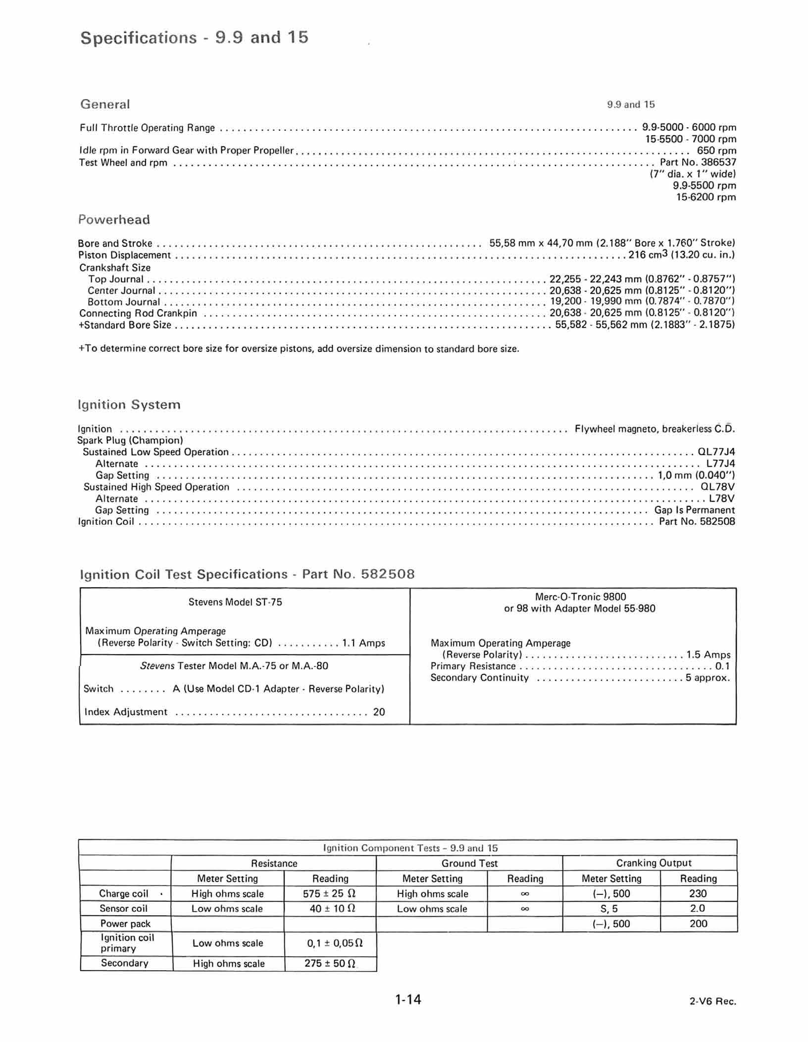
Specifications - 9.9 and 15 General 9 9 and 15 Full Throttle Operating Range .•............. •. •.. 9.9 5000 - 6000 15·5500 7000 Idl e in Forward Gear with Propeller .•........ • ....•......... •.. • .•... 650 Test Wheel and ...•...... : • ...• Part No. 386537 Powerhead (7" dia. 1" wide) 9 9-5500 15-6200 and 5troke ....• .•... ........•... 55 , 58 44,70 (2.188 " 1 760 " 5troke) Piston Oisplacement 216 (13 20 cu in ) Crankshaft 5ize Journal ...• • 22,255 22,243 (0.8762" -0.8757") Center Journal • • ...•......•. 20,638-20,625 (0.8125" - 0 8120") Bottom Journal ........•....... 19,200 - 19,990 (0 7874" - 0.7870") Connecting Rod Crankpin •.. 20,638 - 20,625 (0 8125 "- 0.8120 ") +5tandard Size 55 ,582 - 55,562 (2 1883" 2.1875) +
size.
Ignition Flywheel magneto, breakeriess Spark Plug (Champion) Sustained Low Speed Operatio n ....•....•......•............................ .•....•.......... OL77J4 Alternate L77J4 Gap Setting ..•... 1,0 (0 040") Sustained High Speed Operation ...•................•....•...... ...•........... ....•... OL78V Alternate ...•........ ........•.....................•.................... L78V Gap Setting Gap Is Ignition Coil Part No. 582508
Test Specifications -
582508 Stevens Model ST 75 Merc O Tronic 9800 98 with Adapter Model 55 980 Maximum Operating Amperage (Reverse Polarity Switch Setting : 1 1 Amps imum Operating Amperage (Rev erse Pol arity) 1 5 Amps S tev ens Tester Model Primary Resist ance 0.1 Secondary Continuity 5 Switch \Use Mod el Adapter · Rever se Pol arity) Inde x
20 Ignition Tests - 9 9 15 Resistance Ground Test Cranking Output Meter 5etting Reading Meter Setting Reading Meter Setting Reading Charge coil High ohms scale 575 ± 25 n High ohms scale 00 230 Sensor coil Low ohms scale 40 ± 10 n Low ohms scale 00 5,5 2 0 200 1-14 2-V6
Ignition Coil
Part No.
Adjustment
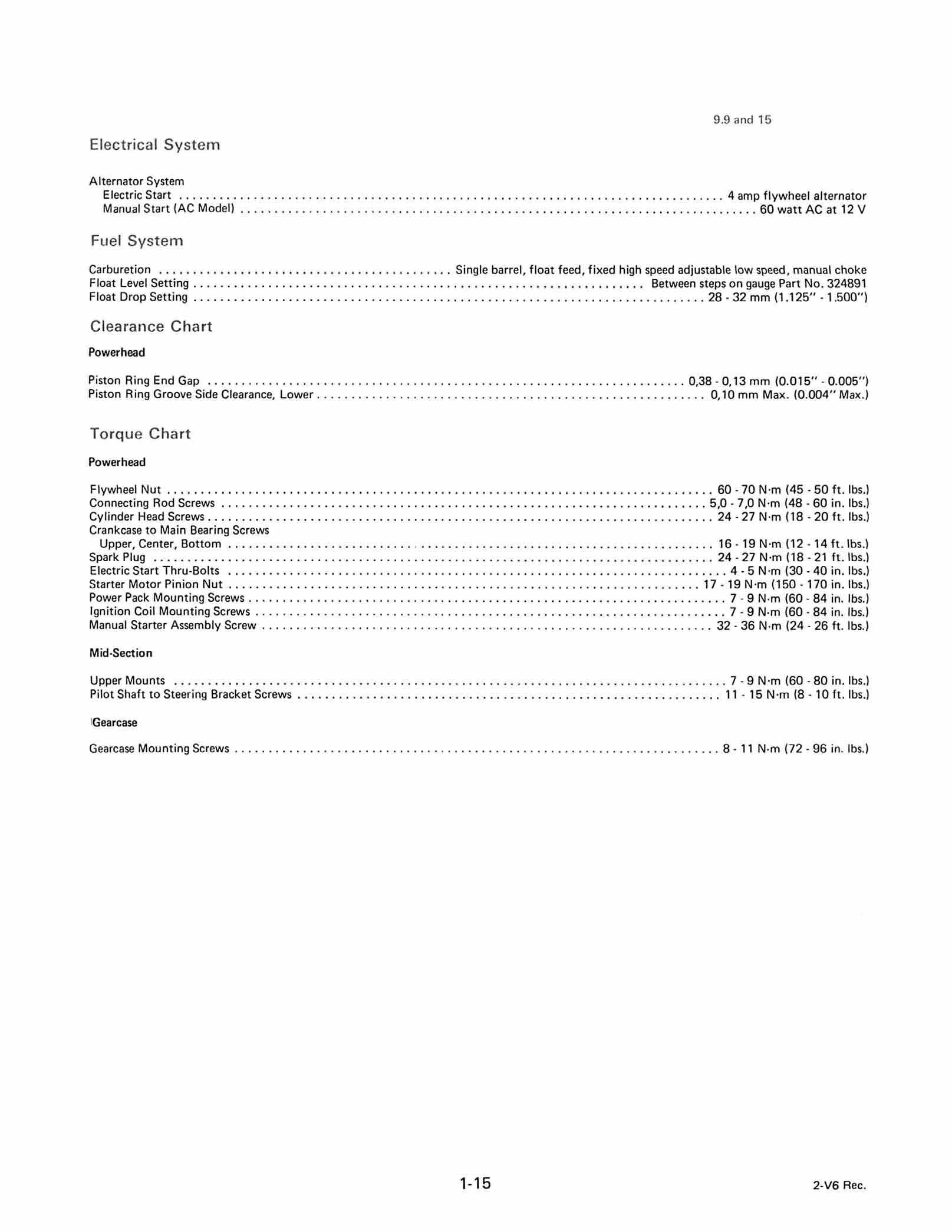
9.9and15 Electrica l S y stem Alternator System Electric Start •... •... ..• 4 flywheel Start Model) •.. .• .•. 60 watt at 12 V
Single barrel, float feed, fixed high speed adjustabIe low speed, choke Float Level Setting • • Between steps gauge Part No. 324891 Float Setting ..• • .•.... 28·32 (1.125" 1 500")
r t Powerhead Piston Ring End Gap 0,38 - 0 , 13 (0 015" - 0.005 " ) Piston Ring Groove Side Clearance, Lower • 0,10 (0.004" T orq ue Chart Powerhead Flywheel Nut •....... _ _ • _ _ 60 - 70 N ' m (45 - 50 ft. Ibs.) Connecting Rod Screws .• _ _ _ _ __ _ •. _ 5,0 - 7,0 N'm (48 - 60 in. Ibs ) Cylinder Head Screws _ _ • _ _ .• _ _ ..• • _ _ ___ • _ • _ _ 24·27 N ' m (18 - 20 ft. Ibs ) Crankcase to Main Bearing Screws Upper, Center, Bottom _ ___ • _ _ _ 16 - 19 N'm (12 - 14 ft.lbs.) Spark Plug _ ..• • _ _ _ • _ _ __ _ _ _ 24 - 27 N -m (18 - 21 ft. Ibs.) Electric Start Thru-Bolts • • 4 - 5 N -m (30 - 40 in Ibs.) Starter Motor Pinion Nut • • _ _ _ _ __ _ 17 -19 N -m (150 -170 in.lbs.) Power Pack Mounting Screws • _ _ _ _ 7 - 9 N -m (60 - 84 in. Ibs ) Ignition Coil Mounting Screws • ....• •. 7 - 9 N m (60 - 84 in Ibs ) AssembIy Screw • .• _ _ •.• ..•.. 32 - 36 N m (24 - 26 ft Ibs ) Mid·Section Upper Mounts ....•.. ...•..• _ • •... 7 - 9 N ' m (60 - 80 in Ibs.) Pilot Shaft to Steering Bracket Screws ..•.. • •.. • •.... 11 - 15 N ' m (8 . 1 ft Ibs.) IGearcase Gearcase Mounting Screws _ • • • __ _ _ 8 - 11 N·m (72 - 96 in Ibs ) 1-15 2-V6
Fuel System
Cl earance Ch a
determine size for overs i ze pistons, add oversize dimension to standard size.
System

Specifications - 20 thru General 20 thru 30 Full Throttle Operating Range ............•.. .•... .• 4500 5500 Idl e in Fo!Ward Gear with Propell er .•.... .•... .• 650 Test Wheel and .•...... • 20 - No 386891 Powerhead 25 and 30 - No 394145 20 - 4550 min 25 4800 min 30 - 5400 min. and Stroke 76.20 57 , 15 (3 000" 2 250 " Stroke) Piston Displacement ...•. .•.... 521 (31 8 cu. in.) Crankshaft Size Journal 31 , 775·31,788 (1 2510" 1 2515") Center Journal ....•..•. 30,056·30,069 (] .1833" 1.1838") Bottom Journal • •... ..•.... •. •. • 24,999 25,009 (0 9842" 0 9846") Connecting Rod Crankpin .•. • 30,043 30,030 (1 1828" 1.1823") + Standard Size 76,213 · 76,187 (3.0005" 2 9995 " ) +
Ignition
Ignition Flywheel magneto, breakerless C D Spark
(Champion) Sustained Low Speed Operation ..• .•..•. ..• ...• .....• QL77J4 Alternate • ....•... L77J4 Gap Setting 1,0 (0 040") Sustained High Speed Operation • .•. • • QL78V Alternate L78V Gap Setting Gap Is Ignition Coil • • No. 582508 Ignition Coil Test Specifications - Part No. 582508 St evens Model ST 75 Mer c O Tronic 9800 98 with Adapter Model 55 980 Maximum Operating Amperage (R eve rse Polarity Switch Setting : CD) 1 1 Amps Ma ximum Operating Amper age (Reverse Polarity) 1.5 Amps Stevens Tester Model Primary Resistance 0 1 Second ary Continuity 5 Swit ch (Use Model CD 1 Adapter · Reverse Polarity) Index Adjustment ........ . . ...... .... ... . . . . .. . . .. . 20 1-16 2·V6
Plug


