Work samples have been curated from my experience in academic study and professional architecture practice. They are designed to showcase the intricate thought processes, and the projects emphasize the diverse nature, scale, and approach that have characterized my professional journey.
architecture + interior design
1
BRIDGE GUEST HOUSE
adu guest house
3
TEA HOUSE
adu addition
5
BLURRED URBAN ROOM
co-housing
chiaki.tanaka@outlook.com
2
MODERN COMMONS
common area interior
4
HOUSE TO LAST 100 YEARS
high performance home
6
ETERNAL TENTATIVE
outdoor cinema
VOLUME. 01 PRACTICE // ARCHITECTURE 2020-2024 / INTERIOR DESIGN 2014-2016
WORK SAMPLES
BRIDGE GUEST HOUSE
Ken Tanaka Studio
Role: + Prepare schematic presentation materials

+ Select precedent study images for each alternative
+ Digitize hand-drawn drawings into AutoCAD
Nestled in the hills of Montecito, this bridge guest house is a ground-up addition project. It connects to the upscale main house uphill with a new bridge through an existing walkway.
The presented drawings depict one of three design alternatives for schematic presentation. Contributions to the project involve managing the entire graphic presentation, curating reference images for each option, and converting hand-drawn sketches into AutoCAD.
RESIDENTIAL
Location: Montecito, California Floor Area: 1,300 sf Phase: SD, DD Software: AutoCAD Entry Stair Bathroom 1 Bathroom 2 Gym Bedroom 1 Bedroom 2 Garden Parking Kitchen Pantry Dining Living Roof Deck Bridge Walkway 1 2 3 4 5 6 7 8 9 10 11 12 13 14 15 16 1 5 2 6 7 8 10 12 13 14 15 3 9 Ground Level Upper Level 11 4 16 Guest House (E) Walkway (E) Driveway (E) Garage (E) Main House A B C D E E C B D Site A 0 10 30 60 0 1 15 5
DADU GUEST HOUSE [2022]


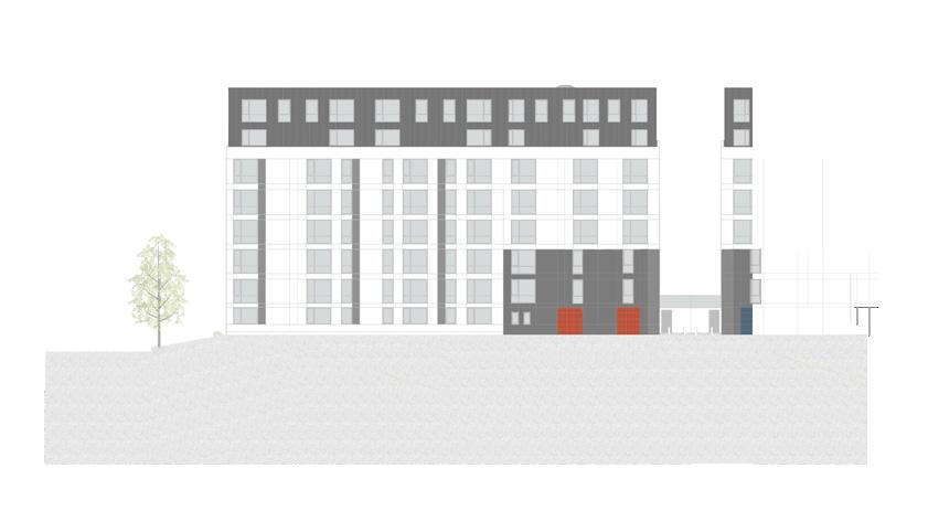
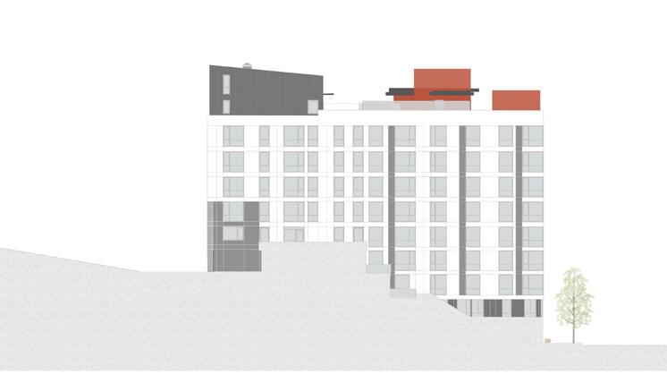
West Elevation

East Elevation
South Elevation North Elevation
PROFESSIONAL
0 1 15 5
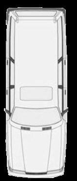
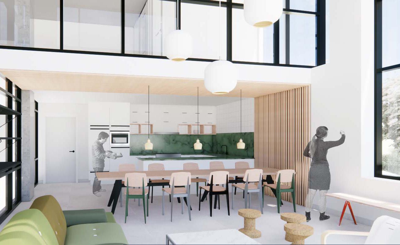
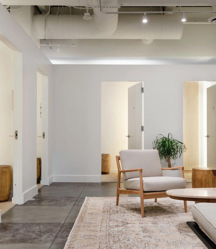
MODERN COMMONS
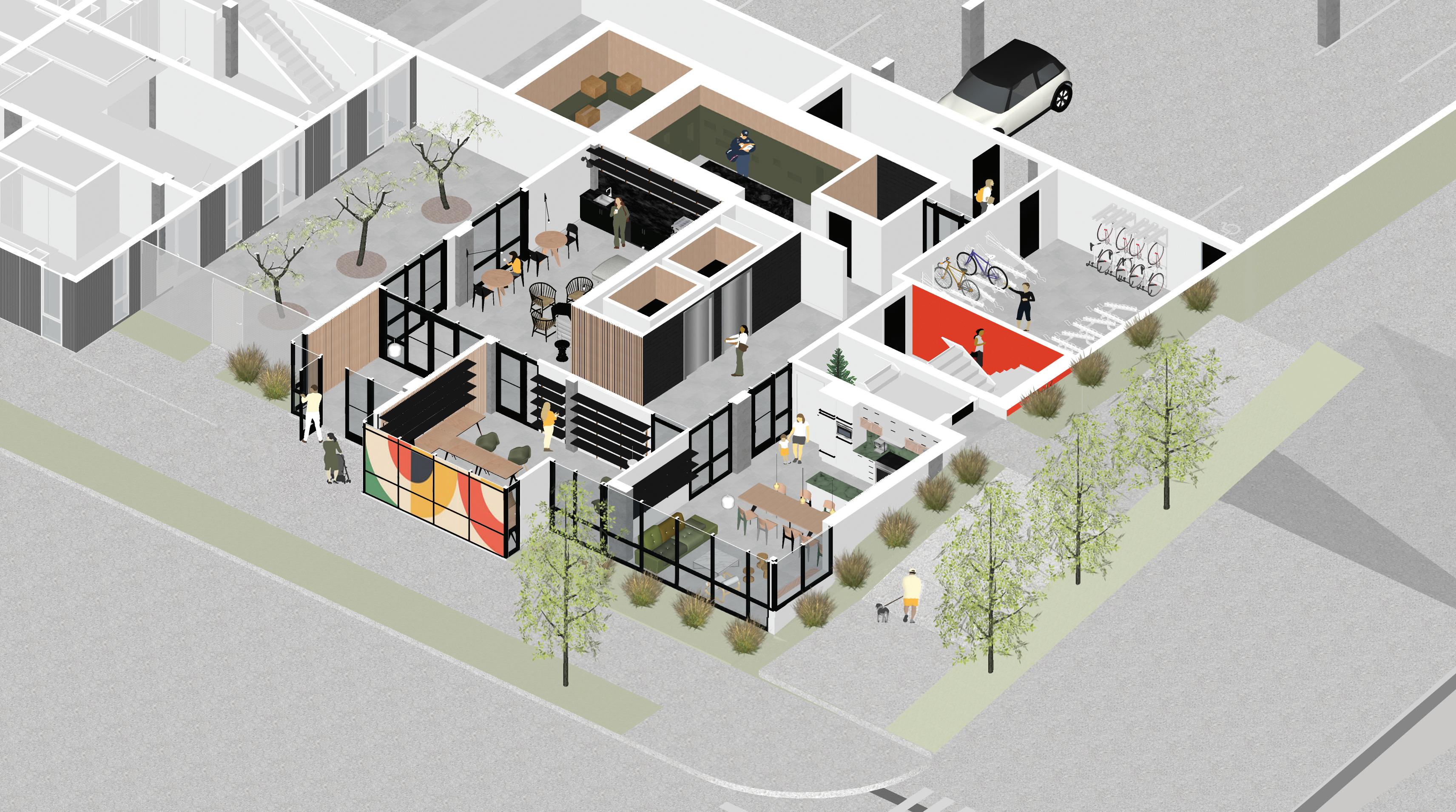
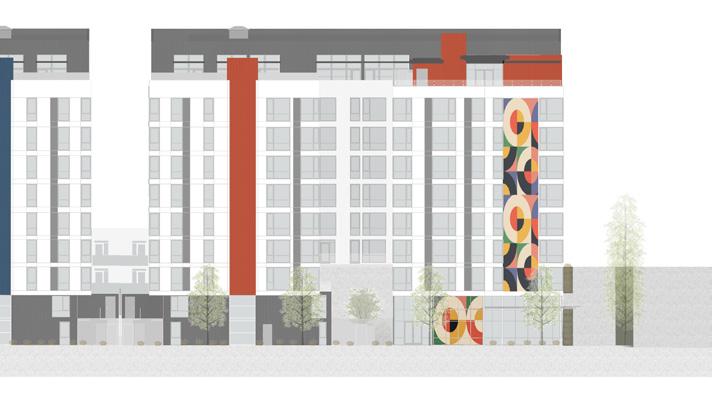
COMMON AREA INTERIOR [2022]
Location: Tacoma, Washington
Floor Area: 3,760 sf
Phase: SD, DD
Software: Revit, SketchUp, Enscape, Photoshop
Role: + Maintain Revit and develop SketchUp models as appropriate
+ Develop exterior design studies and interior design options
+ Collaborate with consultants to maintain design intent with owner specifications
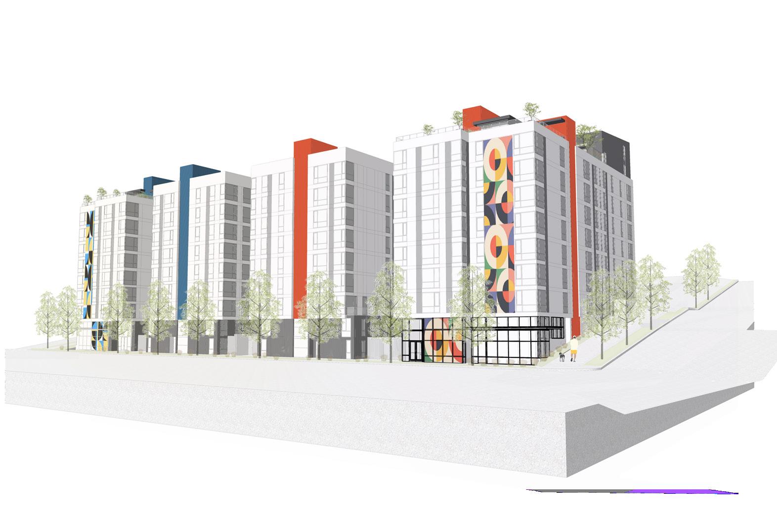
Le Maison Flats and Le Petite are two 10-story mid-rise residential developments, totaling 314 luxury apartment units in downtown Tacoma. The presented exterior perspective, exterior elevations, and interior perspectives are exclusively related to Le Maison Flats.
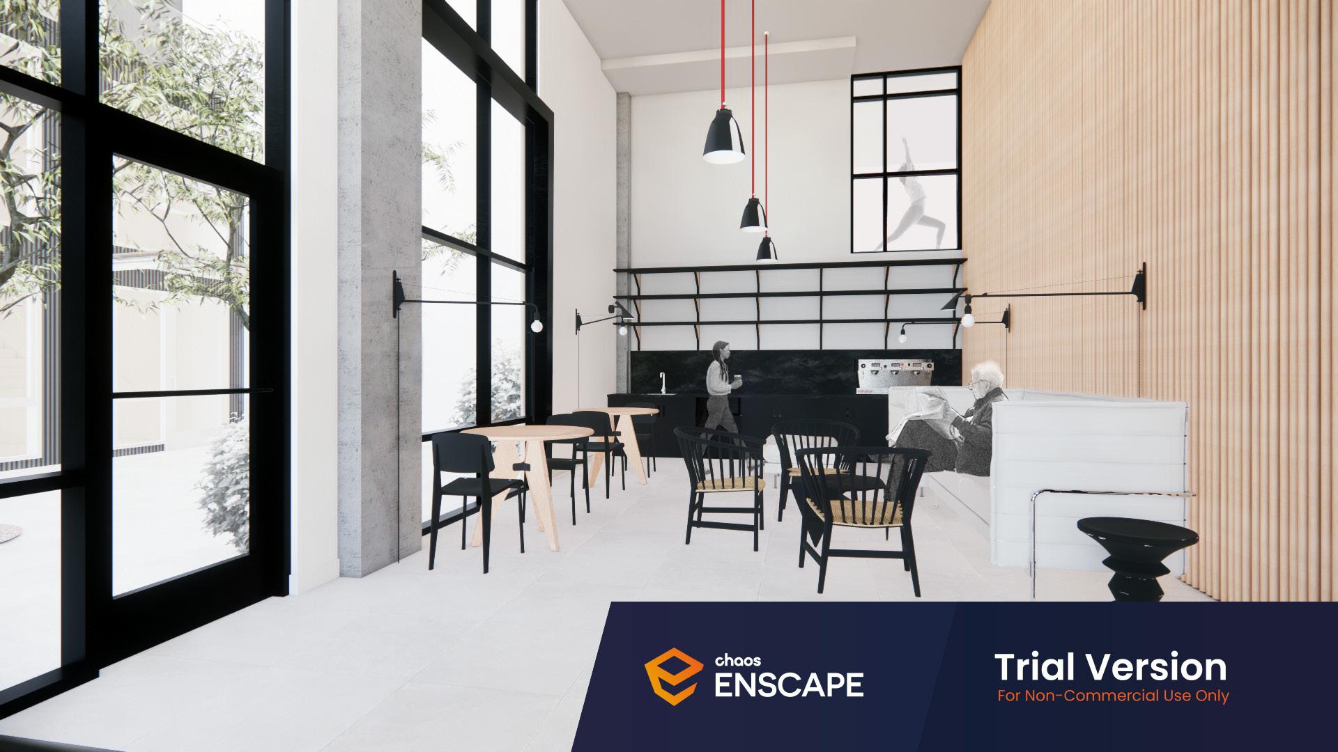
Contributions to this project involve creating digital models for exterior design studies and interior design for common spaces. The featured interior perspectives are one of the design options for client review.
RESIDENTIAL 14 Le Mason Flats Ground Floor Common Space 9 3 1 2 4 5 6 7 8 10 11 12 13 Le Mason Flats / East North West South Le Maison Flats (Red) + Le Petite (Blue) 1 2 3 4 5 6 7 8 9 10 11 12 13 14 Entry Vestibule Lounge Lobby Office Event Room Storage Stair Bike Room Elevator Mail Room Restroom Parking Courtyard
PROFESSIONAL
Lounge / The double-height lounge features muted interiors, drawing focus to the iconic graphic window visible from the nearby office space.
Event Room / Reflecting the building’s design, the event room boasts cohesive interior finishes and furniture. The double-height space is ideal for large gatherings.
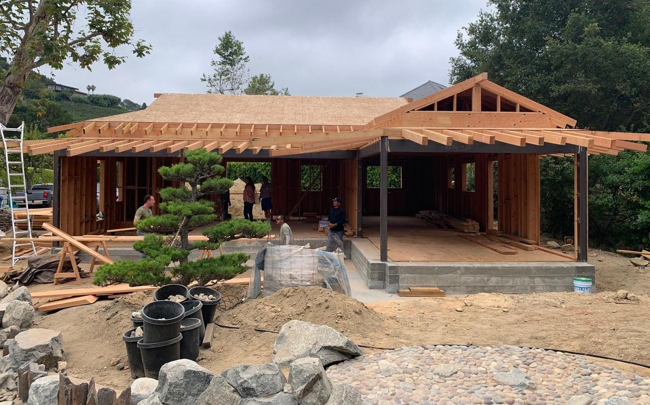
NEW ADU ADDITION [2023]
Location: Los Angeles, California
Floor Area: 1,160 sf
Phase: SD, DD, CD
Software: AutoCAD, SketchUp
Role: + Prepare presentation packages as the project requires
+ Author DD and CD sets
+ Digitize hand-drawn drawings into AutoCAD + Develop and maintain SketchUp model for presentations
This project involves the addition of an accessory dwelling unit to the main house, intended to function as a tea house/guest house for the client, a tea master. The existing tennis court was demolished, and collaboration took place with landscape architects and interior designers in Japan to design the tea practice and event space. My contributions to the project included overseeing graphic communication, such as developing the SketchUp model and preparing documents for design development and permit set.
RESIDENTIAL FLOOR PLAN SCALE:1/4" = 1'-0" N 13'-4" 16'-3" 11'-0" A B D C C' D' 3 4 3 2 1 13'-2" 12'-3" 4'-0" 4'-6" 16'-3" 11'-0" 6'-8" 13'-4" 12" 6'-6" 3'-1" 1'-6" 3'-0" 30" MIN. 24" MIN. 3'-0 1/2" 3'-1" 4'-0" 5'-0" WINDOW W5 1 3'-0" WINDOW W4 1 2'-6" WINDOW W3 1 2'-0" WINDOW 1 W2 2'-0" WINDOW W1 1 D2 D3 D4 D1 4'-0" WINDOW 2'-6" ROUND WINDOW W8 W7 W6 2'-4" WINDOW 1 1 1 D6 D7 D8 D5 4 6 5 7 8 9 11 12 13 14 10 16 19 20 21 22 23 26 27 29 32 31 30 18" 13'-2" 4'-0" 12'-3" B' B C D 4 3 2 A B D C 1'-9" W9 1'-6" WINDOW 1 A A' 2 2 3 24 28 31 30 15 19 18 18 18 3 3 3 32 4'-9" WINDOW 2'-6" WINDOW W11 W10 33 25 13'-0" DN 26 26 26 26 14 35 34 34 35 34 35 35 36 4 36 15'-9 1/2" 9'-3" 6" 12'-5" 15'-8 1/2" VERANDA SLIDING POCKET DOOR SLIDING POCKET DOOR SLIDING POCKET DOOR SLIDING POCKET DOOR TEA ROOM TATAMI KITCHEN WOOD FLOOR FAMILY ROOM TATAMI FAMILY ROOM WOOD FLOOR 36" MIN BATH WOOD FLOOR STORAGE WOOD FLOOR ENTRY 37 38 16 16 SD CD SD CD 1/4" THK. FULL HEIGHT MIRROR 9 10 11 12 13 14 3/8" TEMP. GLASS FRAMELESS SHOWER ENCLOSURE FIBER GLASS SHOWER STALL ULTRA LOW FLOW TOILET PER CAL GREEN WITH 30" MIN. CLR. WIDTH AND 24" MIN. CLR. SPACE IN FRONT. PLUMBING ACCESS PANEL TREATED RED WOOD SLAT LOUVER EACH WINDOW OPENING QUARTZ STONE COUNTERTOP AND BACK SPLASH (TYP.) EAVE OVERHANG ABOVE DOOR PROVIDE 36" X 80" CLR. WIDTH STAIRS 10" TREAD AND 7" RISE WITH 80" ROOM TREATED REDWOOD VERANDA AS SHOWN ENTRY STEPS 12" TREAD AND 7.5" RISE CEILING BATH CABINET WITH LAV. SINK AND FAUCET WOOD SHELVES TO BE DETERMINED 7 8 PROVIDE LED HIGH EFFICIENCY LIGHT FIXTURE IN ENTIRE HOUSE KITCHEN CABINET WITH WALL CABINET W / UNDER CABINET LIGHT 15 PROVIDE GFI OUTLETS AND VACANCY SENSOR SWITCH IN BATHROOM 16 17 PROVIDE CARBON MONOXIDE DETECTOR PROVIDE ENERGY STAR EXHAUST FAN W/HUMIDITY CONTROL IN BATHROOM 18 WALL LEGEND INTERIOR PARTITION WALL 2X4 2X6 @ 16” O.C. 5/8” GYP. BD. BOTH SIDE PROVIDE R-15 INSULATION AT BATHROOM WALL EXTERIOR WALL 2X6 @ 16” O.C. 7/8” STUCCO OVER PLYWOOD SHEAR OUTSIDE AND 5/8” GYP. BD. INSIDE PROVIDE R-21 INSULATION (TYP.) PROVIDE HOSE BIB SHOE CLOSET DOOR POCKET 2X4 @16" O.C. DOOR POCKET 2X4 FLAT @ 16" 1 1/2" THICK DOUG-FIR FRAME AROUND
Ken Tanaka Studio TEA HOUSE
A’ A B C D B’ C’
D’ FLOOR PLAN SCALE: NTS
Photo: Courtesy of Ken Tanaka Studio
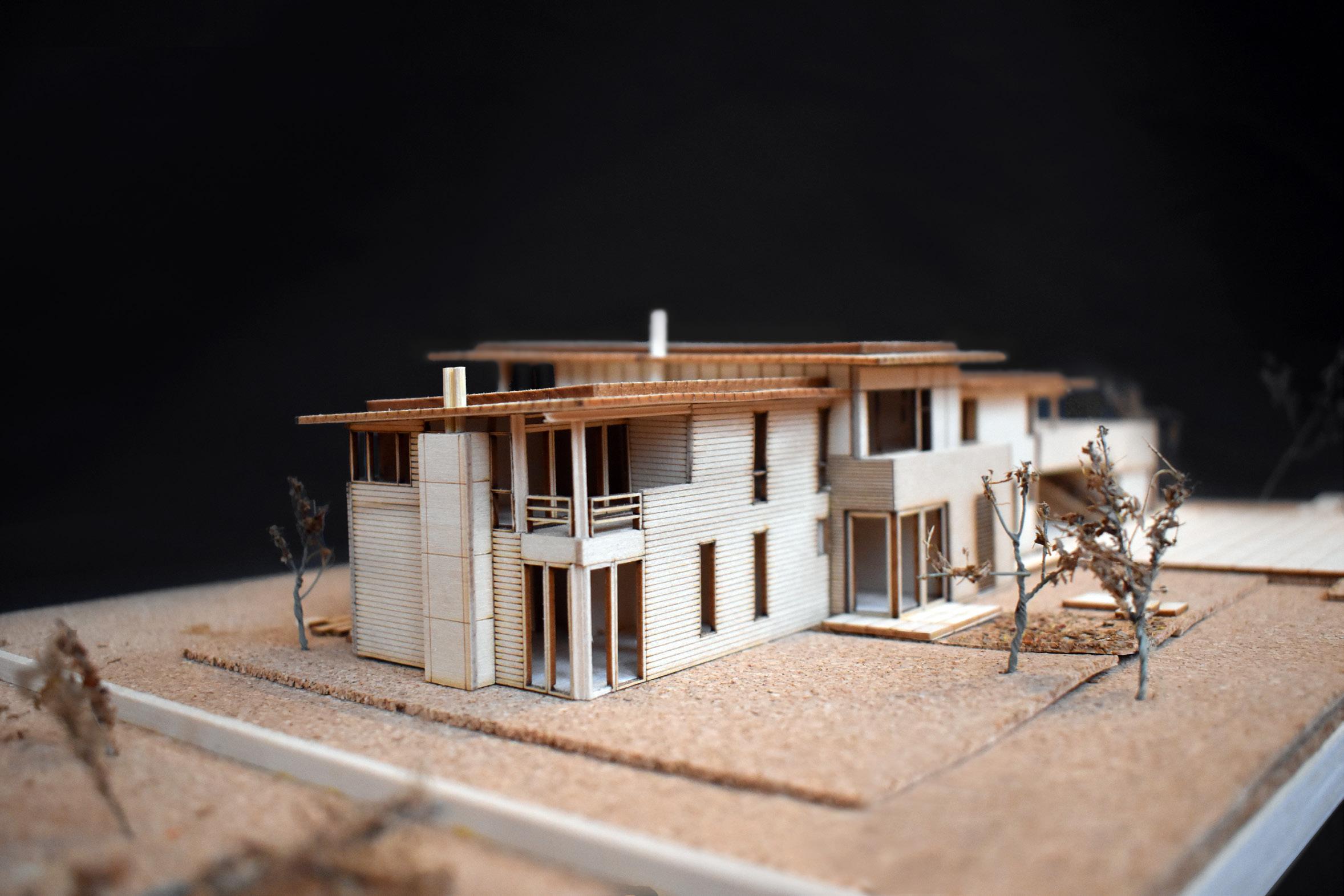
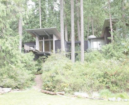
HOUSE TO LAST 100 YEARS
Ueda Design Studio
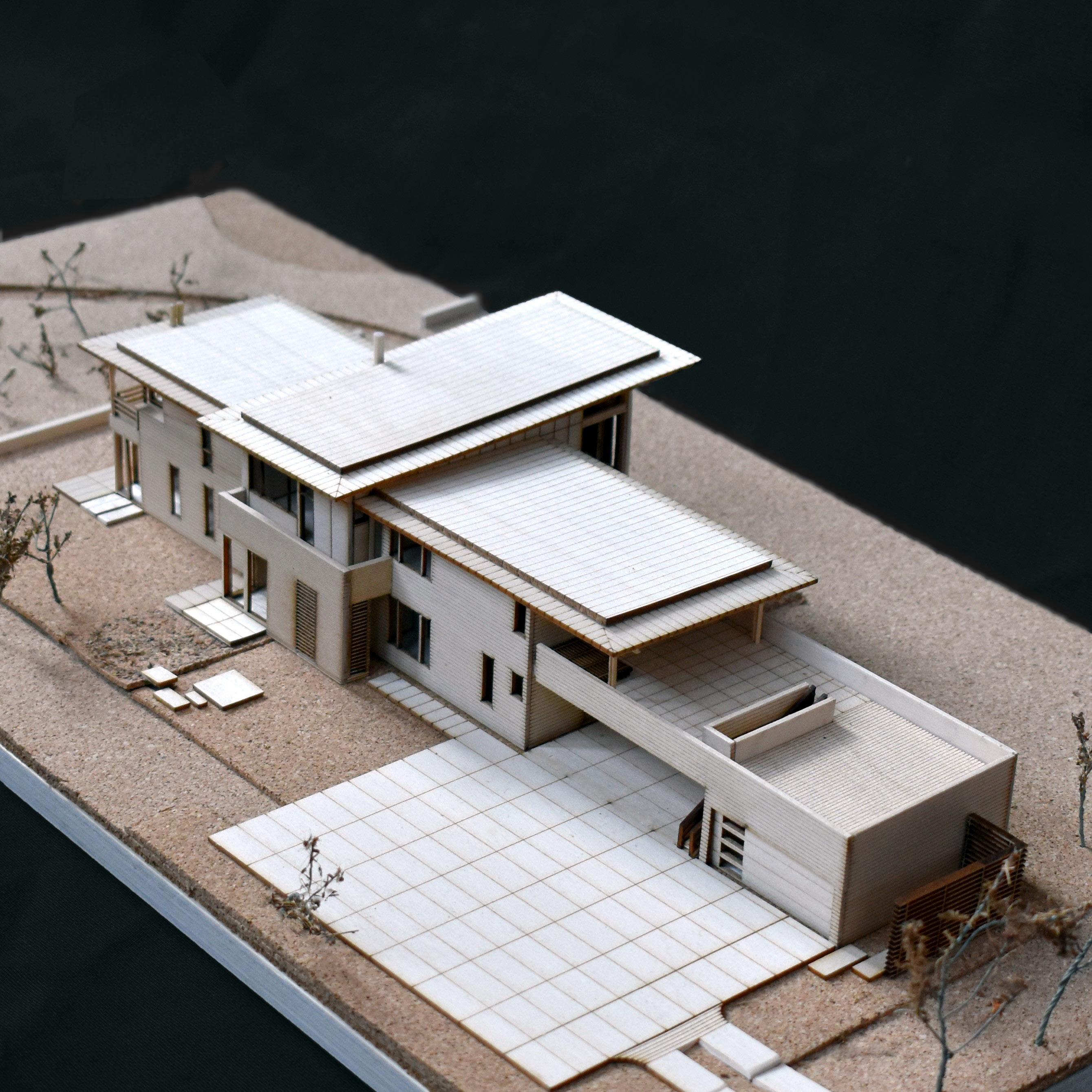
HIGH PERFORMANCE HOME [2019]
Location: Salem, Oregon
Material: Scaled Beams, Basswood, Cork
Scale: 3/32” = 1’-0”
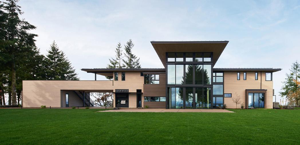
The façade harmoniously combines cedar shiplap siding, fiber-cement board, concrete, and steel, embodying simplicity, timelessness, and low maintenance.
Software: Revit, Rhino, SketchUp, Illustrator
Role: + Review plans and 3D models (Revit and SketchUp)
+ Prepare model cutout parts using Rhino and Illustrator
+ Construct the model under the supervision and with periodic reviews by a senior architect
This physical model was crafted during my internship at Ueda Design Studio in 2019. The model components were created through a combination of laser cutting and manual assembly, carefully incorporating various scaled beams and basswood.
The project is an 8,000 sqft newly built single-family home in Salem, Oregon. Sustainability is a driving force for the design of this project, and the goal is to create a high-performance, energy-efficient building to last for the next 100 years.
RESIDENTIAL
Nestled on the top of the Eola Hills, this house commands an elevated position, offering captivating panoramic vistas of the surrounding landscape.
Photo: Courtesy of Ueda Design Studio
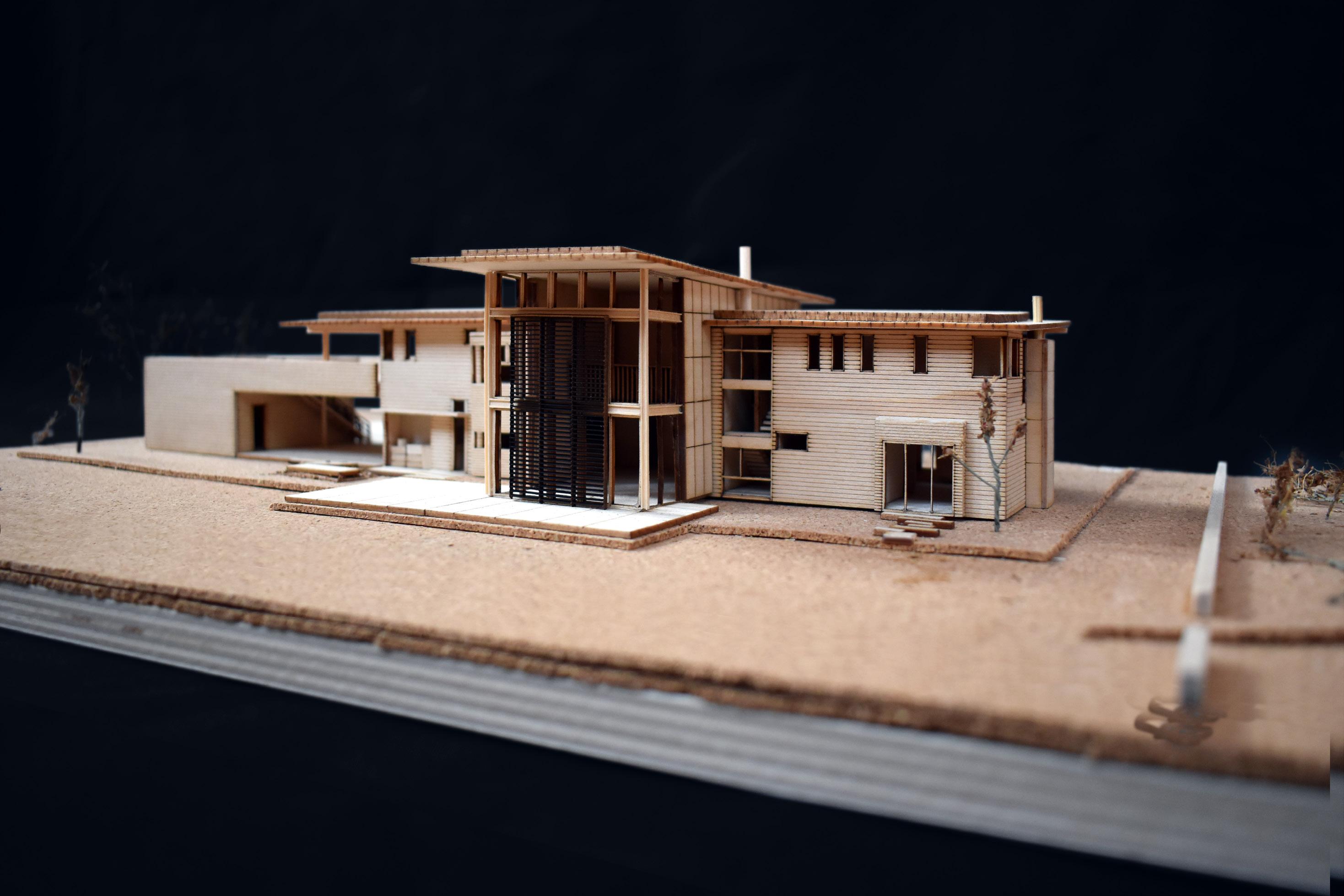
The HVAC system includes highly efficient heat pumps and a hydraulic radiant heat system. Awning windows at the top of the dining window wall open to cool down the space before the A/C kicks in, and automatic exterior sunshades reduce solar heat gains from the intense summer sun.
The house is enveloped with continuous exterior insulation and a rain screen system and topped with metal roofing. It features high performance aluminum windows and doors throughout.
PROFESSIONAL
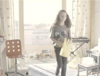
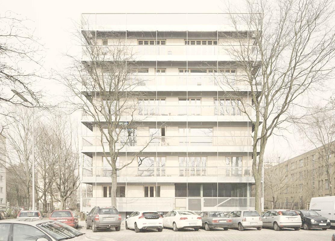
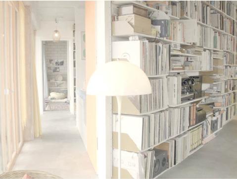
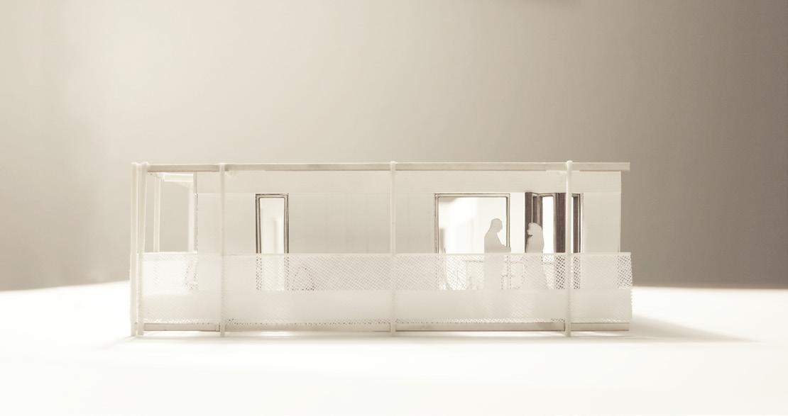
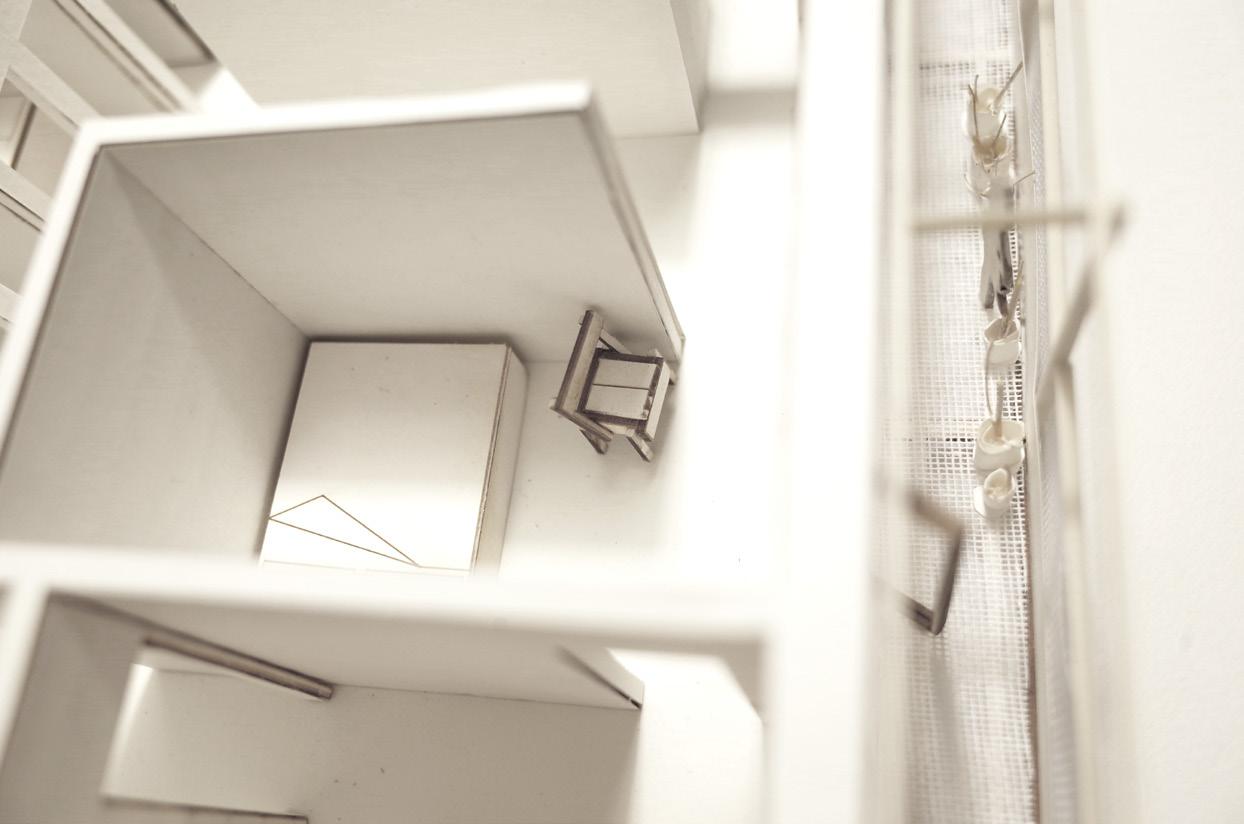
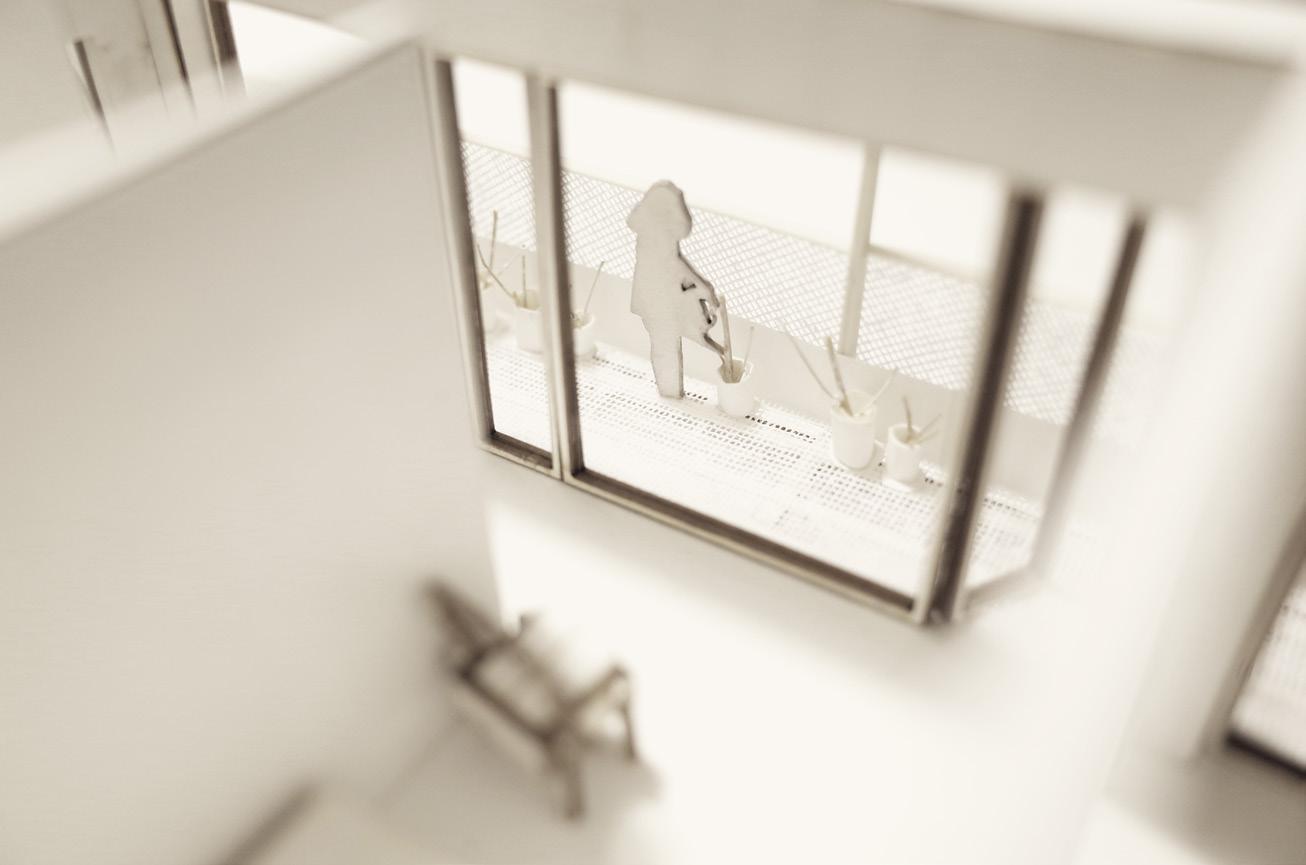
BLURRED URBAN ROOM
The blurred boundary between your space and my space
CASE STUDY + MODEL BUILDING [2019]
Location: Berlin, Germany
Material: Cardboard, basswood, paper, textile, noodle
Scale: 1/4” = 1’-0”
Software: Rhino
This unit model was developed as a case study for the multi-family housing seminar at the University of Washington in 2019. The R50 project, designed by Berlin-based architects, introduced a novel urban co-housing concept called baugruppen. In this project, the architects assumed both the traditional and developer roles, showcasing the potential of a new urban housing model and redefining the architect’s role.
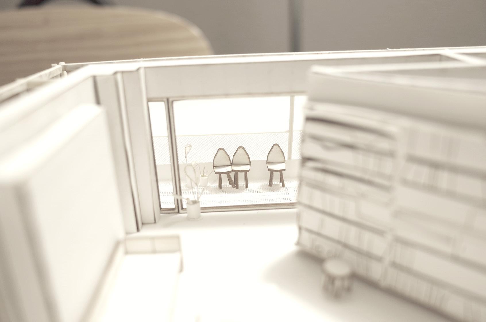
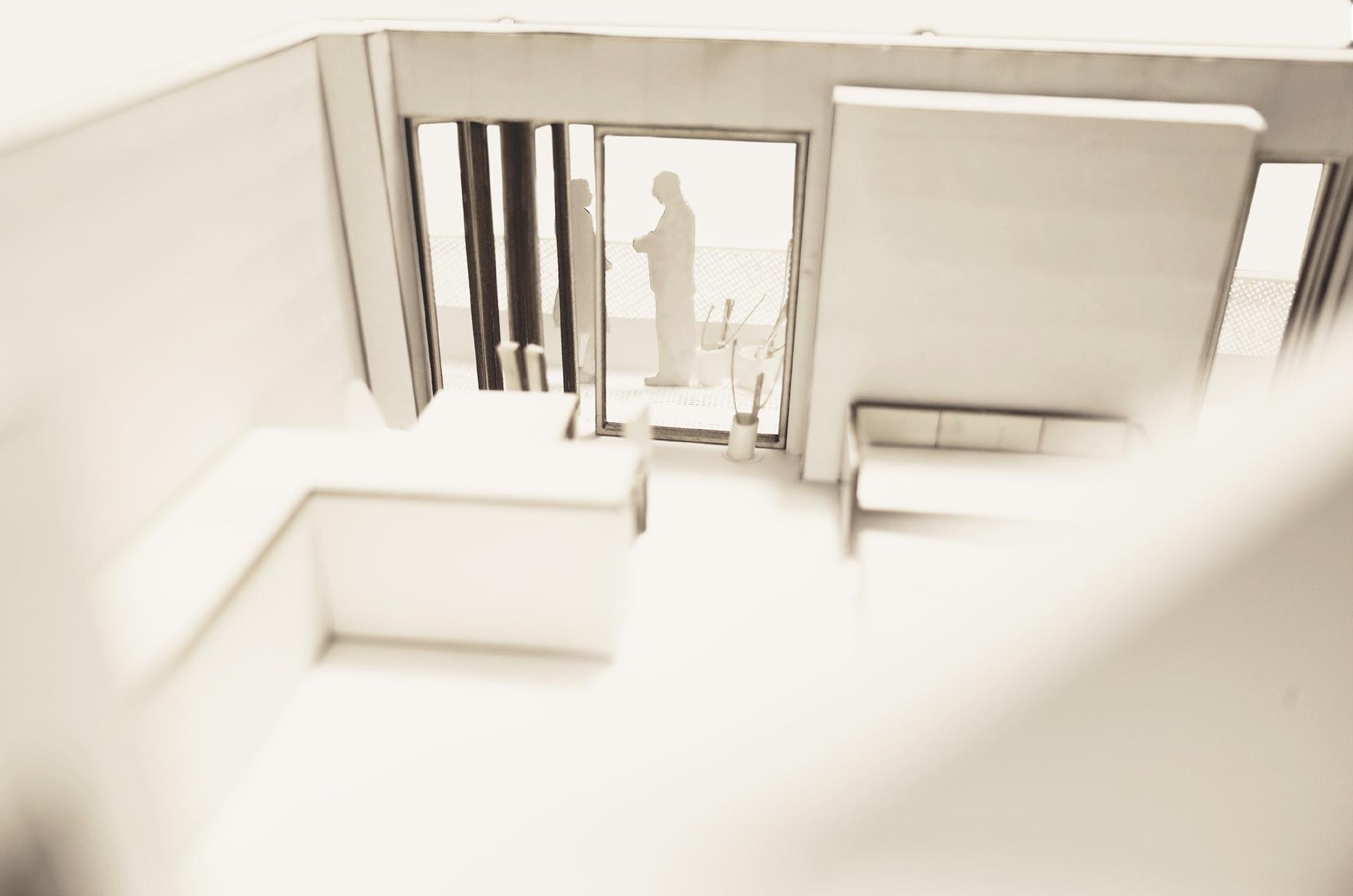
Distinctive balconies are wrapped around the building on each floor, and the design fosters a sense of community by providing shared private space accessible to all residents. On top of the innovative housing concept, I was particularly drawn to the design solution blurring the boundaries between residents’ private and shared private spaces within the co-housing building. This unit model components were crafted using laser cutting and manual assembly techniques, incorporating cardboard, basswood, fabric, and dry noodles. The focus was on depicting how shared private spaces were utilized around the unit, offering insights into the spatial quality within the cohousing environment.
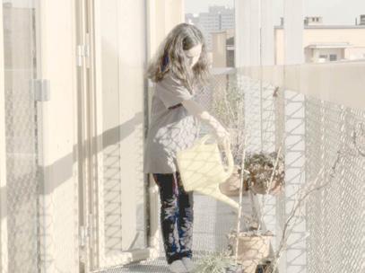
Balcony: The wrappedaround balcony is open to any residents, so the balcony is shared with neighbors, but the plants belong to her more visually from her room.
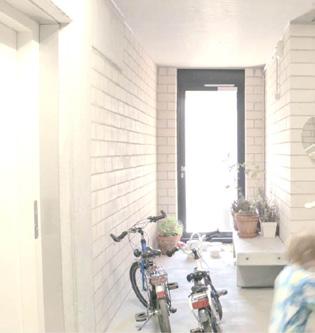
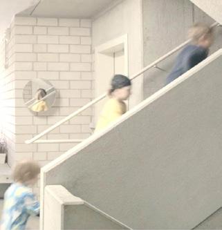
Circulation: Like the balcony, it is a shared private space for the residents and a private space for someone to keep their bikes and plants.
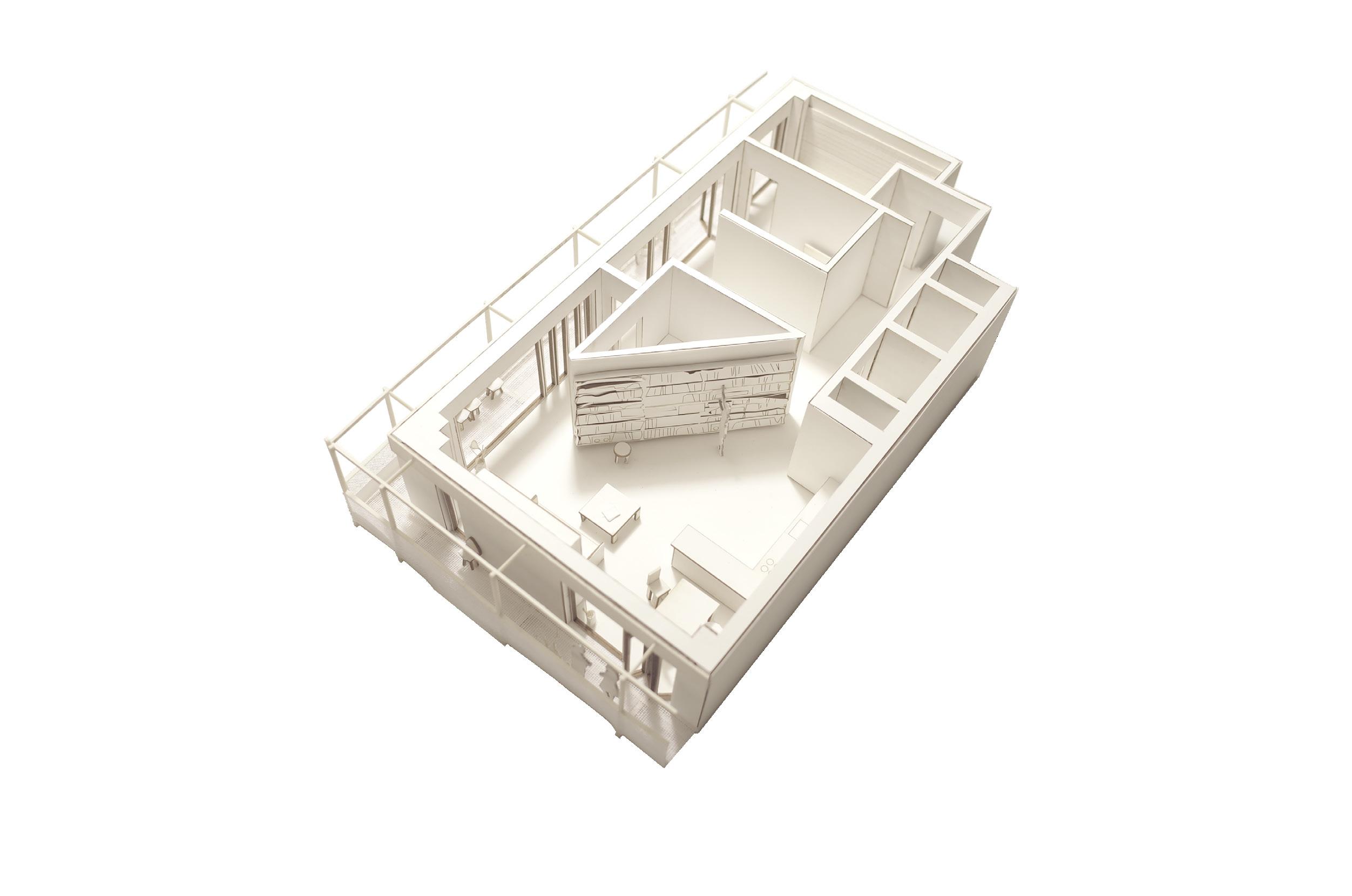

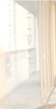
My unit and our balcony: The living space, interior hallway, and balcony are one space and conceptually all belong to the unit resident, but the balcony is shared with neighbors and functions like a back alley.
RESIDENTIAL
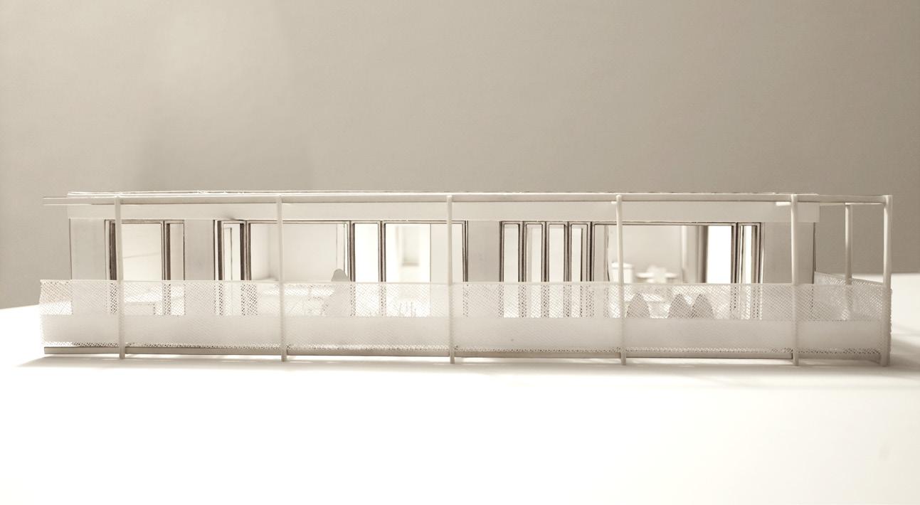
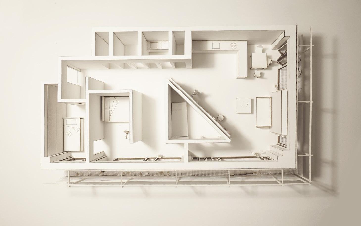
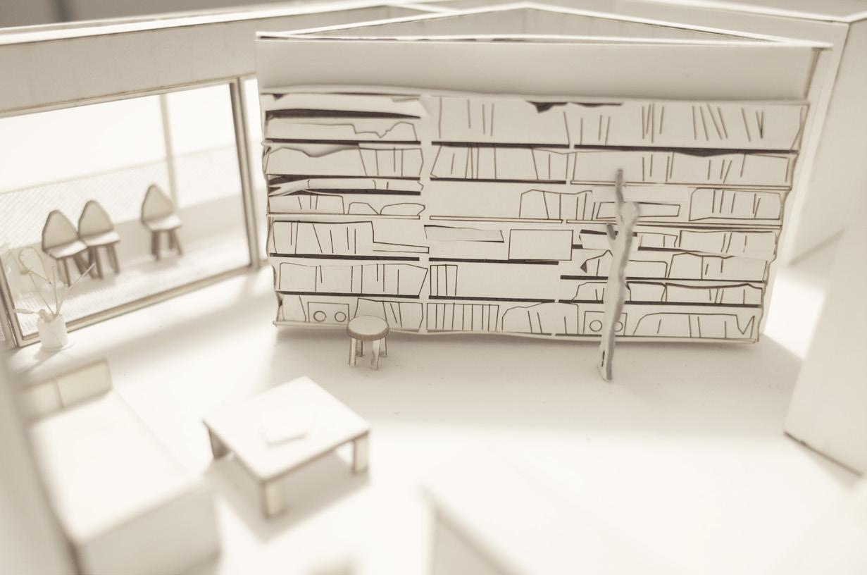
ACADEMIC Entry Hallway Bathroom Storage Kitchen Dining Living Book Shelve Bedroom Balcony 1 2 3 4 5 6 7 8 4 9 9 10 10 1 2 3 4 5 6 7 8 9 10 Unit Plan West Elevation South Elevation 2 2
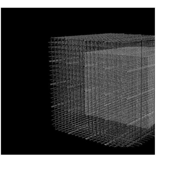
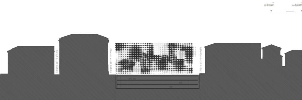
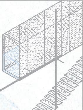
ETERNAL TENTATIVE
How can we integrate the present into the historical city?
OUTDOOR CINEMA [2018]
Location: Via Giulia, Rome, Italy
Floor Area: 33,600 sf
Program: Theaters, Ticket Office, Visitor Center, Office, Piazza, Cafe, Bathroom, Parking
Software: Rhino, SketchUp, AutoCAD, Photoshop
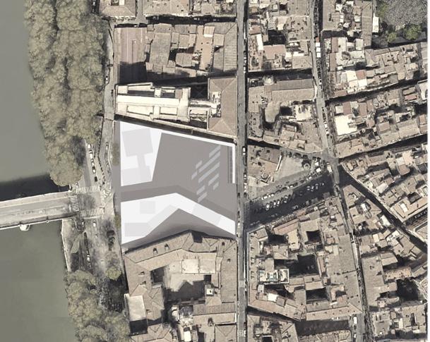
Via Giulia, constructed during the Renaissance in Rome, underwent disruption in the 1930s when Mussolini demolished historic buildings, leaving a vacant plot at Piazza della Moretta for over eighty years.
Initially serving as a parking lot above an underground archaeological site, the area transforms into a new urban piazza featuring an outdoor cinema, infusing a contemporary breeze into Rome’s historic cityscape.
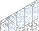
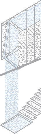
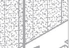
The theater is structured with a 3D steel grid incorporating void spaces for indoor programs, allowing easy transformation according to program needs. Depending on perspective, this flexibility and visual changes signify eternal contemporariness, revitalizing the historical cityscape.
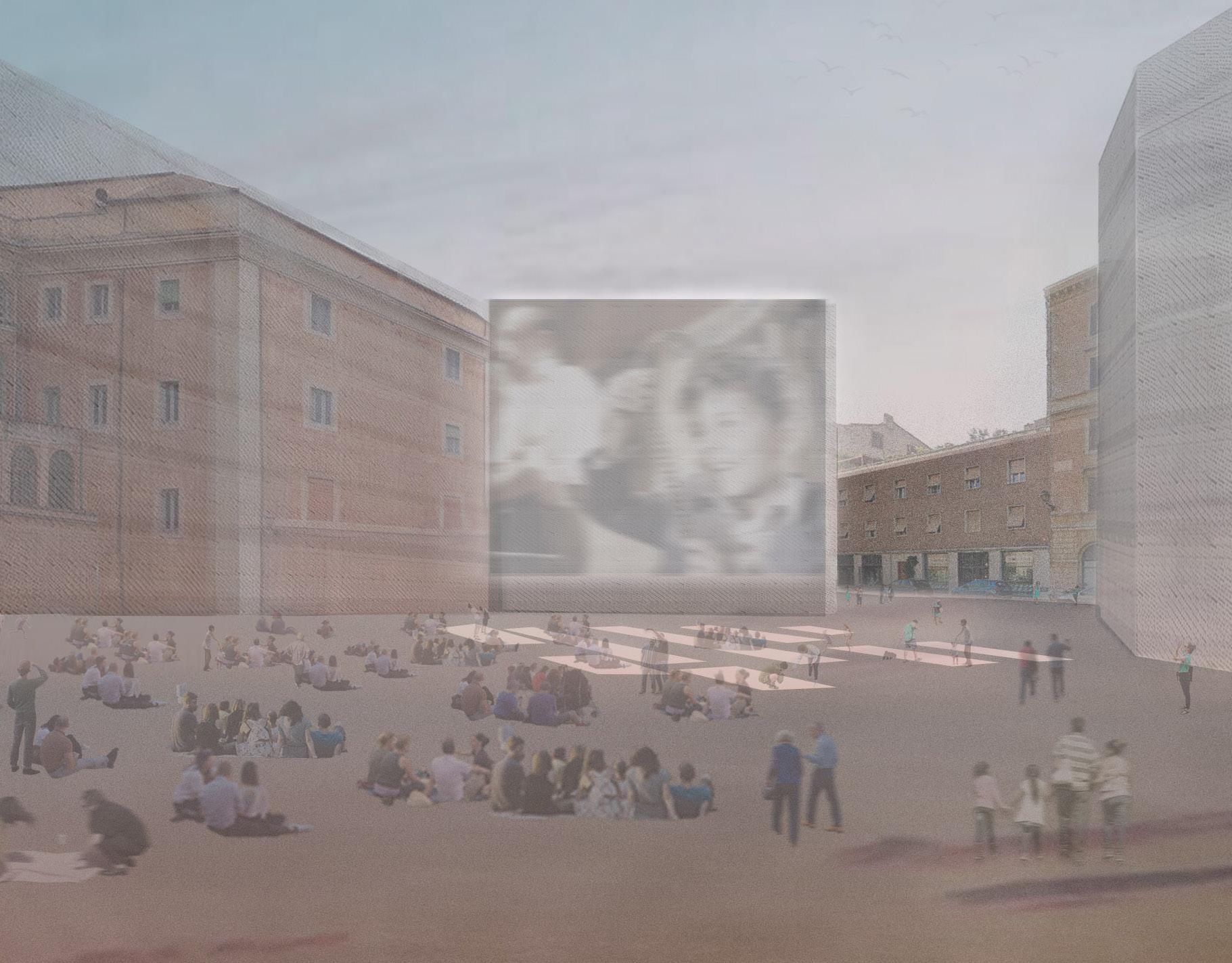
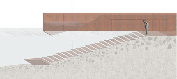
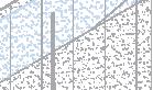
The sloped terrain of the outdoor cinema invites visitors to recline on the piazza ground, providing a unique viewpoint to enjoy the suspended movie screen while occasionally glimpsing underground archaeology. This immersive experience allows users to savor the moment while reflecting on the area’s rich history.
Site Piazza della Moretta

Conceptual Sketch - New Cinema in the Via Giulia Site
CULTURAL
Twilight show at the outdoor cinema piazza
Steel Grid System
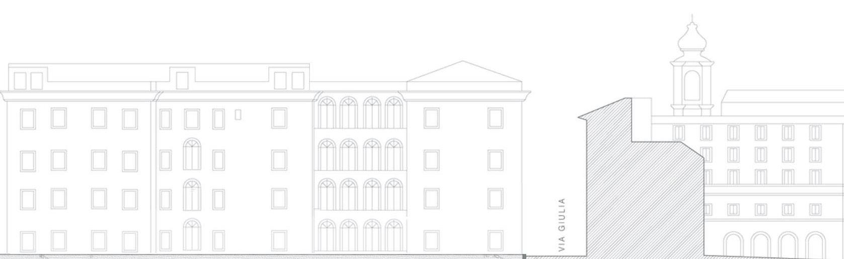
Plan
Via Giulia


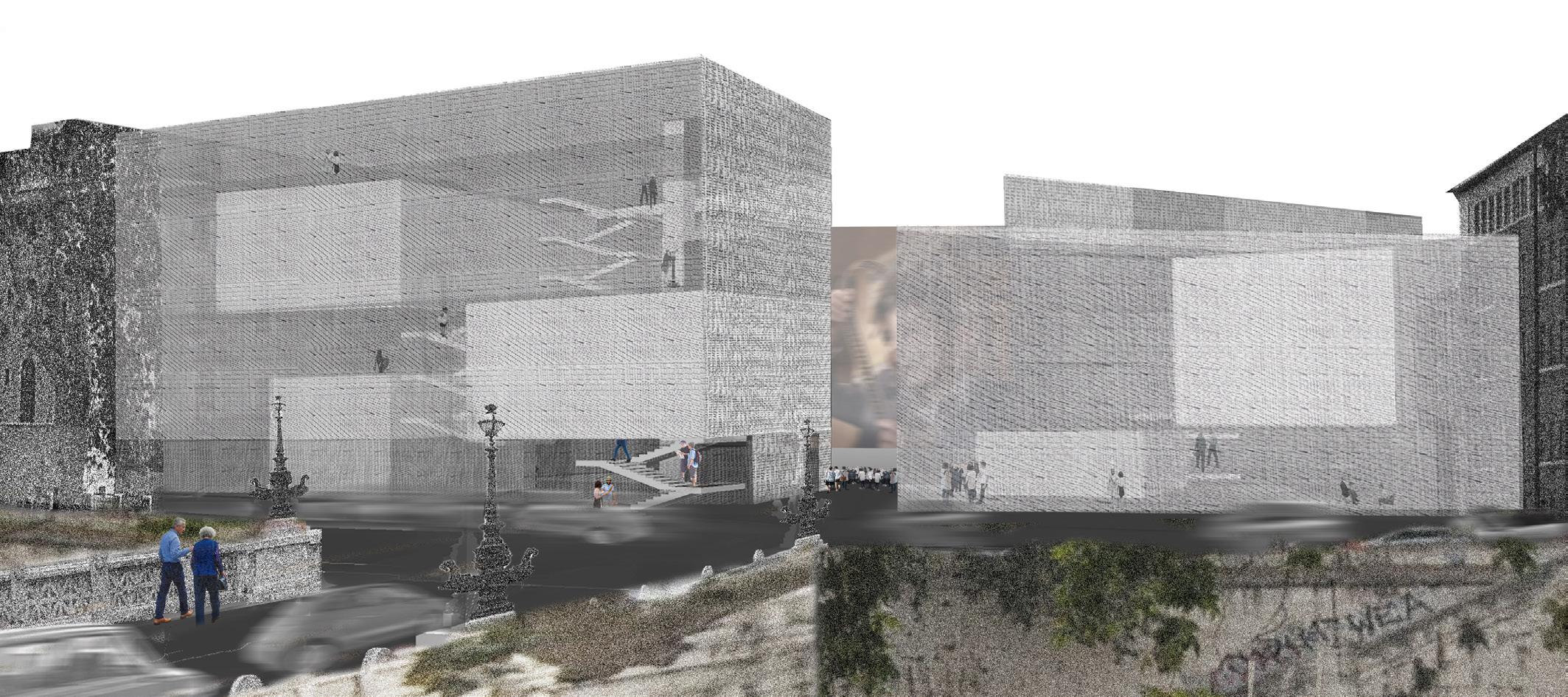
ACADEMIC Facade looking from the Tiber river 3 2F 3F 3 3 3 Entry Ticket Office Outdoor Cinema Observation Window Cafe Patio Public Bathroom Visitor Center Rooftop Hallway Indoor Cinema Office Parking Entry/Exit 1 2 3 4 5 6 7 8 9 10 11 12 13 New Piazza Cinema Screen Existing Piazza Level 3 Level 2 Ground Level Section A-A’ A L A’ L Via Giulia Via Giulia Lungotevere dei Sangallo Lungotevere dei Sangallo VicolodellaMoretta 1 2 8 8 8 13 5 11 11 9 7 12 12 4 9 Level 4 8 9 11 6 8 6 Via Bavaria Via Bavaria Archaeological Site Indoor Programs 0 10 80 40 PiazzadellaMoretta 6 9 9 4F
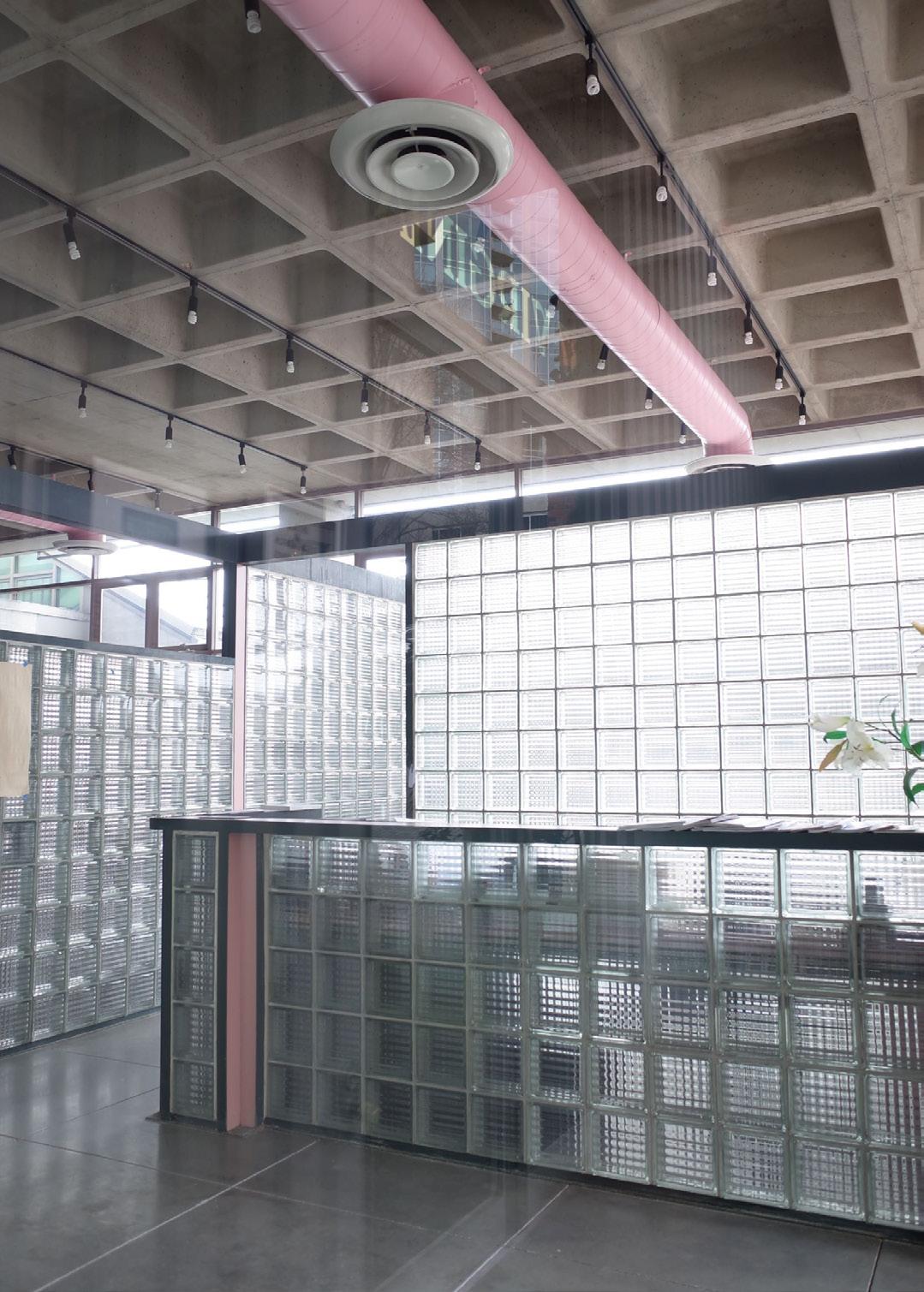
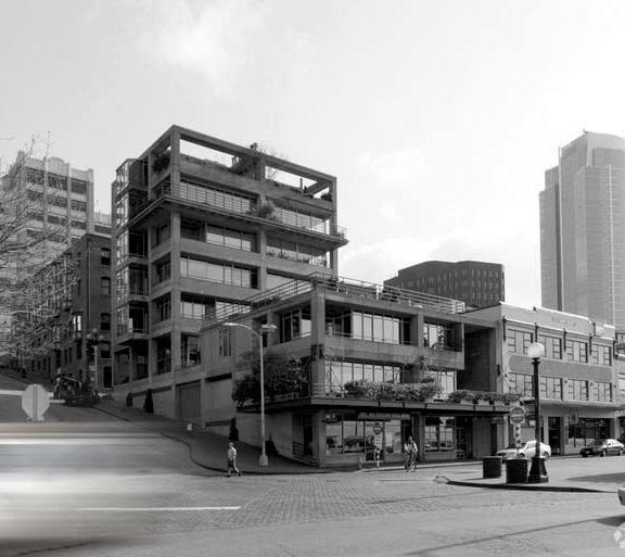
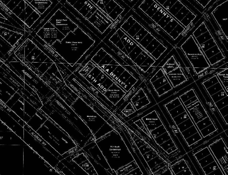
QUIET VIEW
A story of urban grids
MIXED USE RESIDENTIAL - RENOVATION [2018]
Location: Seattle, Washington
Floor Area: 1,853 sf
Program: Living Room, Patio
Software: SketchUp, Photoshop
This mixed-use project, built in 1978 in the Pike Place Market historic district, comprises an eight-story residential building with street-level retail space. The top-floor Unit 14 has been renovated for the project. By reducing visual grids, the idea is to provide users with gradual visual tranquility as they journey back from the lively waterfront neighborhood to their residence.
The renovation focused on a single room and the adjacent patio. The waffle slab ceiling is covered with wood ceiling, which matches the floor and wall. A new window/door system was introduced, with openings lowered to match the eye level when reclining in a lounge chair. The ceiling height was also slightly lowered to emphasize a horizontal sense promoting sitting postures. From the window, a vertical garden on a green patio is visible, providing a spatial contrast when stepping out onto the patio from the room with a lower ceiling. The three grids of floor, green wall, and the sky are apparent. Looking up at the sky, only one grid framed by walls on all sides is visible, reaching the pinnacle of tranquility experience.
RESIDENTIAL
1 3 2
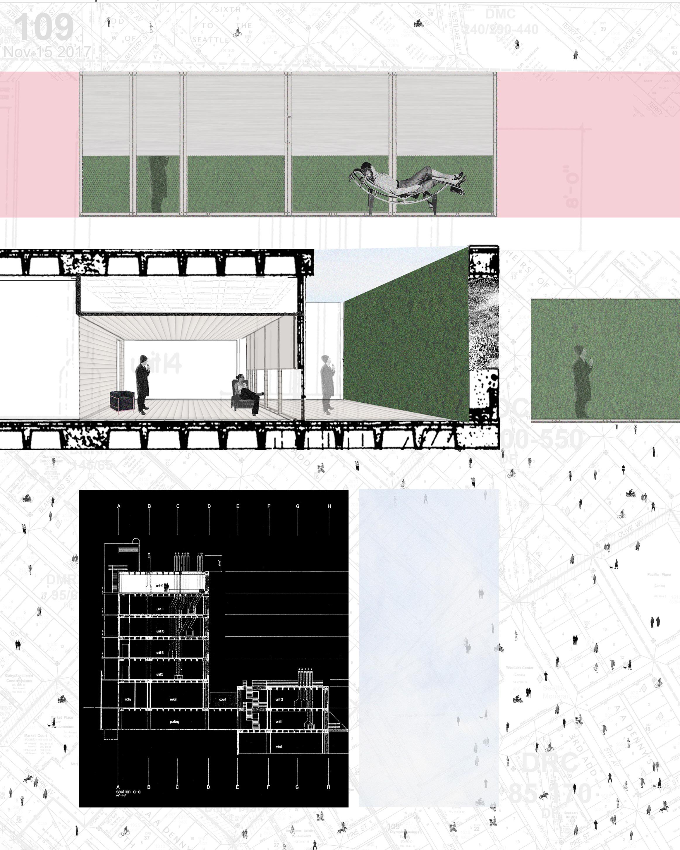
ACADEMIC 4 6 7 8 5 Urban Grid Building Grid Lobby Grid Unit Grid Room Grid Wall Grid Patio Grid Framed Sky Grid 1 2 3 4 5 6 7 8
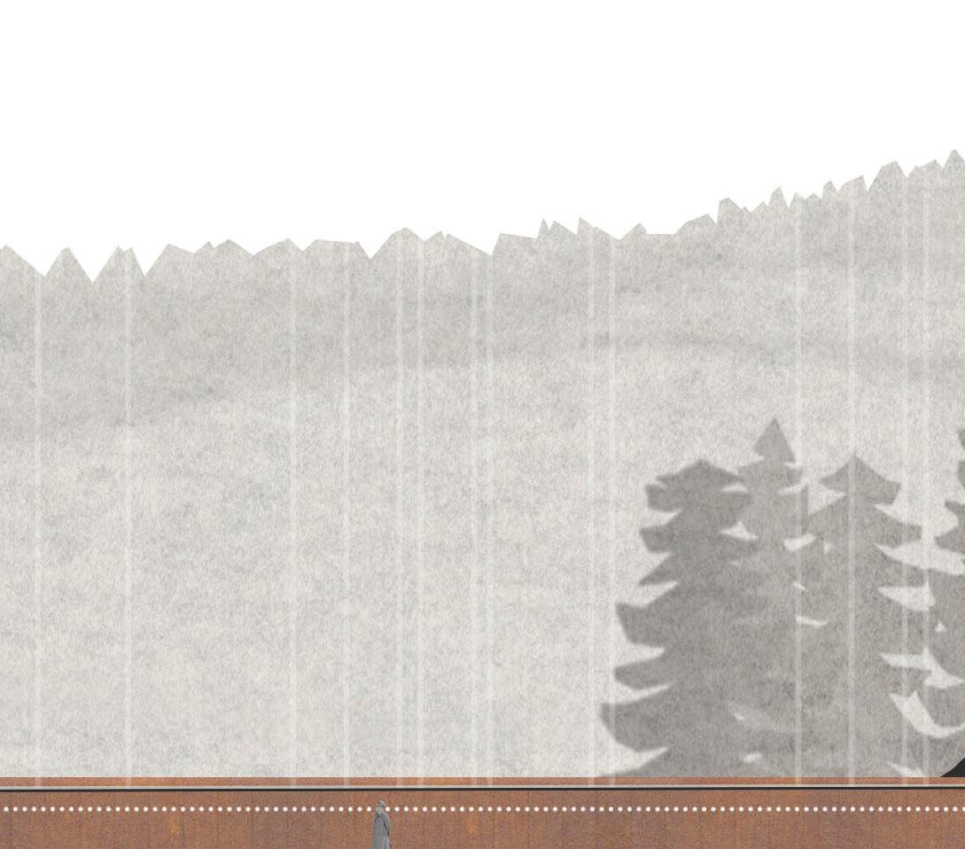
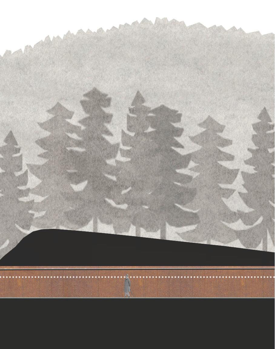
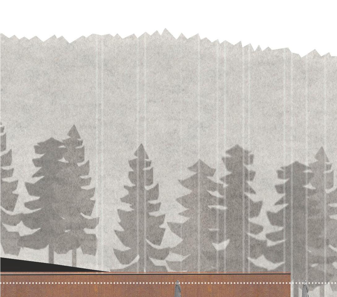
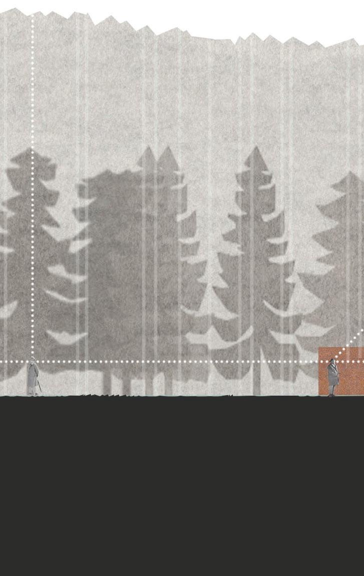
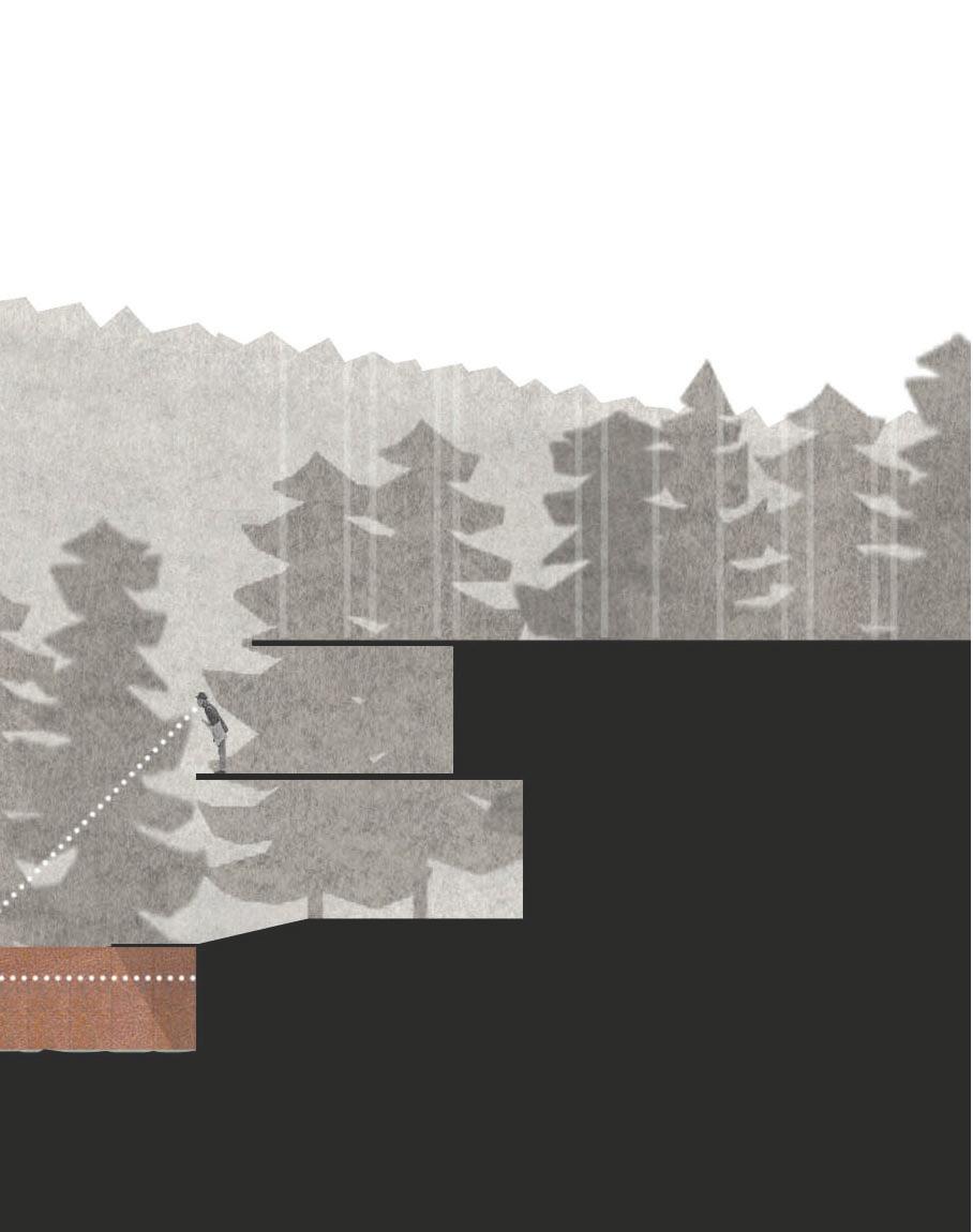
INTERRUPTION
Making a pause in life
VIEWING PL ATFORM [2018]
Location: Longbranch, Washington
Floor Area: 1,440 sf
Program: Viewpoint, Hallway, Shower
Software: Rhino, Photoshop
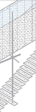
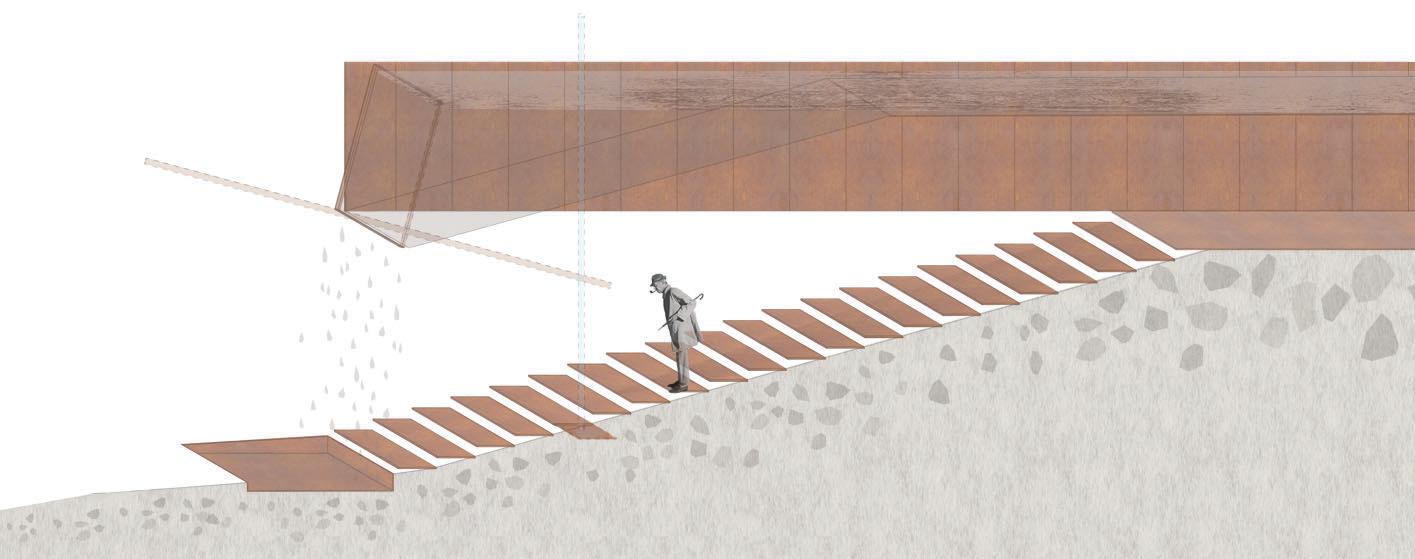
The project involves an addition to a beach house situated in Longbranch. Originally constructed in 1959, the house has undergone several renovations over the years. This extension project aims to capture the organic evolution of the house and the passage of time.
A significant design element is a long cuboid tunnel serving as a rain gutter, directing water from the forest to the shoreline. This flow symbolizes the passage of time, occasionally interrupted by spatial events and natural phenomena on its journey into the future


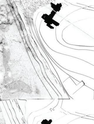

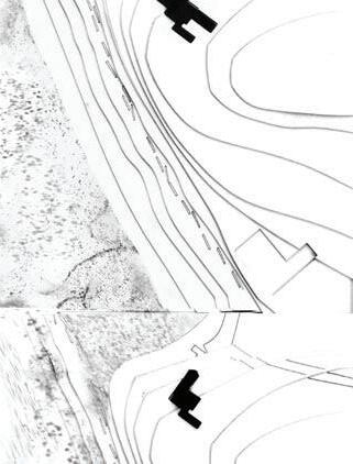


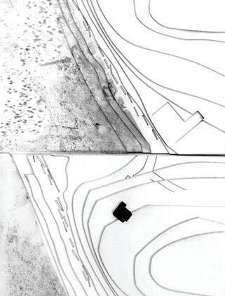


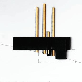


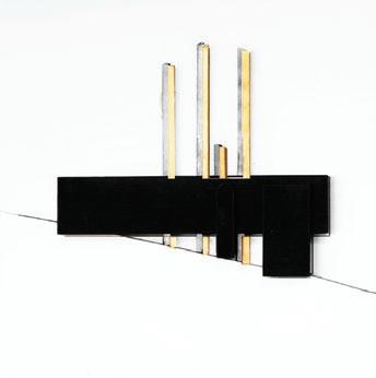


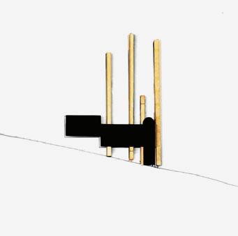

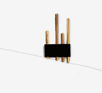

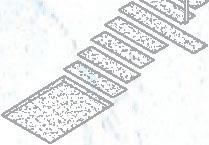
ART INSTALLATION Growth of the Beach House 2003 2014 10pm Time+Tide 3pm 8am 3am Beach House / 2014 1959 19881 Concept Diagram + Site Model / 2018 viewpoint A’ w m / point e D Concep Mo te nt v A L L 30 15 0


/ High tide 8 am
/ Low tide 3 pm ACADEMIC Plan+Section A-A’ / Low tide 3 pm
Viewpoint
Viewpoint
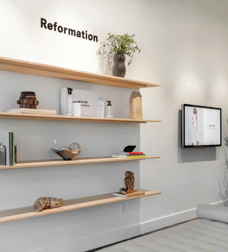
REFORMATION [2021]
Location: Seattle, Washington
Floor Area: 2,400 sf
Phase: DD, CD
Software: AutoCAD
Role: + Prepare drawing sets for the project manager to review
+ Make site visits to document existing conditions
+ Participate in day to day project management
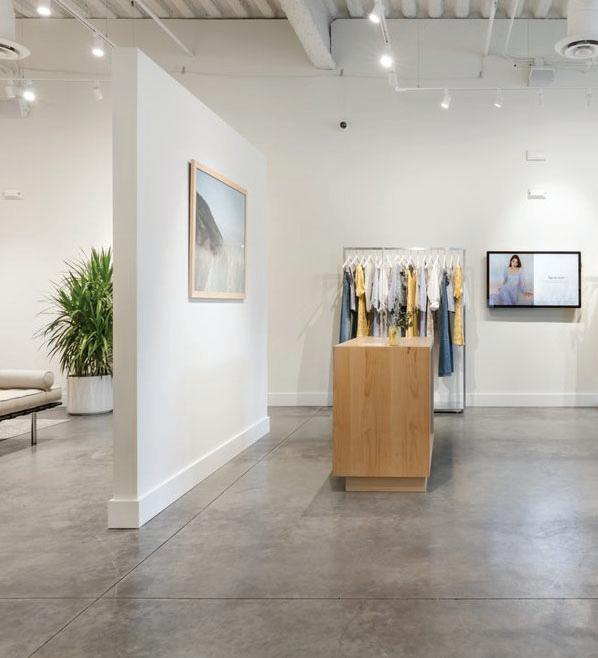
The low and high tech retail project is a tenant improvement for the Seattle branch of the clothing brand Reformation, located in an urban shopping mall in Seattle. The emphasis is on elevating the interior design of a single-story retail space. The provided drawings were crafted to obtain a subject-to-field inspection permit during my tenure at GM Studio


Display
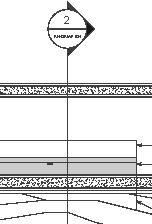
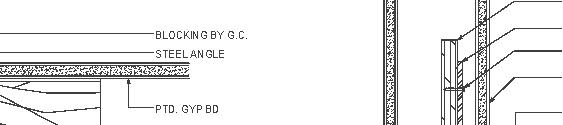
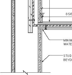
Display Shelf Detail Photo:
GM STUDIO LOW & HIGH TECH RETAIL
RETAIL Floating
Courtesy of Reformation
1 Floating
Shelf Section 2 SCALE: NTS BREAK METAL EMBEDDED INTO WALL, G C TO COORDINATE PLYWOOD 5 1 4" INSET AROUND 3 SIDES TO ENCAPSULATEMETAL ANGLES SHOWN DASHED 5 1 4 5 1 4" NEWWALL BLOCKING BY G C. STEEL ANGLE BY MILLWORKER LAG SCREW PATCH, REPAIR AND PAINT GYP BD. AS REQUIRED PLY WOOD 14 3/4" 3 1/2" 1 INIMIZE GAP AND CAULK ATERFEALL EDGES, TYP. D FRAMING ND SCALE: NTS c b a
29'-2 1/2" 30'-4 1/2" 30'-4 1/2" 31'-1" 57'-6" 30'-0" 4" 3'-0" 7'-7 3/4" 27'-10" 5'-2" 5'-2" 5'-2" 5'-2" 5'-2" 5'-2" 5'-2" 5'-0" 24'-4" 12'-5" 16'-3" DRM PS&IH MWR 1 1 1 1 1 1 1 2 E3 E2 E1 WM TS TS WS WS FS EXISTING KITCHENETTE TO STAY AS IS EXISTING WINDOW SILL TO STAY AS IS TYP. OF TWO NEW WALKOFF MAT AT EXISTING LOCATION CC E.Q. 8'-0" E.Q. 1 2 3 4 E D STORAGE UNIT STORAGE UNIT STORAGE UNIT STORAGE UNIT FSR FSR FSR FSR FSR FSR 13'-5" 4'-9" A.F.F. 1'-11" 5'-9 1/4" 8'-0" 8'-0" 6'-6" 14'-6" 1'-5" 1'-5" 1'-5" 10'-0" 4'-6" 14'-6" 42" H WS DUAL SIDED WARDROBE 1 1 1 1 7'-0" 4'-9" A.F.F. STORAGE UNIT STORAGE UNIT FS 42" H WS E1 D E FSR FSR FSR 8'-0" 6'-6" 14'-6" 6" 7'-6" 42" H WS STORAGE UNIT WM 4'-9" A.F.F. 4'-9" A.F.F. DUAL SIDED WARDROBE 3 2 1 FSR FSR FSR 42" H WS 8'-0" 6'-6" 14'-6" 7'-0" 2 E D Floor Plan Section A-A’ Section B-B’ Section C-C’Section D-D’ A’ A B B’ C’ C D’ D PROFESSIONAL CC DRM FS FSR IH MDR PS WM WS Checkout Counter Dressing Room Monitor Floating Shelf Free Standing Clothing Rail IPad Holder Magic Wardrobe Rack Phone Shelf Wall Mounted Mirror Wall Mounted Screen Key Notes: 1 2 3 4 5 6 7 8 9 10 Entry Display Area Sales Area Checkout Station Lounge Fitting Room Hallway Storage Office Restroom 1 2 3 4 5 6 6 6 6 6 6 7 8 10 9 3 6 2 6 8 6 55 4 3 3 9 3 3 a c b
