10 minute read
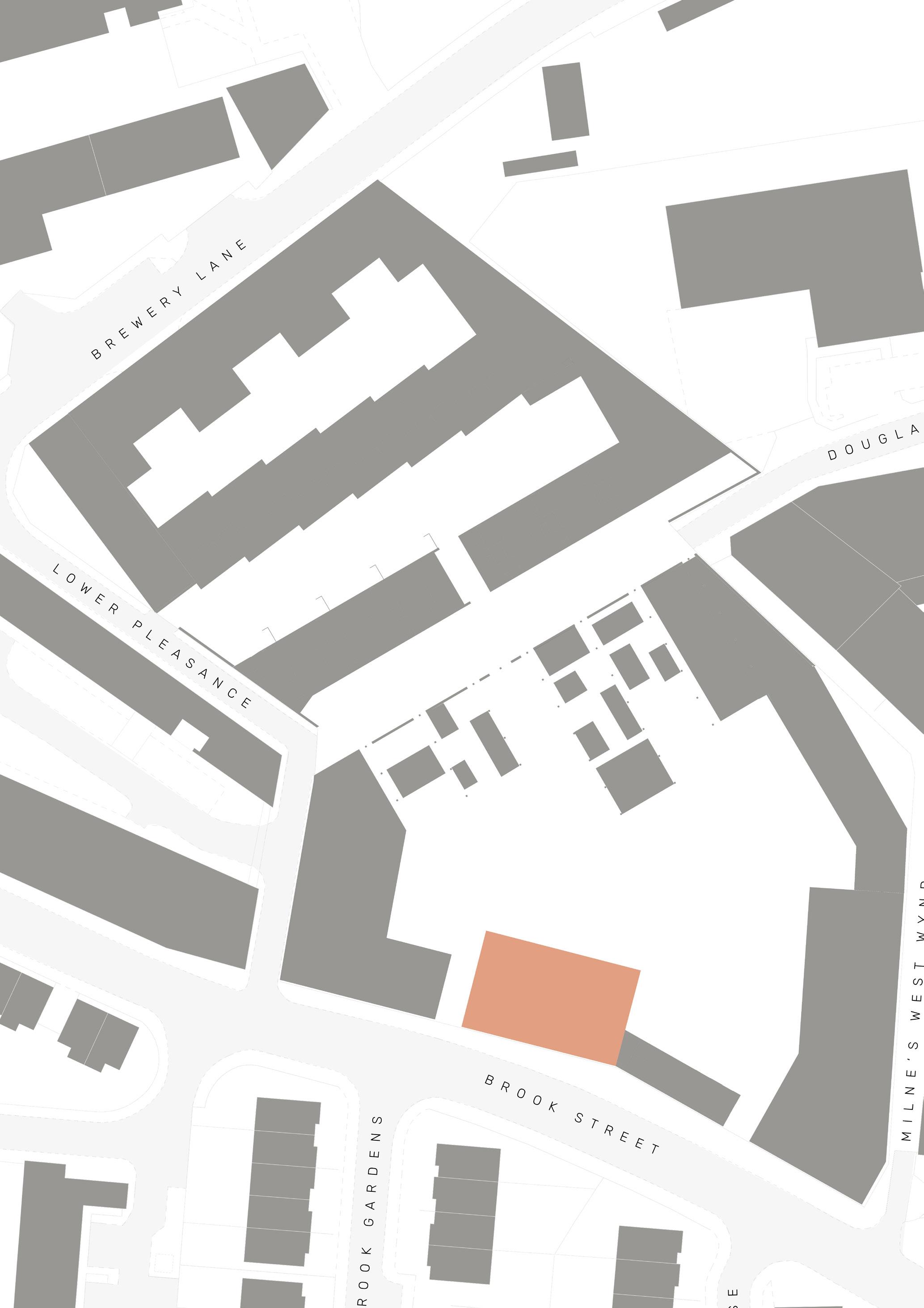
Brook Street


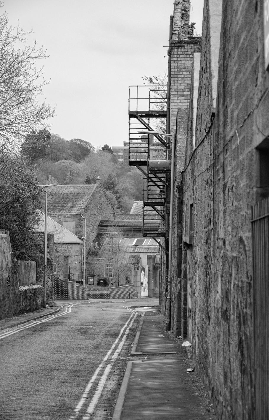
THE BUILDING WITH TWO FRONTS
‘‘the sun never knew how great it was until it struck the side of a building’ - Louis Kahn
Advertisement
With the buildings at Brook Street having more of a public presence compared to the other units on the site, it is important for them to be identifiable so they are easy to read, easy to find and be seen, easy to be a meeting place or node.
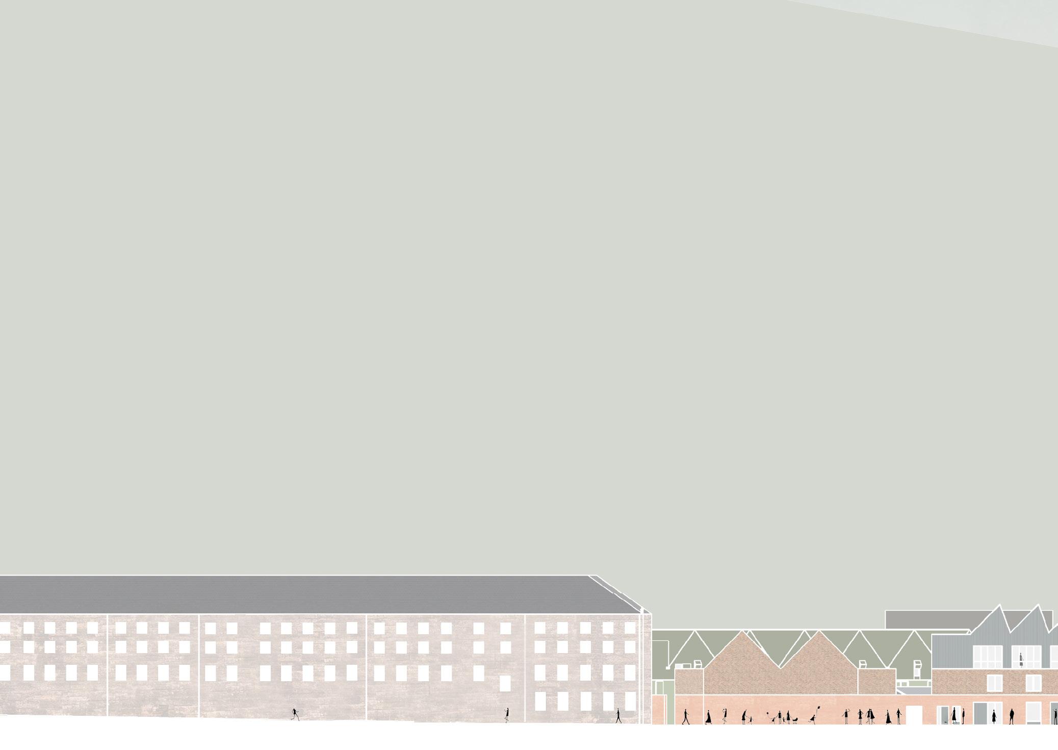
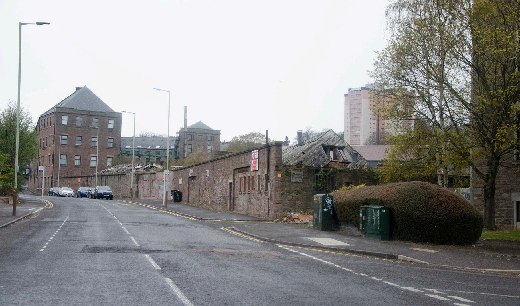
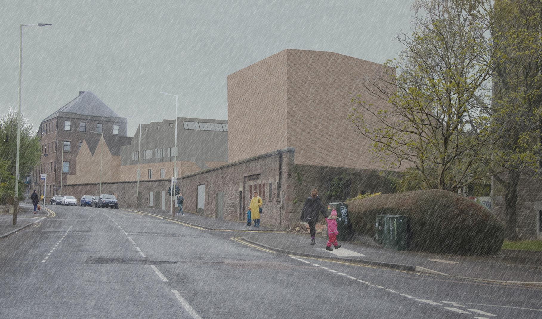
By using familiar materials the texture of the masses blend in whilst the forms themselves create a strong elevation with their bold roof pitches referencing the industrial context. The street composition of the building enables visitors to find it quickly as it is long and recognisable, when they find themselves in the courtyard, the scale changes and the elevation is reduced by half as it starts to cocoon around them. The images on the following page include a historic aerial photograph where the jute industry buildings were still standing strong and the aesthetic of the site was at its best before it was left to deteriorate. This is the vision that is trying to be brought back into the area.
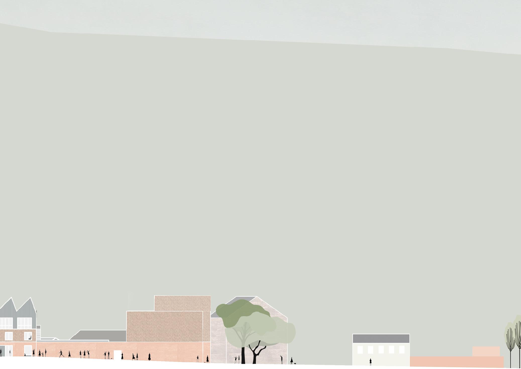
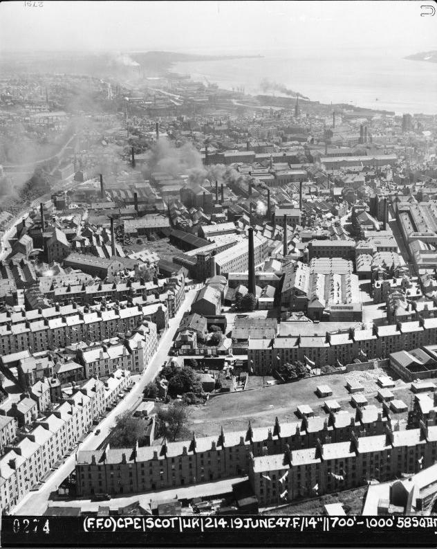
Figure 15 : Aerial photograph of Dundee from NW in 1947 showing mills and jute works. The view is looking down Milnbank Road and Pole Park Road
Testing this formal division on all façades questioning whether it was suitable.
The last row shows how if rammed earth is placed where the existing wall is on the front facade, it seamlessly allows the building to feel more part of the wall and vice versa.
Industrial materials (corrugated metal and brick) along with external escape stairs reflect the nature of the site in a modern way.
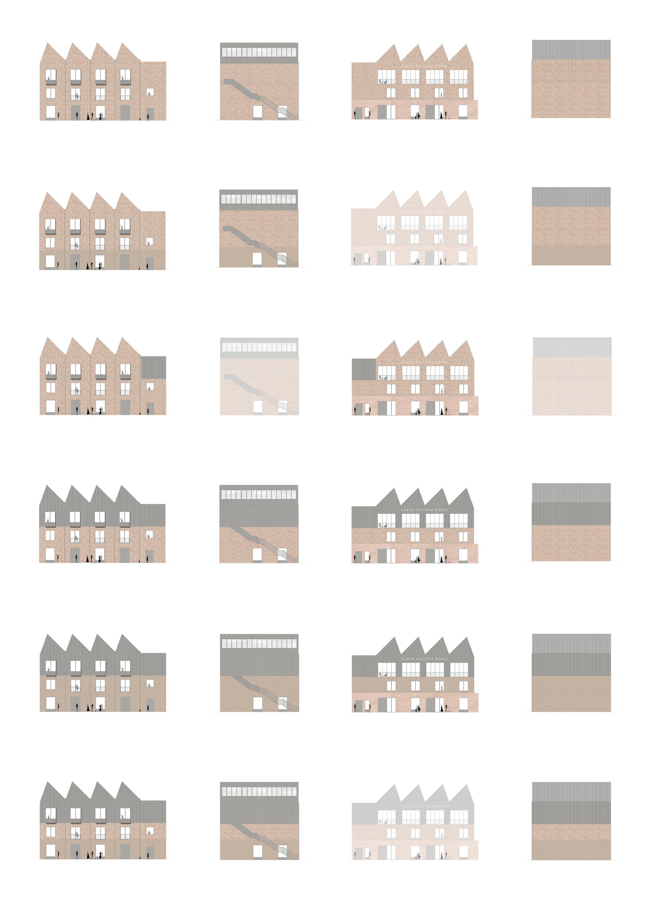
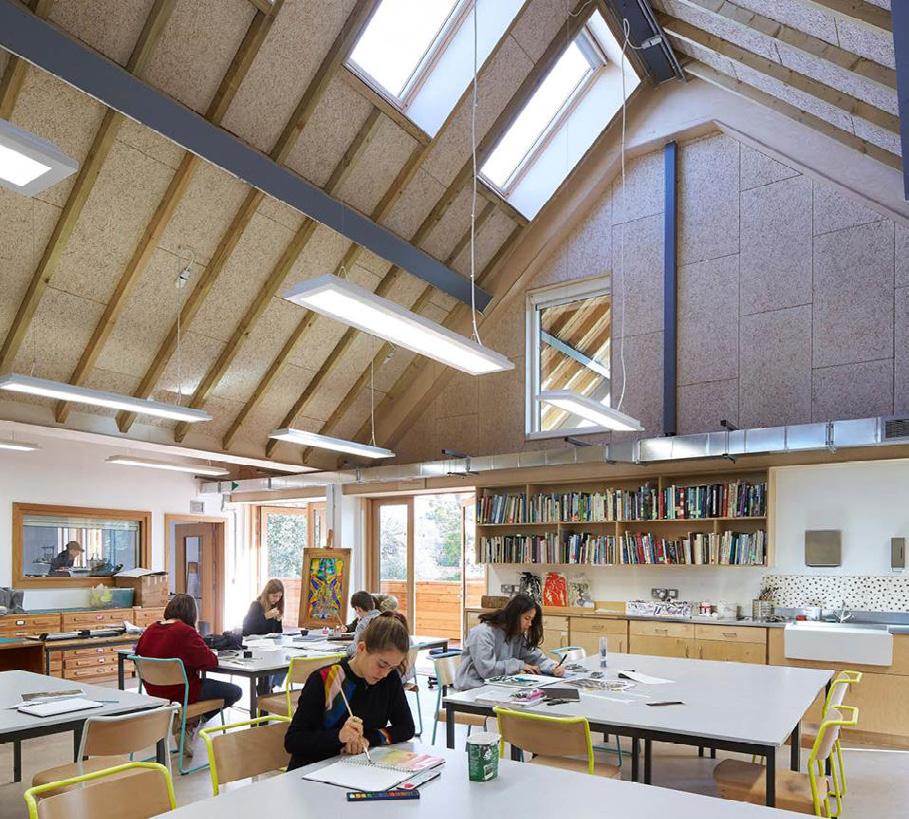
Figure 16 : Bedales School, Feilden Clegg Bradley Studios
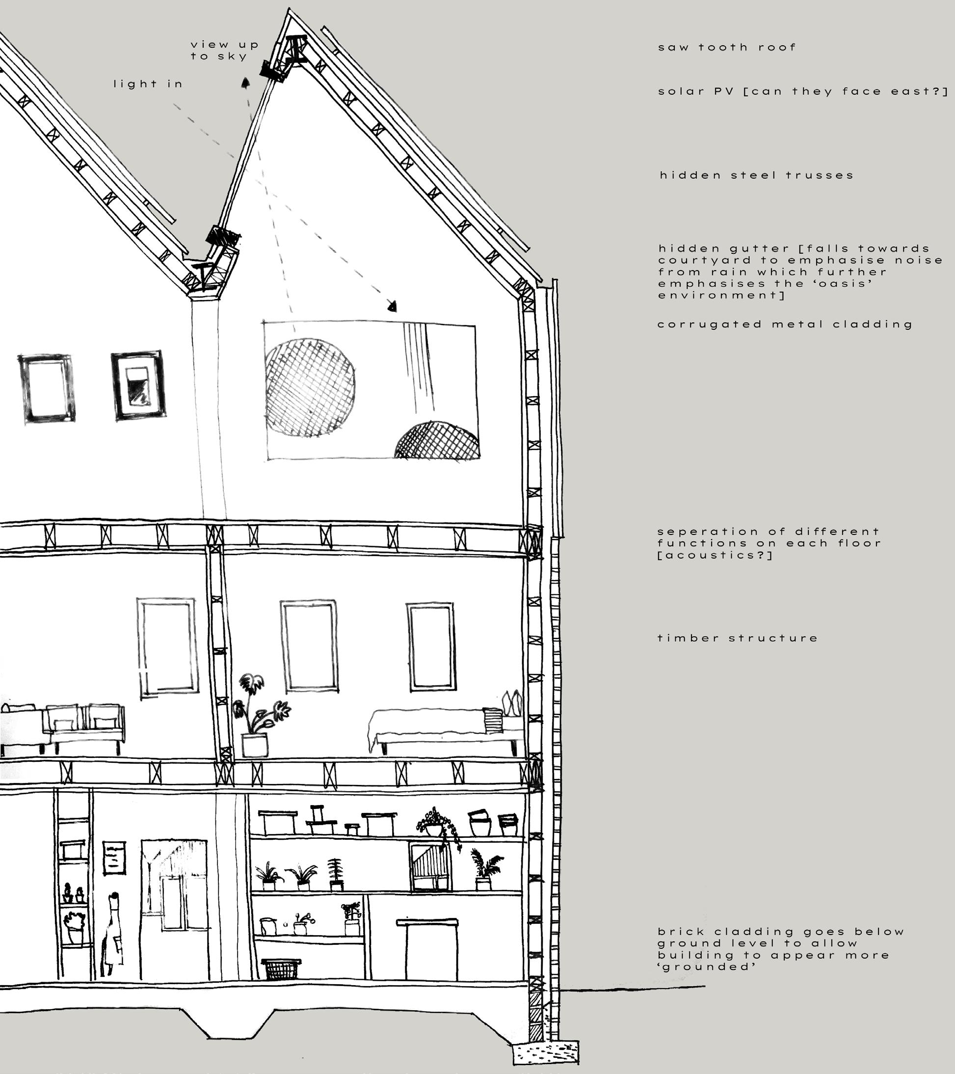
With Dundee being Scotland’s ‘sunniest city’ and gaining the nickname ‘Sundee’ it also makes sense to make best use of this. Through the use of top lit design (taking reference from Zenithal light in Journal 1) and PV Panels, the sun in Dundee is utilised where buildings are heated how nature intended. The factory roof structure with clean ‘warm’ roof spaces, not only allows natural light in, it is another reference to the industrial form, strengthening the legibility of the area.
There was an initial recognition of the different function on each level, where sound separation (acoustic boards/ insulation) is incredibly important.
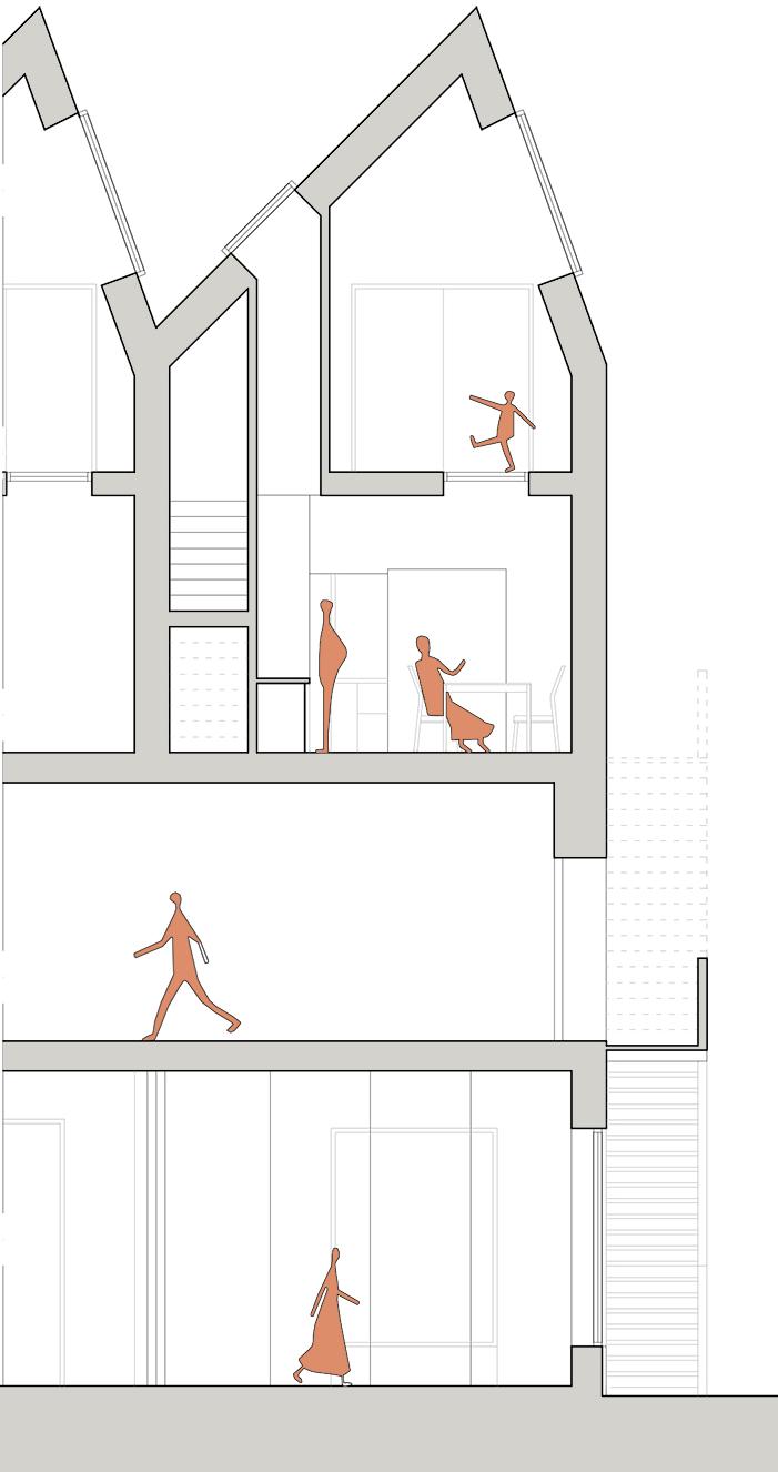
Initially the construction was to be quick and easy to put up but it was soon realised that the concept was not shown through the section. The simple timber construction was transformed into a solid to light principle where nature was then integrated deeper into the concept and construction of the design.
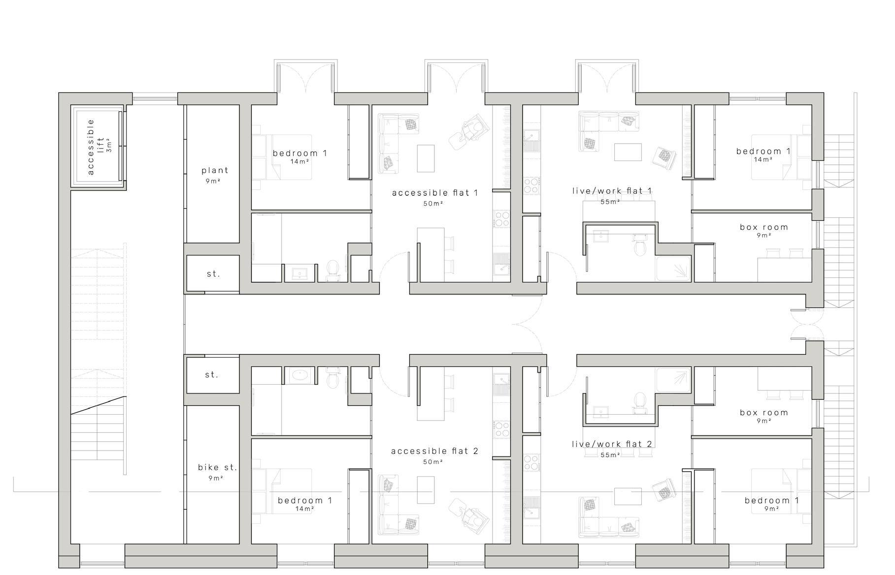
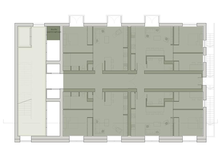
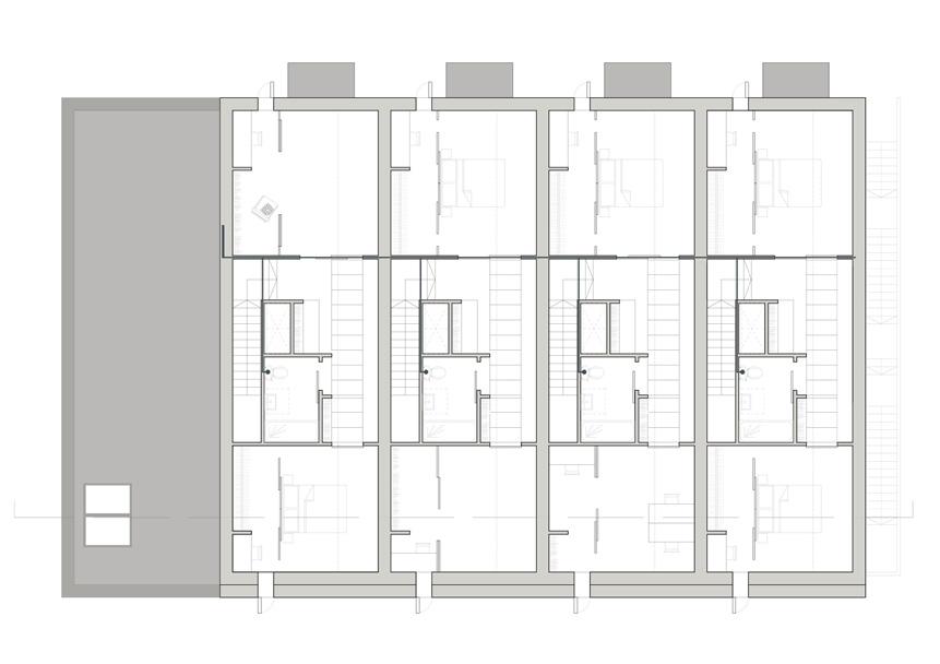
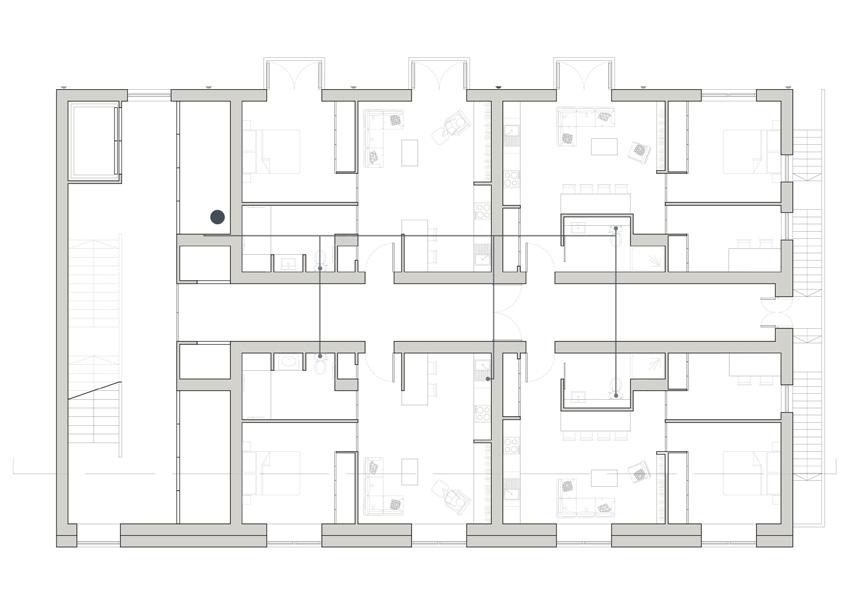
First Floor Plan (2x accessible flats + 2x live work flats)
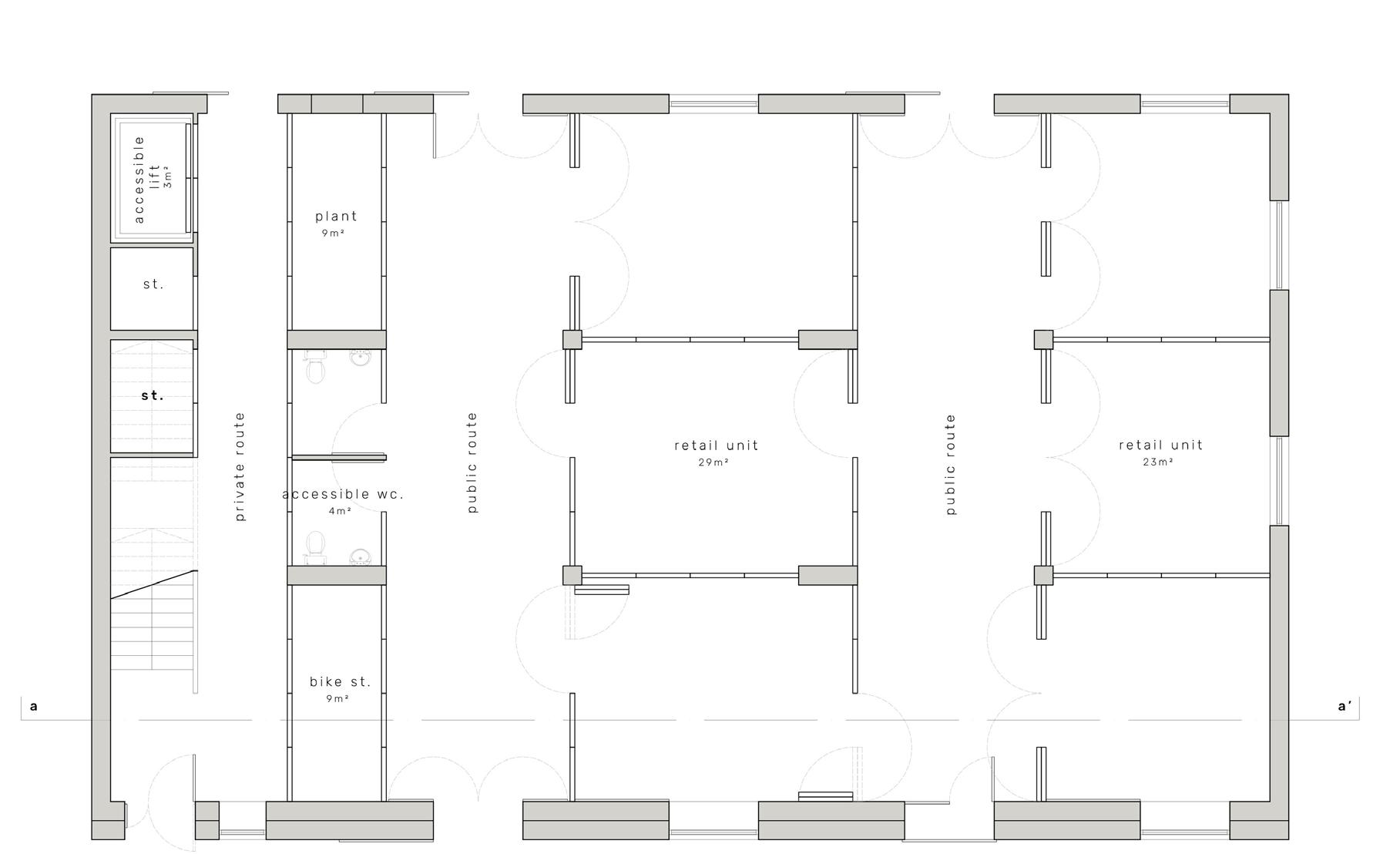
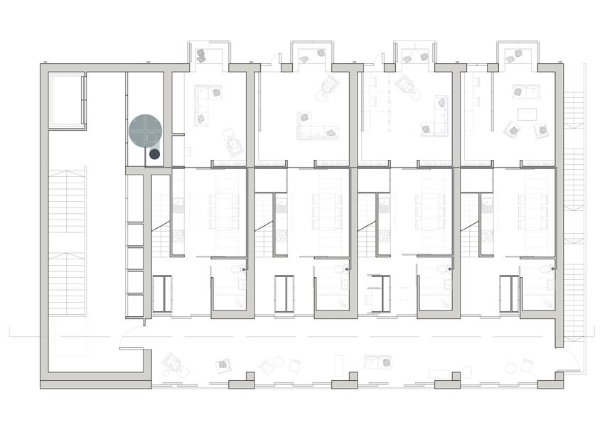
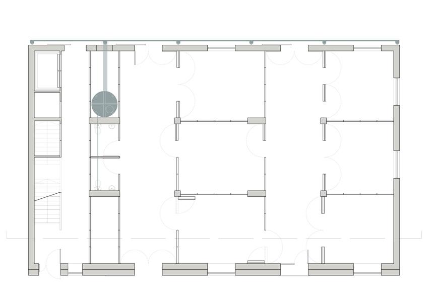
Ground Floor Plan (retail)
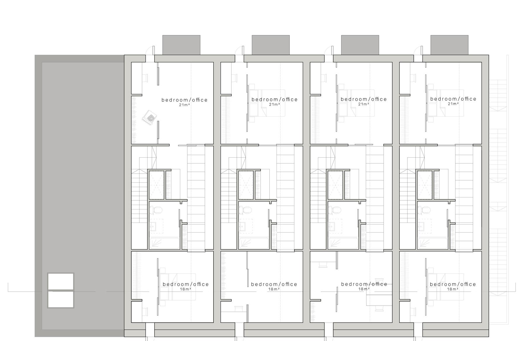
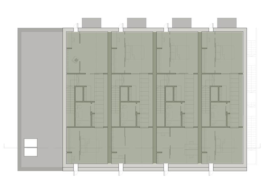
Third Floor Plan
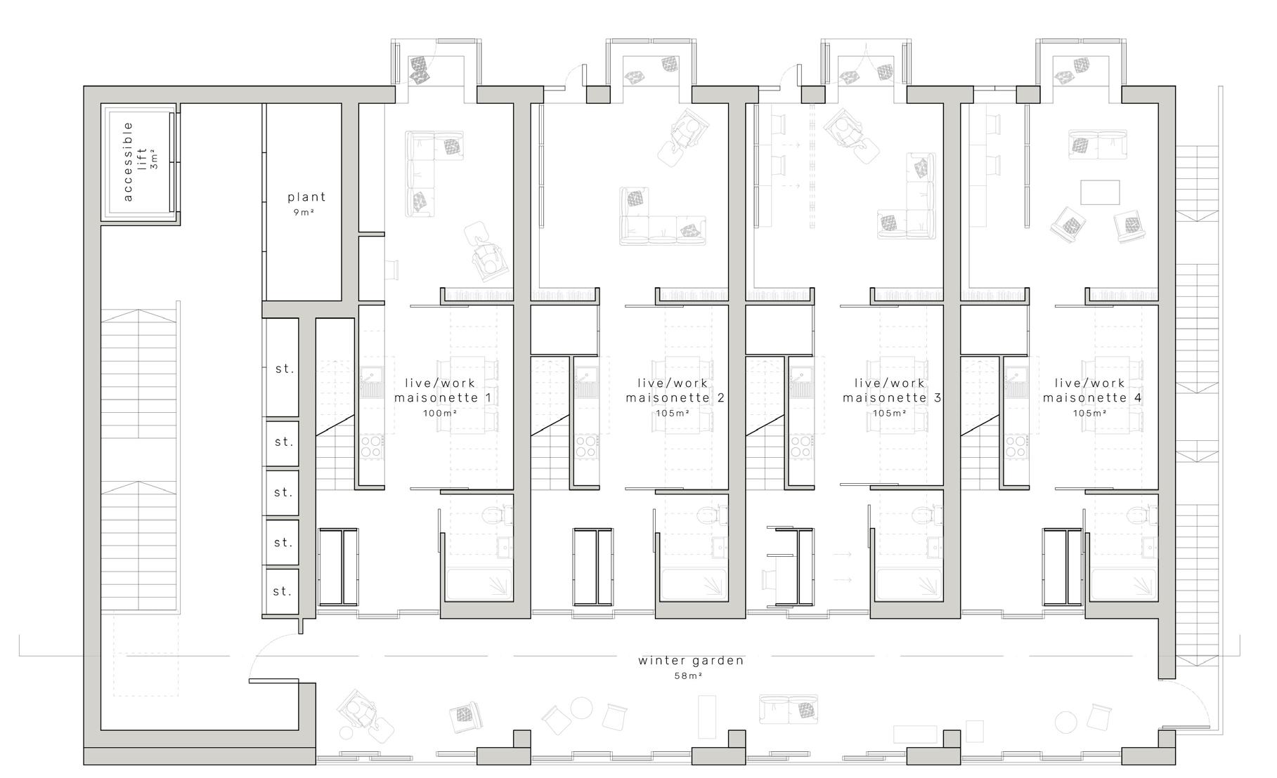
Second Floor Plan (4x live work maisonette flats)
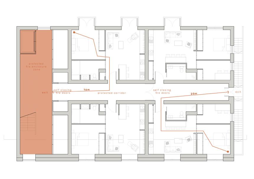
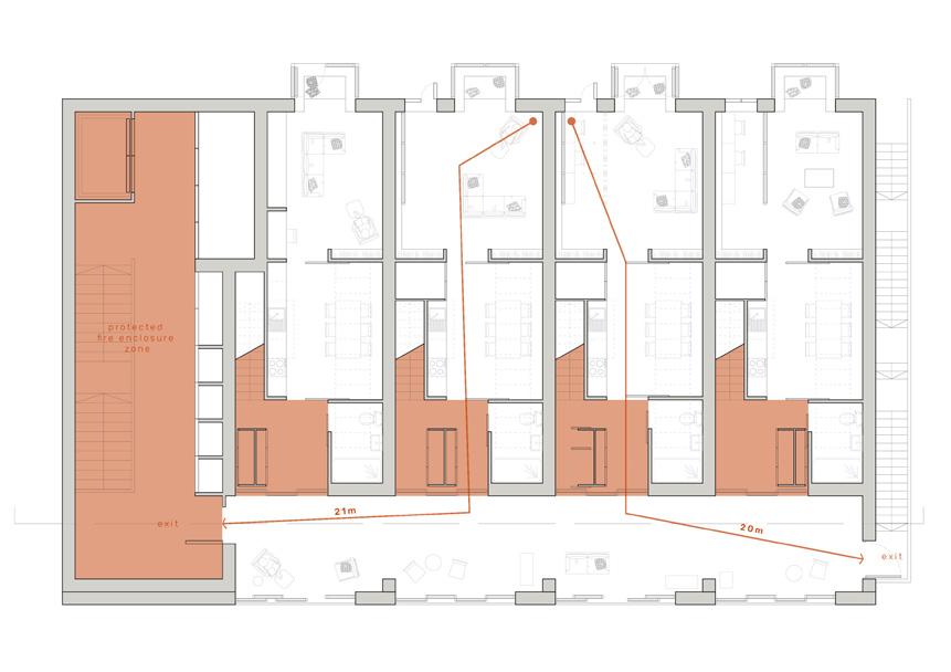
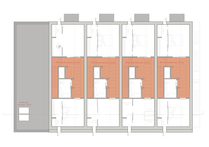
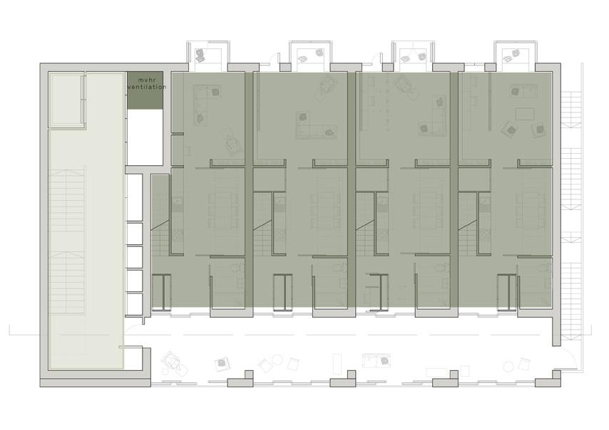
The following diagrams are designed to demonstrate fire, ventilation and rainwater strategies. With the ground floor being more public and having doors opening and closing all the time it seems more appropriate to have an HVAC system at the ground and in the stair well with the upper floors using a Mechanical Ventilation Heat Recovery (MVHR) system, as the environment is more consistent and ‘airtight’.
fire
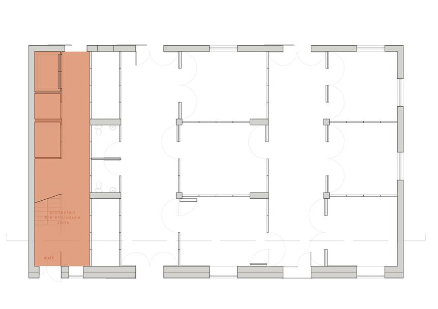
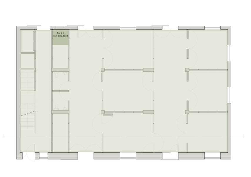
ventilation (hvac ground floor, mvhr upper floors)
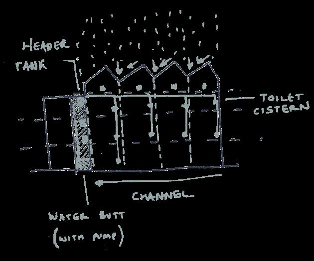
Referring to number ‘1’ on the rainwater structure diagram previously shown [page 23/24] the idea of reusing the rainwater within the building starts to form.
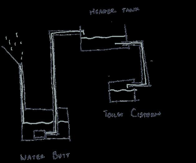
The basic diagrams below show the principles of how this process would work in terms of flushing a wc. 1. rainwater collected 2. taken down North elevation (similar to family units [refer to pages 113/114]) 3. runs along channel in the ground parallel with building 4. stored in water butt at ground floor 5. pumped up to a smaller header tank
6. gravity fed to individual flats
The average person uses 142l of water per day for drinking, cooking, showering, laundry, flushing toilets etc. By ensuring the rainwater is treated and cleaned, it can be used for all these functions.
With the 8 upper floor flats accommodating up to 22 people and the retail 6 (1 owner per unit) the total consistent amount of water used per day would be just under 4000l.
The ground floor has space to hold a tank of 5400l (1800 diameter x 3000mm height) which allows for number of visitors using facilities to fluctuate.
rainwater (reused for wc’s)
In terms of ASD, it is necessary for buildings to be clear to allow for the ease of navigation. Informative signage on buildings helps with the navigation on site for residents and also visitors, where meeting places can be created.
Signage also creates a strong ‘brand identity’ where the site which has the aim of creating an ASD community can be easily identified. With this identity built up, other micro-communities can be connected across the city and other cities, which creates a sense of comfort for users as they can visit other communities with a feeling on familiarity.
By creating recognisable buildings stamped with their own brand can make wayfinding a more positive experience which may otherwise be stressful, especially for those with ASD.
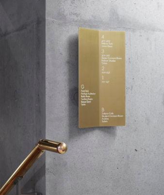
Figure 17 : exeter college, alison brooks architects

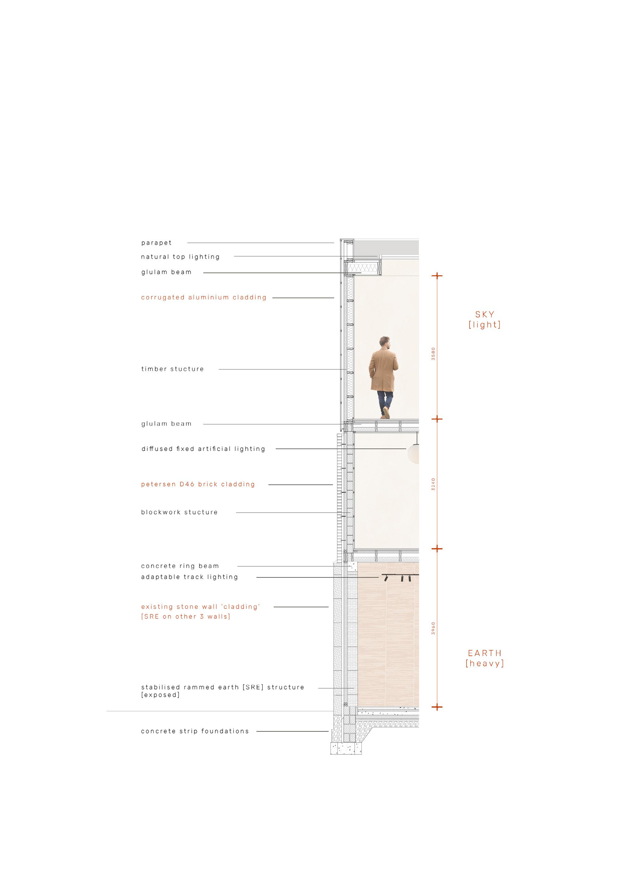
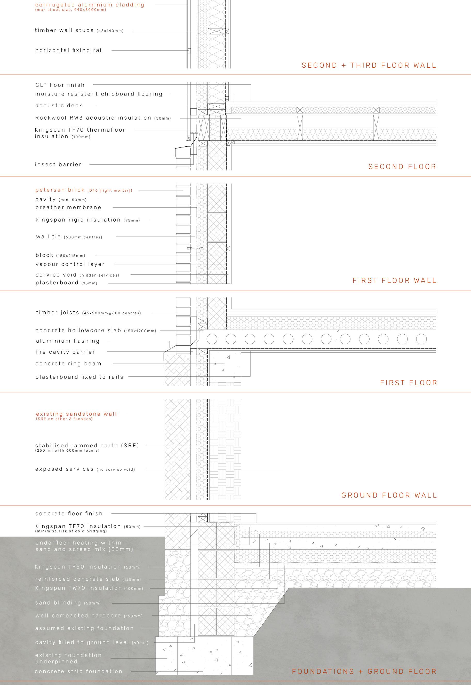
structural concept diagram 1:75 @ A4
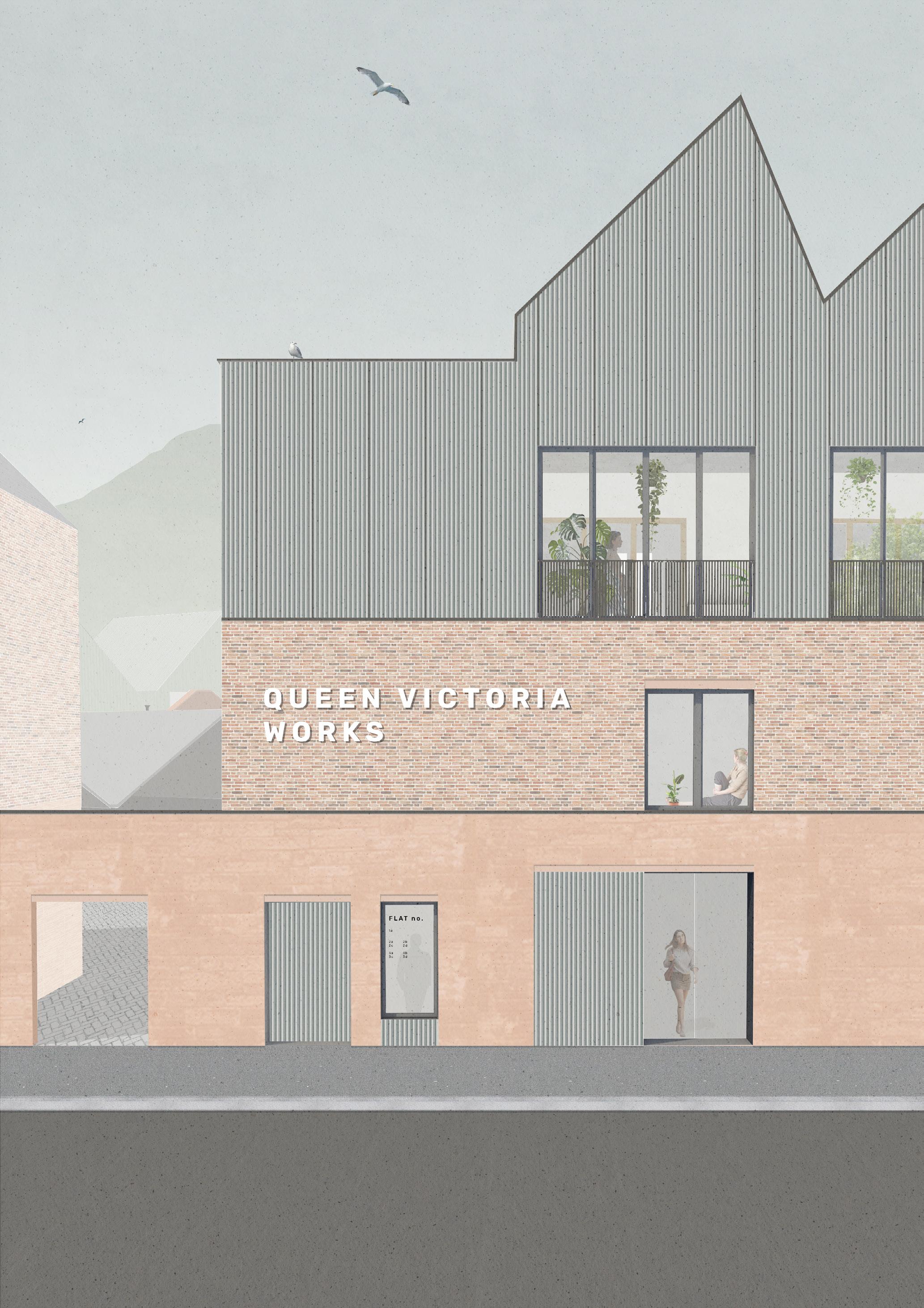
The building elevations are designed to be a honest expression of industrious materials, true to the area along with the building’s construction methods which is re-enforced by the conceptual links to the natural environment (heavy to light material palette as a reference to earth and sky). At ground floor the walls are constructed of rammed earth which utilises crushed and compacted rubble from the site in the mix. A timber frame structure sits on top of this, which is then clad with a brick skin at first floor and above this is corrugated steel cladding above. The construction methods at each level means that the facade steps back at each level, emphasising the different functions and creating a formal facade.
These steps are a result of having the cavity, insulation and structure in line, meaning the true properties of the external materials (deep rammed earth, to medium brick to thin aluminium) are demonstrated.
Along with the walls, the floor structures also change at each level, from solid concrete to a light weight timber the concept of earth to sky is echoed in all aspects of construction. Looking at the section on the previous page, it can be noted that ‘heavy to light’ principle was not followed in terms of the floor structure, so to strengthen the idea further, the first floor structure was changed. The hollowcore first floor also provides greater acoustic separation and fire protection between the residential flats above and retail units below. It also completes the ground floor zone, where there is a solid base and lighter upper structure. Underfloor heating is positioned on the ground floor, acting almost like the hot springs in Iceland and to keep the walls free for the adaptability of the floor. Track lighting on the ground floor again allows for adaptability, with fixed pendant lighting on the upper floors for a more residential scale.
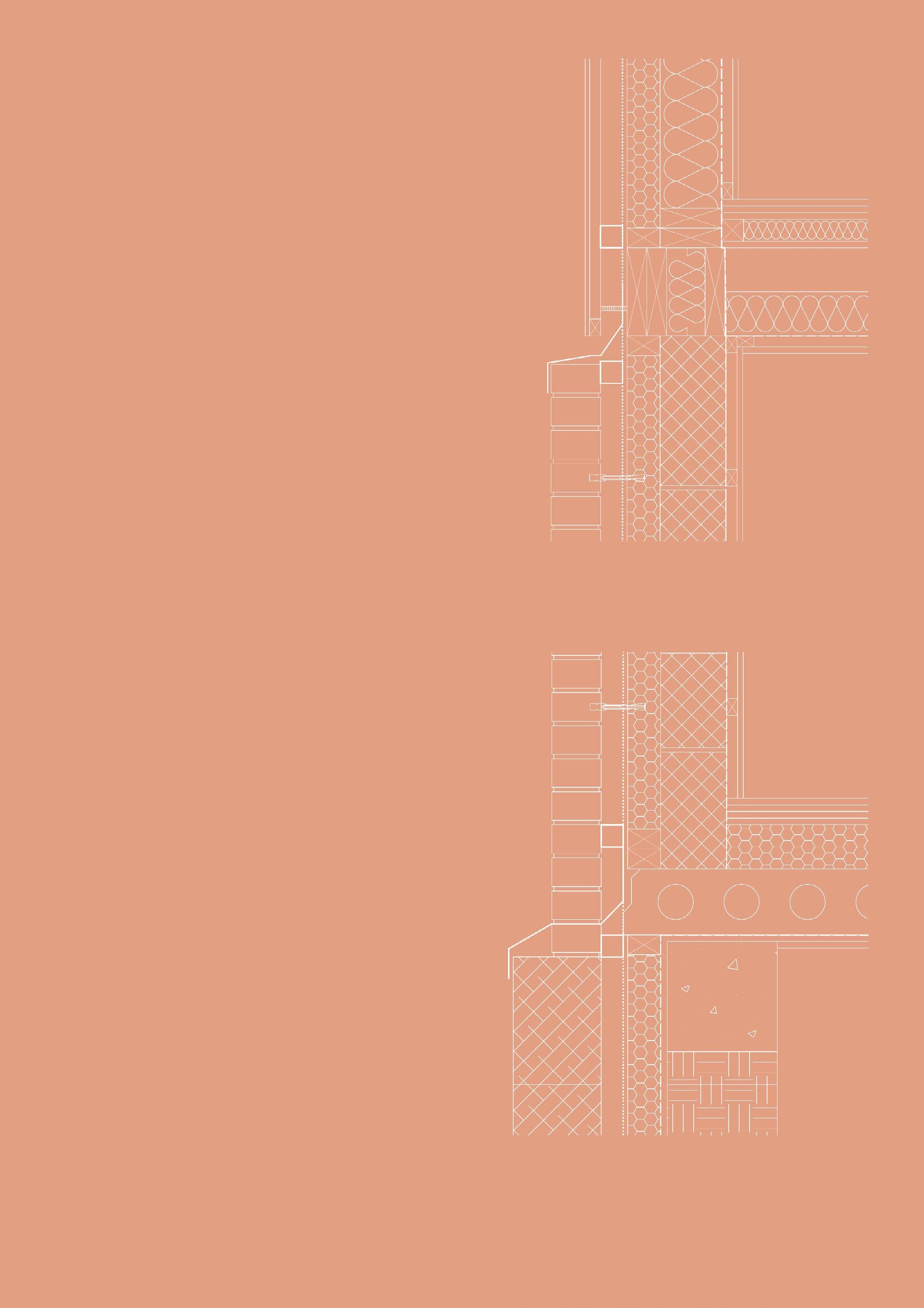
second floor wall junction detail 1:10 @ A4
first floor wall junction detail 1:10 @ A4
RAMMED EARTH
no stabilisers used
soil with a high clay content must be used
remains water soluble, hence will collapse if moisture rises above 13%
wide eaves and surface protectant required to protect from rain
cladding systems or regular coats of lime wash or render required on external surface
needs to have additional exterior or interior layer of insulation and cladding
STABILISED RAMMED EARTH (SRE)
insoluble, unaffected by immersion
unaffected by rain
thermal mass effect is lost if interior insulation is used
normally 500-700mm thick
larger foundations are needed to support thicker walls
slow drying means it can take up to 2 months to get near full strength
significant and unpredictable shrinkage occurs as wall sets due to high proportion of clay as binder
poor results with reinforcement (only small openings possible) requires normally 4% or 12% cement as stabiliser
soil, quarry waste, or recycled building rubble can be used
no exterior protection required
insulation can be incorporated
benefit of high thermal mass is maintained
normally 300mm thick
regular foundations suitable
relatively quick drying with 70% of full strength being achieved within 7 days
very small amounts of shrinkage as wall sets
can incorporate steel reinforcing, lintels, etc, so windows, doors, and large openings can be formed in wall
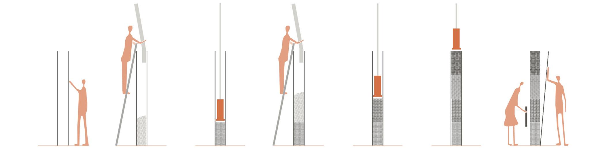
1 2 3 4 5 6 7
reinforced (pre oiled) plywood formwork constructed first layer of moist earth (mixture of soil, site rubble and cement) poured layer is compacted with pneumatic backfill tamper next layer of earth mixture added compacted
process is repeated until desired wall height is achieved formwork is removed
SRE is a material which is used in the UK more than people realise however it is less common in Scotland. The process can be time consuming but is relatively simple, and is a way to bring community together. Whilst specialists are needed, other, less experienced people could have the opportunity to help with the formwork and filling of levels. The sustainability of the site is important where the plywood used for the formwork (if pre-treated) could be used in kitchens and planters across other buildings on the site. The rammed earth also has multiple purposes from being load bearing, to insulating and fire resistant. The maintenance of the stabilised rammed earth is minimal due to the addition of cement, it acts more like concrete rather than regular rammed earth.
Aswell as the properties of SRE allowing the ground to ‘crawl’ up and ‘support’ the building, the patterning of the levels are very natural, looking almost like hills in the landscape. The formwork provides more definitive markings, where the pattern can be controlled and measured accurately to create a rhythmic grid.